1
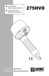
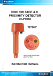
275HVD DETECTOR DE ALTA TENSIÓN SIN CONTACTO 11kV 22k V NON-CONTACT, HIGH VOLTAGE DETECTOR 33 kV V k 2 3 1 k V 5 7 2 6kV kV V 0 ST 4 2 TE OFF 2 ENGLISH User Manual E S PA Ñ O L Manual de Instrucciones Statement of Compliance Chauvin Arnoux®, Inc. d.b.a. AEMC® Instruments certifies that this instrument has been calibrated using standards and instruments traceable to international standards. We guarantee that at the time of shipping your instrument has met its published specifications. The recommended calibration interval for this instrument is 12 months and begins on the date of receipt by the customer. For recalibration, please use our calibration services. Refer to our repair and calibration section at www.aemc.com. Serial #: _________________________________ Catalog #: 2131.12 Model #: 275HVD Please fill in the appropriate date as indicated: Date Received: __________________________________ Date Calibration Due: ________________________ Chauvin Arnoux®, Inc. d.b.a AEMC® Instruments www.aemc.com WARNING! - READ BEFORE USE! Testing the 275HVD Before Operating: The 275HVD is a battery operated instrument. It must be carefully checked each time before use. (1) Test Before Use: Switch the sensitivity to “TEST”. The warning buzzer should emit A continuous audible tone and the warning light LEDs should stay lit up with the 275HVD in all positions. This indicates that the sensor is operational and the battery functional. If there is any intermittent buzzer and/or light, do not operate the 275HVD. Further operation is not to take place until authorized and qualified personnel have reviewed the operation and cleared the instrument after proper Test and Functional tests. (2) Detection Test: After a successful Test (1), perform the following steps to ensure that the 275HVD detects voltage on a known live conductor. • Select the 240VAC range and place the sensing head near a known live (low voltage) conductor (if not available, rub the sensor with a cloth or against a clothing item to generate a DC static charge which will trigger the sensor circuit detection). • The warning light and warning beeper should go ON as if a live conductor were being tested. NOTE: Positioning the sensing dome near a computer screen or a TV screen (not liquid crystal display type) should also trigger the tester while on the 240V selection. (3) Battery: • If any malfunction or instability of the light and/or buzzer occurs, then the user should also check the battery compartment and/or batteries. • When installing a new set of batteries or before use, tighten the battery compartment completely and properly (insure the O-ring is well seated), select the Test position and move the meter in different positions. In the Test mode the light and buzzer should remain ON continuously and be steady at all times. Otherwise, do not use the instrument. • Failure to properly close the battery compartment and/or the use of weak batteries may result in intermittent operation. Do not use the 275HVD if intermittent operation occurs (see Test Before Use). Non-Contact, High Voltage Detector 275HVD 1 Table of Contents Testing the 275HVD Before Operating...............................................1 1.INTRODUCTION................................................................................ 3 1.1 International Electrical Symbols.................................................4 1.2 Receiving Your Shipment...........................................................4 1.3 Ordering Information..................................................................4 2. PRODUCT FEATURES....................................................................... 5 2.1Description.................................................................................5 2.2 Typical Uses (always use a Hot Stick).......................................6 2.3 275HVD Features......................................................................7 3.SPECIFICATIONS............................................................................. 8 3.1Electrical....................................................................................8 3.2Mechanical.................................................................................8 3.3Environmental............................................................................8 3.4 Detection Levels........................................................................9 4.OPERATION................................................................................... 11 4.1 Preparation for Use.................................................................. 11 4.2 Limitations on the Model 275HVD........................................... 11 4.3 4.4 4.5 4.6 4.7 Testing the 275HVD Before Operating................................ 12 High Voltage Testing................................................................12 Low Voltage Testing.................................................................13 Faults (Open) in Cables...........................................................14 Changing the Batteries............................................................14 Repair and Calibration............................................................................15 Technical and Sales Assistance.............................................................15 Limited Warranty....................................................................................16 Warranty Repairs....................................................................................16 2 Non-Contact, High Voltage Detector 275HVD CHAPTER 1 INTRODUCTION Warning The Model 275HVD Non-Contact High Voltage Detector has been designed with safety in mind. However, no design can completely protect against incorrect use. The 275HVD should be used by trained and qualified personnel only. The 275HVD can only be used with an insulated rod or “Hot Stick” rated at the appropriate working voltage. The 275HVD Non-Contact High Voltage Detector is never to be put into direct contact with a live conductor. If caution or poor safety practices are not adhered to, electrical circuits can be dangerous and lethal. This instrument should only be used by authorized and properly trained personnel who fully understand the High Voltage testing procedures. Personnel working with high voltages should be trained regularly. • Read the user manual carefully and completely before using the tester. Fully understand the instructions before using this product. • Follow the instructions for every test. • Take all the necessary safety precautions. Do not exceed the limits of this instrument. • The 275HVD Non-Contact High Voltage Detector must never be in physical contact with any conductor. This is a proximity detector, not a detector which works by contact. • Tests must only be carried out with the 275HVD attached to an approved insulated fiberglass rod or Hot Stick. • Always use an authorized fiberglass (or equivalent) rod or Hot Stick appropriately rated for the voltage with which you are working. • Always check that the 275HVD Non-Contact High Voltage Detector is working before and after the test. • Verify the Range Switch setting before measuring. Make sure it is on the correct setting for your application. • Do not touch any exposed wiring, connections, or other “live” parts of an electrical circuit. Non-Contact, High Voltage Detector 275HVD 3 1.1 International Electrical Symbols This symbol on the instrument indicates a WARNING and that the operator must refer to the user manual for instructions before operating the instrument. In this manual, the symbol preceding instructions indicates that if the instructions are not followed, bodily injury, installation/sample and product damage may result. Risk of electric shock. The voltage at the parts marked with this symbol may be dangerous. 1.2 Receiving Your Shipment Upon receiving your shipment, make sure that the contents are consistent with the packing list. Notify your distributor of any missing items. If the equipment appears to be damaged, file a claim immediately with the carrier and notify your distributor at once, giving a detailed description of any damage. Save the damaged packing container to substantiate your claim. Do not use an instrument that appears to be damaged. 1.3 Ordering Information Non-Contact High Voltage Detector Model 275HVD........ Cat. #2131.12 Includes three 1.5V C-cell batteries, shotgun adapter, carrying case, and user manual. 4 Non-Contact, High Voltage Detector 275HVD CHAPTER 2 PRODUCT FEATURES IMPORTANT WARNING Never assume conductors that have been tested as de-energized will stay de-energized. Always install proper grounding devices before working. Failure to do so may result in serious injury or death. 2.1Description The Non-Contact High Voltage Detector Model 275HVD is a high voltage detector by proximity. It is not designed to enter into contact with conductors. The 275HVD should never touch conductors and must be used with an insulated fiberglass rod or Hot Stick appropriately rated for the voltage being tested. The Non-Contact High Voltage Detector Model 275HVD is not a “measuring instrument” per say, rather it is a product designed to warn the user of the presence of voltage in a particular work site. The 275HVD uses an internal sensor designed to detect the radiated electrical field (V/m) present in energized conductors. The radiated electrical field increases with the line voltage but decreases with distance and/or shielding. The 275HVD has eight voltage range settings. These correspond to internal field sensitivity settings: the lower the voltage setting; the higher the sensitivity to detect the electrical field; and, the greater the detection distance. It also has an “auto-test” setting to check functionality (see § 4.3). Non-Contact, High Voltage Detector 275HVD 5 The 275HVD is battery powered and contains three standard 1.5V “C” cells in the shaft below the sensing head. When an electrical field is detected, a sound annunciator (high-pitch, high -powered buzzer) and visual indicators (bright LEDs) are triggered ON, warning the user. The body is made out of industrial grade UL rated polyamide (Type 66 Nylon). The shotgun adapter at the shaft end is designed to fit into most Hot Stick adaptors. 2.2 • • • • • • • • Typical Uses (always use a Hot Stick) Identify and check live cables Check and detect live high voltage cables Find fault in flexible cables Check grounding equipment Service neon lighting Trace live wires Check high frequency radiation Detect residual or induced voltages IMPORTANT WARNING The 275HVD detects radiated electrical fields. To accomplish this, an energized cable or sample must radiate an electrical field. Shielded cables or shielded samples do not radiate, or radiate very small electrical fields. Also, cables with concentric neutrals will have a smaller/lower radiated field than plain insulated cables. The 275HVD may not detect, as expected, an electrical field on shielded cables (buried cables are often shielded) or shielded samples and the 275HVD has lower sensitivity on cables with concentric neutrals. It is not recommended to use the 275HVD on shielded cables or shielded samples. Use extreme care on cables with concentric neutrals (use a low setting). 6 Non-Contact, High Voltage Detector 275HVD 2.3 275HVD Features 1. Warning Light - Bright, low current Red LEDs triggered on voltage detection 2. Warning Buzzer - High noise level buzzer triggered on voltage detection 3. Rotary Selector with the following settings: • OFF - Turn the pick-up sensor off • TEST - Verifies that the circuitry is working • 240V - 2kV - 6kV - 11kV - 22kV - 33kV - 132kV - 275kV 4. Battery Holder 5. Shotgun adapter end fitting for Hot Stick connection Non-Contact, High Voltage Detector 275HVD 7 CHAPTER 3 SPECIFICATIONS 3.1Electrical Ranges: 240V, 2kV, 6kV, 11kV, 22kV, 33kV, 132kV, 275kV Detection Frequency: 40 to 70Hz Power Supply: Three 1.5V “C” cell batteries Power Consumption: 40mA Signal Lamp: 47 lux @ 20cm Sound Volume: 75 db @ 1m from detector 3.2Mechanical Case Height: 9" (229mm) Case Width: 3.78" (96mm) Weight: 1.30 lbs (0.59kg) batteries included Shock Test: IEC 68-2-29 Vibration Test: EN 61010, clause 8.3 Drop Test: EN 61010, clause 8.4 Impact Test: EN 61010, clause 8.2 3.3Environmental Operating Temperature: 5° to 130°F (-15° to 55°C) Storage Temperature: -4° to 150°F (-20° to 65°C) Humidity: 0 to 93% RH @ 104°F (40°C) Cold Temperature: IEC 68-2-1 Dry Heat: IEC 68-2-2 Damp Heat: IEC 68-2-3 8 Non-Contact, High Voltage Detector 275HVD 3.4 Detection Levels The 275HVD is used by moving it closer to the live conductor until the buzzer and light warnings are triggered. It is designed to detect at a lower voltage than the range setting. The following data is considered as typical response for the 275HVD. Variations may occur from unit to unit. As a general rule, in a “clean” environment, the 275HVD will trigger @ 45 to 65% of the voltage range at 4"/10cm, and detected the selected voltage setting at 8 to 12" (20 to 30cm). The following data provides indicative distances at which the 275HVD will detect a given voltage. Note that these tests were conducted in ideal test conditions (unshielded single conductor, lab environment, sensor head perpendicular to conductor) and are not fully representative of the work site, which may have other voltages present (and which may influence the overall results). The distances should only be taken as indicative and not as electrical specifications. Care should be taken when in presence of other conductors which may also be detected by the 275HVD (see § 4.2). Measurements are based upon a 90° angle (sensor head perpendicular to conductor). Range Setting 240V 2kV 6kV 11kV 22kV 33kV 132kV 275kV Distance 4" – 10cm 4" – 10cm 4" – 10cm 4" – 10cm 4" – 10cm 4" – 10cm 4" – 10cm 4" – 10cm Voltage Detection 75V – 90V 1.3kV 3.6kV 7.5kV 11kV 19.5kV Not Rated Not Rated Range Setting 240V 2kV 6kV 11kV 22kV 33kV 132kV 275kV Voltage 240V 2kV 6kV 11kV 22kV 33kV 132kV 275kV Distance 10.5" - 27cm 10.5" - 27cm 11.5" - 29cm 10.5" - 27cm 12.2" - 31cm 11.0" - 28cm 10.0" - 25cm 10.0" - 25cm Non-Contact, High Voltage Detector 275HVD 9 The following information provides typical detection distances when using a lower setting than the line voltage. Note that the distances may vary with each unit and will be affected based on the actual environment. The values displayed were conducted in an ideal lab environment and cannot represent each field environment. 10 SETTING 240VAC 240VAC 240VAC 240VAC 240VAC 240VAC VOLTAGE 500VAC 1kVAC 2kVAC 6kVAC 11kVAC 22kVAC DISTANCE 12" - 32cm 18" - 48cm 29" - 75cm 48" - 124cm 57" - 146cm 89" - 226cm SETTING 2kVAC 2kVAC 2kVAC 2kVAC VOLTAGE 6kVAC 11kVAC 22kVAC 33kVAC DISTANCE 16" - 40cm 20" - 52cm 24" - 60cm 36" - 92cm SETTING 6kVAC 6kVAC 6kVAC VOLTAGE 11kVAC 22kVAC 33kVAC DISTANCE 24" - 61cm 29" - 75cm 41" - 105cm SETTING 11kVAC 11kVAC VOLTAGE 22kVAC 33kVAC DISTANCE 13" - 35cm 16" - 42cm SETTING 22kVAC VOLTAGE 33kVAC DISTANCE 14" - 36cm Non-Contact, High Voltage Detector 275HVD CHAPTER 4 OPERATION 4.1 Preparation for Use The Non-Contact High Voltage Detector should be inspected for any visible signs of damage before using, battery condition and the checks described below should be performed to ensure that it is operating correctly. When you first receive it, if there is any sign of damage or if the instrument does not operate correctly, return it to the distributor from which it was purchased. 4.2 Limitations on the Model 275HVD See Warning on Page 5 & 6 • Testing voltages on cable composed of multiple phases may be a problem. In particular, multiple phase cables twisted together may have their electrical fields canceling each other out (vector sum), and a much lower detectable field signal may result. This may lead to non-detection if the range setting is too high. Try a lower range setting if this situation occurs. Keep in mind that the actual line voltage may be much higher! • Problems can arise when the 3-phase circuit of a 275/133/11kV transformers are tested. The electric field of the HV and MV bus bars can trigger the detector when it is about one meter (approx 3 ft) above the ground. Users must be aware that this is common with most of the electric field voltage detectors. The 275HVD can pick up adjacent circuit electrical fields to the one being tested and may indicate the wrong information to the user. • Electrical Field sensitivity is reduced when the 275HVD is used close to grounding points. • The Model 275HVD will work on cables with a concentric neutral. • The Model 275HVD will not work on shielded cables. Non-Contact, High Voltage Detector 275HVD 11 4.3 Testing the 275HVD Before Operating ( also READ Important warning on page 1) Switch the sensitivity to “TEST”. The warning buzzer should emit continuous audible tone and the warning light LEDs should light up. This indicates that the sensor is operational and the battery functional. Perform the following steps to ensure that the 275HVD detects voltage on a known live conductor. • Select the 240VAC range and place the sensing head near a known live (low voltage) conductor (if not available, rub the sensor with a cloth or against a clothing item to generate a DC static charge which will trigger the sensor circuit detection). • The warning light and warning beeper should go ON as if a live conductor were being tested. NOTE: Positioning the sensing dome near a computer screen or a TV screen (not liquid crystal display type) should also trigger the tester while on the 240V selection. 4.4 High Voltage Testing See Warning on Page 5 & 6 The 275HVD Non-Contact High Voltage Detector works by proximity. It is not designed to be in physical contact with live conductors. Its sensor detects the radiated field which surrounds live conductors. Do not touch live conductors with the 275HVD Non-Contact High Voltage Detector. Radiated field strength increases with voltage and decreases quickly with distance and/or ground shielding. The radiated field from a cable where conductors supplying three-phase power are close together, tends to cancel out (See § 4.2). The rotary switch (attenuator) is used to identify and differentiate various HV live cables. The tester must only be used with an appropriate insu lated rod or Hot Stick when measuring High Voltage. 12 Non-Contact, High Voltage Detector 275HVD After checking the 275HVD and ensuring its good operation, select the test range. It is recommended to start with a lower setting than the actual working voltage, and then to try again with higher settings. The user may also consider using lower settings to check for lower voltages on a conductor. With the 275HVD at the end of a hot stick, move towards the live conductor until its warnings are triggered. 11kV 6kV 2kV 240V 22kV TEST 33kV OFF 132kV 275k V tick Hot S 4.5 Low Voltage Testing See Warning on Page 5 & 6 The 275HVD Non-Contact High Voltage Detector works by proximity. The 275HVD is not designed to be in physical contact with live conductors. Its sensor detects the radiated field that surrounds live conductors. Do not touch live conductors with the 275HVD Non-Contact High Voltage Detector. Radiated field strength increases with voltage and decreases quickly with distance and/or ground shielding. The radiated field from a cable where conductors supplying three-phase power are close together, tends to cancel out (See § 4.2). Detecting distance of a 250VAC single live wire is about 4" (10cm). When grouped with neutral and ground wires, as in a flexible cable, the distance is reduced to 2" (5cm) or less. Non-Contact, High Voltage Detector 275HVD 13 4.6 Faults (Open) in Cables See Warning on Page 5 & 6 Ho tS tick Faults in certain flexible cables can be detected with the 275HVD. If the cable is still energized, set the 275HVD sensitivity so that it triggers, then move the 275HVD along the cable until a change in condition is obtained. An audible tone and LED should be on when the sensor is on the supply side of the open and will turn off when on the other side. 27 5k 132 V kV 33kV OFF 22kV V 2k 6kV V 11kV TEST 240 4.7 Changing the Batteries Batteries should be checked with a multimeter and replaced periodically. The 275HVD Non-Contact High Voltage Detector uses 3 x 1.5V “C” cell batteries. Open the battery compartment (turn the shaft counter-clockwise) to remove the batteries. Ensure that polarity is respected when installing new batteries. 14 Non-Contact, High Voltage Detector 275HVD Repair and Calibration To ensure that your instrument meets factory specifications, we recommend that it be scheduled back to our factory Service Center at one-year intervals for recalibration, or as required by other standards or internal procedures. For instrument repair and calibration: You must contact our Service Center for a Customer Service Authorization Number (CSA#). This will ensure that when your instrument arrives, it will be tracked and processed promptly. Please write the CSA# on the outside of the shipping container. Ship To: Chauvin Arnoux®, Inc. d.b.a. AEMC® Instruments 15 Faraday Drive Dover, NH 03820 USA Phone:(800) 945-2362 (Ext. 360) (603) 749-6434 (Ext. 360) Fax: (603) 742-2346 or (603) 749-6309 E-mail:[email protected] (Or contact your authorized distributor) Costs for repair and standard calibration are available. NOTE: You must obtain a CSA# before returning any instrument. Technical and Sales Assistance If you are experiencing any technical problems, or require any assistance with the proper operation or application of your instrument, please call, mail, fax or e-mail our technical support team: Chauvin Arnoux®, Inc. d.b.a. AEMC® Instruments 200 Foxborough Boulevard Foxborough, MA 02035 USA Phone:(800) 343-1391 (508) 698-2115 Fax: (508) 698-2118 E-mail:[email protected] www.aemc.com NOTE: Do not ship Instruments to our Foxborough, MA address. Non-Contact, High Voltage Detector 275HVD 15 Limited Warranty The Model 275HVD Non-Contact High Voltage Detector is warranted to the owner for a period of three (3) years from the date of original purchase against defects in manufacture. This limited warranty is given by AEMC® Instruments, not by the distributor from whom it was purchased. This warranty is void if the unit has been tampered with, abused or if the defect is related to service not performed by AEMC® Instruments. For full and detailed warranty coverage, please read the Warranty Coverage Information, which is attached to the Warranty Registration Card (if enclosed) or is available at www.aemc.com. Please keep the Warranty Coverage Information with your records. What AEMC® Instruments will do: If a malfunction occurs within the three-year period, you may return the instrument to us for repair, provided we have your warranty registration information on file or a proof of purchase. AEMC® Instruments will, at its option, repair or replace the faulty material. REGISTER ONLINE AT: www.aemc.com Warranty Repairs What you must do to return an Instrument for Warranty Repair: First, request a Customer Service Authorization Number (CSA#) by phone or by fax from our Service Department (see address below), then return the instrument along with the signed CSA Form. Please write the CSA# on the outside of the shipping container. Return the instrument, postage or shipment pre-paid to: Ship To: Chauvin Arnoux®, Inc. d.b.a. AEMC® Instruments 15 Faraday Drive • Dover, NH 03820 USA Phone:(800) 945-2362 (Ext. 360) (603) 749-6434 (Ext. 360) Fax: (603) 742-2346 or (603) 749-6309 E-mail:[email protected] Caution: To protect yourself against in-transit loss, we recommend you insure your returned material. NOTE: You must obtain a CSA# before returning any instrument. 16 Non-Contact, High Voltage Detector 275HVD Notes: Non-Contact, High Voltage Detector 275HVD 17 ATENCIÓN: LEA ESTAS INSTRUCCIONES ANTES DE USAR EL INSTRUMENTO Como verificar el detector de alto voltaje modelo 275HVD antes de su uso: El modelo 275HVD es un instrumento que utiliza baterías para su funcionamiento. Por favor siga los siguientes pasos antes de usar este instrumento. (1) Prueba antes del uso: Seleccione “TEST”. El zumbador de precaución emitirá un sonido continuo y audible y la luz de advertencia de la pantalla LED permanecerá encendida en todas las selecciones del modelo 275HVD. Esto indica que tanto el sensor como la batería se encuentran en perfecto estado de operabilidad. No utilice el modelo 275HVD en caso de escucharse el zumbador y/o ver una luz intermitente. No utilice el instrumento hasta que personal autorizado y calificado lo haya evaluado y haya autorizado su uso después de efectuar los chequeos de correcto funcionamiento. (2) Prueba de detección: Una vez completada satisfactoriamente la Prueba (1), siga los siguientes pasos para asegurar que el modelo 275HVD detecta voltaje en un conductor conocido que tenga voltaje. • Seleccione el rango de 240 VAC y coloque el terminal de medición cerca de un conductor conocido que tenga voltaje (si no hubiese uno disponible, frote el sensor con un paño o en contra de prendas de vestir para generar una carga estática de CC que disparará la detección del circuito del sensor). • La luz y el zumbador de advertencia deben continuar ON como si se estuviese probando un conductor con tensión. NOTA: Seleccionando 240V, el instrumento se debería activar al colocar el terminal del sensor cerca de una pantalla de computadora o una pantalla de TV (no el tipo de pantalla de cristal líquido). (3) Batería: • En caso de presentarse mal funcionamiento o inestabilidad de la luz de advertencia y/o el zumbador comenzase a sonar, el usuario deberá inspeccionar el compartimiento de la batería y/o baterías. • Al instalar baterías nuevas o antes de utilizar el instrumento, apriete fuertemente el compartimiento de las baterías y asegúrese que el mismo esté completamente cerrado (asegúrese que la junta esté correctamente posicionada), seleccione la posición de prueba y mueva el medidor entre las diferentes posiciones disponibles. La luz y el zumbador deben permanecer en forma continua y ser constantes en todo momento en el modo de prueba. De lo contrario, no use el instrumento. • El instrumento no funcionará bien si las baterías tienen poca carga o si la tapa del compartimiento de baterías no está bien cerrada. No utilice el detector de alto voltaje modelo 275HVD en caso de obtener una operación intermitente (ver Prueba antes del uso). 18 Detector de Alta Tensión Sin Contacto Modelo 275HVD Tabla de Contenidos INTRODUCCIÓN.................................................................................... 20 1.1 Símbolos Eléctricos Internacionales........................................21 1.2 Recepción de su embarque.....................................................21 1.3 Información para poner una orden..........................................21 CARACTERÍSTICAS DEL PRODUCTO...................................................... 22 2.1Descripción..............................................................................22 2.2 Usos Típicos (utilice siempre una pértiga)...............................23 2.3 Características de los Controles..............................................24 ESPECIFICACIONES.............................................................................. 25 3.1Eléctricas.................................................................................25 3.2Mecánicas................................................................................25 3.3Ambientales.............................................................................25 3.4 Niveles de Detección...............................................................26 OPERACIÓN......................................................................................... 28 4.1 Precauciones Previas al Uso...................................................28 4.2 Limitaciones del Modelo 275HVD............................................28 4.3 Revisión del 275HVD...............................................................29 4.4 Prueba de Alta Tensión............................................................29 4.5 Prueba de Baja Tensión...........................................................30 4.6 Fallas (Aperturas) en Cables...................................................31 4.7 Reemplazo de las Baterías......................................................31 Reparación y Calibración.................................................................32 Asistencia Técnica y de Ventas.......................................................32 Garantía Limitada............................................................................33 Reparaciones Bajo Garantía............................................................33 Detector de Alta Tensión Sin Contacto Modelo 275HVD 19 CAPÍTULO 1 INTRODUCCIÓN Advertencia El Detector de Alta Tensión Sin Contacto Modelo 275HVD ha sido diseñado teniendo en mente la seguridad. Sin embargo, ningún diseño puede dar protección total frente a un mal uso. El 275HVD debe ser usado solamente por personal entrenado y calificado. El 275HVD puede ser usado solamente con una pértiga aislada o “Hot Stick” adecuada al voltaje de trabajo. El Detector de Alta Tensión Sin Contacto Modelo 275HVD nunca debe ponerse en contacto directo con un conductor vivo. Si no se tiene cuidado o no se siguen las normas de seguridad, los circuitos eléctricos pueden ser peligrosos y letales. Este instrumento sólo debe ser usado por personal autorizado y debidamente entrenado que entiende bien los procedimientos de prueba de Altas Tensiones. El personal que trabaja con altas tensiones debe ser entrenado regularmente. 20 • Lea cuidadosa y completamente el manual de usuario antes de usar el probador. Debe comprender totalmente las instrucciones antes de usar este producto. • Siga las instrucciones para cada prueba. • Tome todas las medidas de seguridad. No exceda los límites de este instrumento. • El Detector de Alta Tensión Sin Contacto 275HVD nunca debe entrar en contacto físico con ningún conductor. Este es un detector de proximidad, no un detector que opera por contacto. • Las pruebas sólo deben realizarse conectado el 275HVD a una pértiga aislada de fibra de vidrio aprobada o Hot Stick. • Siempre utilice una pértiga de fibra de vidrio(o equivalente) aprobada, adecuada al valor de voltaje con que se trabaja. • Siempre revise que el Detector de Alta Tensión Sin Contacto 275HVD funcione bien antes y después de la prueba. • Verifique la posición del selector de rango antes de medir. Asegúrese que está en la posición correcta para su medición. • No toque ningún alambre, conexión desnuda ni otras partes “vivas” del circuito eléctrico. Detector de Alta Tensión Sin Contacto Modelo 275HVD 1.1 Símbolos Eléctricos Internacionales Este símbolo en el instrumento indica ADVERTENCIA y el operario debe remitirse al manual de usuario en busca de instrucciones antes de operar el instrumento. En este manual, cuando el símbolo precede a las instrucciones, indica que si no se siguen las instrucciones se pueden producir heridas corporales o dañarse la instalación, la medición y el producto. Riesgo de choque eléctrico. El voltaje, en las partes marcadas con este símbolo, puede ser peligroso. 1.2 Recepción de su embarque Luego de recibido su embarque, asegúrese que el contenido coincide con la guía de despacho. Avise a su distribuidor sobre cualquier parte faltante. Si el equipo aparece dañado, presente un reclamo inmediatamente al transportador y avise inmediatamente a su distribuidor, dando una descripción detallada de los daños. Conserve el empaque dañado para respaldar su reclamo. No utilice un instrumento que aparezca dañado. 1.3 Información para poner una orden Detector de Alta Tensión Sin Contacto Modelo 275HVD.................................................................. Cat. #2131.12 Incluye tres pilas tipo “C” de 1.5V, caso que lleva duro y manual de usuario. Detector de Alta Tensión Sin Contacto Modelo 275HVD 21 CAPÍTULO 2 CARACTERÍSTICAS DEL PRODUCTO ADVERTENCIA IMPORTANTE Nunca asuma que los conductores que han sido probados como desactivados permanecerán desactivados. Instale siempre los dispositivos de puesta a tierra adecuados antes de trabajar. El no hacerlo puede resultar en lesiones graves o hasta en muerte. 2.1Descripción El Detector de Alta Tensión Sin Contacto Modelo 275HVD es un detector de alto voltaje por proximidad. No está diseñado para entrar en contacto con conductores. El 275HVD nunca debería tocar los conductores y debe ser usado junto con una pértiga de fibra de vidrio aislada o Hot Stick apropiada para el voltaje que se prueba. El Detector de Alta Tensión Sin Contacto Modelo 275HVD no es un “instrumento de medición” propiamente tal, sino más bien es un producto diseñado para advertir al usuario sobre la presencia de voltaje en el lugar de trabajo. El 275HVD utiliza un sensor interno diseñado para detectar el campo eléctrico irradiado (V/m) por un conductor energizado. El campo eléctrico irradiado aumenta con el voltaje de línea pero disminuye con la distancia y/o aislación. El 275HVD tiene ocho rangos de voltaje. Estos corresponden a ajustes internos de la sensibilidad al campo: a menor rango de voltaje mayor sensibilidad y mayor el alcance para detectar el campo eléctrico. También tiene una posición de “auto prueba” para comprobar su funcionamiento (ver § 4.2). 22 Detector de Alta Tensión Sin Contacto Modelo 275HVD El 275HVD es operado por pilas y contiene tres pilas tipo “C” de 1.5V en el mango bajo la cabeza sensora. Cuando se detecta un campo eléctrico se dispara una señal sonora (un zumbador potente y agudo) y un indicador visual (LEDs brillantes) que advierten al usuario. El cuerpo del 275HVD está hecho de poliamida de grado industrial clasificación UL (Nylon Tipo 66). La ranura universal al extremo del mango está diseñada para ajustar en la mayoría de los acoples de las pértigas. 2.2 Usos Típicos (utilice siempre una pértiga) • Identificar y comprobar cables vivos • Comprobar y detectar cables vivos con alta tensión • Detectar fallas en cables flexibles • Comprobar conexiones a tierra • Dar servicio a iluminación de Neón • Seguir la pista de cables vivos • Comprobar la presencia de radiación de alta frecuencia • Detectar voltajes residuales o inducidos ADVERTENCIA IMPORTANTE El 275HVD, detecta campos eléctricos irradiados. Para que esto se logre, la muestra o un cable energizado deben irradiar un campo eléctrico. Cables blindados o muestras blindadas no irradian o irradian campos eléctricos muy débiles. Además, los cables con neutros concéntricos irradian un campo eléctrico menor que los cables aislados corrientes. El 275HVD puede no detectar, como se espera, el campo eléctrico en cables blindados (los cables enterrados normalmente son blindados) o muestras blindadas y el 275HVD tiene una sensibilidad menor frente a cables con neutros concéntricos. No se recomienda el uso del 275HVD en cables con blindaje o con muestras de blindaje. Tenga mucho cuidado con cables con neutros concéntricos (utilice un ajuste bajo). Detector de Alta Tensión Sin Contacto Modelo 275HVD 23 2.3 Características de los Controles 1. Luz de Advertencia - LED rojo brillante, de bajo consumo de corriente que se enciende al detectar un voltaje 2. Zumbador de Advertencia – Zumbador de alta intensidad sonora que se dispara al detectar un voltaje 3. Selector rotatorio con las siguientes posiciones: • OFF - Desconecta el sensor • TEST - Verifica el buen funcionamiento de los circuitos • 240V - 2kV - 6kV - 11kV - 22kV - 33kV - 132kV - 275kV 4. Porta Baterías 5. Ranura universal para acople de pértigas 24 Detector de Alta Tensión Sin Contacto Modelo 275HVD CAPÍTULO 3 ESPECIFICACIONES 3.1Eléctricas Rangos: 240V, 2kV, 6kV, 11kV, 22kV, 33kV, 132kV, 275kV Frecuencia de la Detección: 40 to 70Hz Alimentación: Tres pilas tipo “C” de 1.5V “C” Consumo de energía: 40mA Lámpara de señal: 47 lux @ 20cm Volumen de sonidos: 75 db @ el 1m de detector 3.2Mecánicas Altura de Caja: 9" (229mm) Ancho de Caja: 3.78" (96mm) Peso: 1.30 lbs (0.59kg) incluyendo las baterías Prueba de Choque: IEC68-2-29 Prueba de Vibración: EN61010, cláusula 8.3 Prueba de Caída: EN61010, cláusula 8.4 Prueba de Impacto: EN61010, cláusula 8.2 3.3Ambientales Temperatura de Operación: 5° a 130°F (-15° a 55°C) Temperatura de Almacenaje: -4° a 150°F (-20° a 65°C) Humedad: 0-93% HR @ 104°F (40°C) Temperatura Fría:IEC68-2-1 Calor Seco:IEC68-2-2 Calor Húmedo:IEC68-2-3 Detector de Alta Tensión Sin Contacto Modelo 275HVD 25 3.4 Niveles de Detección El 275HVD se utiliza acercándolo al conductor vivo hasta que se encienden la luz de advertencia y el zumbador. Está diseñado para detectar a un voltaje inferior al del rango seleccionado. Los siguientes valores corresponden a una respuesta típica del 275HVD. Puede haber variaciones entre una unidad y otra. Como regla general, en un ambiente “limpio”, el 275HVD se disparará con un 45%-65% del rango de voltaje a una distancia de 4"/10cm y detectará el voltaje seleccionado a una distancia de 8 a 12" (20 a 30cm). Los siguientes valores dan una orientación de las distancias a las cuales el 275HVD detectará un voltaje determinado. Tome nota que estas pruebas fueron realizadas en condiciones ideales (un solo conductor desnudo, en ambiente de laboratorio, con cabeza sensora perpendicular al conductor) y no son totalmente representativas del ambiente de trabajo, donde pueden estar presentes otros voltajes (los que pueden afectar los resultados finales). Las distancias deben tomarse como referencia y no como especificaciones eléctricas. Se debe tener cuidado cuando se está en presencia de otros conductores que pueden ser detectados también por el 275HVD (ver § 4.2). Las mediciones se basan en un ángulo de 90º (cabeza sensora perpendicular al conductor). 26 Rango 240V 2kV 6kV 11kV 22kV 33kV 132kV 275kV Distancia 4" - 10cm 4" - 10cm 4" - 10cm 4" - 10cm 4" - 10cm 4" - 10cm 4" - 10cm 4" - 10cm Voltaje Detectado 75V – 90V 1.3kV 3.6kV 7.5kV 11kV 19.5kV No especificado No especificado Rango 240V 2kV 6kV 11kV 22kV 33kV 132kV 275kV Voltaje 240V 2kV 6kV 11kV 22kV 33kV 132kV 275kV Distancia 10.5" - 27cm 10.5" - 27cm 11.5" - 29cm 10.5" - 27cm 12.2" - 31cm 11.0" - 28cm 10.0" - 25cm 10.0" - 25cm Detector de Alta Tensión Sin Contacto Modelo 275HVD La siguiente información nos da las distancias típicas de detección al usar un rango de voltaje inferior al voltaje de línea. Tome nota que las distancias pueden variar en cada unidad y serán afectadas por las condiciones ambientales reales. Los valores que se presentan fueron obtenidos en un ambiente ideal de laboratorio y no pueden representar a cada ambiente de trabajo. RANGO 240VCA 240VCA 240VCA 240VCA 240VCA 240VCA VOLTAJE 500VCA 1kVCA 2kVCA 6kVCA 11kVCA 22kVCA DISTANCIA 12" - 32cm 18" - 48cm 29" - 75cm 48" - 124cm 57" - 146cm 89" - 226cm RANGO 2kVCA 2kVCA 2kVCA 2kVCA VOLTAJE 6kVCA 11kVCA 22kVCA 33kVCA DISTANCIA 16" - 40cm 20" - 52cm 24" - 60cm 36" - 92cm RANGO 6kVCA 6kVCA 6kVCA VOLTAJE 11kVCA 22kVCA 33kVCA DISTANCIA 24" - 61cm 29" - 75cm 41" - 105cm RANGO 11kVCA 11kVCA VOLTAJE 22kVCA 33kVCA DISTANCIA 13" - 35cm 16" - 42cm RANGO 22kVCA VOLTAJE 33kVCA DISTANCIA 14" - 36cm Detector de Alta Tensión Sin Contacto Modelo 275HVD 27 CAPÍTULO 4 OPERACIÓN 4.1 Precauciones Previas al Uso El Detector de Alta Tensión Sin Contacto debe ser inspeccionado buscando signos visibles de posibles daños antes de ser usado, viendo el estado de las baterías y realizando las pruebas descritas más adelante, para asegurarse que está operando correctamente. Si al recibirlo por primera vez hay signos de daño o el instrumento no funciona correctamente, devuélvalo al distribuidor a quien se lo compró. 4.2 Limitaciones del Modelo 275HVD Ver Advertencias en la Pagina 22 • Probar voltajes en cables formados por múltiples fases puede ser un problema. Particularmente, en los cables con fases múltiples retorcidas puede haber una cancelación de sus campos eléctricos (suma vectorial), lo que produce una señal de campo detectable mucho más débil. Esto puede conducir a una no-detección si el rango ajustado es muy alto. Si ocurre esta situación pruebe con un rango más bajo. ¡Tenga presente que el voltaje real en la línea puede ser mucho más alto! • Pueden ocurrir problemas al probar circuitos trifásicos en un transformador 275/133/11kV. El campo eléctrico de las barras bus AT y MT puede disparar el detector si éste se encuentra aproximadamente a un metro (3 pies aprox.) sobre el suelo. Los usuarios deben tener presente que esto es común en la mayoría de los detectores de voltaje por campo eléctrico. El 275HVD puede tomar campos eléctricos de circuitos adyacentes al circuito que se está probando y puede dar una información errónea al usuario. • La sensibilidad al Campo Eléctrico se reduce cuando en 275HVD se usa cerca de puntos de tierra. • El Modelo 275HVD funciona en cables de neutro concéntrico. • El Modelo 275HVD no funciona en cables blindados. 28 Detector de Alta Tensión Sin Contacto Modelo 275HVD 4.3 Revisión del 275HVD Ajuste la sensibilidad a la posición “TEST”. El zumbador debe emitir un sonido audible continuo y la luz LED debe encenderse. Esto indica que el sensor está operando y la batería está funcionando. Realice los pasos siguientes para asegurar que el 275HVD detecta el voltaje sobre un conductor vivo ya conocido. • Seleccione el rango 240VCA y coloque la cabeza sensora cerca de un conductor (de bajo voltaje) vivo (si no hay uno disponible, frote el sensor con una tela o con la ropa para generar una carga estática CD que disparará el circuito de detección del sensor) • La luz de advertencia y el zumbador deberían encenderse como si se estuviese probando un conductor vivo. NOTA: Al colocar el domo del sensor cerca de una pantalla de computador o una pantalla de televisor (no del tipo de cristal líquido) también se debería disparar el probador en el rango de 240V. 4.4 Prueba de Alta Tensión Ver Advertencias en la Pagina 21 y 22 El Detector de Alta Tensión Sin Contacto 275HVD funciona por proximidad. No está diseñado para entrar en contacto físico con conductores vivos. Su sensor detecta el campo irradiado en torno a los conductores vivos. No tocar conductores vivos con el 275HVD Detector de Alto Voltaje Sin contacto. La intensidad del campo irradiado aumenta con el voltaje y disminuye rápidamente con la distancia y/o la aislación a tierra. El campo irradiado por un cable en que los conductores trifásico se encuentran muy próximos, tiende a cancelarse (ver § 4.2). El selector rotatorio (atenuador) se usa para identificar y diferenciar cables vivos AT. El comprobador solo deberá ser utilizado con la barra aislada o con el Hot Stick cuando se esta midiendo Alto Voltaje. Detector de Alta Tensión Sin Contacto Modelo 275HVD 29 Después de comprobar el 275HVD y asegurarse que está operando correctamente, seleccione el rango de prueba. Es recomendable comenzar con un rango menor al voltaje de trabajo real y luego probar con rangos mayores. El usuario también puede optar por usar rangos inferiores para probar la presencia de voltajes menores en un conductor. Con el 275HVD puesto en el extremo de una pértiga, acérquelo al conductor vivo hasta que se disparen las señales de advertencia. 11kV 6kV 2kV 240V 22kV 33kV OFF 132kV TEST 275k V tick Hot S 4.5 Prueba de Baja Tensión Ver Advertencias en la Pagina 21 y 22 El Detector de Alta Tensión Sin Contacto 275HVD funciona por proximidad. El 275HVD no está diseñado para entrar en contacto físico con conductores vivos. Su sensor detecta el campo irradiado en torno a los conductores vivos. No tocar conductores vivos con el 275HVD Detector de Alto Voltaje Sin contacto. La intensidad del campo irradiado aumenta con el voltaje y disminuye rápidamente con la distancia y/o la aislación a tierra. El campo irradiado por un cable en que los conductores trifásico se encuentran muy próximos, tiende a cancelarse (vea § 4.2). La distancia de detección para un solo conductor vivo con 250VCA es de aproximadamente 4" (10cm). Cuando está agrupado con un conductor neutro y otro de tierra en un cable flexible, la distancia se reduce a 2" (5cm) o menos. 30 Detector de Alta Tensión Sin Contacto Modelo 275HVD 4.6 Fallas (Aperturas) en Cables Ver Advertencias en la Pagina 21 y 22 Ho tS tick Las fallas en cables flexibles pueden ser detectadas con el 275HVD. Con el cable todavía energizado, ajuste la sensibilidad del 275HVD hasta que se dispare, luego mueva el 275HVD a lo largo del cable hasta que se produzca un cambio de condición. La alarma sonora y el LED deberían estar encendidos cuando el sensor está sobre el lado vivo de la apertura y deberían apagarse al pasar al otro lado. 27 5k 132 V kV 33kV OFF 22kV V 2k 6kV V 11kV TEST 240 4.7 Reemplazo de las Baterías Se debe revisar las baterías con un probador y reemplazarlas periódicamente. El Detector de Alta Tensión Sin Contacto 275HVD usa 3 pilas de 1.5V tipo “C”. Abra el compartimiento de las baterías (gire el mango contra el sentido de los punteros del reloj) para remover las baterías. Asegúrese de respetar la polaridad al instalar las nuevas baterías. Detector de Alta Tensión Sin Contacto Modelo 275HVD 31 Reparación y Calibración Para asegurar que su instrumento cumple con las especificaciones de fábrica, recomendamos que sea enviado al Centro de Servicio de la fábrica para re-calibración, anualmente o según lo requieran otros estándares o procedimientos internos. Para la reparación y calibración del instrumento: Usted debe contactar nuestro Centro de Servicio para obtener un Número de Autorización de Servicio al Cliente (CSA#). Esto le asegurará que cuando llegue su instrumento, será ingresado y procesado con prontitud. Por favor escriba el CSA# en el exterior del envase. Envíe a: Chauvin Arnoux®, Inc. d.b.a. AEMC® Instruments 15 Faraday Drive Dover, NH 03820 USA Fono: (603) 749-6434 (Ext. 360) Fax: (603) 742-2346 or (603) 749-6309 E-mail:[email protected] (O contacte su distribuidor autorizado) Los Costos de reparación y calibración estándar están disponibles. NOTA: Usted debe obtener un CSA# antes de enviar un instrumento. Asistencia Técnica y de Ventas Si tiene cualquier problema técnico o necesita ayuda para operar correctamente su instrumento o en sus aplicaciones, por favor llame, escriba, envíe un fax o correo electrónico a nuestro soporte técnico: Chauvin Arnoux®, Inc. d.b.a. AEMC® Instruments 200 Foxborough Boulevard Foxborough, MA 02035 USA Fono: (508) 698-2115 Fax: (508) 698-2118 E-mail:[email protected] www.aemc.com NOTA: No envíe Instrumentos a nuestra dirección en Foxborough, MA. 32 Detector de Alta Tensión Sin Contacto Modelo 275HVD Garantía Limitada El Detector de Alta Tensión Sin Contacto 275HVD es garantizado al propietario por defectos de fabricación, por un período de tres (3) años desde la fecha original de compra. Esta garantía limitada es dada por AEMC® Instruments, no por el distribuidor a quien se compró el instrumento. Esta garantía queda viciada si la unidad ha sido intervenida, abusada o si la falla se relaciona con un servicio no realizado por AEMC® Instruments. Para detalles y una descripción completa de la cobertura de la garantía, por favor lea la Tarjeta de Cobertura de Garantía, que se adjunta a la Tarjeta de Registro de Garantía. Por favor conserve la Tarjeta de Cobertura de Garantía con sus registros. Lo que AEMC® Instruments hará: Si ocurre una falla de funcionamiento dentro de tres (3) años, usted puede devolvernos el instrumento para su reparación sin cargo, siempre y cuando tengamos su TARJETA DE REGISTRO archivada. AEMC® Instruments reparará o reemplazará el material defectuosos, a su discreción. Si no tenemos archivada su tarjeta de registro, le pediremos un comprobante de compra fechado, como también su TARJETA DE REGISTRO junto al material defectuoso. Regístrese en-línea en: www.aemc.com Reparaciones Bajo Garantía Lo que Usted debe hacer para enviar un Instrumento para Reparación bajo Garantía: Primero, solicite un Número de Autorización de Servicio al Cliente (CSA#) por teléfono o por fax a nuestro Departamento de Servicio (vea la dirección abajo), luego envíe el instrumento junto con el formulario CSA firmado. Por favor escriba el CSA# en el exterior del envase. Envíe el instrumento con el franqueo o flete prepagado a: Ship To: Chauvin Arnoux®, Inc. d.b.a. AEMC® Instruments 15 Faraday Drive • Dover, NH 03820 USA Fono: (603) 749-6434 (Ext. 360) Fax: (603) 742-2346 or (603) 749-6309 E-mail:[email protected] Precaución: Para protegerse contra pérdidas en tránsito, le recomendamos asegurar su mercadería. NOTA: Usted debe obtener un CSA# antes de enviar un instrumento. Detector de Alta Tensión Sin Contacto Modelo 275HVD 33 06/13 99-MAN 100264 v11 Chauvin Arnoux®, Inc. d.b.a. AEMC® Instruments 15 Faraday Drive • Dover, NH 03820 USA • Phone: (603) 749-6434 • Fax: (603) 742-2346 www.aemc.com