1
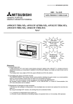
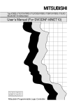
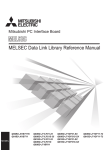
ADVANCED AND EVER ADVANCING
MITSUBISHI ELECTRIC
October 1999
MITSUBISHI
No.113E
NEW PRODUCT RELEASE
GENERAL-PURPOSE
PROGRAMMABLE LOGIC CONTROLLER
Type A1SJ71QLR21,AJ71QLR21* MELSECNET/10 Network
Modules
(For Coaxial loop system)
Type A70BDE-J71QLR23 MELSECNET/10 Interface Board
(For Coaxial loop system)
* AJ71QLR21 will be available soon.
New!
A coaxial loop system, less expensive than the optical loop system and more
reliable than the coaxial bus system, is possible using a network system with the
PLC.
MELSECNET/10 Network System
(coaxial loop system)
Low price
High reliability
PLC
(control station)
IBM PC/AT compatible PC
(normal station)
AJ71QLR21
A1SJ71QLR21
A70BDE-J71QLR23
PLC
(normal station)
R.SD F.SD
AJ71QLR21
A1SJ71QLR21
A70BDE-J71QLR23
R.SD
IN
F.RD
F.SD
OUT
R.RD
BD808C114G51
The coaxial loop system has the following features compared to the coaxial bus system and optical loop
system.
System name
Coaxial loop
system
Reliability
The faulty station is cut off when the cable
is disconnected or when the normal
station is disconnected, allowing normal
operation with just the operable stations.
(Loop back function)
System structure
As a coaxial cable is used, the system can cost
less than the optical loop system.
Maximum overall distance: 30km
Coaxial bus system
The system stops when the cable is
disconnected or when the normal station
is disconnected.
As a coaxial cable is used, the system can cost
less than the optical loop system.
Maximum overall distance: 500m (Can be
extended up to 2.5km using the repeater module.)
Optical loop system
The faulty station is cut off when the cable
is disconnected or when the normal
station is disconnected, allowing normal
operation with just the operable stations.
(Loop back function)
The signal attenuation is less compared to the
coaxial cable, and the cable is resistant to noise,
so the maximum overall distance is long.
Maximum overall distance: 30km
1. Type A1SJ71QLR21, AJ71QLR21 MELSECNET/10 Network Modules(For Coaxial loop
system)
[Features]
1) An optimum network module, corresponding to the PLC CPU Series and module size being used, can be
selected.
! Control station/normal station/master station network module
Series
QnA series
Module size
Compact
Large
QnA Series
A1SJ71QLR21
AJ71QLR21
2) The MELSECNET/10 network system (coaxial loop system) is structured by mounting the
A1SJ71QLR21/AJ71QLR21 on the PLC's base unit connecting the PLC CPUs with a coaxial cable.
Data can be shared between the PLC CPUs by creating a network using the MELSECNET/10 network
system.
The A1SJ71QLR21/AJ71QLR21 can set the PLC as the control station or normal station.
There is only one control station per network system; all other stations are normal stations.
[Performance specifications]
The performance specifications of the network module are shown below.
Item
Maximum number of
LX/LY
link
LB
points per network
LW
Maximum number of link points
per link
Communication speed
Communication method
Synchronization method
Encoding method
Transmission path format
Transmission format
Maximum number of networks
Maximum number of groups
Number of stations connected
in one network
Station type which can be set
Cable type
Overall
Maximum
distance for
Transmission
one network
distance
Error control system
Transient transmission function
RAS function
Connection cable
Applicable connector
Cable transmission loss
Adjustment standard
Maximum number of installation
modules
CPU type
Input output occupancy points
5VDC internal voltage consumption
Weight
*1:In planning stages
Specifications
A1SJ71QLR21
AJ71QLR21
8192 points
8192 points
8192 points
LW×2+(LB+LY)/8
2000 bytes
10Mbps(equivalent to 20Mbps during multiplex transmission)
Token ring
Frame synchronization
Manchester code
Duplex loop
Conforms to HDLC (frame type)
239
9
64 stations (control station:1, normal station:63)
Control station/Normal station
3C-2V
5C-2V
19.2km(62995 ft.)
(300m(984.3 ft.)between stations)
30km(98430 ft.)
(500m(1640.5 ft.)between stations)
16
12
5
Retries based on CRC(X +X +X +1) and overtime
! N:N communication (data transmission/reception, data read/write, etc.)
! Transient instructions (ZNRD/ZNWR,SEND/RECV,READ/WRITE,REQ)
! Loopback function upon error detection and cable breakage
! Diagnostic function for the host link line check system
! Prevention of system down by transferring the control station
! Error detection using link special relays and link special registers.
! Network monitoring and various diagnostic function
3C-2V, 5C-2V
BNC-P-3-Ni-CAU, BNC-P-5-Ni-CAU(DDK) or equivalent product
Conforms to JIS C 3501
EMC standard, UL standard (To be complied with in near future.)
Maximum of 4
Q2ASCPU(S1)
Q2ASHCPU(S1)
Q2ACPU(S1),Q3ACPU,
Q4ACPU,Q4ARCPU
Special 32 points
1.14A
0.30kg (0.65lb)
- *1
- *1
[List of functions]
The list of network module functions is shown below.
Function
Description
1) Input(X), output(Y), link relay(B), and link register(W) can be accessed via
MELSECNET/10 using the cyclic transmission function.
! The Network module support 8k points independently for each
device.
Data communication functions
! 2,000/1600 bytes are supported for the number of link points per station.
2) N:N communication is possible using the transient transmission function.
! Communication is possible even when cyclic transmission is not being
performed.
! The maximum number of transient transmissions during each link scan can
be specified.
When there is a cable breakage or when a normal station is disconnected, the faulty
Loopback function
station can be separated using duplex loop type coaxial cable, and normal operation
is executed with only the stations that are operable.
Multiplex transmission function
When the coaxial cable is a duplex loop type, the transmission speed can be
(PC to PC Network only)
doubled by making each transmission path independent.
A station disconnected due to an error occurrence can automatically return to the
Automatic return function
system when the faulty section returns to the normal status. this is executed
according to the board information setting.
A test is performed according to the test mode setting. The hardware and loop circuit
Test function
are checked.
1) The error message associated with an error code is displayed.
Self diagnostic function
2) Contents of the error detected in the link special relay or link special register are
stored.
[Product configuration]
Product name
Type A1SJ71QLR21
MELSECNET/10 Network Module
Type AJ71QLR21
MELSECNET/10 Network Module *1
Type
Type code
Remarks
A1SJ71QLR21
1W1204
-
AJ71QLR21
13X212
-
*1:In planning stages
[Manuals]
Manual name
MELSECNET/10 Network Module User’s
Manual(Hardware)
Manual shipment type
IB No.
Type code
Enclosed with
A1SJ71QLR21
IB-0800091
13JQ87
2. Type A70BDE-J71QLR23 MELSECNET/10 Interface Board (For Coaxial loop system)
[Features]
1) An available personal computer can be assembled with the lowcost and high-reliability MELSECNET/10
network system (coaxial loop system).
The A70BDE-J71QLR23 can be mounted in a personal computer to use the personal computer as a
normal station.
2) Test and monitor information related to data link are displayed on the CRT screen.
Operation becomes easy since the data-link testing and monitoring statuses are displayed on the CRT
for IBM PC/AT compatible PC.
3) Various functions are available to accommodat user programming.
Various functions that can be used with Visual C++ and Visual Basic are provided, making it possible to
easily create user program remote control for the PLC CPU as well as reading from and writing to
devices.
4) N:N communication is possible with the transient transmission function.
Normal station PCscan communicate with the PLC on a control station and normal station via data
communication (Q/QnA dedicated instruction), device reading and writing, and so on.
5) Drivers for various operating systems are available.
A variety of drivers are provided to make it easier to construct a system that is compatible with the user’s
environment.
Compatible operating systems:
Windows 95(English Version)
Windows 98(English Version)
Windows NT Workstation 4.0(English Version)
MS-DOS Ver6.2(English Version)
[Performance specifications]
The performance specifications of the A70BDE-J71QLR23 are shown below.
Item
Specifications
LX/LY
LB
LW
Maximum number of link points
per link
Communication speed
Communication method
Synchronization method
Encoding method
Transmission path format
Transmission format
Maximum number of networks
Maximum number of groups
Number of stations connected
in one network
8192 points
8192 points
8192 points
Maximum number of link
points per network
Cable type
Overall distance
for one network
Maximum
Transmission
distance
Error control system
transient transmission function
RAS function
Connection cable
Applicable connector
Cable transmission loss
Applicable standards
Number of boards that can be used
Loading slot
Number of slots occupied
5VDC internal voltage consumption
Weight
LW×2+(LB+LY)/8
2000 bytes
10Mbps(equivalent to 20Mbps during multiplex transmission)
Token ring
Frame synchronization
Manchester code
Duplex loop
Conforms to HDLC (frame type)
239
9
64 stations (control station:1, normal station:63)
3C-2V
5C-2V
19.2km(62995 ft.)
(300m(984.3 ft.)between stations)
30km(98430 ft.)
(500m(1640.5 ft.)between stations)
16
12
5
Retries based on CRC(X +X +X +1) and overtime
! N:N communication (data transmission/reception, data read/write, etc.)
! Loopback function upon error detection and cable breakage
! Diagnostic function for the host link line check system
! Prevention of system down by transferring the control station
! Error detection using link special relays and link special
registers.
! Network monitoring and various diagnostic function
3C-2V, 5C-2V
BNC-P-3-Ni-CAU, BNC-P-5-Ni-CAU(DDK) or equivalent product
Conforms to JIS C 3501
EMC standard, UL standard (To be complied with in near future.)
Maximum of 4 *1,*2
IBM PC/AT compatible PC ISA bus slot
1 slot
1.3A
0.17kg (0.37lb)
*1: The No. of mountable boards is the combination of the A70BDE-J71QLP23, A70BDE-J71QLP23GE,
A70BDE-J71QBR13 and A70BDE-J71QLR23.
*2: When mounting two or more A70BDE-J71QLR23 Board onto the personal computer, do not mount in the
adjacent ISA bus slot. If this is not observed, the coaxial cable cannot be connected.
[List of functions]
The list of network module functions is shown below.
Function
Description
1) Input(X), output(Y), link relay(B), and link register(W) can be accessed via
MELSECNET/10 using the cyclic transmission function.
! The A70BDE-J71QLR23 and unit support 8k points independently for each
device.
Data communication functions
! 2,000 bytes are supported for the number of link points per station.
2) N:N communication is possible using the transient transmission function.
! Communication is possible even when cyclic transmission is not being
performed.
! The maximum number of transient transmissions during each link scan can
be specified.
When there is a cable breakage or when a normal station is disconnected, the
Loopback function
faulty station can be separated using duplex loop type coaxial cable, and normal
operation is executed with only the stations that are operable.
Multiplex transmission function
When the coaxial cable is a duplex loop type, the transmission speed can be
doubled by making each transmission path independent.
A station disconnected due to an error occurrence can automatically return to the
Automatic return function
system when the faulty section returns to the normal status. this is executed
according to the board information setting.
A test is performed according to the test mode setting. The hardware and loop
Test function
circuit are checked.
By the loop monitor setting, the host and other stations can be monitored and a
Loop monitor function
check of the operating status performed.
1) The error message associated with an error code is displayed.
Self diagnostic function
2) Contents of the error detected in the link special relay or link special register are
stored.
[Data link functions]
The following functions can be used from the application software to access the data in the PLC.
Function name
Description
Function name
Description
mdOpen
Opens a communication line.
mdBdRst
Resets the board itself.
mdClose
Closes a communication line.
mdBdModSet
Sets the board itself.
mdSend
Performs batch write of devices.
mdBdModRead
Reads the board itself.
mdReceive
Performs batch read of devices.
mdRandW
Writes devices randomly.
mdRandR
Reads devices randomly.
mdDevSet
Sets a bit device.
mdDevRst
mdTypeRead
Resets a bit devices.
Reads the type of PLC CPU.
mdControl
Remote RUN/STOP/PAUSE.
mdInit
Refreshes the PLC device address.
mdBdLedRead
mdBdSwRead
mdBdVerRead
Reads the LED information of the board
itself.
Reads the switch status of the board itself.
Reads the version information of the board
itself.
mdSend
*1
Sends data (SEND function).
mdReceive
*1
Receives data (RECV function).
*1:Q/QnA dedicated instruction
[Utility]
Various MELSECNET/10 utilities for monitoring are provided when the A70BDE-J71QLR23 is connected to the
MELSECNET/10 network system.
1) MELSECNET/10 utility for Windows 95/98/NT Workstation 4.0
Menu
Description
Card list
Displays information on the hardware connected to the A70BDE-J71QLR23.
Card information
Displays and sets various information regarding the mounted A70BDE-J71QLR23.
Loop monitor
Monitors the line status of the local station.
Each station status
Displays the communication status and loop status of each station.
Error history monitor
Version
Displays the history of the loop errors, communication errors and transient transmission
errors.
Displays the MELSECNET/10 utility version.
1) Monitors the local station and remote station devices.
Device monitor utility
Error viewer
*1
2) Writes the local station and remote station devices.
Displays the date of error occurrence, error No. and message details.
*1:This can be used only with the Windows 95/98 OS.
When using the Windows NT Workstation 4.0 OS, the data is registered in the event viewer.
2) MELSECNET/10 utility for DOS
Menu
Description
1) Indicates status of A70BDE-J71QLR23.
Board information
2) Performs mode setting and board reset.
Network setting
Sets the routing parameter.
1) Displays host’s communication status, link scan time, setting, and error information.
Network monitor
2) Displays information of each station.
Performs loop test, setting verification test, station order verification test, and
Network diagnosis
communication test.
1) Performs device monitor for host and other stations.
Device monitor
2) Writes to device in the host and other stations.
Information
Displays setting status of A70BDE-J71QLR23.
[Operating environment]
The operating environment for A70BDE-J71QLR23 is shown below.
Item
Description
IBM PC/AT compatible PC with Pentium 133MHz or higher, one or more ISA bus slots
IBM PC/AT compatible PC
(half size), and running Windows 95 (English version), Windows 98 (English version),
Windows NT Workstation 4.0 (English version), or MS-DOS Ver6.2 (English version) *1
Any one of the following: Windows 95(English version), Windows 98(English version),
Operating system
Windows NT Workstation 4.0(English version), MS-DOS Ver6.2(English version)
MS-DOS Ver6.2
Visual C++ Ver1.5(English version)
Programming
Windows 95
Visual Basic Ver4.0(English version), Visual C++ Ver4.2(English version), Visual Basic
language
Windows 98
Ver5.0(English version), Visual C++ Ver5.0(English version), Visual Basic
Windows NT 4.0
Ver6.0(English version), Visual C++ Ver6.0(English version)
Required memory size
32MB or more
Hard disk space
9MB or more
Disk drive
(required when installing the driver)
3.5 inch (1.44MB) floppy disk drive
*1: A multiprocessor PC cannot be used since the drivers are not compatible.
[Product configuration]
Product name
Type A70BDE-J71QLR23
MELSECNET/10 Interface Board
Type
Type code
A70BDE-J71QLR23
1W6009
Remarks
A70BDE-J71QLR23 × 1 set
FD(SW3DNF-MNET10) × 1 set
Manual × 1 set
Software use agreement × 1
Software entry form × 1
[Manuals]
Manual name
Type A70BDE-J71QLP23/A70BDE-J71QLP23GE/
A70BDE-J71QBR13/A70BDE-J71QLR23
MELSECNET/10 Interface Board User’s Manual
Manual shipment type
IB No.
Type code
Enclosed with product
IB-0800035
13JL93
Microsoft Windows, Microsoft Windows NT, Microsoft Visual Basic, Microsoft Visual C++ and MS-DOS are eigther registered
trademarks or trademarks of Microsoft Corporation in the United States and/or other countries.
Other company names or product names found in the text are trademarks or registered trademarks of the respective
companies.
Sales office
Tel/Fax
Mitsubishi Electric Automation Inc.
500 Corporate Woods Parkway Vernon Hills, IL 60061
Tel : 1-847-478-2100
FAX: 1-847-478-0328
Brazil
MELCO-TEC Rep. Com.e Assessoria Tecnica Ltda.
Av. Rio Branco, 123-15 ,and S/1507, Rio de Janeiro, RJ CEP 20040-005, Brazil
Tel : 55-21-221-8343
FAX: 55-21-221-9388
U.K
Mitsubishi Electric Europe B.V. UK Branch
Travellers Lane, Hatfield, Herts., AL10 8XB,UK
Tel : 44-1707-276100
FAX: 44-1707-278695
Germany
Mitsubishi Electric Europe B.V. German Branch
Gothaer Strasse 8 D-40880 Ratingen, GERMANY
South Africa
MSA Manufacturing (Pty) Ltd.
P O Box 39733 Bramley 201 8 Johannesburg, South Africa
Messung Systems Put,Ltd.
Electronic Sadan NO:111 Unit No15, M.I.D.C BHOSARI,PUNE-411026
Tel : 49-2102-486-0
FAX: 49-2102-486-717
Tel : 27-11-444-8080
FAX: 27-11-444-8304
Country/Region
U.S.A
India
Singapore
Mitsubishi Electric Asia Pte, Ltd.
307 ALEXANDRA ROAD #05-01/02, MITSUBISHI ELECTRIC BUILDING SINGAPORE 159943
Tel : 91-212-793130
FAX: 91-212-798108
Tel : 65-470-2480
FAX: 65-476-7439
P.T. Autoteknindo SUMBER MAKMUR
Kompleks Agung Sedayu Propertindo (Harco Mangga Dua)
Blok H No.4 JI Mangga Dua Raya Jakarta Pusat 10730-Indonesia.
F. A. Tech Co.,Ltd.
1138/33-34 Rama 3 Road, Yannawa, Bangkok 10120, Thailand
Tel : 66-2-295-2861
FAX: 66-2-295-2865
Ryoden International Ltd.
10th Floor, Manulife Tower, 169 Electric Road, North Point, HongKong
Tel : 852-2887-8870
FAX: 852-2887-7984
Ryoden International Shanghai Ltd.
3F Block5 Building Automation Instrumentation Plaza 103 Cao Bao Rd. Shanghai 200233 China
Tel : 86-21-6475-3228
FAX: 86-21-6484-6996
Taiwan
Setsuyo Enterprise Co., Ltd.
6F., No.105 Wu-Kung 3rd.RD, Wu-Ku Hsiang, Taipei Hsine, Taiwan R.O.C.
Tel : 886-2-2299-2499
FAX: 886-2-2299-2509
Australia
Mitsubishi Electric Australia Pty. Ltd.
348 Victoria Road, PostalBag, No 2, Rydalmere, N.S.W 2116, Australia
Tel : 61-2-9684-7777
FAX: 61-2-9684-7245
Indonesia
Thailand
Hong Kong
China
99(MEE)
Tel : 62-21-336292
FAX: 62-21-330378
MITSUBISHI ELECTRIC CORPORATION
HEAD OFFICE MITSUBISHI DENKI BLDG. MARUNOUCHI. TOKYO 100-8310. TELEX J24532 CABLE MELCO TOKYO