1
MELSECNET/H
Interface Board
User’s Manual
(Hardware)
Q80BD-J71LP21-25
Q80BD-J71LP21G
Q80BD-J71BR11
Thank you for buying the Mitsubishi general-purpose programmable
logic controller MELSEC Series
Prior to use, please read both this manual and detailed manual
thoroughly and familiarize yourself with the product.
MODEL MNETH-B-SW0-H
MODEL
13JT27
CODE
IB(NA)-0800154-F(0212)MEE
2000 MITSUBISHI ELECTRIC CORPORATION
z SAFETY PRECAUTIONS z
(Always read these instructions before using this equipment.)
Before using this product, please read this manual and the relevant manuals
introduced in this manual carefully and pay full attention to safety to handle the
product correctly.
Precautionary notes in this manual cover only the installation of this product.
For safety precautions on the PLC system, refer to the CPU User's Manual.
In this manual, the safety instructions are ranked as "DANGER" and
"CAUTION".
DANGER
CAUTION
Indicates that incorrect handling may cause hazardous
conditions, resulting in death or severe injury.
Indicates that incorrect handling may cause hazardous
conditions, resulting in medium or slight personal injury or
physical damage.
Note that the
CAUTION level may lead to a serious consequence
according to the circumstances.
Always follow the instructions of both levels because they are important to
personal safety.
Please save this manual to make it accessible when required and always
forward it to the end user.
[INSTALLATION PRECAUTIONS]
CAUTION
z Use the MELSECNET/H board in an environment as described in the
general specifications listed in this operating manual.
If the board is used in an environment outside the ranges described in the
general specifications, it may result in an electric shock, fire,
malfunctioning, damage to or deterioration of the product.
z Always turn off all external power before installing or removing the
MELSECNET/H board. If all power is not turned off, this will result in failure
of the MELSECNET/H board or malfunctioning.
z Securely mount the MELSECNET/H board to the PCI bus slot of the
mounting device. If the MELSECNET/H board is not mounted correctly, this
may lead to malfunctioning, failure or cause the board to fall.
z When mounting the MELSECNET/H board, take care not to become
injured by the components that are installed or surrounding materials.
z Always make sure to touch the grounded metal to discharge the electricity
charged in the body, etc., before touching the MELSECNET/H board.
Failure to do so may cause a failure or malfunctions of the MELSECNET/H
board.
A-1
[WIRING PRECAUTIONS]
DANGER
z Always turn off all external power before performing work such as installing
the MELSECNET/H board and wiring. If all power is not turned off, there is
a risk of electric shock or damage to the product.
z When turning on the power and operating the module after having installed
the MELSECNET/H board and doing the wiring, always attach the cover for
the device module in which the MELSECNET/H board is installed.
There is a risk of electric shock if the module cover is not attached.
CAUTION
z Solder the coaxial cable's connector properly.
Improper soldering may cause the module to malfunction.
z Take care that foreign objects such as chips or wiring debris do not get on
the MELSECNET/H board. This can result in fire, breakdowns or
malfunctioning.
z Insert the communication cable securely into the MELSECNET/H board
connector. After it has been inserted, check to make sure that it is not
being lifted up.
A faulty connection can lead to faulty input or output.
z For the communication cable, specialized skills and tools are required to
connect the plug and cable. The connector plug itself is a custom part.
When purchasing, consult with the nearest Mitsubishi Electric System
Services, Inc.
If the connection is incomplete, this can result in a short, fire or
malfunctioning.
A-2
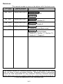
Revisions
*The manual number is given on the bottom left of the back cover.
Print Date
Nov., 2000
Mar., 2001
*Manual Number
IB(NA)-0800154-A
IB(NA)-0800154-B
Jun., 2001
IB(NA)-0800154-C
Feb., 2002
IB(NA)-0800154-D
Jul., 2002
IB(NA)-0800154-E
Dec., 2002
IB(NA)-0800154-F
Revision
First edition
Model addition
Q80BD-J71LP21G
Correction
Section 8.1
Correction
Section 7.1, Section 8.1
Correction
Chapter 3, Chapter 5
Correction
Contact address (Back cover)
Correction
SAFETY PRECAUTIONS,
Section 6.2, Section 7.1, Section 7.2,
Section 8.1, Chapter 9
This manual confers no industrial property rights or any rights of any other
kind, nor does it confer any patent licenses. Mitsubishi Electric Corporation
cannot be held responsible for any problems involving industrial property
rights which may occur as a result of using the contents noted in this manual.
2000 MITSUBISHI ELECTRIC CORPORATION
A-3
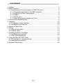
CONTENTS
1. Outline ...........................................................................................................1
2. EMC Directive ................................................................................................2
2.1 Requirements for conformance to EMC Directive .....................................2
2.1.1 Standards applicable to the EMC Directive ........................................3
2.1.2 Installing into the control panel...........................................................3
2.1.3 Cables................................................................................................5
2.1.4 Ferrite core.........................................................................................6
2.1.5 Noise filter (power supply line filter) ...................................................7
3. Performance Specifications ...........................................................................8
4. Handling.......................................................................................................10
4.1 Precautions when handling.....................................................................10
4.2 Installation environment..........................................................................10
5. Names of Each Part .....................................................................................11
6. Wiring...........................................................................................................13
6.1 Optical fiber cable...................................................................................13
6.2 Coaxial cable ..........................................................................................14
7. Installing Software Packages .......................................................................16
7.1 Installation procedures ...........................................................................16
7.2 Icons to be registered ............................................................................17
8. Using the Manual (PDF Data) ......................................................................18
8.1 Procedures for viewing manual...............................................................18
8.2 Operating the manual .............................................................................19
9. External Dimensions ....................................................................................20
A-4
About the Manuals
The following manuals are also related to this product.
In necessary, order them by quoting the details in the tables below.
Related Manuals
Manual No.
(Model code)
Manual name
MELSECNET/H Interface Board User’s Manual
(For SW0DNC-MNETH-B)
The system configuration, software package
installation, uninstallation and each utility's operation
method,
accessible
range,
devices
and
troubleshooting are explained. (Option)
Q corresponding MELSECNET/H Network System
Reference Manual (PLC to PLC network)
The MELSECNET/H network system's system
configuration, performance specifications, functions,
handling, wiring and troubleshooting are explained.
(Option)
Q/QnA/Q4AR
corresponding
MELSECNET/10
Network System Reference Manual
The MELSECNET/10 network system's system
configuration, performance specifications, functions,
handling, wiring and troubleshooting are explained.
(Option)
A70BDE-J71QLP23/A70BDE-J71QLP23GE/
A70BDE-J71QLR13/A70BDE-J71QLR23
MELSECNET/10 Interface Board User’s Manual
(For SW3DNF-MNET10)
The MELSECNET/10 board's system configuration,
performance specifications, functions, handling,
wiring and troubleshooting are explained. (Option)
SH-080128
(13JT25)
SH-080049
(13JF92)
IB-66690
(13JF78)
IB-0800035
(13JL93)
Remarks : MELSECNET/H Interface Board User’s Manual (For SW0DNCMNETH-B) is enclosed with the CD-ROM as a set with the
software package.
A printed version of the manual is available as an option.
Indicate the manual No. (Model code) when placing an order
for a printed version of the manual.
A-5
1. Outline
This manual explains the methods of handling the Q80BD-J71LP21-25/Q80BDJ71LP21G/Q80BD-J71BR11 MELSECNET/H interface board (hereinafter
referred to as the MELSECNET/H board). (Special models are abbreviated as
Q80BD-J71LP21-25, Q80BD-J71LP21G or Q80BD-J71BR11.)
The MELSECNET/H board can be used as a control station or normal station in
the MELSECNET/H network system (PLC to PLC network).
The MELSECNET/H board cannot be used in the remote I/O network.
Unpack the product and confirm that the following products are enclosed.
Part name
Q80BDJ71LP21-25
Quantity
Q80BDJ71LP21G
Q80BDJ71BR11
1
-
-
-
1
-
-
-
1
1
1
1
1
1
1
1
1
1
1
Type Q80BD-J71LP21-25
MELSECNET/H Interface Board
Type Q80BD-J71LP21G
MELSECNET/H Interface Board
Type Q80BD-J71BR11
MELSECNET/H Interface Board
SW0DNC-MNETH-B MELSECNET/H
software package (CD-ROM)
MELSECNET/H Interface Board
User's Manual (Hardware)
F-type connector
Software License Agreement
Important
A terminator is required at each end station of the network when using the
coaxial bus type network system.
The terminator is not enclosed with the Q80BD-J71BR11, and must be
prepared by the user.
Refer to section "6.2 Coaxial cable" for details on the terminator.
1
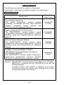
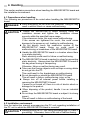
2. EMC Directive
For the products sold in European countries, the conformance to the EMC
Directive, which is one of the European Directives, has been a legal obligation
since 1996.
Manufacturers who recognize their products must conform to the EMC Directive
are required to declare that their products conform to these Directives and put a
"CE mark" on their products.
2.1 Requirements for conformance to EMC Directive
The EMC Directive specifies that products placed on the market must "be so
constructed that they do not cause excessive electromagnetic interference
(emissions) and are not unduly affected by electromagnetic interference
(immunity) ". The applicable products are requested to meet these
requirements. The sections 2.1.1 through 2.1.5 summarize the precautions on
conformance to the EMC Directive of the machinery constructed using the
MELSECNET/H Board.
The details of these precautions has been prepared based on the control
requirements and the applicable standards . However, we will not assure that
the overall machinery manufactured according to these details conforms to the
above-mentioned directives. The method of conformance to the EMC directive
and the judgment on whether or not the machinery conforms to the EMC
Directive must be determined finally by the manufacturer of the machinery.
2
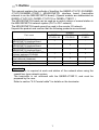
2.1.1 Standards applicable to the EMC Directive
The standards applicable to the EMC Directive are listed below.
All test items are carried out with the product mounted in a CE mark compliant
personal computer.
Specification
Test item
EN55011
Radiated noise
EN50081-2 :
1995
EN55011
Conducted
noise
EN61000-4-2
Electrostatic
immunity
EN61131-2 :
1996
EN61000-4-4
Fast
transient
burst noise
EN61000-4-3
Radiated
field
AM modulation
EN61000-4-12
Damped
oscillatory wave
immunity
Test details
Electromagnetic
emissions from the
product
are
measured.
Electromagnetic
emissions from the
product
to
the
power
line
is
measured.
Immunity test in
which
static
electricity is applied
to the cabinet of the
equipment.
Immunity test in
which burst noise is
applied
to
the
power line and
signal lines.
Immunity test in
which
field
is
irradiated to the
product.
Immunity test in
which a damped
oscillatory wave is
superimposed on
the power line.
Standard value
30M-230MHz QP : 30dB µ V/m
(30 m in measurement range) *1
230M-1000MHz QP : 37 dB µ V/m
(30 m in measurement range)
150k-500kHz QP: 79 dB,
Mean: 66 dB *1
500k-30MHz QP: 73 dB,
Mean: 60 dB
15kV Aerial discharge
Power line: 2kV
Digital I/O (24V or higher): 1kV
(Digital I/O (24V or less)) > 250V
(Analog I/O, signal lines) > 250V
10V/m, 26-1000MHz,
80%AM modulation@1kHz
Power line: 1kV
Digital I/O (24V or higher): 1kV
*1: QP : Quasi-peak value, Mean : Average value
2.1.2 Installing into the control panel
Installing this module into the control panel is effective not only for ensuring
safety, but also for shielding noise generated from the personal computer by
the control panel.
(1) Control cabinet
(a) Use a conductive control cabinet.
(b) When attaching the control cabinet's top plate or base plate, mask
painting and weld so that good surface contact can be made between
the cabinet and plate.
(c) To ensure good electrical contact with the control cabinet, mask the
paint on the installation bolts of the inner plate in the control cabinet so
that contact between surfaces can be ensured over the widest
possible area.
(d) Earth the control cabinet with a thick wire so that a low impedance
connection to ground can be ensured even at high frequencies.
3
(e) Holes made in the control cabinet must be 10 cm (3.94 in.) diameter or
less. If the holes are 10 cm (3.94 in.) or larger, radio frequency noise
may be emitted.
In addition, because radio waves leak through a clearance between
the control panel door and the main unit, reduce the clearance as
much as practicable.
The leakage of radio waves can be suppressed by the direct
application of an EMI gasket on the paint surface.
Our tests have been carried out on a panel having the damping
characteristics of 37 dB max. and 30 dB mean (measured by 3 m
method with 30 to 300 MHz).
Maker name
Series type
KITAGAWA INDUSTRIES CO., LTD.
US series
ZIPPERTUBING (JAPAN) LTD.
71TS series
SEIWA ELECTRIC MFG CO., LTD.
E02SA
All tests carried out by Mitsubishi are carried out with a panel having
maximum 37dB, average 30dB (30 to 300MHz, 3m dimension
measurement) damping characteristics.
(2) Leading the power and earth wires
Lead the personal computer's earth and power wires as indicated below.
(a) Provide an earth point for the control panel near the personal
computer's power supply, and earth the personal computer's FG
terminal (FG: frame ground) with an earth wire (electric wire for
earthing) as thick and short as possible (wire length should be approx.
30cm or shorter).
The FG terminal acts to relieve noise generated in the personal
computer to the earth, so the earth wire impedance must be as low as
possible.
As the earth wire acts to relieve the noise, the wire itself has a large
noise element. Thus, the short wire acts to prevent the earth wire from
functioning as an antenna.
(b) The earth wire led from the earthing point must be twisted with the
power supply wires. By twisting with the earthing wire, noise flowing
from the power supply wires can be relieved to the earthing. However,
if a filter is installed on the power supply wires, the wires and the
earthing wire may not need to be twisted.
4
2.1.3 Cables
The cables led from the control panel have a higher harmonic noise element.
Thus, the cables act as antennas outside the control panel and radiate noise.
Always use shielded cables for those cables led out of the control panel.
The shielded cable is also effective for increasing the noise withstand level.
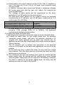
(1) Treating the shielded cable's shield
(a) Treat the shield near the outlet from the control panel.
If the earth point is not near the outlet, the cables after the earth point
will cause electromagnetic induction, and will generate a higher
harmonic noise.
(b) Peel part of the shielded cable's sheath, and earth a wide section of
the exposed shielded section against the control panel.
Clamp fittings can be used as shown below. Note that the painting on
the inner side of the control panel, against which the clamp fitting is
contacted, must be masked.
Screw
Clamp fitting
Shield section
Paint mask
Shielded cable
Note) The method of earthing by soldering a wire onto the shield section
of the shielded cable as shown below is not recommended. The
high frequency impedance will increase and the shield will be
ineffective.
Shielded cable
Wire
Crimp terminal
5
(2) Treatment of the coaxial cable ground
(a) Always use a double-shielded coaxial cable (MITSUBISHI CABLE :
5C-2V-CCY) for the coaxial cables Q80BD-J71BR11. Radiated noise
in the range of 30MHz or higher can be suppressed by use of the
double-shielded coaxial cables. Earth the double-shielded coaxial
cable by connecting its outer shield to the ground.
Ground here.
(b) Attach a ferrite core to the double -shielded coaxial cable connected to
the Q80BD-J71BR11.
The ferrite core should be attached on each cable near the outlet of
the control panel.
Refer to section "2.1.4 Ferrite core" for details.
2.1.4 Ferrite core
A ferrite core has the effect of reducing radiated noise in the 30 M Hz to 100 M
Hz band.
It is not required to fit ferrite cores to cables, but it is recommended to fit ferrite
cores if shield cables pulled out of the enclosure do not provide sufficient
shielding effects.
It should be noted that the ferrite cores should be fitted to the cables in the
position immediately before they are pulled out of the enclosure. If the fitting
position is improper, the ferrite will not produce any effect.
y Ferrite core
Type: ZCAT3035-1330 (TED ferrite core)
6
2.1.5 Noise filter (power supply line filter)
A noise filter is a component which has an effect on conducted noise.
It is not required to fit the noise filter to the power supply line, but fitting it can
further suppress noise.
(The noise filter has the effect of reducing conducted noise of 10 M Hz or less.)
The precautions required when installing a noise filter are described below.
(1) Do not bundle the wires on the input side and output side of the noise
filter. When bundled, the output side noise will be induced into the input
side wires from which the noise was filtered.
Input side
(power supply side)
Input side
(power supply side)
Introduction
Filter
Filter
Output side
(device side)
(a) The noise will be included
when the input and output wires
are bundled.
Output side
(device side)
(b) Separate and lay the input
and output wires.
(2) Earth the noise filter earthing terminal to the control cabinet with the
shortest wire possible (approx. 10 cm (3.94 in.)).
Remarks
Reference noise filters are shown below.
Noise filter type
FN343-3/01
FN660-6-06
ZHC2203-11
Maker name
SCHAFFNER
TDK
7
Rated current
3A
6A
3A
Rated voltage
250V
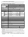
3. Performance Specifications
The performance specifications of the MELSECNET/H board are given below.
(1) Q80BD-J71LP21-25, Q80BD-J71LP21G
Item
Maximum number LX/LY
LB
of link points per
network
LW
Maximum number of links
per station
Communication speed
Number of stations
connected per network
Connection cable
Overall cable distance
At 10Mbps
communication
speed
Distance
between
*3
stations
At 25Mbps
communication
speed
Maximum number of
networks
Maximum number of groups
Transmission path type
Communication method
Synchronization method
Coding method
Transmission format
Error control method
RAS function
Transient transmission
Special cyclic transmission
Number of mountable
boards
Mounting slot
Occupied slot
5VDC internal current
consumption
Weight
Specifications
Q80BD-J71LP21-25
Q80BD-J71LP21G
8192 points
*1
16384 points (During MELSECNET/10 mode : 8192 points)
16384 points (During MELSECNET/10 mode: 8192 points)
((LY+LB)/8+(2×LW)) ≤ 2000 bytes
10Mbps/25Mbps*2
10Mbps
64 stations (one control stations, 63 normal stations)
Optical fiber cable
30km (98430ft.)
SI optical cable
:500m (1640.5 ft.)
H-PCF optical cable
:1km (3281 ft.)
GI optical cable :
Broad-band H-PCF optical cable :1km (3281 ft.)
2km (6562 ft.)
QSI optical cable
:1km (3281 ft.)
SI optical cable
:200m (656.2 ft.)
H-PCF optical cable
:400m (1312.4 ft.)
Broad -band H-PCF optical cable :1km (3281 ft.)
QSI optical cable
:1km (3281 ft.)
239
32 (During MELSECNET/10 mode: 9)
Double loop
Token ring method
Frame synchronization method
NRZI coding (Non Return to Zero Inverted)
HDLC compliant (frame format)
CRC (X16 + X12 + X5 + 1) and retry with overtime
Automatic return function, loop back function, control station shift
function, etc.
N:N communication
Low-speed cyclic transmission
Maximum 4 boards *4
PCI bus slot (half-size)
1 slot
0.46 A
0.45 A
0.10 kg
0.11 kg
*1: The mode is set with the MELSECNET/H utility.
Refer to the "MELSECNET/H Interface Board User's Manual (For SW0DNC-MNETH-B)"
for details.
*2: The Q80BD-J71LP21-25 communication speed is set with the MELSECNET/H utility.
Refer to the "MELSECNET/H Interface Board User's Manual (For SW0DNC-MNETH-B)"
for details.
*3: There are limits to the types of cables that can be used for the optical fiber cable. Refer to
section "6.1 Optical fiber cable" for details.
*4: The number of mountable boards is the total of the MELSECNET/H boards and
MELSECNET/10
boards
(A70BDE-J71QLP23(GE)/A70BDE-J71QBR13/A70BDEJ71QLR23).
8
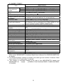
(2) Q80BD-J71BR11
Specifications
Q80BD-J71BR11
Item
Maximum number LX/LY
of link points per
LB
network
LW
Maximum number of links per
station
Communication speed
Number of stations connected
per network
Connection cable
Overall cable distance
Distance between stations *2
Maximum number of
networks
Maximum number of groups
Transmission path type
Communication method
Synchronization method
Coding method
Transmission format
Error control method
8192 points
16384 points (During MELSECNET/10 mode*1: 8192 points)
16384 points (During MELSECNET/10 mode: 8192 points)
((LY+LB)/8+(2×LW)) ≤ 2000 bytes
10Mbps/25Mbps*2
32 stations (one control stations, 31 normal stations)
Coaxial cable 5C-2V, 3C-2V or equivalen
500m (1640.5ft.) (5C-2V), 300m (984.3ft.) (3C-2V)
The distance can be extended up to 2.5km (8202.5 ft.) by
using a repeater module (A6BR10, A6BR10-DC).
500m (1640.5ft.) (5C-2V), 300m (984.3ft.)(3C-2V)
239
32 (During MELSECNET/10 mode: 9)
Single bus
Token bus method
Frame synchronization method
NRZI coding (Non Return to Zero Inverted)
Manchester compliant
CRC (X16 + X12 + X5 + 1) and retry with overtime
Automatic return function, compliant, control station shift
RAS function
function, etc.
Transient transmission
N:N communication
Special cyclic transmission
Low-speed cyclic transmission
Number of mountable boards Maximum 4 boards *3
Mounting slot
PCI bus slot (half-size)
Occupied slot
1 slot
5VDC internal current
0.67 A
consumption
Weight
0.11 kg
*1: The mode is set with the MELSECNET/H utility.
Refer to the "MELSECNET/H Interface Board User's Manual (For SW0DNC-MNETH-B)"
for details.
*2: The distance between stations is limited by the cable type and number of stations. Refer
to the section "6.2 Coaxial cable" for details.
*3: The number of mountable boards is the total of the MELSECNET/H boards and
MELSECNET/10
boards
(A70BDE-J71QLP23(GE)/A70BDE-J71QBR13/A70BDEJ71QLR23).
9
4. Handling
This section explains precautions when handling the MELSECNET/H board and
the installation environment.
4.1 Precautions when handling
The following are precautions to be noted when handling the MELSECNET/H
board.
z While energizing, do not touch the connector. Doing so may
DANGER
result in electric shock or cause malfunctioning.
CAUTION z Fasten the MELSECNET/H board securely using the
installation screws and tighten the installation screws
securely within the specified torque range.
If the screws are loose, this may cause malfunctioning.
If the screws are tightened too much, this could cause
damage to the screws or unit, leading to malfunctioning.
z Do not directly touch the conductive section of the
MELSECNET/H board. Doing so could result in
malfunctioning or breakdown of the MELSECNET/H board.
z Handle the MELSECNET/H board in a location where there
is no static electricity.
Static electricity could result in failure or malfunctioning.
z The MELSECNET/H board is packed in a bag for preventing
static electricity. Always place the MELSECNET/H board in
this bag when storing or transporting.
Otherwise, failure or malfunctioning may result.
z Take care that foreign objects such as chips or wiring debris
do not get into the PC.
This could result in fire, breakdowns or malfunctioning.
z Do not dismantle or rebuild the MELSECNET/H board.
This will result in failure, malfunctioning, injury or fire.
z Always turn off all external power before installing or
removing the MELSECNET/H board.
If power is not turned off, there is a risk of electric shock or
damage to the product.
z When disposing of the product, handle it as an industrial
waste.
z Do not drop the MELSECNET/H board or subject it to strong
impact.
This will result in failure or malfunctioning of the board.
4.2 Installation environment
See the instruction manual accompanying the PC unit regarding installation of
the PC unit in which the MELSECNET/H board is mounted.
CAUTION z Always ground the PC unit using grounding type D (Class 3
grounding). Otherwise, there is the risk of malfunctioning.
10
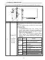
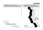
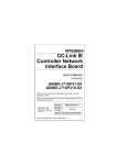
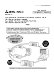
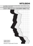
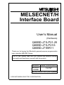
5. Names of Each Part
The names of each MELSECNET/H board part are explained in this section.
1)
L
RUN ERR.
SD
RD
L
RUN ERR.
SD
RD
IN
3)
OUT
Number
Name
Display LED
1)
L
RUN ERR.
SD RD
2)
Details
This indicates the MELSECNET/H board operation
status.
The LED lighting status include the normal mode
and error mode.
(1) Normal mode
If a communication error, etc., occurs in the
normal mode, judge the error by reading the
status of the LED on the MELSECNET/H Utility's
"Board Information" screen.
Refer to the "MELSECNET/H Interface Board
User's Manual (For SW0DNC-MNETH-B)" for
details on the " Board Information" scene's LED
statuses.
LED
Status
Details
name
A WDT error has occurred, or
OFF
the board is being reset.
RUN
The board is operating
ON
normally.
A communication error has
OFF
not occurred.
L ERR.
A communication error has
ON
occurred.
OFF
Data has not been received.
SD
ON
Data is being transmitted.
OFF
Data has not been received.
RD
ON
Data is being transmitted.
11
Number
Name
Display LED
1)
L
RUN ERR.
SD RD
Details
(2) Error mode
When the RUN LED is flickering, the LED display
will change to the error mode.
If an error occurs in the error mode, check the
details of the error with the Error Viewer or Event
Viewer.
Refer to the "MELSECNET/H Interface Board
User's Manual (For SW0DNC-MNETH-B)" for
details.
LED
Status
Details
name
The error mode has been
Flicker
entered.
RUN
ON
No error
OFF
OS
starting
error
has
OFF
occurred.
L ERR.
OS starting error has not
ON
occurred.
Driver compatibility error has
OFF
occurred.
SD
Driver compatibility error has
ON
not occurred.
OFF
PCI bus error has occurred.
RD
PCI bus error has not
ON
occurred.
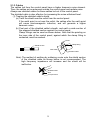
This connector is used to connect the optical fiber
cable.
(1) The cable terminal has the following type of
configuration.
(Board top)
LED
L
RUN ERR.
SD
RD
IN
2)
Optical fiber
cable
connection
connector
IN Reverse loop transmission
IN Forward loop reception
Optical fiber cable
connection cable
OUT
OUT Forward loop transmission
OUT Reverse loop reception
(2) Refer to the "MELSECNET/H Interface Board
User's Manual (For SW0DNC-MNETH-B)" for
details on wiring the optical fiber cable.
12
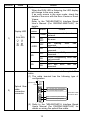
Number
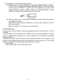
3)
Name
Coaxial
cable
connection
connector
Details
This connector is used to connect the coaxial cable.
(1) The cable terminal has the following type of
configuration.
L
RUN ERR.
(Board top)
LED
SD RD
Coaxial cable
connection connector
(2) Refer to the "MELSECNET/H Interface Board
User's Manual (For SW0DNC-MNETH-B)" for
details on wiring the coaxial cable.
6. Wiring
The precautions for connecting the cable to the MELSECNET/H board are
given below.
Remarks
Refer to the "MELSECNET/H Interface Board User's Manual (For
SW0DNC-MNETH-B)" for details on the wiring method.
6.1 Optical fiber cable
The precautions for connecting the optical fiber cable with the Q80BDJ71LP21-25 and Q80BD-J71LP21G in an optical loop system are given below.
(1) Precautions for connections
(a) The distance between stations varies depending on the type of optical
fiber cable used.
Type
Distance between stations (m)
Q80BD-J71LP21-25
Q80BD-J71LP21G
10Mbps(fixed)
10Mbps
25Mbps
500 (1640.5 ft.) 200 (656.2 ft.)
300 (984.3 ft.)
100 (328.1 ft.)
500 (1640.5 ft.) 200 (656.2 ft.)
1000 (3281 ft.) 400 (1312.4 ft.) Not allowed
SI type optical fiber L type
cable(Old type: A-2P- ) H type
SI optical fiber cable
H-PCF optical fiber cable
Broad-band H-PCF optical fiber
1000 (3281 ft.)
cable
QSI optical fiber cable
1000 (3281 ft.)
GI optical fiber cable
Not allowed
1000 (3281 ft.)
1000 (3281 ft.)
Not allowed
2000 (6562 ft.)
(b) When connecting an optical fiber cable, the following restrictions on
the bending radius must be observed. Please confirm bending radius
of the cable with the cable used.
13
(c) Please maintain the optical fiber cable permissible bending radius with
a checking tool.
Enquiries for the checking tool for optical fiber cable bending radius
maintenance are handled by Mitsubishi Electric System Service
Corporation. Please contact Mitsubishi Electric System Service
Corporation for detail.
(d) When laying the opticalfiber cable, do not touch the fiber core of the
cable connector or module connector, or let dirt or dust collect on it.
If oil from the hands, dirt or dust should adhere to the core, the
transmission loss will increase, causing a malfunction in the data link.
(e) When attaching or detaching the opticalfiber cable to/from the module,
hold the cable connector securely with the hands.
(f) Connect the cable connector and module connector securely until you
hear a "click" sound.
6.2 Coaxial cable
The precautions for connecting the coaxial cable with the Q80BD-J71BR11 in a
coaxial bus system are given below.
(1) Precautions for connections
(a) Limits to station-to-station cable length
1) The cable used to connect networks must have the following
lengths according to the number of connected stations.
When using a cable length other than that shown below, a
communication error may occur.
Number of connected stations
2 to 9 stations
10 to 33 stations
Station-to-station cable length
Cable type
3C-2V
5C-2V
3C-2V
5C-2V
× (A cable less than 1m long cannot
0 to 1m (0 to 3.28ft.)
be used.)
{
{
{
{
1 to 5m (3.28 to 16.41ft.)
{
{
5 to 13m (16.41 to 42.65ft.)
×
×
{
{
{
{
13 to 17m (42.65 to 55.78ft.)
{
{
17 to 25m (55.78 to 82.03ft.)
×
×
{
{
{
{
25 to 300m (82.03 to 984.3ft.)
{
{
300 to 500m (82.03 to 1640.5ft.)
×
×
{ : Usable × : Not usable
2) If the number of stations may increase when the system is
expanded, etc., lay the wires beforehand taking precaution 1)
above into consideration.
3) When using a repeater module (models A6BR10 or A6BR10-DC),
use the station-to-station cable length indicated by "10 to 33"
stations, regardless of the number of stations connected or the
number of repeater modules.
14
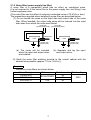
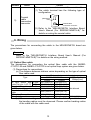
(b) Precautions for laying cables
1) Install the coaxial cables at least 100 mm (3.94 ft.) away from other
power cables and control cables.
2) Consider wiring using double-shielded coaxial cable in places that
are subject to large amounts of noise.
Double shielded coaxial cable
Mitsubishi Cable ... 5C-2V-CCY
Grounding
The 5C-2V connector plug is applicable to double-shielded coaxial
cable.
Contact the 5C-2V connector plug to the coaxial cable inside a
double-shielded coaxial cable. Ground the shielded part outside a
double-shielded coaxial cable as shown in the above figure.
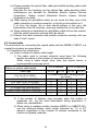
(c) When connecting a coaxial cable, the following restrictions on the
bending radius must be observed.
Cable type
3C-2V
5C-2V
Allowable bending radius
r [mm (in.)]
23 (0.91)
30 (1.18)
Connector
A [mm (in.)]
A
55 (2.17)
r
(d) Do not pull any of the connected coaxial cables.
This will cause a faulty contact, cable disconnection, or damage to the
module.
(e) Make sure to connect a terminal resistor to both terminal stations of
the coaxial bus type network system.
(f) The F-type connector may deposit white oxides depending on the
working environment. This will not form at the fitting section, and thus
poses no functional problems.
(2) Terminal resistor
The coaxial bus-type network system requires terminal resistors
(A6RCON-R75) at both terminal stations of the network. The user should
arrange for terminal resistors, since the Q80BD-J71BR11 does not come
with terminal resistors.
15
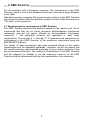
7. Installing Software Packages
The methods of installing the software package and the registered icons are
explained in this section.
Refer to the "MELSECNET/H Interface Board User's Manual (For SW0DNCMNETH-B)" for details on uninstalling the software and on installing by copying
onto an FD.
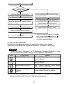
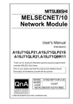
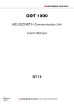
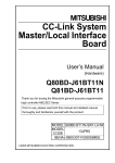
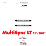
7.1 Installation procedures
Refer to the "MELSECNET/H Interface Board User's Manual (For SW0DNCMNETH-B)" for detailed installation procedures.
Point
(1) A multi-processor compatible personal computer cannot be used as the
drivers are not compatible.
Refer to the "MELSECNET/H Interface Board User's Manual (For
SW0DNC-MNETH-B)" for details on the working environment.
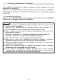
(2) Log on as the user who has the Administrator attributes, when any of the
following OSs is used.
Microsoft Windows NT Workstation Operating System Version 4.0
Microsoft Windows 2000 Professional Operating System
Microsoft Windows XP Professional Operating System
(3) Make sure to close other applications running on Windows (including
resident software such as antivirus software) before installation.
(4) Remove all applications that are included in the Start up menu, then
restart PC before installing.
(5) When the installation fails to complete successfully, and if software
packages can be uninstalled, execute uninstall.
(6) If you want to reinstall the software package, turn off the personal
computer after uninstalling the software package, them turn the personal
computer back on and reinstall the software package.
16
Start
Is the personal
computer power
ON?
No
Yes
Install SW0DNC-MNETH-B (utility).
Mount the MELSECNET/H board onto the
personal computer.
Turn OFF the personal computer power.
Turn the personal computer power ON.
Mount the MELSECNET/H board onto the
personal computer.
Install SW0DNC-MNETH-B (driver). *1
Install SW0DNC-MNETH-B (utility).
Turn the personal computer power ON.
Install SW0DNC-MNETH-B (driver). *1
Completed
*1: The driver does not need to be installed
when using Microsoft Windows NT
Workstation Operating System Version
4.0 as the operating system.
R
R
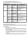
7.2 Icons to be registered
Installing the software packages will register the icons shown below.
The icons shown below are registered in [Start] - [Program] - [MELSEC].
Remarks
When Microsoft Windows XP Professional Operating System is used,
the icons are registered to [Start] - [All Programs] - [MELSEC].
Icon
Utility name
MELSECNET/H Utility
Details
The MNETH Utility starts when this
icon is clicked.
Error Viewer *1
The Error Viewer opens when this
icon is clicked.
Device Monitor Utility
The Device Monitor Utility starts
when this icon is clicked.
The Communication function HELP
opens when this icon is clicked.
MELSEC Communication
Function
HELP
*1: This utility is compatible only with the Microsoft Windows 95 Operating
System and Microsoft Windows 98 Operating System.
17
8. Using the Manual (PDF Data)
The MELSECNET/H Interface Board User's Manual (For SW0DNC-MNETH-B)
is enclosed in the same CD-ROM as the SW0DNC-MNETH-B MELSECNET/H
software package.
The operating manuals may either be used by reading them directly from the
CD-ROM or by installing them on the HD. (They can be used at the user's
option.) The manuals are in the form of PDF data which can be viewed using
Acrobat Reader of Adobe Systems, Inc.
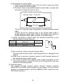
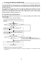
8.1 Procedures for viewing manual
The following explains the procedure up to manual reading and details of the
Manual folder.
(1) Procedure up to manual reading
Designate the CD-ROM drive with My Computer or
Explorer.
R
Is Acrobat Reader
installed in the personal
computer.
Yes
No
Double-click on ar505***.exe in "acrobat", and
install Acrobat Reader. *1
R
R
Start Acrobat Reader, and agree to the Software
License Agreement. *2
Yes
Install the manual data
onto the HD.
Copy ***.pdf into the C:\MESLEC directory.
No
Double-click on ***.pdf in "Manual".
View the manual.
*1: 8MB of open space is required in the hard disk.
*2: The PDF data in the "Manual" folder can be viewed by "Agreeing" to the Software License
Agreement.
18
(2) Details of the Manual folder
For details on the contents of the Manual folder, refer to readme.txt in the
CD-ROM.
The storage location of readme.txt is as follows:
Manual
Japanese
readme.txt (The following explains the files in theJapanese folder.)
English
readme.txt (The following explains the files in the English folder.)
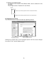
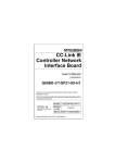
8.2 Operating the manual
The following screen is used to browse any operating manual.
Bookmark section
Manual display section
Clicking any contents item in the "bookmark section" with the mouse changes
the screen in the "manual display section".
19
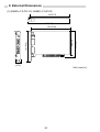
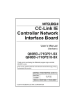
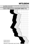
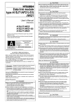
9. External Dimensions
(1) Q80BD-J71LP21-25, Q80BD-J71LP21G
147(5.73)
153(5.97)
141(5.50)
L
RUN ERR.
SD
RD
99(3.86)
121(4.72)
OUT
90(3.51)
IN
19
(0.74)
Unit: mm (in.)
20
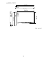
(2) Q80BD-J71BR11
147(5.73)
153(5.97)
141(5.50)
L
RUN ERR.
99(3.86)
90(3.51)
RD
121(4.72)
SD
19
(0.74)
Unit: mm (in.)
21
Warranty
Mitsubishi will not be held liable for damage caused by factors found not to be the cause of
Mitsubishi; machine damage or lost profits caused by faults in the Mitsubishi products;
damage, secondary damage, accident compensation caused by special factors
unpredictable by Mitsubishi; damages to products other than Mitsubishi products; and to
other duties.
For safe use
y This product has been manufactured as a general-purpose part for general industries, and
has not been designed or manufactured to be incorporated in a device or system used in
purposes related to human life.
y Before using the product for special purposes such as nuclear power, electric power,
aerospace, medicine or passenger movement vehicles, consult with Mitsubishi.
y This product has been manufactured under strict quality control. However, when installing
the product where major accidents or losses could occur if the product fails, install
appropriate backup or failsafe functions in the system.
Country/Region Sales office/Tel
U.S.A
Mitsubishi Electric Automation Inc.
500 Corporate Woods Parkway Vernon
Hills, IL 60061
Tel : +1-847-478-2100
Brazil
MELCO-TEC Rep. Com.e Assessoria
Tecnica Ltda.
AV. Paulista 1471, Conj. 308,
Sao Paulo City, Sao Paulo State,
Brazil
Tel : +55-11-283-2423
Germany
Mitsubishi Electric Europe B.V. German
Branch
Gothaer Strasse 8 D-40880 Ratingen,
GERMANY
Tel : +49-2102-486-0
U.K
Mitsubishi Electric Europe B.V. UK
Branch
Travellers Lane, Hatfield, Herts., AL10
8XB,UK
Tel : +44-1707-276100
Italy
Mitsubishi Electric Europe B.V. Italian
Branch
Centro Dir. Colleoni, Pal. Perseo-Ingr.2
Via Paracelso 12, 20041 Agrate B.,
Milano, Italy
Tel : +39-039-6053344
Spain
Mitsubishi Electric Europe B.V. Spanish
Branch
Carretera de Rubi 76-80
08190 - Sant Cugat del Valles,
Barcelona, Spain
Tel : +34-93-565-3131
France
Mitsubishi Electric Europe B.V. French
Branch
25 Boulevard des Bouvets, F-92741
Nanterre Cedex, France
TEL: +33-1-5568-5568
South Africa
Circuit Breaker Industries LTD.
Tripswitch Drive, Elandsfontein Gauteng,
South Africa
Tel : +27-11-928-2000
Country/Region Sales office/Tel
Hong Kong
Ryoden Automation Ltd.
10th Floor, Manulife Tower, 169 Electric
Road, North Point, HongKong
Tel : +852-2887-8870
China
Ryoden Automation Shanghai Ltd.
3F Block5 Building Automation
Instrumentation Plaza 103 Cao Bao Rd.
Shanghai 200233 China
Tel : +86-21-6475-3228
Taiwan
Setsuyo Enterprise Co., Ltd.
6F., No.105 Wu-Kung 3rd.RD, Wu-Ku
Hsiang, Taipei Hsine, Taiwan
Tel : +886-2-2299-2499
Korea
HAN NEUNG TECHNO CO.,LTD.
1F Dong Seo Game Channel Bldg.,
660-11, Deungchon-dong Kangsec-ku,
Seoul, Korea
Tel : +82-2-3660-9552
Singapore
Mitsubishi Electric Asia Pte, Ltd.
307 ALEXANDRA ROAD #05-01/02,
MITSUBISHI ELECTRIC BUILDING
SINGAPORE 159943
Tel : +65-6473-2308
Thailand
F. A. Tech Co.,Ltd.
898/28,29,30 S.V.City Building,Office
Tower 2,Floor 17-18 Rama 3 Road,
Bangkpongpang, Yannawa,
Bangkok 10120
Tel : +66-2-682-6522
Indonesia
P.T. Autoteknindo SUMBER MAKMUR
Jl. Muara Karang Selatan Block A Utara
No.1 Kav. No.11 Kawasan Industri/
Pergudangan Jakarta - Utara 14440
Tel : +62-21-663-0833
India
Messung Systems Put,Ltd.
Electronic Sadan NO:111 Unit No15,
M.I.D.C BHOSARI,PUNE-411026
Tel : +91-20-712-2807
Australia
Mitsubishi Electric Australia Pty. Ltd.
348 Victoria Road, PostalBag, No 2,
Rydalmere, N.S.W 2116, Australia
Tel : +61-2-9684-7777
HEAD OFFICE : 1-8-12, OFFICE TOWER Z 14F HARUMI CHUO-KU 104-6212, JAPAN
NAGOYA WORKS : 1-14, YADA-MINAMI5, HIGASHI-KU, NAGOYA, JAPAN
When exported from Japan, this manual does not require application to the Ministry
of Economy, Trade and Industry for service transaction permission.
Specifications subject to change without notice.
Printed in Japan on recycled paper.