1
Administration
&
Maintenance Manual
IPECS
Release 5
Admin & Maintenance
Issue 5.0
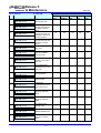
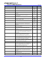
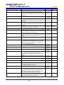
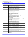
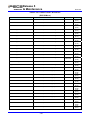
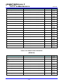
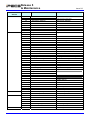
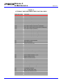
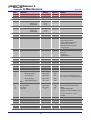
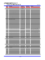
Revision History
Issue
Date
Description of Changes
1.0
1.1
2.0
2.1
2.2
2.3
2.4
2.5
3.0
4.0d2
16-Aug-02
8-Nov-02
29-Aug-03
12-Feb-04
19-Apr-04
18-May-04
28-May-04
29-Jul-04
22-Feb-05
13-Aug-06
Initial release
General editing and update to Software version 1.1Bd
Final update for iPECS Software release 2.
Add Offline Web Admin
Update for iPECS S/W Phase 2
Update for iPECS S/W Phase 2
Update for iPECS S/W Phase 2 (Web Admin)
Update for iPECS S/W Phase 2 (2.0Ai base)
Update for iPECS S/W Phase 3 (3.0As base)
Update for iPECS S/W Phase 4, as of 7-02-06
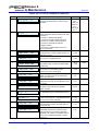
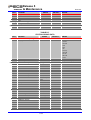
General edits throughout.
Section 1.5 VLAN support added
Added section 1.6 Menu Structure
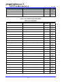
Keyset Admin
PGM 102 btn 8 updated description of Second System address.
PGM 102 btn 16 & 17 added LAN2 port IP address for redundancy.
PGM 103 btn 3 updated for MISC only.
PGM 103 btn 4 and 5 modified for VSF and MCIM, respectively.
PGM 109 btn 10 and 11 added for TNET and Join Conf Room respectively
PGM 111 btn 18 and 19 added for VM Gateway and SIP User ID respectively.
PGM 112 btn 20~24 added for Call Recording and back-up VM station.
PGM 113 btn 18 & 19 added for VMIM/VSF notification to e-mail.
PGM 124 modified for registered station as linked pair.
PGM 132 btn 5 added for TNET.
PGM 141 btn 11 added for IP protocol.
PGM 160 btn 17 added for Conf Room.
PGM 161 btn 18 added for unified message print for serial interface
PGM 161 btn 19 added for message wait and two-way record warning tone.
PGM 161 btn 20 added for CPU redundancy.
PGM 165 btn 29 and 54 added for VMIM/VSF BGM/MOH RTP & RTCP ports.
PGM 171 Added VMIM/VSF Music source
PGM 177 btn 8 & 24 modified for left right deletion.
PGM 179 added for VMIM/VSF Multi-language support.
PGM 190 & 191 added UCS group.
PGMs 330~333 added for TNET and Fail-over.
Web Admin
Added changes as above.
Deleted Menu Tree structure from section 3.4, added section 1.6 see above.
Added section 3.3.3 Java applet for Web password encryption
Station SIP Attributes 2 added for SIP protocol support.
PGM 132 added UMS Sender e-mail address for VM notification to e-mail.
SIP Gateway Attributes added for SIP protocol support.
PGM 177 added SMDR System Domain Name to allow FQDN support for e-mail
delivery.
Zone Data section 3.5.12 added for Zone configurations
Device Login section 3.5.13 added for Remote Registration Table and Password
Login/out.
Station Program section 3.8 expanded.
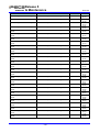
4.0d3
4.0d4
30-Sep-06
01-Dec-06
Update for iPECS S/W Phase 4 (General edits for errata)
Update for iPECS S/W Phase 4 (General edits for errata)
i
IPECS
Release 5
Admin & Maintenance
Issue 5.0
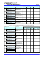
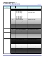
Issue
Date
Description of Changes
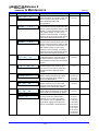
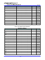
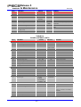
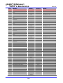
4.0d5
15-Mar-07
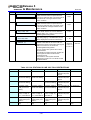
Updated for iPECS S/W Phase 4 (General edits for errata)
Keyset Admin
PGM 174 – Attr 6 Deleted (Purpose : MISC)
PGM 435 – firewall protect default value : from OFF to ON
Web Admin
PGM 106~109 – Updated in case of MFIM600
PGM 174 – Attr 6 Deleted (Purpose : MISC)
PGM 435 – firewall protect default value : from OFF to ON
4.0d6
13-Jun-07
Updated for iPECS S/W Phase 4 (General edits for errata)
Keyset Admin
PGM 100 – Insert warning when change country code
PGM 113 – insert a field (“BY PASS DTMF”)
Web Admin
PGM 113 – insert a field (“BY PASS DTMF”)
ii
IPECS
Release 5
Admin & Maintenance
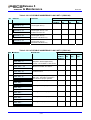
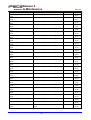
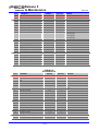
Issue
Date
Description of Changes
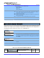
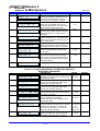
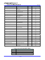
07-Jan-08
Updated for iPECS S/W Phase 5.0
Section 2.3.2.2 partially modified for WTIM Gateway
Section 2.3.5.3 & 2.3.5.5 & 2.3.7.2 & 2.3.9.5 partially modified for expanded VSF
announcement, was 20 now 70
Section 2.3.18 DECT ATTRIBUTES added
Section 3.5.15 DECT Data added
Keyset Admin
PGM102 btn 18 added for DNS IP address
PGM103 btn 7 added for WTIM Gateway
PGM109 btn 12,13 added for Enter Into Conf-Group, Station ICR
PGM111 btn 21 added for Serial DSS usage option
PGM111 btn 22 & 23 added for ICM Dial/Ringback Tone
PGM115 Serial DSS button program description is added
PGM129 added for LESS Label Edit
PGM132 Codec Type G.722 added for LIP-80XX Keyset
PGM142 btn 15 & 16 added for PSTN SMS outgoing & received station
PGM142 btn 17 & 18 added for CO line Dial/Ringback Tone
PGM160 btn 24 added for SIP station connection mode
PGM161btn 22 & 23 added for PSTN SMS number & protocol
PGM161 btn 24 added for added menu
PGM169 btn 4 added for weekday display mode
PGM177 btn 26-29 added for SMDR Interface, SMDR ICM, disconnect cause
PGM178 btn 3 & 4 & 5 added for DST(Daylight Saving Time) ability
PGM195 added for NTP Attributes
PGM231 destination type 12 added for Voice Mail box
PGM231 destination type 13 added for ICLID Routing table
PGM231 flex button 7 added for auto ring assign table
PGM325 added for Network feature code table
PGM444 added for Zone Holiday Assignment
Web Admin
PGM102 insert a filed(“DNS IP Address”)
PGM109 btn 12,13 added for Enter Into Conf-Group, Station ICR
PGM111 btn 21 added for Serial DSS usage
PGM111 btn 22 & 23 added for ICM Dial/Ringback Tone
PGM115 Serial DSS button program and LSS Label edit description inserted
PGM132 Codec Type G.722 added
PGM142 btn 17 & 18 added for CO line Dial/Ringback Tone
PGM161 btn 24 added for added menu
PGM169 btn 4 added for weekday display mode
PGM177 btn 26-29 added for SMDR Interface, SMDR ICM, disconnect cause
PGM195 added for NTP Attributes
PGM196 added for SNMP Attributes
PGM197 added for Cabinet Attributes
PGM231 insert a field(“Auto Ring Mode Table”)
PGM231 insert a destination type
PGM325 added for Network feature code table
PGM439 insert a field(“Display Time Zone”)
PGM444 added for Zone Holiday Assignment
Web Admin – Station Program
Section 3.8.3 added for Station ICR Scenario
Section 3.8.9 added for Conference Group
Update VSF memory/channel capacity
Update and add new attributes for SIP G/W Module Programming Option
Section 3.5.3.4 SIP Gateway Module
Update capacity table for iPECS-1200.
5.0
5.0d1
Issue 5.0
iii
IPECS
Release 5
Admin & Maintenance
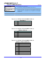
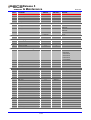
Issue
Date
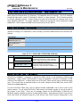
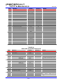
5.0d2
5.0d3
17-Feb-09
17-Feb-09
5.0d4
5.0d5
5.0d6
5.0d7
01-Apr-09
16-Apr-09
09-May-09
15-May-09
5.0d8
12-Jun-09
5.0d9
17-Aug-09
Issue 5.0
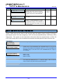
Description of Changes
Add group name for Terminal/Circular/VM/UCS.
Add instruction to expand BRI channel of iPECS-50B in section 1.4.2.
Change MFIM replacement procedure in the section 1.4.2.
Add device type field in the PGM 235(Register table).
Add a field(ISDN REDIRECTING NUMBER) in the PGM 143.
th
Add a field(4 ~9th) in the PGM 161.
Add Unused line type in the PGM 140
Add Reject Anonymous in the PGM 142 Flex19.
Add SMS protocols in the PGM 161 Flex23.
Add Long time call monitoring in the PGM 177 Flex6.
Add Net Num Plan Bin in the PGM 222 Flex7.
Rearrange Destination type index and wording in the PGM 231.
Add error, busy, no answer destination in the PGM 228 Flex 11 ~ Flex13
Add Outgoing mail box destination in the PGM 114 Flex19
Add PPP IP address in the PGM 205 Flex6 ~ Flex7
Web Admin
Add PGM 101 – Device Port Num Change
Add PGM 451, 20th and 21th.
20th(Print out strings those are used to display flexible button)
21th (Print out strings those are used to activate feature)
Web Admin
Add iPECS – Micro content
iv
IPECS
Release 5
Admin & Maintenance
Issue 5.0
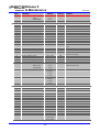
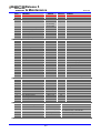
Table Of Contents
1. Introduction...................................................................................... 1-1
1.1
Manual Application................................................................................... 1-1
1.2
General .................................................................................................... 1-2
1.3
Initialization.............................................................................................. 1-3
1.4
Registration.............................................................................................. 1-3
1.4.1 Normal Registration Process ............................................................................... 1-3
1.4.2 Replacement Module Registration ....................................................................... 1-4
1.5
Virtual LANs ............................................................................................ 1-5
1.6
Program Menu Structure ......................................................................... 1-5
2. Station Admin Programming ............................................................ 2-1
2.1
General .................................................................................................... 2-1
2.1.1 LCD & Button Functions ...................................................................................... 2-1
2.1.2 Alphanumeric Data Entries .................................................................................. 2-1
2.1.3 Required Data Entries .......................................................................................... 2-2
2.2
Data Entry Mode...................................................................................... 2-2
2.3
PROCEDURES FOR DATA ENTRY .......................................................... 2-2
2.3.1 SYSTEM ID – PGM CODE 100- .......................................................................... 2-2
2.3.2 NUMBERING PLANS DATA – PGM CODES 102 to 109- ................................. 2-4
2.3.2.1
2.3.2.2
2.3.2.3
2.3.2.4
2.3.2.5
System IP Address Plan -PGM Code 102- ........................................................................2-4
Device IP Address Plan -PGM Code 103- .........................................................................2-6
CO Gateway Sequence Number -PGM Code 104- .........................................................2-10
Flexible Station Numbering Plan -PGM Code 105-..........................................................2-11
Flexible Numbering Plan part A to D -PGM Codes 106 to 109-.......................................2-12
2.3.3 STATION DATA – PGM CODES 110-125- ..................................................... 2-17
2.3.3.1
2.3.3.2
2.3.3.3
2.3.3.4
2.3.3.5
2.3.3.6
2.3.3.7
2.3.3.8
2.3.3.9
2.3.3.10
2.3.3.11
2.3.3.12
2.3.3.13
2.3.3.14
Station Type -PGM Code 110- .........................................................................................2-17
Station Attributes – I to III -PGM Codes 111-113-............................................................2-20
Station Attributes IV -PGM Code 114- .............................................................................2-26
Flexible button Assignment -PGM Code 115- ..................................................................2-28
Station Class-of-Service -PGM Code 116-.......................................................................2-32
CO/IP Group Access -PGM Code 117-............................................................................2-34
Internal Page Zone Access -PGM Code 118- ..................................................................2-34
PTT (Push-To-Talk) Group Access -PGM Code 119-......................................................2-35
Preset Call Forward -PGM Code 120- .............................................................................2-35
Idle Line Selection -PGM Code 121-................................................................................2-36
Station IP Attributes -PGM Code 122- .............................................................................2-37
Station Timers -PGM Code 123- ......................................................................................2-37
Linked Station Table -PGM Code 124- ............................................................................2-38
ICM Tenancy Group -PGM Code 125-.............................................................................2-40
v
IPECS
Release 5
Admin & Maintenance
2.3.3.15
Issue 5.0
LSS Label Edit -PGM Code 129- .....................................................................................2-41
2.3.4 BOARD (GATEWAY) DATA – PGM CODES 130 to 132 -............................... 2-41
2.3.4.1
2.3.4.2
2.3.4.3
H323 VoIP Attributes -PGM CODE 130-..........................................................................2-41
T1/E1/PRI Attributes -PGM CODE 131-...........................................................................2-43
Board Base Attributes -PGM CODE 132- ........................................................................2-43
2.3.5 CO LINE DATA – PGM CODES 140 to 151 -................................................... 2-45
2.3.5.1
2.3.5.2
2.3.5.3
2.3.5.4
2.3.5.5
2.3.5.6
2.3.5.7
2.3.5.8
2.3.5.9
2.3.5.10
CO Service Type -PGM Code 140-..................................................................................2-45
CO/IP Attributes I ~ III -PGM Codes 141~143- ................................................................2-45
CO/IP Ring Assignment -PGM Codes 144- .....................................................................2-51
DID Service Attributes -PGM Code 145-..........................................................................2-52
DISA Service Attributes -PGM Code 146-........................................................................2-53
CO Line Preset Forward Attributes -PGM Code 147- ......................................................2-54
NA ISDN Line Attributes -PGM Code 150-.......................................................................2-55
ISDN CO Line Attributes -PGM Code 151- ......................................................................2-56
T1 Line Timers -PGM Code 152- .....................................................................................2-58
DCOB CO Attribute -PGM Code 153- ..............................................................................2-59
2.3.6 SYSTEM DATA – PGM CODES 160 to 182 - .................................................. 2-60
2.3.6.1
2.3.6.2
2.3.6.3
2.3.6.4
2.3.6.5
2.3.6.6
2.3.6.7
2.3.6.8
2.3.6.9
2.3.6.10
2.3.6.11
2.3.6.12
2.3.6.13
2.3.6.14
2.3.6.15
2.3.6.16
2.3.6.17
2.3.6.18
2.3.6.19
2.3.6.20
2.3.6.21
2.3.6.22
2.3.6.23
System Attributes I & II -PGM Codes 160 to 161-............................................................2-60
System Password -PGM Code 162- ................................................................................2-64
Alarm Attributes -PGM Code 163-....................................................................................2-65
Attendant Assignment -PGM Code 164- ..........................................................................2-66
Multi-cast RTP/RTCP Ports -PGM Code 165- .................................................................2-66
DISA COS -PGM Code 166- ............................................................................................2-75
DID/DISA Destination -PGM Code 167-...........................................................................2-75
External Control Contacts -PGM Code 168- ....................................................................2-76
LCD Display Mode -PGM Code 169- ...............................................................................2-77
Button LED Flash Rate -PGM Code 170- ........................................................................2-78
Music Sources -PGM Code 171-......................................................................................2-80
PBX Access Codes -PGM Code 172- ..............................................................................2-81
Ringing Line Preference Priority -PGM Code 173- ..........................................................2-81
RS-232 Port Settings -PGM Code 174- ...........................................................................2-82
Serial Port Function Selections -PGM Code 175- ............................................................2-83
Break/Make Ratio -PGM Code 176-.................................................................................2-85
SMDR Attributes -PGM Code 177- ..................................................................................2-85
System Date, Time and Daylight Saving Time (DST) -PGM Code 178-..........................2-88
Multi Language –PGM Code 179-....................................................................................2-89
System Timers I to III -PGM Codes 180-182- ..................................................................2-89
In-Room Indication -PGM Code 183- ...............................................................................2-92
DCOB SYS Timers -PGM Code 186-...............................................................................2-93
NTP Attributes -PGM Code 195-......................................................................................2-94
2.3.7 STATION GROUP DATA – PGM CODES 190 & 192-..................................... 2-94
2.3.7.1
2.3.7.2
2.3.7.3
Station Group Assignment -PGM Code 190- ...................................................................2-95
Station Group Attributes -PGM Code 191-.......................................................................2-96
Pick Up Group Assignment -PGM Code 192- ................................................................2-107
2.3.8 ISDN LINE & ICLID ROUTING DATA – PGM CODES 200-205- ................. 2-108
2.3.8.1
2.3.8.2
2.3.8.3
2.3.8.4
2.3.8.5
2.3.8.6
ISDN Attributes -PGM Code 200- ..................................................................................2-108
CLIP/COLP Table -PGM Code 201- ..............................................................................2-108
MSN Table -PGM Code 202- .........................................................................................2-109
ICLID Route Table -PGM Code 203- .............................................................................2-110
ICLID Ring Assignment -PGM Code 204-......................................................................2-111
ISDN PPP Web Admin Attributes -PGM Code 205- ......................................................2-112
2.3.9 TABLES DATA – PGM CODES 220 to 235 -................................................. 2-113
2.3.9.1
2.3.9.2
2.3.9.3
LCR Assignment Tables -PGM Codes 220 to 223- .......................................................2-113
Toll Tables -PGM Code 224-..........................................................................................2-118
Emergency Code Table -PGM Code 226- .....................................................................2-119
vi
IPECS
Release 5
Admin & Maintenance
2.3.9.4
2.3.9.5
2.3.9.6
2.3.9.7
2.3.9.8
2.3.9.9
2.3.9.10
2.3.9.11
2.3.9.12
2.3.9.13
Issue 5.0
Authorization Codes Table -PGM Code 227-.................................................................2-119
Customer Call Routing/VSF AA Table -PGM Code 228- ...............................................2-120
Executive/Secretary Table -PGM Code 229- .................................................................2-121
Flexible DID Conversion Table -PGM Code 231- ..........................................................2-122
System Speed Zone Table -PGM Code 232-.................................................................2-124
Auto Ring Mode -PGM Code 233- .................................................................................2-125
Voice Mail Dialing Table -PGM Code 234-.....................................................................2-126
Registration & Fractional Module Table –PGM Code 235- ............................................2-127
Mobile Extension Table –PGM Code 236- .....................................................................2-128
Hot Desk Attributes –PGM Code 250- ...........................................................................2-129
2.3.10 NETWORKING DATA – PGM CODES 320 to 324-........................................ 2-130
2.3.10.1
2.3.10.2
2.3.10.3
2.3.10.4
2.3.10.5
Network Basic Attribute -PGM Code 320-......................................................................2-130
Network Supplementary Attribute -PGM Code 321- ......................................................2-131
Network CO LINE Attribute -PGM Code 322- ................................................................2-132
NET Numbering Plan Table -PGM Code 324- ...............................................................2-132
Network Feature Code Table -PGM Code 325- .............................................................2-134
2.3.11 TNET (Centralized Networking) – PGM CODES 330 – 336- ...................... 2-134
2.3.11.1
2.3.11.2
2.3.11.3
2.3.11.4
2.3.11.5
2.3.11.6
2.3.11.7
TNET Basic Attributes – PGM Code 330 .......................................................................2-134
TNET CM Attributes – PGM Code 331 ..........................................................................2-135
TNET LM ATTRIBUTES – PGM Code 332....................................................................2-136
FoPSTN Attributes – PGM Code 333.............................................................................2-137
TNET LM External Contact Attributes – PGM Code 334 ...............................................2-138
TNET LM Music Attributes – PGM Code 335.................................................................2-138
TNET LM Alarm Attributes – PGM Code 336.................................................................2-139
2.3.12 RSGM & Remote Device Data – PGM CODES 430-435- .............................. 2-140
2.3.12.1
2.3.12.2
2.3.12.3
2.3.12.4
2.3.12.5
2.3.12.6
RSGM & Remote Device Table -PGM Code 430- .........................................................2-140
RSGM Multi-Cast RTP/RTCP Ports -PGM Code 431-...................................................2-141
RSGM External Control Contact -PGM Code 432- ........................................................2-142
RSGM Alarm Attribute -PGM Code 433-........................................................................2-142
RSGM Music Assignment -PGM Code 434- ..................................................................2-143
RSGM Service Attributes -PGM Code 435- ...................................................................2-144
2.3.13 Zone Data – PGM CODES 436-441, 444 ........................................................ 2-145
2.3.13.1
Zone Holiday Assignment -PGM Code 444- ..................................................................2-145
2.3.14 INITIALIZATION -PGM Code 450- ................................................................ 2-146
2.3.15 PRINT-OUT DATABASE -PGM Code 451- .................................................. 2-147
2.3.16 VIRTUAL TRACE DIP-SWITCH -PGM Code 452- ....................................... 2-148
2.3.17 VIRTUAL DIP-SWITCH -PGM Code 453-..................................................... 2-149
2.3.18 DECT ATTRIBUTES-PGM Code 491 ............................................................. 2-150
3. WEB SERVICE ................................................................................. 3-1
3.1
General .................................................................................................... 3-1
3.1.1 PC/Browser .......................................................................................................... 3-1
3.1.2 Environment for LAN connection ........................................................................ 3-1
3.1.3 Web Browser setting............................................................................................ 3-1
3.2
3.2.1
3.2.2
3.2.3
3.2.4
Web Home Page....................................................................................... 3-3
Browser Access ................................................................................................... 3-3
User's Guide ......................................................................................................... 3-4
Station Program.................................................................................................... 3-5
Web Admin & Maintenance.................................................................................. 3-5
vii
IPECS
Release 5
Admin & Maintenance
3.3
Issue 5.0
WEB ADMIN Data Modification & Access ............................................... 3-6
3.3.1 Web Admin Data Modification ............................................................................. 3-6
3.3.2 Maintenance & Admin Password......................................................................... 3-6
3.3.3 Password Encryption ........................................................................................... 3-7
3.4
WEB ADMIN & MAINTENANCE OVERVIEW .......................................... 3-8
3.5
iPECS WEB ADMINISTRATION............................................................... 3-9
3.5.1 System ID & Numbering Plans .......................................................................... 3-10
3.5.1.1
3.5.1.2
3.5.1.3
3.5.1.4
3.5.1.5
3.5.1.6
System ID .........................................................................................................................3-11
Device Port Num Change.................................................................................................3-12
System & Device IP Address Plan ...................................................................................3-15
CO Gateway Sequence Number......................................................................................3-18
Flexible Station Numbering Plan ......................................................................................3-20
Flexible Numbering Plan ..................................................................................................3-21
3.5.2 Station Data Program ......................................................................................... 3-25
3.5.2.1
3.5.2.2
3.5.2.3
3.5.2.4
3.5.2.5
3.5.2.6
3.5.2.7
3.5.2.8
3.5.2.9
3.5.2.10
3.5.2.11
3.5.2.12
3.5.2.13
3.5.2.14
3.5.2.15
3.5.2.16
3.5.2.17
Station Type .....................................................................................................................3-26
Station Attributes ..............................................................................................................3-27
Station ISDN Attributes.....................................................................................................3-32
Flexible Buttons ................................................................................................................3-34
Station COS......................................................................................................................3-35
CO/IP Group Access ........................................................................................................3-37
Internal Page Zone Access ..............................................................................................3-38
PTT Group Access ...........................................................................................................3-39
Preset Call Forward..........................................................................................................3-40
Idle Line Selection ............................................................................................................3-41
Station IP Attributes..........................................................................................................3-42
Station Timers ..................................................................................................................3-43
Linked Station...................................................................................................................3-44
Station ICM Tenancy Group .............................................................................................3-46
Station SIP Attributes 2 ....................................................................................................3-47
Station Name Display .......................................................................................................3-49
Station Copy .....................................................................................................................3-50
3.5.3 Board (gateway Module) Data ........................................................................... 3-51
3.5.3.1
3.5.3.2
3.5.3.3
3.5.3.4
H323 VoIP Attributes ........................................................................................................3-52
T1/PRI Attributes ..............................................................................................................3-54
Board Base Attributes.......................................................................................................3-55
SIP Gateway Attributes ....................................................................................................3-57
3.5.4 CO Line Data....................................................................................................... 3-61
3.5.4.1
3.5.4.2
3.5.4.3
3.5.4.4
3.5.4.5
3.5.4.6
3.5.4.7
3.5.4.8
3.5.4.9
CO/IP Attributes................................................................................................................3-62
CO Ring Assignment ........................................................................................................3-66
DID Service Attributes ......................................................................................................3-67
DISA Service Attributes ....................................................................................................3-69
CO/IP Preset Forward Attributes......................................................................................3-70
NA ISDN Line Attributes ...................................................................................................3-71
ISDN CO Line Attributes...................................................................................................3-73
T1 CO Line Attributes .......................................................................................................3-77
DCOB CO Line Attributes.................................................................................................3-79
3.5.5 System Data........................................................................................................ 3-80
3.5.5.1
3.5.5.2
3.5.5.3
3.5.5.4
3.5.5.5
System Attributes .............................................................................................................3-81
System Password.............................................................................................................3-85
Alarm Attributes ................................................................................................................3-86
Attendant Assignment ......................................................................................................3-87
Multi-cast RTP/RTCP .......................................................................................................3-88
viii
IPECS
Release 5
Admin & Maintenance
3.5.5.6
3.5.5.7
3.5.5.8
3.5.5.9
3.5.5.10
3.5.5.11
3.5.5.12
3.5.5.13
3.5.5.14
3.5.5.15
3.5.5.16
3.5.5.17
3.5.5.18
3.5.5.19
3.5.5.20
3.5.5.21
3.5.5.22
3.5.5.23
3.5.5.24
3.5.5.25
3.5.5.26
3.5.5.27
3.5.5.28
3.5.5.29
Issue 5.0
DISA COS.........................................................................................................................3-96
DID/DISA Destination .......................................................................................................3-97
External Control Contacts.................................................................................................3-98
LCD Display Mode............................................................................................................3-99
LED Flashing Rate .........................................................................................................3-101
Music Sources ................................................................................................................3-104
PBX Access Codes ........................................................................................................3-105
Ringing Line Preference Priority.....................................................................................3-106
RS-232 Port Settings......................................................................................................3-107
Serial Port Function Selections ......................................................................................3-109
Break/Make Ratio ...........................................................................................................3-110
SMDR Attributes.............................................................................................................3-111
System Date & Time.......................................................................................................3-114
System Multi Language ..................................................................................................3-116
System Timers................................................................................................................3-117
In-Room Indication .........................................................................................................3-121
Web Access Authorization..............................................................................................3-122
Hot Desk Attributes.........................................................................................................3-123
System Speed Dial .........................................................................................................3-125
Custom Messages..........................................................................................................3-126
NTP Attributes ................................................................................................................3-127
SNMP Attribute...............................................................................................................3-128
Cabinet Attributes ...........................................................................................................3-130
System Call Routing .......................................................................................................3-131
3.5.6 Station Group Data ........................................................................................... 3-133
3.5.6.1
3.5.6.2
3.5.6.3
3.5.6.4
3.5.6.5
Station Group Overview .................................................................................................3-134
Station Group Assignment..............................................................................................3-135
Station Group Attributes .................................................................................................3-137
Pick Up Group Overview ................................................................................................3-151
Pick Up Group Assignment ............................................................................................3-152
3.5.7 ISDN Line & ICLID Routing Data..................................................................... 3-153
3.5.7.1
3.5.7.2
3.5.7.3
3.5.7.4
3.5.7.5
3.5.7.6
ISDN Attributes...............................................................................................................3-154
CLIP/COLP Table...........................................................................................................3-155
MSN Table......................................................................................................................3-156
ICLID Route Table..........................................................................................................3-157
ICLID Ring Assignment Table ........................................................................................3-158
ISDN PPP Web Admin Attributes...................................................................................3-159
3.5.8 Tables Data....................................................................................................... 3-160
3.5.8.1
3.5.8.2
3.5.8.3
3.5.8.4
3.5.8.5
3.5.8.6
3.5.8.7
3.5.8.8
3.5.8.9
3.5.8.10
3.5.8.11
3.5.8.12
3.5.8.13
3.5.8.14
3.5.8.15
LCR Control Attributes....................................................................................................3-161
LCR – LDT (Leading Digit Table) ...................................................................................3-163
LCR – DMT (Digit Modification Table)............................................................................3-165
LCR Table Initialization...................................................................................................3-167
Toll Exception Table .......................................................................................................3-168
Emergency Code Table..................................................................................................3-170
Authorization Code Table ...............................................................................................3-171
Customer Call Routing Table .........................................................................................3-172
Executive/Secretary Table..............................................................................................3-174
Flexible DID Conversion Table.......................................................................................3-175
System Speed Zone Table .............................................................................................3-177
Auto Ring Mode Table....................................................................................................3-178
Voice Mail Dialing Table .................................................................................................3-179
Registration Table & Fractional Module Table ...............................................................3-181
Mobile Extension Table ..................................................................................................3-182
3.5.9 Networking Data............................................................................................... 3-184
3.5.9.1
3.5.9.2
Network Basic Attributes ................................................................................................3-185
Network Supplementary Attributes.................................................................................3-186
ix
IPECS
Release 5
Admin & Maintenance
3.5.9.3
3.5.9.4
3.5.9.5
Issue 5.0
Network CO Line Attributes ............................................................................................3-188
Network Numbering Plan Table .....................................................................................3-189
Network Feature Code Table .........................................................................................3-191
3.5.10 Remote Device Data......................................................................................... 3-192
3.5.10.1
3.5.10.2
3.5.10.3
3.5.10.4
Remote Device Address.................................................................................................3-193
Remote Music Address ..................................................................................................3-194
Remote Ext Contact .......................................................................................................3-195
RSGM Alarm Attributes ..................................................................................................3-196
3.5.11 TNET (Central Control Networking) Data ...................................................... 3-198
3.5.11.1
3.5.11.2
3.5.11.3
3.5.11.4
3.5.11.5
3.5.11.6
Tnet Basic Attributes(PGM 330).....................................................................................3-199
Tnet CM Attributes (PGM 331) .......................................................................................3-200
Tnet LM Attributes (PGM 332)........................................................................................3-202
Tnet FoPSTN table (PGM 333) ......................................................................................3-203
TNET LM EXT CONTACT (PGM 334) ...........................................................................3-204
TNET LM MUSIC/ALARM ATTRIBUTES (PGM 335/336).............................................3-205
3.5.12 Zone Data.......................................................................................................... 3-206
3.5.12.1
3.5.12.2
3.5.12.3
3.5.12.4
3.5.12.5
3.5.12.6
3.5.12.7
Device Zone Number......................................................................................................3-207
Device Zone Attributes ...................................................................................................3-208
Access & Page Relay .....................................................................................................3-210
Zone Attribute .................................................................................................................3-211
Zone RTP Relay Group ..................................................................................................3-213
Inter Zone Attribute.........................................................................................................3-214
Zone Holiday Assignment...............................................................................................3-216
3.5.13 Device Login..................................................................................................... 3-217
3.5.13.1
3.5.13.2
Remote Phone & CO Gateway Registration ..................................................................3-218
Station User Login ..........................................................................................................3-219
3.5.14 Initialization ...................................................................................................... 3-221
3.5.14.1
Initialization Table...........................................................................................................3-222
3.5.15 DECT Data ........................................................................................................ 3-223
3.5.15.1
3.5.15.2
3.6
3.6.1
3.6.2
3.6.3
3.6.4
3.6.5
3.6.6
FILE UPLOAD & REMOTE UPGRADE................................................. 3-228
File Upload........................................................................................................ 3-229
Upgrade Process .............................................................................................. 3-230
Upgrade Process View..................................................................................... 3-232
VSF Prompt Upgrade View.............................................................................. 3-233
VSF System Greeting Up & Download View .................................................. 3-234
iPECS System Upgrade Process ..................................................................... 3-236
3.6.6.1
3.6.6.2
3.6.6.3
3.6.6.4
3.6.6.5
3.7
DECT Registration..........................................................................................................3-224
DECT ATTRIBUTES ......................................................................................................3-227
iPECS Software Full Upgrade Sequence.......................................................................3-236
MFIM Upgrade................................................................................................................3-239
Upgrade HTML Files ......................................................................................................3-239
Appliances Upgrade (gateway Module and iPECS Phone) ...........................................3-239
Direct Appliances Upgrade.............................................................................................3-239
MAINTENANCE................................................................................... 3-241
3.7.1 Database ........................................................................................................... 3-242
3.7.1.1
3.7.1.2
Database Download .......................................................................................................3-243
Database Upload............................................................................................................3-245
3.7.2 SMDR ................................................................................................................ 3-246
3.8
STATION PROGRAM (User Portal) ..................................................... 3-247
3.8.1 Station Attributes ............................................................................................. 3-248
x
IPECS
Release 5
Admin & Maintenance
Issue 5.0
3.8.2 Call Forward ..................................................................................................... 3-250
3.8.2.1
3.8.2.2
Station Call Forward .......................................................................................................3-250
Preset Call Forward........................................................................................................3-250
3.8.3 Station ICR Scenario ........................................................................................ 3-251
3.8.4 Station Speed Dial ............................................................................................ 3-252
3.8.5 Pre-selected Message ..................................................................................... 3-253
3.8.6 Flex Buttons ..................................................................................................... 3-254
3.8.7 Internal SMS ..................................................................................................... 3-255
3.8.8 External SMS .................................................................................................... 3-256
3.8.9 Station List Management.................................................................................. 3-257
3.8.10 Conference Group ............................................................................................ 3-258
3.8.11 Station Logout .................................................................................................. 3-261
xi
IPECS
Release 5
Admin & Maintenance
Issue 5.0
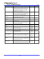
1. INTRODUCTION
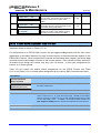
1.1 MANUAL APPLICATION
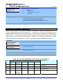
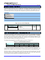
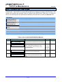
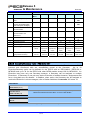
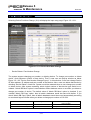
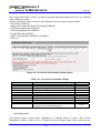
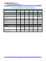
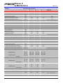
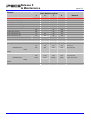
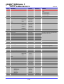
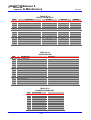
This manual provides detailed information on the database management of the iPECS Series
systems. The iPECS Series is available with several versions of the call server configuration
including the 31 channel iPECS-Micro, the 50 channel iPECS-50, the 100-channel MFIM100, the
300-channel MFIM300, the 600-channel MFIM600 and the 1200-channel MFIM1200. Several
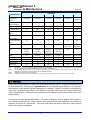
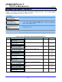
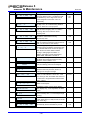
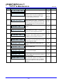
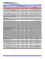
other variations exist between systems based on the model employed as shown in Table 1.1-1
System Capacity Chart.
Table 1.1-1 System Capacity Chart
CAPACITY
DESCRIPTION
Main Cabinet
System Capacity
Stations
*1
PSTN circuits*1
iPECS-Micro
iPECS-50
MFIM100
MFIM300
MFIM600
MFIM1200
n/a
n/a
10 slots
10 slots
10 slots
10 slots
31 ports
50 ports
100 ports
300 ports
600 ports
1200 ports
70
300
600
1200
42
200
400
600
26
50
(Basic: 2 SLT)
(Basic: 2 SLT)
5
max 42, basic
(Basic: 5 VOIP
iPECS 50A
channels)
std 4 PSTN + VoIP
(Basic: 6 VOIP (Basic: 6 VOIP
channels)
channels)
iPECS 50B
std. 4 BRI + VoIP
*2
Max. RSGMs
13
25
35
150
300
600
Attendants
4
4
4
5
5
5
n/a
1
1
1
1
1
USB Host port
1
1
1
1
1
1
Alarm/Door bell
n/a
1
2
2
2
2
n/a
1
2
4
4
4
Music Source Inputs
n/a
1
2
2
2
2
Power Fail Circuit
n/a
1
4
Serial Port (RS232C)
input
External Control
Relays
External Page
4 + Ext. PFTU 4 + Ext. PFTU 4 + Ext. PFTU
(6 optional)
(6 optional)
(6 optional)
n/a
1
2
2
2
2
Internal Page Zones
10
10
10
35
35
100
System Speed Dial
800 (48 digits)
800 (48 digits)
zones
800 (48 digits) 3000 (48 digits) 6000 (48 digits)
12000
(48 digits)
System Speed Dial
10
10
10
10
20
50
Station Speed Dial
20 (48 digits)
20 (48 digits)
20 (48 digits)
100 (48 digits) 100 (48 digits) 100 (48 digits)
Last Number Redial
10 (48 digits)
10 (48 digits)
10 (48 digits)
10 (48 digits)
Zones (Groups)
1-1
10 (48 digits) 10 (48 digits)
IPECS
Release 5
Admin & Maintenance
Issue 5.0
CAPACITY
DESCRIPTION
iPECS-Micro
iPECS-50
MFIM100
MFIM300
MFIM600
1 (48 digits)
1 (48 digits)
1 (48 digits)
1 (48 digits)
1 (48 digits)
1
3
3
9
9
9
5000
5000
5000
10000
15000
30000
CO Line Groups
20
20
20
72
72
200
Station & Hunt
12
40
40
48
48
100
26
50
70
70
70
200
10
10
10
36
36
160
500(26/474)
500(50/450)
500(70/430)
1000(300/700)
2000
4000
(600/1400)
(1200/2800)
210(175)
280(245)
210(175)
210(175)
n/a
n/a
Save Number
Redial
DSS
MFIM1200
1 (48 digits)
Consoles/Station
SMDR buffer
Groups
Station & Hunt
Group Members
Executive/Secretary
pairs
Authorization Codes
VSF*3
minutes
minutes
minutes
minutes
(4 channels)
(6 channels)
(6 channels)
(6 channels)
VMIM
n/a
9 hours
9 hours
9 hours
9 hours x 6
9 hours x 30
MCIM
1
2
2
4
8
8
16
16
16
32
32
32
5
4/8
6
6
n/a
n/a
No
No
Yes
Yes
Yes
Yes
WTIM
*4
VoIP channels
Redundancy
Note 1
Note 2
Note 3
Note 4
The station and CO Line maximums are not simultaneously; total ports cannot exceed 100 with MFIM100, 50 with IPECS-50,
300 with MFIM300 and 600 with the MFIM600 and 1200 with the MFIM1200.
For maximum RSGM connection ports, calculation formula is ports = available system station ports)/2, there must be
sufficient VoIP channels to support packet relay for RSGM rtp packets.
16 M byte is used for prompt (35 minutes)
iPECS-50 can support 8 VoIP channels if G.711 is used or4 channels if complex codec (G.723.1/G.729) is used
1.2 GENERAL
iPECS can be programmed to meet each customer's individual needs. System programming may
be accomplished by entering the “PROGRAM MODE” at an assigned Admin Station or by pointing a
Web Browser at the system’s MFIM private/public IP address. Section 2 provides a description for
data entry using the Admin Station, and Section 3 provides instructions for entering data when
using a Web Browser. Note that some parameters are available through Web Admin and not the
Keyset Admin.
This section provides general information. An index to database entries, default value charts for
the Flexible Numbering Plan, Fixed Function dial-codes and the entire database are provided in
Appendix A through D, respectively. The index and charts are helpful references when entering
data into the system’s database.
1-2
IPECS
Release 5
Admin & Maintenance
Issue 5.0
1.3 INITIALIZATION
When power is applied to the MFIM or the MFIM Reset button is pressed, the system will initiate
the “Power-up” routine. During the Power-Up routine the system will check the Initialization switch
(4th position of the MFIM DIP-switch), refer to the iPECS Description and Installation Manual
section 4.4.2. If the switch is in the OFF position, the system will perform a simple Power-Up
routine; clear all scratch-pad memory, load run-time programs, establish communications with
each registered gateway Module and iPECS terminal, send RESTART commands and load
appropriate settings to the Modules and terminals. If a Module or terminal does not respond after
several attempts, the system places the device in an out-of-service mode but maintains the
database settings. Once the Power-up routine is complete, the system will conduct normal
operations.
If the Initialization switch is in the ON position, in place of the Power-Up routine, the system will
perform the full Initialization procedure. The initialization procedure will set the system database to
default values, refer to Appendix D. Further, during the full initialization procedure, the system will
establish communications with each gateway Module and iPECS terminal for registration. This
communication will use the default device IP address and using the MFIM MAC address for
system identification. The system will assign IP addresses and Sequence Numbers for each
gateway Module and iPECS terminal and use these values for subsequent communication and
logical assignments of numbering plans, respectively. In addition, the system sends commands to
modify all settings to the default values, including IP addresses but maintains the existing
Sequence Numbers. After successfully registering, should a device not respond to several
attempts by the system, the system places the device in an out-of-service mode but maintains the
database. Once initialization is complete, set the initialization switch to the OFF position to protect
the database. The system must be restarted to complete the initialization.
1.4 REGISTRATION
1.4.1
Normal Registration Process
Module & Terminal
When power is applied and an Ethernet link is established, an unregistered device will attempt to
discover and register with a local (on the same LAN) iPECS system. The Module or terminal will
send a registration request to the assigned iPECS system (MFIM) IP address. If no response is
received, the device will generate a Multi-cast discovery request for registration.
Remote iPECS Phone & Remote Services Module
A remote device, iPECS Phone or gateway Module, registers with the system using the MAC
address of the device. The MAC address must be assigned in the system database and the IP
address of the system must be assigned in the remote device. Using this address, the remote
device will attempt to register with the assigned iPECS system. When the system receives the
registration request, the MAC address is compared with the database to authenticate the remote
device. With a matching MAC, the system will accept the registration request and provide the
remote device with the appropriate settings. Note that the position of the MFIM Registration switch
does not affect remote registration.
1-3
IPECS
Release 5
Admin & Maintenance
Issue 5.0
iPECS system
When power is applied, an Ethernet link is established, and the Registration switch (MFIM DIPswitch position 3) is in the ON position, the MFIM will send a Multi-cast request to unregistered
gateway Modules and iPECS terminals for registration.
When the system receives a valid registration or discovery request, and the Registration switch
(MFIM DIP-switch position 3) is in the ON position, the system will respond to the gateway Module
or terminal with a Registration command including the system IP and MAC address. During the
registration process, the Module or terminal will receive data from the system including a
Sequence Number, IP address, RTP characteristics, etc, as well as default settings appropriate to
the type of Module or terminal. Once registered, the Module or terminal will maintain the system IP
and MAC address in non-volatile memory and will not attempt further registrations.
If the Registration switch is in the OFF position, the system will not respond to normal registration
requests from a local device.
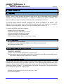
1.4.2 Replacement Module Registration
Under certain situations, it is necessary to force the registration of gateway modules and terminals
specifically when an MFIM, gateway Module or iPECS Terminal is replaced. When replacing an
MFIM, gateway Modules and iPECS terminals must be forced to register with the new system.
With Module or terminal replacement, the system must recognize the “replacement” status to
transfer the existing database values.
When replacing an MFIM, after following the instructions of section 4.4.2 in the iPECS Description
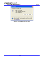
& Installation Manual, the local Web interface is used to access the system. The user may update
the system database using the database downloaded from the previous MFIM memory.
Using the Terminal mode Command Line interface(“maint>reset ip”), the user provides the new
MFIM with the IP address of the previous MFIM, and issues the Register command. The new
system will then send a Uni-cast Register command to each gateway Module and iPECS terminal
registered to the previous system. This Register command will include the previous system IP
address. These commands are repeated several times only. As communication is established,
the new MFIM will update the settings of the gateway Modules and iPECS terminals appropriately.
When the gateway Modules and terminals respond, they are registered to the new system.
When replacing a gateway Module, use PROGRAM CODES 103 and 104 (in Web Admin “System &
Device IP Address Plan” and “CO Gateway Sequence Number”) to delete the existing MAC
information and assign the MAC information for the new module. Install the new gateway Module.
When replacing an iPECS terminal, using PROGRAM CODES 103 and 105 (Web Admin “System &
Device IP Address” and “Flexible Station Numbering Plan”), delete the MAC information for the
previous iPECS terminal and assign the MAC information for the new iPECS terminal. Install the
new terminal.
The Basic iPECS-50B has 2 x ISDN2 circuits (4 Channels) this can be increased to 4 x ISDN2
1-4
IPECS
Release 5
Admin & Maintenance
Issue 5.0
circuits (8 Channels) by the installation of a License (BRIU Lock Key). If the Lock Key is installed
when the system is initialized it will have 8 channels available.
If the Lock key is installed to increase the number of channels at some time after installation, the
BRI gateway will have to be deleted in the maintenance menu and then Re-Registered with “MAX
Port 8” using the Registration Table (PGM235).
1.5 VIRTUAL LANS
iPECS devices (modules and terminals) support the IEEE 802.1p/Q standard for Virtual LAN
operation. The VLAN priority and ID (tag) are assigned in the Web Admin of each module and
terminal. For the MFIM, assign VLAN parameters in maintenance through the RS-232 port or a
TCP/IP connection with the following commands:
maint> vlanset pri [value]
// priority from 0 to 7
maint> vlanset id [value]
// vlan id value (0 to 4094)
maint> vlan start
// start.
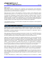
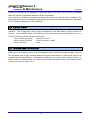
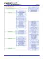
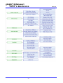
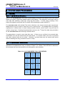
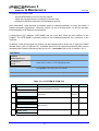
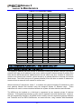
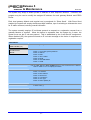
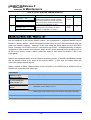
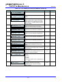
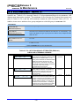
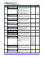
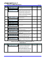
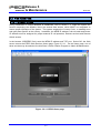
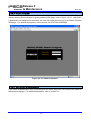
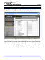
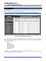
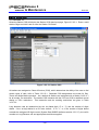
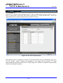
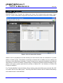
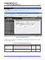
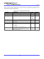
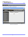
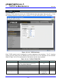
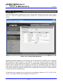
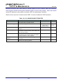
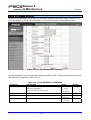
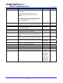
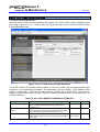
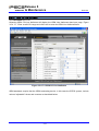
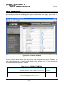
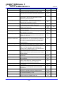
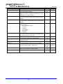
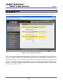
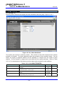
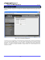
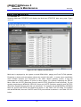
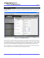
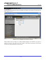
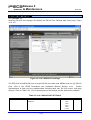
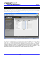
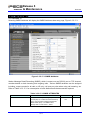
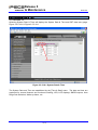
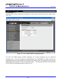
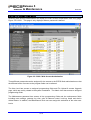
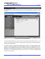
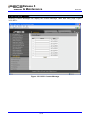
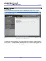
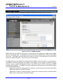
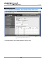
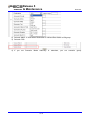
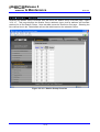
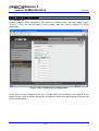
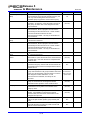
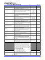
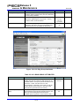
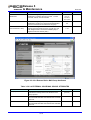
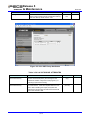
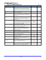
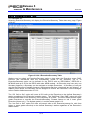
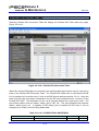
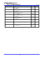
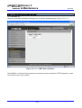
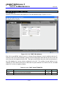
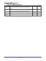
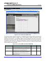
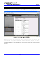
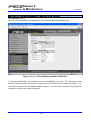
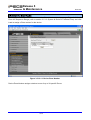
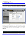
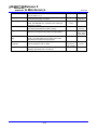
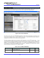
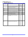
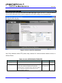
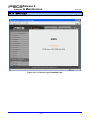
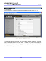
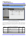
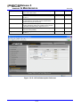
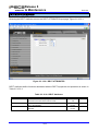
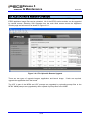
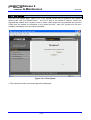
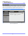
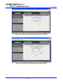
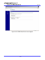
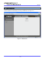
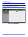
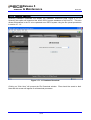
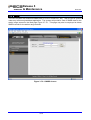
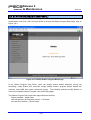
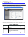
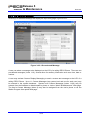
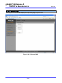
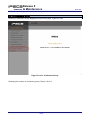
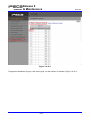
1.6 PROGRAM MENU STRUCTURE
Database Administration is accomplished by entering “PROGRAM CODES” from the dial pad of an
iPECS phone or selecting an item from the Navigation pane in iPECS Web Admin pages. Items in
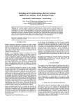
the Navigation pane roughly correlate with the Program codes however; certain items can only be
assigned via the Web interface. Data items are organized as a group with a common affect, i.e.
station, system, numbering plan, etc. Items may be further grouped forming a multi-layered menu
structure as shown in Figure 1.6-1.
1-5
IPECS
Release 5
Admin & Maintenance
1-6
Issue 5.0
IPECS
Release 5
Admin & Maintenance
1-7
Issue 5.0
IPECS
Release 5
Admin & Maintenance
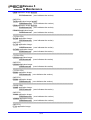
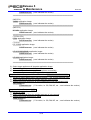
Figure 1.6-1 Admin Menu Structure
1-8
Issue 5.0
IPECS
Release 5
Admin & Maintenance
Issue 5.0
2. STATION ADMIN PROGRAMMING
2.1 GENERAL
2.1.1 LCD & Button Functions
While in the PROGRAM MODE, the Liquid Crystal Display (LCD) and Flex button LEDs of an Admin
Station are used to guide and indicate status of the feature. The dial-pad is most often used to
enter data after selecting a data item using the Flex buttons. In some cases, pressing a Flex
button will toggle the entry with the Flex button LED indicating the status (ON/OFF).
For PROGRAM CODES with multiple Flex button selections, the volume controls ([VOL UP] and [VOL
DOWN] buttons) may be used to select the next or previous item. The [SPEED] button is generally
employed as a delete button to erase existing entries however, where noted, it may be used to
confirm a range input. Pressing the [CONF] button returns to the 1st step of the data entry procedure
for the PROGRAM CODE without storing unsaved entries.
The [SAVE] button is used to store data after entry. If there are no conflicts in the entered data,
confirmation tone will be received and the data stored. If a conflict exists, error tone is provided
and newly entered data are not saved. Generally, corrected data may be entered and stored
without restarting the entry procedure from the 1st step.
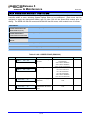
2.1.2 Alphanumeric Data Entries
In some cases, an alphanumeric entry is required. Two (2) dial-pad digits represent each
character of an alphanumeric entry, as shown in Table 2.1.2-1 below. Use the Table to determine
the two digits that must be entered from the dial-pad for each character.
Table 2.1.2-1 ALPHANUMERIC DIAL-PAD ENTRIES
Q – 11
A - 21
D - 31
Z – 12
B - 22
E - 32
. – 13
C - 23
F - 33
1 – 10
2 - 20
3 - 30
G – 41
J - 51
M - 61
H - 42
K - 52
N - 62
I - 43
L - 53
O - 63
4 - 40
5 - 50
6 - 60
P - 71
T - 81
R - 72
U - 82
S - 73
V - 83
Q - 7*
8 - 80
7 - 70
W - 91
X - 92
Y - 93
Z - 9#
9 - 90
Blank - *1
: - *2
0-00
, - *3
2-1
#
IPECS
Release 5
Admin & Maintenance
Issue 5.0
2.1.3 Required Data Entries
During initialization a default database is established, refer to section 1.3 and Appendix A~D.
However, there are several data entries, which MUST be completed to assure proper operation of
the system. The system employs the Country Code, refer to section 2.3.1, to establish tone and
gain plans specific to the country. Also, the MFIM IP address, sub-net mask and Default Gateway
(Router) IP address, refer to section 2.3.2.1, must be assigned for proper external IP call operation
and WAN access as well as remote Web Admin access.
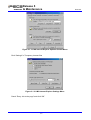
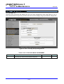
2.2 DATA ENTRY MODE
All data entry is accomplished from an Admin Station or station assigned for data entry (Station
Attributes III PGM CODE 113, Flex button 1). After initialization and registration, any iPECS Phone
may access the system database. In addition, as default, there is no Station Admin password
defined. To enter the PROGRAM MODE, from the Admin Station follow the procedure below. In the
left column of the chart are the LCD displays and in the right column are step-by-step instructions
to modify database items.
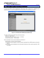
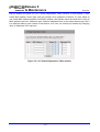
PROCEDURE:
STATION 100 (T)
04 SEP 01
02:49 PM
ENTER ADMIN PASSWORD
Press the [PGM] button.
Dial ‘*’ and ‘#’.
Enter the Admin password. Confirmation tone is received.
ADMIN PROGRAM START
ENTER PGM NUMBER
To select a program, use the instructions in the following sections, starting with
“Press the [PGM] button” and dial the specified Admin PROGRAM CODE.
2.3 PROCEDURES FOR DATA ENTRY
The following sections provide specific instructions for entering data from the Admin Station once
in the PROGRAM MODE. Each section provides descriptive information, step-by-step instructions
and Tables for determining appropriate entries.
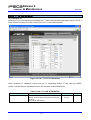
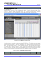
2.3.1 SYSTEM ID – PGM CODE 100Under System ID, the country is identified using the international dial codes (COUNTRY CODE). If
the Country code requires changing, the system must be initialized to restructure memory and
create the country specific defaults, gain, frequencies and other system characteristics specific to
the country and regional regulatory requirements.
2-2
IPECS
Release 5
Admin & Maintenance
Issue 5.0
To change the Country Code:
set the MFIM switch 3 and 4 to the On position,
follow the procedure below to modify the Country code
initialize the MFIM as outlined in the Initialization section.
After initialization, reset switches as needed, switch 4 initializes database on reset and switch 3
enables automatic registrations. Generally, switch 4 is set to Off and switch 3 is left On until after
initial installation of all Modules and terminals.
A twenty-three (23) character SITE NAME and the local Area Code are also defined in this
program. The SITE NAME is primarily useful for the installer/programmer as a reference to the
customer.
In addition, under this program the system can be programmed to select one of eight (8) Flexible
Number Plans, refer to Appendix B. Individual items from the selected Numbering Plan can be
changed under Flexible Numbering Plan part A to D – PGM CODES 106 to 109- in section 2.3.2.5.
PROCEDURE:
1.
SYSTEM ID
Press the [PGM] button and dial 100.
PRESS FLEX KEY (1-5)
See Table 2.3.1-1
DISPLAY
Select the desired Flex button (1~5), refer to Table 2.3.1-1.
CODE, refer to Table 2.3.1-2 for appropriate entries.
For COUNTRY
Use the dial-pad to enter desired System Id data. For System Reset, button 5,
press [SAVE] to reset the System Id to default.
To store the System Id data press the [SAVE] button.
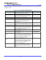
Table 2.3.1-1 SYSTEM ID (PGM 100)
Btn
DISPLAY
1
COUNTRY CODE
1
2
CUSTOMER SITE NAME
REMARK
Refer to Table 2.3.1-2 below. Note system
must be re-initialized if changed.
Refer to Table 2.1.2-1 for alphanumeric dialpad entries.
3
MY AREA CODE
Enter the area code of the installed site.
4
NUMBERING PLAN(1-8)
Refer to Appendix B for details of Numbering
Plan selection.
5
SYSTEM ID
SYSTEM RESET
Returns the System Id to default.
2-3
RANGE
DEFAULT
4 digits
1
23
character
6 digits
1-8
1
IPECS
Release 5
Admin & Maintenance
Issue 5.0
Table 2.3.1-2 COUNTRY CODES
COUNTRY
CODE
COUNTRY
CODE
COUNTRY
CODE
America
Bahrain
Bolivia
Burma
China (Taiwan)
Costa Rica
Denmark
El Salvador
Finland
Germany
Guam
Haiti
India
Iraq
Italy
Kenya
Liberia
Luxembourg
Mexico
Netherlands
Norway
Panama
Peru
Qatar
Singapore
Sri Lanka
Switzerland
Turkey
Uruguay
1
973
591
95
886
506
45
503
358
49
671
509
91
964
39
254
231
352
52
31
47
507
51
974
65
94
41
90
598
Argentina
Bangladesh
Brazil
Cameroon
CIS
Cyprus
Ecuador
Ethiopia
France
Ghana
Guatemala
Honduras
Indonesia
Ireland
Japan
Korea
Libya
Malaysia
Monaco
New Zealand
Oman
P.N.G
Philippines
Saudi Arabia
South Africa
Swaziland
Thailand
U.A.E.
Venezuela
54
880
55
237
7
357
593
251
33
233
502
504
62
353
81
82
218
60
377
64
968
675
63
966
27
268
66
971
58
Australia
Belgium
Brunei
Chile
Colombia
Czech
Egypt
Fiji
Gabon
Greece
Guyana
Hong Kong
Iran
Israel
Jordan
Kuwait
Malta
Morocco
Nigeria
Pakistan
Paraguay
Portugal
Senegal
Spain
Sweden
Tunisia
United Kingdom
Y.A.R.
61
32
673
56
57
42
20
679
241
30
592
852
98
972
962
965
356
212
234
92
595
351
221
34
46
216
44
967
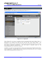
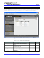
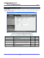
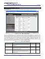
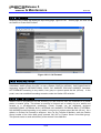
2.3.2 NUMBERING PLANS DATA – PGM CODES 102 to 1092.3.2.1 System IP Address Plan -PGM Code 102The System IP Address Plan sets several IP addresses including the MFIM IP address required for
external VoIP calls, the IP address for the router, and the system’s internal private IP address Plan.
Note that the MFIM and Router addresses and sub-net mask must be a routable IP address for
access to an external VoIP network, remote access by a gateway Module or terminal and remote
Web access. The VOIM (Voice over IP gateway Module) must also have a routable IP address for
access to/from an external VoIP network or remote user.
When Automatic IP Assignment, button 7, is enabled, the system will assign IP addresses to each
local gateway Module and terminal using the assigned System IP address range. These
addresses are used for communications between the system and other Modules and terminals.
The MFIM may be installed on a LAN that is segmented by two separate private IP address
schemes. This segmenting technique is often used to separate voice and data devices. However,
with this segmenting technique, the MFIM would normally treat the segmented gateway Modules
and Terminals such as iPECS SoftPhones, as remote devices, using valuable WAN bandwidth.
2-4
IPECS
Release 5
Admin & Maintenance
Issue 5.0
Assigning the MFIM an IP address from the second segment (“Second Sys IP address”) permits
the MFIM to communicate with the devices directly over the LAN.
iPECS can be installed behind a NAPT server, if the NAPT server provides fixed address
translation and port forwarding to the system. In this case, the system will employ the “Firewall IP
address”, button 10, as the fixed public IP address for communication with remote devices. This
address must be assigned as the MFIM address in the remote device.
In some situations, specifically when multiple iPECS systems are installed on the same LAN, it
may be advantageous to register devices employing MAC addresses in place of the “plug & play”
mechanism using the MFIM registration DIP-switch. The system allows a range of MAC
addresses to be entered allowing devices with a MAC address in the range to register with the
iPECS regardless of the Registration switch position. For convenience, two ranges can be defined
in the database.
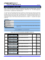
PROCEDURE:
SYSTEM IP ADDRESS PLAN
1.
Press the [PGM] button and dial 102.
PRESS FLEX KEY (1-18)
Select the desired button 1~18, refer to Table 2.3.2-1.
See Table 2.3.2-1
DISPLAY
Use the dial-pad to enter desired IP addresses. Use an “*” to enter a dot (“.”)
Press the [SAVE] button to store IP address entries.
Table 2.3.2-1 SYSTEM IP ADDRESS PLAN (PGM 102)
Btn
DISPLAY
DEFAULT
1
MFIM/E IP ADDRESS
---.---.---.---
10.10.10.2
2
MFIM/E SUB NET MASK
255.255.255.000
255.255.0.0
3
ROUTER IP ADDRESS
---.---.---.---
10.10.10.1
4
SYSTEM START IP ADDRESS
10.10.10.10
10.10.10.10
5
SYSTEM END IP ADDRESS
10.10.10.254
10.10.254.25
6
SYSTEM SUB NET MASK
255.255.255.000
255.255.0.0
7
AUTOMATIC IP ASSIGN
(1:ON/0:OFF): ON
ON
4
REMARK
Public IP Address required for remote user and external VoIP
network access. IPv4 format.
IP Address of router for external network (WAN/IP) access.
Required for shared voice and data LAN, external VoIP and
remote Web access.
Start of range for private IP addresses assigned by the
system to Modules/Terminals.
End of range for private IP addresses assigned by the system
to Modules/Terminals.
The system will automatically assign IP addresses to modules
and terminals (ON) or, when OFF, IP addresses are assigned
manually in PGM CODE 103 Device IP Address Plan.
2-5
IPECS
Release 5
Admin & Maintenance
When devices are located on a different private address on
the same net, enter the MFIM IP address for the second LAN.
8
SECOND SYS IP ADDRESS
0.0.0.0
9
SECOND SYS SUB NET MASK
255.255.0 .0
10
FIREWALL IP ADDRESS
0 .0 .0 .0
11
FIRST START MAC ADDR
000000000000
00.00.00.00.
FIRST END MAC ADDR
000000000000
00.00.00.00.
SECOND START MAC ADDR
000000000000
00.00.00.00.
SECOND END MAC ADDR
000000000000
00.00.00.00.
12
13
14
Issue 5.0
0.0.0.0
255.255.0.0
0.0.0.0
00.00
00.00
00.00
00.00
15
SYSTEM IP ADDRESS PLAN
SYSTEM RESET
16
MFIM/E LAN2 M IP ADDR
0.0.0.0
17
MFIM/E LAN2 S IP ADDR
0.0.0.0
18
MFIM DNS IP ADDR
0.0.0.0
When the system is installed behind a NAPT server, the fixed
IP Address provided by the NAPT server must be assigned in
this field. Also, use this IP address for the MFIM address in
remote devices.
A range of MAC addresses can be entered to register devices
regardless of the 3rd DIP-switch. This entry is the start
address of the first range.
A range of MAC addresses can be entered to register devices
regardless of the 3rd DIP-switch. This entry is the end
address of the first range.
A range of MAC addresses can be entered to register devices
regardless of the 3rd DIP-switch. This entry is the start
address of the second range.
A range of MAC addresses can be entered to register devices
regardless of the 3rd-DIP switch. This entry is the end address
of the second range.
Returns System IP Address Plan to default values.
When redundancy is to be supported for the MFIM, the master
and slave are connected via the LAN2 port. All 8 wires in the
cable must be terminated to the RJ45. The master IP address
can be assigned here. When the direct connection mode is
employed for redundancy, the field is ignored.
When redundancy is to be supported for the MFIM, the master
and slave are connected via the LAN2 port. All 8 wires in the
cable must be terminated to the RJ45. The slaver IP address
can be assigned here. When the direct connection mode is
employed for redundancy, the field is ignored.
IP Address of Domain Name Server, which iPECS will use to
resolve urls to an IP address. The DNS provides the
resolution after receiving the name from iPECS.
2.3.2.2 Device IP Address Plan -PGM Code 103As gateway Modules and terminals register to the iPECS, a gateway number is assigned, which
indicates the order of registration. Also, based on the type of device (CO/IP gateway, Terminal,
MISC/VSF/WTIM gateway) the system assigns a logical Sequence Number. Thus, Sequence
Numbers for CO/VOIM gateway Modules, Terminals and the MISC/VSF gateway are
independently assigned based on the type of gateway. These Sequence Numbers are employed
to provide a relationship between the physical MAC address and the logical port numbers of the
device.
For the RSGM, the CO Line port is assigned a CO/IP gateway Sequence Number and the iPECS
Phone and SLT port are assigned Terminal Sequence Numbers.
2-6
IPECS
Release 5
Admin & Maintenance
Issue 5.0
The system may assign a default private IP address to each Sequence Number. If desired, this
program may be used to modify the assigned IP address for each gateway Module and iPECS
Phone.
Each local gateway Module and terminal can be assigned for “Direct Send”. With Direct Send
enabled, the system will employ the Ethernet MAC address, layer 2 switching to eliminate the need
for IP traffic overhead, reducing overall LAN traffic.
The system normally employs IP multi-cast protocol to respond to a registration request from a
gateway Module or terminal. When the device is separated from the system by a router, the
system must use the IP uni-cast protocol. This is established by the “Local Device” assignment.
When disabled (Off), the system will send an IP uni-cast message to the device in response to a
registration request.
PROCEDURE:
DEVICE IP ADDRESS PLAN
1.
Press the [PGM] button and dial 103.
PRESS FLEX KEY (1-6)
See Table 2.3.2.2-1
DISPLAY
Select the desired Flex button.
Button 1: CO & VOIP gateway Modules
Button 2: Stations
Button 3: MISC
Button 4: VSF & VMIM
Button 5: MCIM
Button 6: SYSTEM RESET
Button 7: WTIM
Use the [VOL UP] and [VOL DOWN] buttons to see next/previous IP Address.
Refer to Table 2.3.2.2-1 for display information.
Press Flex 1~6 to select the Sub-menu item desired. See Table 2.3.2.2-1.
Button 1: IP address
Button 2: MAC address
Button 3: Direct Send
Button 4: Local Device
Button 5: CPU Type
Button 6: Device (Board) ID
Use the dial-pad to enter desired data. For IP and MAC addresses, an “*” is used
to enter a dot (“.”)
Press the [SAVE] button to store the data entry.
2-7
IPECS
Release 5
Admin & Maintenance
Issue 5.0
Table 2.3.2.2-1 MODULE & STATION ADDRESS PLAN (PGM 103)
Btn
1-1
SET IP ADDRESS
VOIP 1 : 10.10.10.2
FEATURE
LCD shows:
Line 1 Sequence Number, 2 or 3 digits
MAC Address, 12 digits
Line 2 Module Type, 4 characters
First Logical port number
IP Address, 7~12 digits
Use Flex button 1 to set the device’s IP address in
IP v4 format.
1-2
SET MAC ADDRESS
001-001 :0090A00175A2
Use Flex button 2 to enter the device’s MAC
address in the system memory.
1-3
DIRECT SEND (MAC)
(1:ON/0:OFF): ON
1-4
LOCAL DEVICE
(1:ON/0:OFF): ON
1-5
CPU TYPE
Use Flex button 3 to enable/disable Direct Send
mode, which employs layer 2 switching to local
devices.
Use Flex button 4 to enable/disable Local Device
Mode, which defines the device as on a common
LAN with the MFIM.
Flex button 5 displays the type of CPU employed
in the device.
1
DISPLAY
001-001
VOIP 1
:0090A00175A2
:10 .10 .10 .2
MS828
1-6
DEVICE(BOARD) ID
GW-VOIP
Flex button 6 displays the GW type designation.
001-004
KTU 100
2-1
SET IP ADDRESS
KTU 100 :10.10.10.11
LCD shows:
Line 1 Sequence Number, 3 digits
MAC Address, 12 digits
Line 2 Station Type, 3 characters
Station Number, 2~4 digits
IP Address, 7~12 digits
Use Flex button 1 to set the device’s IP address in
IP v4 format.
2-2
SET MAC ADDRESS
001-002 :00405A0175A3
Use Flex 2 button to enter the device’s MAC
address into system memory.
2-3
DIRECT SEND (MAC)
(1:ON / 0 :OFF): ON
2-4
LOCAL DEVICE
(1:ON / 0 :OFF): ON
2-5
CPU TYPE
Use Flex button 3 to enable/disable Direct Send
mode, which employs layer 2 switching to local
devices.
Use Flex button 4 to enable/disable Local Device
Mode, which defines the device as on a common
LAN with the MFIM.
Flex button 5 displays the type of CPU employed
in the device.
2
: 00405A0175A3
:10.10.10.11
T2
2-6
3
DEVICE(BOARD) ID
LIP-24D
Flex button 6 displays the terminal type
designation.
001-002
:00405A017615
MISC :10.10.10.10
LCD shows:
Line 1 Sequence Number, 2 digits
MAC Address, 12 digits
Line 2 “MISC”
IP Address, 7~12 digits
2-8
DEFAULT
CO & VoIP Gateway
Module IP address
set sequentially,
from the range in
PGM 102.
10.10.10.10~254
None
ON
ON
Station IP address
set sequentially,
from the range in
PGM 102.
10.10.10.10~254
None
ON
ON
IP address of Misc.
functions in the
system’s MFIM set
automatically,
IPECS
Release 5
Admin & Maintenance
Btn
3-1
SET IP ADDRESS
MISC :10.10.10.10
FEATURE
Use Flex button 1 to set the device’s IP address in
IP v4 format.
3-2
SET MAC ADDRESS
001-003 : 00405A017615
Use Flex button 2 to enter the device’s MAC
address into system memory.
3-3
DIRECT SEND (MAC)
(1:ON / 0 :OFF): ON
3-4
LOCAL DEVICE
(1:ON / 0 :OFF):
Use Flex button 3 to enable/disable Direct Send
mode, which employs layer 2 switching to local
devices.
Use Flex button 4 to enable/disable Local Device
Mode, which defines the device as on a common
LAN with the MFIM.
Flex button 5 displays the type of CPU employed
in the device.
3-5
DISPLAY
ON
CPU TYPE
T2
3-6
DEVICE(BOARD) ID
GW-MISC
Flex button 6 displays the MISC type designation.
001-002
:00405A017635
VSF :10.10.10.10
4-1
SET IP ADDRESS
VSF :10.10.10.10
LCD shows:
Line 1 Sequence Number, 2 digits
MAC Address, 12 digits
Line 2 “VSF” or “VMIM”
IP Address, 7~12 digits
Use Flex button 1 to set the device’s IP address in
IP v4 format.
4-2
SET MAC ADDRESS
001-003 : 00405A017615
Use Flex button 2 to enter the device’s MAC
address into system memory.
4-3
DIRECT SEND (MAC)
(1:ON / 0 :OFF): ON
4-4
LOCAL DEVICE
(1:ON / 0 :OFF):
T2
Use Flex button 3 to enable/disable Direct Send
mode, which employs layer 2 switching to local
devices.
Use Flex button 4 to enable/disable Local Device
Mode, which defines the device as on a common
LAN with the MFIM.
Flex button 5 displays the type of CPU employed
in the device.
DEVICE(BOARD) ID
GW-MISC
Flex button 6 displays the type designation, VSF
or VMIM.
001-003
: 00405A017666
MCIM : 10:10:10:12
LCD shows:
Line 1 Sequence Number, 2 digits
MAC Address, 12 digits
Line 2 “VSF” or “VMIM”
IP Address, 7~12 digits
5-1
SET IP ADDRESS
MCIM :10.10.10.12
Use Flex button 1 to set the device’s IP address in
IP v4 format.
5-2
SET MAC ADDRESS
001-003 : 00405A017666
Use Flex button 2 to enter the device’s MAC
address into system memory.
4
4-5
4-6
5
ON
CPU TYPE
2-9
Issue 5.0
DEFAULT
10.10.10.10~254
None
ON
ON
IP address of Misc. &
VSF functions in the
system’s MFIM set
automatically.
10.10.10.10~254
None
ON
ON
MCIM Gateway
Module IP address
set sequentially,
from the range in
PGM 102.
10.10.10.10~254
None
IPECS
Release 5
Admin & Maintenance
Btn
DISPLAY
5-3
DIRECT SEND (MAC)
(1:ON / 0 :OFF): ON
5-4
LOCAL DEVICE
(1:ON / 0 :OFF):
5-5
ON
CPU TYPE
T2
FEATURE
Use Flex button 3 to enable/disable Direct Send
mode, which employs layer 2 switching to local
devices.
Use Flex button 4 to enable/disable Local Device
Mode, which defines the device as on a common
LAN with the MFIM.
Flex button 5 displays the type of CPU employed
in the device.
DEVICE(BOARD) ID
GW-MCIM
Flex button 6 displays the type designation,
MCIM.
6
DEVICE IP ADDRESS PLAN
SYSTEM RESET
If the [SAVE] button is pressed, the system will
reset and restart.
7
001-015
: 00405A142C67
WTI4 : 10:10:10:14
5-6
Issue 5.0
DEFAULT
ON
ON
7-1
SET IP ADDRESS
WTI4 :10.10.10.14
LCD shows:
Line 1 Sequence Number, 2 digits
MAC Address, 12 digits
Line 2 “WTI4 ” or “WTI8”
IP Address, 7~12 digits
Use Flex button 1 to set the device’s IP address in
IP v4 format.
7-2
SET MAC ADDRESS
001-015 : 00405A142C67
Use Flex button 2 to enter the device’s MAC
address into system memory.
None
7-3
ARP
(0:ON/1:OFF):
Use Flex button 3 to enable/disable ARP, ARP
OFF enables Direct Send, which employs layer 2
switching to local devices.
Use Flex button 4 to disable/enable Local Device
Mode, which defines the device as on a common
LAN with the MFIM. MCAST enables Local
Device Mode
Flex button 5 displays the type of CPU employed
in the device.
OFF
OFF
7-4
REGISTRATION
(0:UCAST/1:MCAST):MCAST
7-5
CPU TYPE
MS828
7-6
DEVICE(BOARD) ID
GW-WTIM4
WTIM Gateway Module
IP address set
sequentially, from the
range in PGM 102.
10.10.10.10~254
MCAST
Flex button 6 displays the type designation,
WTIM4 or WTIM8,
2.3.2.3 CO Gateway Sequence Number -PGM Code 104Each CO/IP gateway Module is assigned a Sequence Number for each Ethernet MAC address.
The LGCM4, DID and BRIM each have two MAC addresses and thus are assigned two sequence
numbers, Other gateway Modules and the system VOIP channels all have single MAC addresses
and thus a single Sequence number is assigned. The system uses the Sequence Number to
assign logical (software) port numbers. This Sequence Number relates the hardware and software
port numbers for each gateway Module using the Modules MAC addresses. When employing a
Main Cabinet, it may be desirable to have the logical and physical (RJ21X appearances) port
numbers in agreement. This may be accomplished by assigning Cabinet slot numbers matching
the appropriate Sequence Numbers. This also may be accomplished by proper installation
2-10
IPECS
Release 5
Admin & Maintenance
Issue 5.0
sequence of the gateway modules. Table 2.3.2.3-1 provides the analog CO Line and ISDN Line
port numbers based on the physical RJ-21X terminations on the Main Cabinet back plane.
PROCEDURE:
001 002 003 004 005 006
1.
Press the [PGM] button and dial 104.
001 005 003 006 002 004
001 002 003 004 005 006
001 005 003 006 002 004
001 002 003 004 005 006
001 002 003 004 005 006
Press the Flex button (1~6) for the desired Sequence Number, use the [VOL UP]
and [VOL DOWN] buttons for the next/previous set of six Sequence Numbers.
Using the dial pad, enter new slot numbers. Note slot numbers cannot be
duplicated and duplicates will cause an error. The [SPEED] button may be
used to erase the slot number associated with the selected Sequence
Number.
Press the [SAVE] button to store the new Slot data.
Table 2.3.2.3-1 RJ-21X TERMINATIONS
SLOT
CO LINE PORT
1
1~4
2
5~8
3
9 ~ 12
4
13 ~ 16
5
17 ~ 20
6
21~ 24
7
25 ~ 28
8
29 ~ 32
2.3.2.4 Flexible Station Numbering Plan -PGM Code 105As with gateway Modules, each iPECS Phone and SLT is assigned a Sequence Number during
the registration process. The station Sequence Number is a 3-digit number starting at 001, which
is incremented as each terminal device is registered. At registration, station numbers increment
sequentially with the Sequence Number and are assigned starting at station 100 for Sequence
Number 001. The Station Numbering Plan allows the station numbers to be two (2) to four (4)
digits in length.
PROCEDURE:
001 002 003 004
1.
Press the [PGM] button and dial 105.
100 101 102 103
001 002 003 004
100 101 102 103
Use either of the two methods below to change the station number associated with
a Sequence Number. Note pressing the [SPEED] button twice clears all
station number assignments. The [VOL UP] & [VOL DOWN] buttons are
used to view the next/previous 4 station Sequence Numbers
2-11
IPECS
Release 5
Admin & Maintenance
Issue 5.0
Range entry:
Using the dial-pad, enter a station number range (first & last station number). The
two station numbers must be of the same length, 2~4 digits. The range
assignment begins with the first station number shown by the LCD and
continues to the end of the entered range.
Single entry:
4.1
Press Flex button 1~4 to select the desired Sequence Number from the four
shown by the LCD.
4.2
Dial new station number.
Press the [SAVE] button to store the new station numbers.
2.3.2.5 Flexible Numbering Plan part A to D -PGM Codes 106 to 109Feature dial codes for the system can be assigned using the system’s Flexible Numbering Plan.
Feature codes should be one (1) to four (4) digits in length and must not conflict. For example,
Feature dial codes 53 and 536 represent a conflict. The system will generate error tone and will
not update the database. Table 2.3.2.5-1 to Table 2.3.2.5-4 below show the defaults for the 1st
base Numbering Plan. Appendix B provides the default values for each of the eight base
Numbering Plans, select the base Numbering Plan in PGM CODE 100.
PROCEDURE:
FLEX NUMBERING PLAN A
PRESS FLEX KEY (01-24)
Refer to Table 2.3.2.5-1to -4
DISPLAY
1.
Press the [PGM] button and dial:
106 for part A
107 for part B
108 for part C
109 for part D.
Select the desired button (01~24); refer to Table 2.3.2.5-1 to Table 2.3.2.5-4 for
PROGRAM CODES 106 to 109 respectively.
Use the dial-pad to enter desired data. Where a range is required, input the first
and last numbers in the range.
Press the [SAVE] button to store the new Numbering Plan data.
Table 2.3.2.5-1 FLEXIBLE NUMBERING PLAN PART A (PGM 106)
Btn
DISPLAY
FEATURE
DEFAULT
iPECSiPECS-50
Micro
MFIM100
1
INT PAGE ZONES
START& END:501-510
Internal Page Zone
access dial codes.
2
INT ALL CALL
ENTER NEW #:543
Internal All Call Page
access dial code.
2-12
MFIM
300
MFIM
600
MFIM
1200
501~510
501~510
501~535
501~535
301~400
543
543
543
543
543
IPECS
Release 5
Admin & Maintenance
Btn
DISPLAY
FEATURE
Issue 5.0
DEFAULT
iPECSiPECS-50
Micro
MFIM100
MFIM
300
MFIM
600
MFIM
1200
3
MEET ME PAGE
ENTER NEW #:544
Meet-Me-Page
answer dial code.
544
544
544
544
544
4
EXT PAGE ZONE 1
ENTER NEW #:545
n/a
545
545
545
545
5
EXT PAGE ZONE 2
ENTER NEW #:546
n/a
546
546
546
546
6
EXT ALL CALL
ENTER NEW #:548
n/a
548
548
548
548
7
ALL CALL PAGE
ENTER NEW #:549
External Page Zone 1
access dial code. Not
available in iPECSMicro
External Page Zone 2
access dial code. Not
available in iPECS-50
and iPECS-Micro
External All Call Page
access dial code. Not
available in iPECSMicro
All Call Page access
dial code.
549
549
549
549
549
8
SMDR ACT CODE ENTER
ENTER NEW #:550
Dial code to signify the
start of an SMDR
Account Code.
550
550
550
550
550
9
FLASH CMD TO CO
ENTER NEW #:551
Dial code to generate
a Flash on the active
CO Line.
551
551
551
551
551
10
SLT LAST SPD DIAL
ENTER NEW #:552
SLT Last Number
Redial feature access
dial code.
552
552
552
552
552
11
DND
ENTER NEW #:553
Dial code to activate
Do-Not-Disturb.
553
553
553
553
553
12
CALL FWD
ENTER NEW #:554
Dial code to activate
Call Forward.
554
554
554
554
554
13
SPD DIAL PGM
ENTER NEW #:555
Speed Dial
programming access
dial code for SLTs.
555
555
555
555
555
14
MSG WAIT ENABLE
ENTER NEW #:556
Dial code to activate a
Message Wait/Call
Back.
556
556
556
556
556
15
MSG WAIT RETURN
ENTER NEW #:557
Dial code to return a
Message Wait/Call
Back.
557
557
557
557
557
16
SPD DIAL ACCESS
ENTER NEW #:558
SLT Speed Dial
access code.
558
558
558
558
558
17
DND/FWD CANCEL
ENTER NEW #:559
Dial code to cancel
DND/FWD/MSG Wait.
559
559
559
559
559
18
CO SYS HOLD
ENTER NEW #:560
Dial code to place a
CO call on System
Hold.
560
560
560
560
560
2-13
IPECS
Release 5
Admin & Maintenance
Btn
DISPLAY
FEATURE
Issue 5.0
DEFAULT
iPECSiPECS-50
Micro
MFIM100
MFIM
300
MFIM
600
MFIM
1200
19
SLT PGM MODE ENTER
ENTER NEW #:561
User program mode
entry dial code for
SLTs.
561
561
561
561
561
20
ATTD UNAVAILABLE
ENTER NEW #:562
562
562
562
562
562
21
ALARM RESET
ENTER NEW #:565
Dial code to place
attendant in the
“unavailable” mode,
attendant only.
Dial code to terminate
Alarm contact signal.
565
565
565
565
565
22
GROUP CALL PICK-UP
ENTER NEW #:566
Group Call Pick-up
dial code.
566
566
566
566
566
23
UNIVERSAL NIGHT ANSWER
ENTER NEW #:567
Universal Night
Answer dial code.
567
567
567
567
567
24
ACCOUNT CODE WITH BIN
ENTER NEW #:568
Dial code for entering
an Account code.
568
568
568
568
568
Table 2.3.2.5-2 FLEXIBLE NUMBERING PLAN PART B (PGM 107)
Btn
DISPLAY
FEATURE
DEFAULT
iPECSiPECS-50
Micro
MFIM100
MFIM
300
MFIM
600
MFIM
1200
1
WALKING COS
ENTER NEW #:569
Dial code to activate
Walking Class-ofService.
569
569
569
569
569
2
ACD AGENT ON/OFF DUTY
ENTER NEW #:571
Dial code to toggle ACD
Agent or Supervisor ON
and OFF duty.
571
571
571
571
571
3
ACD SUPERVISOR LOGIN
ENTER NEW #:572
Supervisor login dial
code.
572
572
572
572
572
4
ACD SUPERVISOR LOGOUT
ENTER NEW #:573
Supervisor logout dial
code.
573
573
573
573
573
5
ACD HELP CODE
ENTER NEW #:574
574
574
574
574
574
6
ACD CALLS IN QUEUE
ENTER NEW #:575
Agent dial code
requesting Supervisor
help, and Supervisor
Help request Response
code.
Dial code to display
calls in queue.
575
575
575
575
575
7
ACD SUPERVISOR STATUS
ENTER NEW #:576
Dial code to display
group status.
576
576
576
576
576
8
ACD SUPERVISOR MONITOR
ENTER NEW #:577
Dial code to activate
Supervisor monitor.
577
577
577
577
577
2-14
IPECS
Release 5
Admin & Maintenance
Btn
DISPLAY
FEATURE
Issue 5.0
DEFAULT
iPECSiPECS-50
Micro
MFIM100
MFIM
300
MFIM
600
MFIM
1200
9
ACD REROUTE QCALL ANS
ENTER NEW #:578
Dial code to reroute call
after answer.
578
578
578
578
578
10
ACD REROUTE QCALL NO AN
ENTER NEW #:579
Dial code to reroute call
prior to answer.
579
579
579
579
579
11
CAMP-ON ANSWER
ENTER NEW #:600
Dial code to answer a
Camped On call.
600
600
600
600
600
12
CALL PARK LOCATIONS
START&END#:601-610
Dial code to
place/retrieve a call in a
Park location.
601~610
601~610
601~619
601~699
601~69
STA GRP PILOT NUMBER
START&END #:620-659
Station group pilot
numbers.
620~631
14
STA USER VSF FEATURES
ENTER NEW #:66
VSF feature access dial
code.
66
66
*66
*66
*66
15
CALL COVERAGE RING
ENTER NEW #:67
Code for Call Coverage
button.
67
67
67
67
76
16
DIRECT CALL PICK-UP
ENTER NEW #:7
Dial code to activate
Directed Call Pick-up.
7
7
7
7
*77
17
ACCESS CO GROUP FEAT
START&END:801-820
Dial code to access a
CO Line or IP channel
from a CO/IP group.
801~820
801~820
801~872
801~872
n/a
18
ACCESS IND CO/IP FEAT
START&END:88
Dial code to access a
specific CO Line.
88001
~
19
ACCESS HELD CO/IP FEAT
ENTER NEW:8*
20
13
9
620~659
620~667
620~667
401~50
0
8801
8801
88001 ~
88001 ~
~8805
~8842
88200
88400
Dial code to access last
held CO Line or IP
channel from Hold.
8*
8*
8*
8*
8*
ACCESS HELD IND CO/IP
ENTER NEW #:8#
Dial code to access a
specific CO Line/IP
channel from Hold.
8#
8#
8#
8#
8#
21
ACCESS CO IN 1ST CO GRP
ENTER NEW #:9
Dial code to access the
1st available CO Line in
any accessible group.
9
9
9
9
9
22
ATTENDANT CALL
ENTER NEW #:0
Dial code to call an
Attendant.
0
0
0
0
0
23
VM MSG WAIT ENABLE
ENTER NEW #:*8
Dial code for external
Voice mail to activate
Message Wait
indication.
*8
*8
*8
*8
*8
24
VM MSG WAIT CANCEL
ENTER NEW #:*9
Dial code for external
Voice Mail to deactivate
Message Wait
indications.
*9
*9
*9
*9
*9
88600
2-15
IPECS
Release 5
Admin & Maintenance
Issue 5.0
Table 2.3.2.5-3 FLEXIBLE NUMBERING PLAN PART C (PGM 108)
Btn
DISPLAY
FEATURE
DEFAULT
IPECS-50
MFIM100
MFIM
300
MFIM
600
MFIM
1200
1
DOOR OPEN 1
ENTER NEW #:#*1
Dial code to activate Door 1
contact (open door 1)
#*1
#*1
#*1
#*1
2
DOOR OPEN 2
ENTER NEW #:#*2
#*2
#*2
#*2
#*2
3
DOOR OPEN 3
ENTER NEW #:#*3
#*3
#*3
#*3
4
DOOR OPEN 4
ENTER NEW #:#*4
Dial code to activate Door 2
contact (open door 2). Not
available in iPECS-50.
Dial code to activate Door 3
contact (open door 3)
MFIM300 & MFIM600 only.
Dial code to activate Door 4
contact (open door 4)
MFIM300 & MFIM600 only.
#*4
#*4
#*4
Table 2.3.2.5-4 FLEXIBLE NUMBERING PLAN PART D (PGM 109)
Btn
DISPLAY
FEATURE
DEFAULT
iPECSMFIM
50/Micro 300
MFIM100
1
MCID REQUEST
ENTER NEW #:*0
2
AME FEATURE
ENTER NEW #: 564
Dial code to activate Malicious Call ID
Request in ISDN Supplementary
service. Not available in USA version.
Dial code to assign an Answering
Machine Emulation Flex button.
3
US-CONF TMR EXTENSION
ENTER NEW #:##
4
PTT GROUP LOGIN/OUT
ENTER NEW #:#0
5
ACD AGENT P LOGIN
ENTER NEW #:…
6
MFIM
600
MFIM
1200
*0
*0
*0
*0
564
564
564
564
Dial code to extend Unsupervised
conference time.
##
##
##
##
Push-To-Talk group login and logout
dial code. The station must have a
PTT button for proper operation.
ACD Agent Primary Login code
#0
#0
#0
#0
581
581
581
581
ACD AGENT P LOGOUT
ENTER NEW #:…
ACD Agent Primary Logout code
582
582
582
582
7
ACD AGENT S LOGIN
ENTER NEW #:…
ACD Agent Secondary Login code
583
583
583
583
8
ACD AGENT S LOGOUT
ENTER NEW #:…
ACD Agent Secondary Logout code
584
584
584
584
9
ACD AGENT WRAPUP END
ENTER NEW #:…
ACD Agent wrap-up end code
585
585
585
585
2-16
IPECS
Release 5
Admin & Maintenance
Btn
DISPLAY
FEATURE
Issue 5.0
DEFAULT
iPECSMFIM
50/Micro 300
MFIM100
MFIM
600
MFIM
1200
586
586
586
586
ENTER INTO CONF-ROOM
ENTER NEW #:59
When Central Control networking
(TNET) is employed, a station can be
manually logged in or out of the
Central system using this code.
Code for a station to enter a
conference room.
59
59
59
59
12
ENTER INTO CONF-GROUP
Code to open a conference group.
68
68
68
68
13
STATION ICR
Code to activate Station ICR.
587
587
587
587
14
PICK UP GROUP PICK-UP
Pick Up Group Call Pick-up dial code.
588
588
588
588
15
EMERGENCY PAGE
ENTER NEW #:*589
Code for emergency page
589
589
589
589
16
REMOTE MEX CONTROL
ENTER NEW #:580
Code to control the mobile extension
settings remotely
580
580
580
580
17
ALL GR AGENT ON/OFF DUTY
ENTER NEW #:58*
Code to change the state of the Agent
ON/Off duty in all hunt group
58*
58*
58*
58*
10
TNET CM LOGIN/OUT
ENTER NEW #:586
11
2.3.3 STATION DATA – PGM CODES 110-1252.3.3.1 Station Type -PGM Code 110Each station is assigned a type, which is used by the system to recognize the station’s capabilities
and default Flex button configuration. In addition, for the iPECS DSS/BLF Consoles, the
associated station number is identified here. Note that the maximum of four (4) LIP-8012LSS DSS
Consoles can be associated and connected to a station.
PROCEDURE:
STATION TYPE ASSIGN
1.
Press the [PGM] button and dial 110.
ENTER STA RANGE
100-110 F1:TY F2:ASC
IPKTU
Use the dial-pad to enter a station range (Ex 100~110). For a single station,
enter the same number twice; use this procedure for an iPECS DSS
Console.
Select Flex button 1, to set the station type and, for iPECS DSS Consoles (types
2~4), Flex button 2 assigns the associated station.
2-17
IPECS
Release 5
Admin & Maintenance
Issue 5.0
Use the dial-pad to enter desired data:
4-1.
For Flex button 1 (TYPE), enter the station TYPE; refer to or .
100-110 F1:TY F2:ASC
IPKTU
111-111 F1:TYPE F2 :ASC
4-2.
For Flex button 2 (Associated station), enter the number of the station
used with the console. Flex button 2 is only available for iPECS DSS
Consoles (Types 2~4), see Table 2.3.3.1-3 or Table 2.3.3.1-4 for default
configurations.
DSS MAP2 : STA . . . .
Press the [SAVE] button to store the data entries.
Table 2.3.3.1-1 STATION TYPE ASSIGNMENT (PGM 110)
(iPECS-Micro)
TYPE
DESCRIPTION
IP KEYSET
DSS MAP 1
SLT (DTMF)
SLT with MSG Wait Lamp for DTMF
1
2
3
4
Table 2.3.3.1-2 STATION TYPE ASSIGNMENT (PGM 110)
(MFIM100, iPECS-50)
TYPE
DESCRIPTION
IP KEYSET
DSS MAP 1
DSS MAP 2
DSS MAP 3
SLT (DTMF)
SLT with MSG Wait Lamp for DTMF
1
2
3
4
5
6
Table 2.3.3.1-3 STATION TYPE ASSIGNMENT (PGM 110)
(MFIM300 , MFIM600 & MFIM1200)
TYPE
1
2
3
4
5
6
7
8
9
10
11
12
DESCRIPTION
IP KEYSET
DSS MAP 1
DSS MAP 2
DSS MAP 3
DSS MAP 4
DSS MAP 5
DSS MAP 6
DSS MAP 7
DSS MAP 8
DSS MAP 9
SLT (DTMF)
SLT with MSG Wait Lamp (DTMF)
2-18
IPECS
Release 5
Admin & Maintenance
Table 2.3.3.1-2 IP CONSOLE BUTTON CONFIGURATION (PGM 110)
(iPECS-Micro)
MAP
MAP 1
DEFAULT CONSOLE BUTTON CONFIGURATION
* First 12 Buttons:
Button 1: ATD Override
Button 2: All Call Page
Button 3: Call Park 1
Button 4: Station Group 1
Button 5: Camp-On
Button 6: Internal All Call Page
Button 7: Call Park 2
Button 8: Station Group 2
Button 9: [Release]
Button 10: Ext. All Call Page
Button 11: Call Park 3
Button 12: Station Group 3
iPECS-Micro
Buttons 13~38: Station Ports 100~125
Buttons 39~48: unassigned
Table 2.3.3.1-3 IP CONSOLE BUTTON CONFIGURATION (PGM 110)
(MFIM100, iPECS-50)
MAP
MAP 1
DEFAULT CONSOLE BUTTON CONFIGURATION
* First 12 Buttons:
Button 1: ATD Override
Button 2: All Call Page
Button 3: Call Park 1
Button 4: Station Group 1
Button 5: Camp-On
Button 6: Internal All Call Page
Button 7: Call Park 2
Button 8: Station Group 2
Button 9: [Release]
Button 10: Ext. All Call Page
Button 11: Call Park 3
Button 12: Station Group 3
MFIM100 & iPECS-50:
Buttons 13~48: Station Ports 100~135
MAP 2
MFIM100:
Buttons 1~34: Station Ports 136~169 (MFIM & MFIM100)
Buttons 35~48: unassigned
IPECS-50:
Buttons 1~14: Station Ports 136~149
Buttons 15~48: unassigned
MAP 3
MFIM100 & iPECS-50:
Buttons 1~42: CO Line 01~42
Buttons 43~48: unassigned.
Table 2.3.3.1-4 IP CONSOLE BUTTON CONFIGURATION (PGM 110)
(MFIM300 , MFIM600 & MFIM1200)
MAP
MAP 1
MAP 2
DEFAULT CONSOLE BUTTON CONFIGURATION
Button 1: Intrusion
Button 2: All Call Page
Button 3: Call Park 1
Button 4: Station Group 1
Button 5: Camp-On
Button 6: Internal All Call Page
Button 7: Call Park 2
Button 8: Station Group 2
Button 9: [Release]
Button 10: Ext. All Call Page
Button 11: Call Park 3
Button 12: Station Group 3
Buttons 13 ~ 48: Station Ports 100 ~ 135
Station Ports 136 ~ 183
2-19
Issue 5.0
IPECS
Release 5
Admin & Maintenance
MAP 3
MAP 4
MAP 5
MAP 6
MAP 7
MAP 8
MAP 9
Issue 5.0
Station Ports 184 ~ 231
Station Ports 232 ~ 279
Station Ports 280 ~ 327
CO Line 001 ~ 048
CO Line 049 ~ 096
CO Line 097 ~ 144
CO Line 145 ~ 192
2.3.3.2 Station Attributes – I to III -PGM Codes 111-113Station Attributes define features and functions available to the station. Generally, the entry will
turn the feature ON (enable) or OFF (disable). Refer to Table 2.3.3.2-1 to Table 2.3.3.2-3 for a
description of the features and the input required.
PROCEDURE:
1.
STATION ATT 1
ENTER STA RANGE
Press the [PGM] button and dial:
111 for Station Attributes I
112 for Station Attributes II
113 for Station Attributes III
Use the dial-pad to enter a station range (Ex. 100~110). For a single station, enter
the same number twice.
100-110 STATION ATT 1
PRESS FLEX_KEY (1-19)
Refer to Table 2.3.3.2-1 to -3
Press the desired Flex button; refer to Table 2.3.3.2-1 to Table 2.3.3.2-3.
DISPLAY
Use the dial-pad to enter desired data for the attribute setting, refer to Table
2.3.3.2-1 to Table 2.3.3.2-3.
Press the [SAVE] button to store the data entry.
Table 2.3.3.2-1 STATION ATTRIBUTES I (PGM 111)
Button
1
2
3
4
ATTRIBUTE/DISPLAY
100-110 AUTO SPKR
(1:ON/0:OFF) : ON
100-110 CALL FWD
(1:ON/0:OFF) : OFF
DESCRIPTION
Enables [SPEAKER] activation when a
CO/IP, DSS or other feature button is
pressed, no need to lift handset.
Enables Call Forward activation by the
station.
100-110 DND
(1:ON/0:OFF) : OFF
Enables DND activation by the station.
100-110 DATA SECURITY
(1:ON/0:OFF) : OFF
Disables override and camp-on tones to the
station when busy.
RANGE
0: OFF
DEFAULT
ON
1: ON
0: OFF
OFF
1: ON
0: OFF
OFF
1: ON
2-20
0: OFF
1: ON
OFF
IPECS
Release 5
Admin & Maintenance
Button
ATTRIBUTE/DISPLAY
5
100-110 HOWLING TONE
(1:ON/0:OFF) : OFF
6
7
8
100-110 NO TCH ANS
(1:ON/0:OFF) : OFF
100-110 PAGE ACCESS
(1:ON/0:OFF) : OFF
DESCRIPTION
Permits Howler tone to be sent to a SLT
when left off-hook.
Enables No-touch answer; this will
automatically connect transferred calls to the
station’s speakerphone.
Allows station to access paging.
Issue 5.0
RANGE
0: OFF
DEFAULT
ON
1: ON
0: OFF
OFF
1: ON
0: OFF
OFF
1: ON
100-110 HEADSET RING
(1:S/2:H/3:BOTH) : SPKR
This item selects device to receive incoming
ring signals, Speaker, Headset or Both.
1: Speaker
100-110 SPKR/HEAD
(1:SPKR/0:HEAD): SPKR
Selects Speakerphone mode or Headset
mode
1: Speaker
100-110 LCD DISP LED
(1:RING/0:MWI): MWI
The LCD LED, upper left of LCD, may be
used for Intercom Call ring Indication or
Message Wait Indication.
Station based LOOP LCR authorization; this
is used for LOOP LCR operation.
SPKR
2: Headset
3: Both
9
10
11
100-110 LOOP LCR ACCT
(1:ON/0:OFF) : OFF
16
100-110 ACT PTT GRP
ACTIVE PTT GROUP: 0
17
100-110 ICM GROUP
(01-15): 01
The Call Coverage feature permits an iPECS
Phone user to receive ring and answer calls
to other stations.
When a covered station rings, the {CALL
COVERAGE} button LED will flash at the
covering station and will receive ring
(immediate or delayed, 0 to 9 ring cycles).
A station must be allowed Off Net Fwd to
forward external incoming calls outside the
system or otherwise establish a CO-to-CO
connection (Unsupervised Conference).
(Except USA version)
When placing an intercom call, a user can
change the ICM signaling mode, Tone Ring
to Hands free answer mode or HF Answer to
Tone Ring.
A station can be assigned to a PTT group
and the group enabled so the station can
place and receive PTT announcements for
the group.
Assigns station to an ICM Tenancy Group,
refer to PGM CODE 125.
18
100-100 VSF/VMIM GW
GW SLOT SEQ: 29
Assigns the VSF or VMIM where messages
for the station are stored.
12
100-110 CALL COVERAGE
(1:ON/0:OFF) : OFF
13
100-110 CALL COVERAGE
DELAY RING: 0
14
100-110 OFFNET FWD
(1:DIS/0:EN):ENABLE
15
100-110 FORCED ICM
(1:ON/0:OFF) : OFF
2-21
SPKR
0: Headset
1:Ring
MWI
0:MWI
0: OFF
OFF
1: ON
0: OFF
OFF
1: ON
0~9
0
0:Enable
0
1:Disable
0: OFF
OFF
1: ON
0~9,
0
1~15
1
Seq no
IPECS
Release 5
Admin & Maintenance
Button
19
ATTRIBUTE/DISPLAY
100-100 SIP UID TBL
(00-70) : 000
DESCRIPTION
Index to SIP User ID table, PGM CODE 126, for
the station. Note PGM 126 is accessible by
Web only.
Issue 5.0
RANGE
DEFAULT
iPECS-Micro
0-26
IPECS-50
0- 50
MFIM100
0-70
MFIM300
0~300
MFIM600
0~600
MFIM1200
0~1200
20
21
22
100-100 CAMP ON TONE
(1:ON/0:OFF) : ON
Permits camp on tone to be sent to a station
when the station receives camp-on request.
100-110 SERIAL DSS
(1:EN/0:DIS):ENABLE
Assigns Serial DSS usage authority.
100-100 DLTN (00-10)
DIAL TONE (00)
Each station can choose one of eleven dial
tone sources
0: OFF
ON
1: ON
0:Disable
1
1:Enable
00: dial tone
01: Music 1,
02: Music 2,
03: VSF MOH,
04: SLTMOH1,
05: SLTMOH2,
06: SLTMOH3,
07: SLTMOH4,
08: SLTMOH5,
0
09: VSFMOH2,
10:VSFMOH3
23
100-100 RBTN (00-10)
RING BACK TONE (00)
Each station can choose one of eleven ring
back tone sources
00: ring back
0
tone
01: Music 1,
02: Music 2,
03: VSF MOH,
04: SLTMOH1,
05: SLTMOH2,
06: SLTMOH3,
07: SLTMOH4,
08: SLTMOH5,
09: VSFMOH2,
10:VSFMOH3
24
100-100 ATTACH MSG
(1:ON/0:OFF) : ON
When e-mail notification of a new VSF/VMIM
message is enabled, (PGM 236-btn 7) the email may include the voice mail as a wav file
attachment. UMS mail server IP (PGM 113btn18) & UMS Mail Address(PGM 113-btn19)
are required for proper operation.
0: OFF
ON
1: ON
Table 2.3.3.2-2 STATION ATTRIBUTES II (PGM 112)
Button
ATTRIBUTE/DISPLAY
1
100-110 CALL TIME TN
(1:ON/0:OFF) : OFF
DESCRIPTION
A tone can be sent periodically indicating the
elapsed time of an outgoing CO/IP call. The
Elapsed Call Timer (PGM CODE 180-btn 19)
determines the period between tones.
2-22
RANGE
0: OFF
1: ON
DEFAULT
OFF
IPECS
Release 5
Admin & Maintenance
Button
2
3
4
ATTRIBUTE/DISPLAY
100-110 AUTO HOLD
(1:ON/0:OFF) : OFF
100-110 TIME RESTRICT
(1:ON/0:OFF) : OFF
100-110 IND CO ACCESS
(1:EN/0:DIS) : ENABLE
DESCRIPTION
Enables Auto Hold for the station. With Auto
Hold enabled, the system will place an active
external call on hold if the user presses a CO/IP
or DSS button.
The system can automatically disconnect
outgoing calls at expiration of the Call Restrict
timer (PGM CODE 180-btn 14).
Permits stations to use dial codes to access
individual CO Lines.
Issue 5.0
RANGE
DEFAULT
0: OFF
Atd: ON
1: ON
Others:
OFF
0: OFF
OFF
1: ON
0:Disable
ENABLE
1:Enable
Permits the station to queue for the next
available Line when an All Lines Busy signal is
received.
A station can be permitted to change the CO
Line numbers (ports) associated with a CO Line
button.
Enables Ringing Line Preference for the station.
Calls that ring the telephone are answered by
going off-hook.
Allows the station access to System Speed Dial
bins.
0:Disable
0: OFF
100-110 TWO WAY RECD
(1:ON/0:OFF) : OFF
When unavailable, DID/DISA calls to the station
can be routed to the ACD Group to which the
station is a member.
When unavailable, DID/DISA calls to the station
can be routed to the Ring Group to which the
station is a member.
When allowed, the station can activate the Twoway record feature to record a conversation.
12
100-110 MSG SCRL SPD
(0 - 7) : 3
Select message scroll speed for 7000 series IP
phone (Not presently used).
0 ~7
3
13
100-110 HOT DESK STN
(1:ON/0:OFF) : OFF
A station can be assigned as a Hot Desk
phone. Users and agents can login and use
resources of the system through the Hot Desk
phone.
The system will seize this CO Line or CO group
number when the station dials ‘9’ (First
available CO access code).
When allowed, system will send CLI information
to the SLT.
0: OFF
OFF
5
6
7
8
9
10
11
14
15
100-110 CO/IP QUEUING
(1:EN/0:DIS): ENABLE
100-110 CO PGM
(1:EN/0:DIS): DISABLE
100-110 RING LINE PRE
(1:EN/0:DIS) : ENABLE
100-110 SPD ACCESS
(1:EN/0:DIS) : ENABLE
100-110 UCD GRP SVC
(1:ON/0:OFF) : OFF
100-110 RING GRP SVC
(1:ON/0:OFF) : OFF
100-110 PREFER CO/GRP
…..
100-110 SEND SLT CLI
(1:ON/0:OFF) : OFF
16
100-110 UCD PRIORITY
(0-9) : 0
17
100-110 EZ PWD LOGIN
(1:ON/0:OFF)
18
100-110 EMERGENCY CO
…..
ACD Group members may be assigned a
priority, 0-9. Members with the highest priority
are sent calls ahead of lower priority members.
This field is the same as PGM CODE 191-btn 19
for ACD Groups.
For ez Atd. enables/disables required Auth
code use.
This field defines the CO Line or Group
employed by the system to place Emergency
Assistance calls.
2-23
ENABLE
1:Enable
0:Disable
DISABLE
1:Enable
0:Disable
ENABLE
1:Enable
0:Disable
ENABLE
1:Enable
OFF
1: ON
0: OFF
OFF
1: ON
0: OFF
OFF
1: ON
1: ON
CO # or
..
CO Grp #
0: OFF
ON
1: ON
0~9
0
0: OFF
OFF
1: ON
CO # or
CO Grp #
Any CO
IPECS
Release 5
Admin & Maintenance
Button
ATTRIBUTE/DISPLAY
19
100-110 STA ACCOUNT
(1:ON/O:OFF)
20
21
22
23
24
100-100 UN CALL REC
(1:ON/0:OFF) : ON
100-100
CALL REC STA
101
100-100 VSF BK DEL
(1:ON/0:OFF) : ON
100-100
VSF BK STA
126
100-100 VSF BK PROM
(1:ON/0:OFF) : ON
DESCRIPTION
When ON, the station user must enter an
authorization code to access CO Lines.
This field enables unconditional recording of all
calls placed/received by the station.
Recordings, in .wav format, are stored at the
Phontage/UCS Client defined under button 21.
When unconditional Call recording is enabled
as above, the recording Phontage or UCS
Client station number is defined here.
A Phontage or UCS Client may monitor voice
messages for another station as a back up.
The Phontage or UCS Client will include the
message count for the station in the Voice
message count. When enabled here, the
Phontage/UCS Client may delete messages for
the station.
A Phontage or UCS Client may monitor voice
messages for another station as a back up.
The Phontage or UCS Client will include the
message count for the station in the Voice
message count. This field defines the
Phontage or UCS Client station number that will
be used as the VSF/VMIM back up.
Enables a Phontage or UCS Client to backup
VSF Prompts.
Issue 5.0
RANGE
0: OFF
DEFAULT
OFF
1: ON
0: OFF
OFF
1: ON
station
0: OFF
OFF
1: ON
station
0: OFF
OFF
1: ON
Table 2.3.3.2-3 STATION ATTRIBUTES III (PGM 113)
Button
1
2
3
4
5
6
7
8
ATTRIBUTE/DISPLAY
100-110 ADMIN
(1:EN/0:DIS) : ENABLE
DESCRIPTION
Enables station access to the System Database.
RANGE
0:Disable
Permits station access to the built-in AA/VM.
100-110 GROUP LISTEN
(1:EN/0:DIS) : DISABLE
Enables Group Listen feature, audio is sent to
both the handset and speaker with the handset
microphone active and speakerphone
microphone OFF.
Enables intrusion to gain access to an active
CO/IP call.
0:Disable
100-110 SMDR HIDE
(1:EN/0:DIS) : DISABLE
Enables hiding dialed digits in SMDR output.
0:Disable
100-110 VOICE OVER
(1:EN/0:DIS) : ENABLE
Enables use of Voice Over by station.
100-110 PRIME LINE
(1:HOT/0:WARM) : WARM
Enables Delayed Prime Line (Idle Line)
activation, see PGM CODE 121, Idle Line
Selection and PGM CODE 182-btn 6 for Prime
Line timer.
Assigns station to receive Alarm/Doorbell signal.
100-110 ALARM/DOORBEL
(1:EN/0:DIS) : DISABLE
ENABLE
1:Enable
100-110 VSF ACCESS
(1:EN/0:DIS) : DISABLE
100-110 OVERRIDE
(1:EN/0:DIS) : DISABLE
DEFAULT
0:Disable
ENABLE
1:Enable
DISABLE
1:Enable
0:Disable
DISABLE
1:Enable
DISABLE
1:Enable
0:Disable
ENABLE
1:Enable
1: HOT
0:Disable
1:Enable
2-24
WARM
2: WARM
DISABLE
IPECS
Release 5
Admin & Maintenance
Button
9
10
11
12
13
ATTRIBUTE/DISPLAY
100-110 DID CALL WAIT
(1:ON/0:OFF ) : OFF
100-110 LEFT MSG EXEC
(1:ON/0:OFF ) : OFF
100-110 E&MIC HEADSET
(1:ON/0:OFF ) : OFF
100-110 ENBLOCK MODE
(1:ON/0:OFF ) : OFF
100-110 MSG RETRIEVE
(1:FIFO/0:LIFO ) : LIFO
14
100-110 VMID NUMBER
4000
15
100-110 AUTO ACD-DND
([SPD],0-9,*,#): ..
16
17
18
19
20
21
100-110 FWD IF OOS
(1:ON/0:OFF) : OFF
100-110 BACK LIGHT
(O:OFF/1:BUSY/2:ON): 0
100-100
UMS MailSvrIP
100-100 UMS Mail Addr
[email protected]
100-100 BLOCK B-CALL
(1:ON/0:OFF) : ON
100-100 BY PASS DTMF
(1:ON/0:OFF) : ON
DESCRIPTION
When a busy station receives a DID call, the call
may queue to the station instead of receiving
busy tone. With DID Call Wait, the caller will
hear Ring-back and the user sees the CO line
LED flash.
When a call is forward to the Secretary of an
Executive/Secretary pair, messages can be left
for the Executive (ON) or Secretary (OFF).
Select E&Mic Headset mode for new IP Phone
Issue 5.0
RANGE
0: OFF
DEFAULT
ON
1: ON
0: OFF
ON
1: ON
0: OFF
OFF
1: ON
When On, the user-dialed digits are stored at
the iPECS Phone until explicitly sent by the
user. When sent, all dialed digits are sent to the
system in a block. Enblock mode is only
available to iPECS Phones with soft keys.
Messages stored in the VSF may be retrieved in
either a FIFO (first-in-first-out) or LIFO (last-infirst-out) order based on this entry.
When using an adjunct VM, the system can
translate the Mailbox number from the user’s
station number to the assigned VMID. The
system sends the station number or VMID to the
VM (in-band or SMDI) in order to identify the
appropriate Voice Mailbox.
If an Agent does not answer an ACD call in the
ACD No Answer timer, the Agent enters an
Unavailable state with the Reason code entered
here. The reason code is sent in the ACD Event
message.
If a station is Out-of-Service and has previously
forwarded calls, the system will forward the
calls, if enabled here.
The backlight of the LIP-7000 series phones is
assigned to stay off, light only when the station
is busy, or light constantly.
The VMIM includes notification of new
messages to the user’s e-mail. This field
displays the user’s e-mail mail server for the
notification. Use Web Admin PGM CODE 132 to
modify this value.
The VMIM includes notification of new
messages to the user’s e-mail. This field
displays the e-mail address to notify when a new
message is received at the VMIM. Use Web
Admin to modify this value.
When an SLT extension tries to transfer a CO
call to a CO line it is blocked and the call is
released.
When detected, DTMF from an SLT may be
regenerated by LGCM, SLTM port can by-pass
detection so DTMF is not detected..
2-25
0: OFF
OFF
1: ON
1: FIFO
LIFO
0: LIFO
0000-9999
Station #
0: None
None
#, *
1~9
0: OFF
OFF
1: ON
0: OFF
1
1: Busy
2: ON
IP v4
address
Or
Mail server
name
e-mail
address
0 : OFF
OFF
1 : ON
0 : OFF
1 : ON
OFF
IPECS
Release 5
Admin & Maintenance
Button
22
ATTRIBUTE/DISPLAY
100-100 PROCTOR MONIT
(1:ON/0:OFF) : OFF
23
100-100 UMS MailSvrID
……………………………………………..
24-1
100-100 UMS MailSvrPW
……………………………………………..
24-2
100-100 DOOR OPEN
(1:EN/0:DIS) : DISABLE
24-3
100-100 VSF MSG DD/TM
(1:ON/0:OFF) : ON
DESCRIPTION
Enables use of PABX ANI Link device for E-911
support, Only an SLT can be used for this
feature.
Issue 5.0
RANGE
0 : OFF
DEFAULT
OFF
1 : ON
The VSF and VMIM include notification of new
messages to the user’s voice mail. This field
defines the user’s ID to notify when a new
message is received at the VSF or VMIM.
Unified Mail server password
Enables use of Door open feature by station
- Default value :
Korea : Disable
Austrilia : Disable except for port 1or2
Otherwise : Enable
When ON, play the data/time stamp of VSF
message
0:Disable
1:Enable
0 : OFF
ON
1 : ON
2.3.3.3 Station Attributes IV -PGM Code 114When a station uses an ISDN Line, various parameters relating to ISDN Calling Line Identification
and Connected Line Identification can be assigned for each station. In addition, when the station
is an SLT, several parameters must be set to indicate the capabilities related to the station, such
as 3.1 KHz audio for ISDN use. Refer to Table 2.3.3.3-1 for a description of the attributes and the
inputs available.
PROCEDURE:
1.
STATION ATTRIBUTES
Press the [PGM] button and dial 114.
ENTER STA RANGE
100-110 STATION ATT
PRESS FLEX_KEY (01-12)
Use the dial-pad to enter a station range (Ex. 100~110). For a single station, enter
the same number twice.
Press the desired Flex button, refer to Table 2.3.3.3-1.
Refer to Table 2.3.3.3-1
DISPLAY
Use the dial-pad to enter desired data for the attribute, refer to Table 2.3.3.3-1.
Press the [SAVE] button to store the data entry.
Table 2.3.3.3-1 STATION ISDN ATTRIBUTES (PGM 114)
Button
1
ATTRIBUTE/DISPLAY
100-110 CLIP DISPLAY
(1:ON/0:OFF ) : OFF
DESCRIPTION
CLIP (Calling Line Identification Presentation),
an ISDN service, sends the number of the
calling party to the system in the call SETUP
message. If enabled here, the number will be
shown in the iPECS Phone LCD.
2-26
RANGE
0: OFF
1: ON
DEFAULT
OFF
IPECS
Release 5
Admin & Maintenance
Button
2
3
4
5
6
7
8
9
10
ATTRIBUTE/DISPLAY
100-110 COLP DISPLAY
(1:ON/0:OFF ) : OFF
100-110 PROGRESS IND
(1:ON/0:OFF ) : OFF
100-11- CLIR SERVICE
(1:ON/0:OFF ) : OFF
100-110 COLR SERVICE
(1:ON/0:OFF ) : OFF
100-110 CLI STA NO
100
100-110 3.1 kHz AUDIO
(1:ON/0:OFF ) : OFF
100-110 CLI NAME DISP
(1:ON/0:OFF ) : OFF
100-110 CLI/REDIRECT
(1:RED/0:CLI) : CLI
100-110 CLI MSG-WAIT
(1:ON/0:OFF ) : OFF
DESCRIPTION
COLP (Connected Line Id Presentation), an
ISDN service, sends the number of the
answering party to the system in the call
CONNECT message. If enabled here, the
number will be shown in the iPECS Phone
LCD.
When employing a non-ISDN terminal,
specifically a modem or analog FAX, the ISDN
call SETUP message must include this
message and the Progress Indication
parameter should be set to “ON”.
CLIR (Calling Line Identification Restriction),
an ISDN service, removes calling party Id sent
from the PSTN to the called party with a
RESTRICT instruction in the SETUP
message. If enabled here, the system will
send the RESTRICT instruction to the PSTN
when an outgoing ISDN call is placed.
COLR (Connected Line Id Restriction), an
ISDN service, removes connected party Id
sent from the PSTN to the calling party with a
RESTRICT instruction in the CONNECT
message. If enabled here, the system will
send the restrict instruction to the PSTN when
the station answers an ISDN call.
When not restricted (btn 4 & 5 above) and
entry 00 of the CLIP/CLOP Table is selected
in PGM CODE 143-btn 1& 2, this entry is added
to the number sent in the ISDN call SETUP or
CONNECT message in place of the station
number.
When an analog device (SLT or FAX) uses an
ISDN Line in the system, the Information
Element of the ISDN SETUP message must
indicate it only has 3.1 KHz audio capabilities.
If an SLT or analog FAX will be allowed
access to the ISDN Lines, this parameter must
be “ON”
When the CLI data from the PSTN in the call
SETUP message matches a number in Speed
Dial, the system can display the name
associated with the Speed Dial bin, if set to
ON.
When an incoming ISDN call is Redirected by
the ISDN, the call SETUP message will
contain an original and redirected CLI. This
selection determines if the iPECS Phone will
display the original or redirected number.
A log of caller identification can be maintained
for the user, permitting the user to call back
the identified party. System-wide, up to 1000
entries can be maintained in the log.
2-27
Issue 5.0
RANGE
0: OFF
DEFAULT
OFF
1: ON
0: OFF
OFF
1: ON
0: OFF
OFF
1: ON
0: OFF
OFF
1: ON
12 digits
Station
number
0: OFF
OFF
1: ON
0: OFF
OFF
1: ON
1: Redirect
CLI
0: CLI
0: OFF
1: ON
OFF
IPECS
Release 5
Admin & Maintenance
Button
ATTRIBUTE/DISPLAY
11
100-110 EXT OR ATD
(1:ATD/0:EXT ) : ATD
12
19
DESCRIPTION
When the system sends a station number with
CLIP or COLP, the number can be either the
Attendant number or the number of the
station.
When a station has an MSN button, the station
can receive ring for a call to the MSN number
associated with the MSN button.
If a CO/IP incoming, Caller dials "0" when
listening to a station’s VSF mailbox greeting
the call is routed according to this option.
100-110 MSN WAIT
(1:ON/0:OFF ) : OFF
100-110 OGM DEST
NOT ASSIGNED
Issue 5.0
RANGE
1: ATD
DEFAULT
ATD
0: EXT
0: OFF
OFF
1: ON
2.3.3.4 Flexible button Assignment -PGM Code 115Each Flex button for each iPECS Phone/DSS Console can be assigned a function (Type) and an
associated Value as shown in Table 2.3.3.4-1.
For assignments to an iPECS DSS Console, the [VOL UP]/[VOL DOWN] buttons shift the Flex button
appearance on the Admin station to the next or previous group of 24 buttons as they appear on the
iPECS DSS Console. When multiple DSS Consoles are associated with a station, [VOL UP/VOL DWN]
are used to access and assign a function to the console buttons. Each console contains entries for
48 buttons even though the console may only have 12 buttons. In this case, assignments for
buttons 13 to 48 are ignored.
Table 2.3.3.4-2 shows the default button assignments for the iPECS Phones and Table
2.3.3.4- and Table 2.3.3.4- provide default assignment for the various DSS Console button maps.
PROCEDURE:
FLEX BUTTON ASSIGN
1.
Press the [PGM] button and dial 115.
ENTER STA RANGE
100-110 BTN ASSIGN
PRESS FLEX_KEY (01-24)
Use the dial-pad to enter a station range (Ex. 100~110). For a single station, enter
the same number twice.
Press the desired Flex button (1~24).
Use the dial-pad to enter the desired button TYPE (1~6) and value, if required.
Refer to Table 2.3.3.4-1 for types and value range. Defaults for the iPECS
Phones are shown in Table 2.3.3.4-2, for DSS Console defaults refer to Table
2.3.3.4- and Table 2.3.3.4-. In addition, for the iPECS DSS Console, use
[VOL UP]/[VOL DOWN] buttons to access the next/previous 24 Flex buttons.
Press the [SAVE] button to store the Flex button data entry.
2-28
IPECS
Release 5
Admin & Maintenance
Issue 5.0
Table 2.3.3.4-1 FLEX BUTTON TYPE & VALUE CODES (PGM 115)
TYPE
DESCRIPTION
1
Empty Button
2
User Program
Fixed
Numbering
Plan
{[SPEED] XXX}
3
4
5
6
Flexible
Numbering
Plan Code
Station or
Network
Station
MSN
VALUE
iPECS-Micro
iPECS-50
MFIM100
Remarks
MFIM300
MFIM600
MFIM1200
[PGM] &
XXXX
[PGM] &
XXXX
[PGM] &
XXXX
[PGM] &
XXXX
[SPEED] &
00~19
200~999
digits
[SPEED] &
000~099
2000~4999
digits
[SPEED] &
000~099
2000~7999
digits
[SPEED] &
000~099
20000~31999
digits
digits
digits
digits
digits
digits
digits
digits
digits
Empty (unassigned) button,
may be defined by the user.
Assigns button to perform a
User Program function from
the Fixed Numbering Plan,
Appendix C.
Station or System Speed Dial
bin.
Assigns button to dial a code
from the Flexible Numbering
Plan, see Appendix B.
Assign network station
number from network table.
Enter desired MSN Table
index.
Table 2.3.3.4-2 iPECS PHONE BUTTON DEFAULT CONFIGURATION (PGM 115)
(iPECS-50, MFIM100, MFIM300, MFIM600 & MFIM1200)
Button
iPECS Phone
8004
8008
8012
8024
8040
7004
7008
7016
7024
1
{CO 1}
{CO 1}
{CO 1}
{CO 1}
{CO 1}
Trans/Pgm*
Dnd
{LOOP}
{CO 1}
2
{CO 2}
{CO 2}
{CO 2}
{CO 2}
{CO 2}
Speed*
Call Back
{LOOP}
{CO 2}
3
{CO 3}
{CO 3}
{CO 3}
{CO 3}
{CO 3}
{LOOP}
{LOOP}
empty
{CO 3}
4
{CO 4}
{CO 4}
{CO 4}
{CO 4}
{CO 4}
{LOOP}
{LOOP}
empty
{CO 4}
5
{CO 5}
{CO 5}
{CO 5}
{CO 5}
empty
empty
{CO 5}
6
{CO 6}
{CO 6}
{CO 6}
{CO 6}
empty
empty
{CO 6}
7
{CO 7}
{CO 7}
{CO 7}
{CO 7}
empty
empty
{CO 7}
8
{LOOP}
{CO 8}
{CO 8}
{CO 8}
empty
empty
{CO 8}
9
{CO 9}
{CO 9}
{LOOP}
empty
{CO 9}
10
{CO 10}
{CO 10}
{LOOP}
empty
{CO 10}
11
{LOOP}
{LOOP}
empty
{LOOP}
12
{LOOP}
{LOOP}
empty
{LOOP}
13
empty
empty
empty
14
empty
empty
empty
15
empty
empty
empty
16
empty
empty
empty
17
empty
empty
18
empty
empty
19
empty
empty
20
empty
empty
21
empty
empty
22
empty
empty
23
empty
empty
24
empty
empty
* Note these button definitions cannot be changed.
2-29
IPECS
Release 5
Admin & Maintenance
Issue 5.0
Table 2.3.3.4-3 iPECS PHONE BUTTON DEFAULT CONFIGURATION (PGM 115)
(iPECS-Micro)
Button
1
iPECS Phone
8004
8008
{CO 1}
{CO 1}
8012
8024
8040
7004
7008
7016
7024
{CO 1}
{CO 1}
{CO 1}
Trans/Pgm*
Dnd
{LOOP}
{CO 1}
2
{CO 2}
{CO 2}
{CO 2}
{CO 2}
{CO 2}
Speed*
Call Back
{LOOP}
{CO 2}
3
{CO 3}
{CO 3}
{CO 3}
{CO 3}
{CO 3}
{LOOP}
{LOOP}
empty
{CO 3}
4
{CO 4}
{CO 4}
{CO 4}
{CO 4}
{CO 4}
{LOOP}
{LOOP}
empty
{CO 4}
5
{CO 5}
{CO 5}
{CO 5}
{CO 5}
empty
empty
{CO 5}
6
empty
empty
empty
empty
empty
empty
empty
7
empty
empty
empty
empty
empty
empty
empty
8
{LOOP}
empty
empty
empty
empty
empty
empty
9
empty
empty
{LOOP}
empty
empty
10
empty
empty
{LOOP}
empty
empty
11
{LOOP}
{LOOP}
empty
{LOOP}
12
{LOOP}
{LOOP}
empty
{LOOP}
13
empty
empty
empty
14
empty
empty
empty
15
empty
empty
empty
16
empty
empty
empty
17
empty
empty
18
empty
empty
19
empty
empty
20
empty
empty
21
empty
empty
22
empty
empty
23
empty
empty
24
empty
empty
* Note these button definitions cannot be changed.
Table 2.3.3.4-4 iPECS DSS CONSOLE DEFAULT CONFIGURATION (PGM 115)
(iPECS-Micro)
MAP
MAP 1
DEFAULT CONSOLE BUTTON CONFIGURATION
* First 12 Buttons:
Button 1: ATD Override
Button 2: All Call Page
Button 3: Call Park 1
Button 4: Station Group 1
Button 5: Camp-On
Button 6: Internal All Call Page
Button 7: Call Park 2
Button 8: Station Group 2
Button 9: [Release]
Button 10: Ext. All Call Page
Button 11: Call Park 3
Button 12: Station Group 3
iPECS-Micro:
Buttons 13~38: Station Ports 100~125
Buttons 39~48: unassigned
2-30
IPECS
Release 5
Admin & Maintenance
Issue 5.0
Table 2.3.3.4-5 iPECS DSS CONSOLE DEFAULT CONFIGURATION (PGM 115)
(MFIM100, iPECS-50)
MAP
MAP 1
DEFAULT CONSOLE BUTTON CONFIGURATION
* First 12 Buttons:
Button 1: ATD Override
Button 2: All Call Page
Button 3: Call Park 1
Button 4: Station Group 1
Button 5: Camp-On
Button 6: Internal All Call Page
Button 7: Call Park 2
Button 8: Station Group 2
Button 9: [Release]
Button 10: Ext. All Call Page
Button 11: Call Park 3
Button 12: Station Group 3
MFIM100 & iPECS-50:
Buttons 13~48: Station Ports 100~135
MAP 2
MFIM100:
Buttons 1~34: Station Ports 136~169
Buttons 35~48: unassigned
IPECS-50:
Buttons 1~14: Station Ports 136~149
Buttons 15~48: unassigned
iPECS-Micro:
Buttons 1~48: unassigned
MFIM100 & iPECS-50:
Buttons 1~42: CO Line 01~42
Buttons 43~48: unassigned.
iPECS-Micro:
Buttons 1~5: CO Line 01~05
Buttons 6~48: unassigned.
MAP 3
Table 2.3.3.4-6 iPECS DSS CONSOLE DEFAULT CONFIGURATION (PGM 115)
(MFIM300 & MFIM600 & MFIM1200)
MAP
MAP 1
MAP 2
MAP 3
MAP 4
MAP 5
MAP 6
MAP 7
MAP 8
MAP 9
DEFAULT CONSOLE BUTTON CONFIGURATION
Button 1: Intrusion
Button 2: All Call Page
Button 3: Call Park 1
Button 4: Station Group 1
Button 5: Camp-On
Button 6: Internal All Call Page
Button 7: Call Park 2
Button 8: Station Group 2
Button 9: [Release]
Button 10: Ext. All Call Page
Button 11: Call Park 3
Button 12: Station Group 3
Buttons 13 ~ 48: Station Ports 100 ~ 135
Station Ports 136 ~ 183
Station Ports 184 ~ 231
Station Ports 232 ~ 279
Station Ports 280 ~ 327
CO Line 001 ~ 048
CO Line 049 ~ 096
CO Line 097 ~ 144
CO Line 145 ~ 192
2-31
IPECS
Release 5
Admin & Maintenance
Issue 5.0
2.3.3.5 Station Class-of-Service -PGM Code 116All stations are assigned a Class-of-Service (COS), which determines the ability of the user to dial
certain types of calls, refer to Table 2.3.3.5-1. Separate COS assignments are made for Day,
Timed and Night Mode system operation. As a default, all stations are assigned with a Station
COS of 1, no restrictions for all three modes.
The station COS interacts with the CO Line COS to establish overall dialing or Toll restrictions.
This interaction and the resulting restrictions are given in Table 2.3.3.5-2.
Long distance calls are determined by the 1st dialed digit (“0”) and/or the number of digits dialed.
If the 1st digit dialed is an LD code, default “0”, or, if the number of digits dialed exceeds the
assigned LD digit counter (SMDR Attributes PGM CODE 177 button 4), the call is consider a Long
Distance call and appropriate restrictions are applied.
PROCEDURE:
1.
STATION COS
Press the [PGM] button and dial 116.
ENTER STA RANGE
100-110 STATION COS
DAY: 1 NIGHT: 1 TIMED: 1
Use the dial-pad to enter a station range (Ex. 100~110). For a single station, enter
the same number twice.
Press desired Flex button,
1: Day mode COS
2: Night mode COS
3: Timed mode COS
Use the dial-pad to enter desired data for the Station COS, refer to Table 2.3.3.5-1 &
Table 2.3.3.5-2.
Press the [SAVE] button to store the data entry.
Table 2.3.3.5-1 STATION CLASS-OF-SERVICE (PGM 116)
STATION COS
1
RESTRICTIONS
No restrictions are placed on dialing from the station.
2
The assignments in Exception Table A are monitored for allow and deny numbers.
3
The assignments in Exception Table B are monitored for allow and deny numbers.
4
The assignments in both Exception Tables A & B are monitored for allow and deny numbers.
5
8
The leading digit dialed cannot be a Long Distance code, default “0”, and further denied/allowed
based on Exception Table C.
The leading digits dialed cannot be a Long Distance code & digit count cannot exceed the LD digit
counter, default 8 digits, and further denied/allowed based on Exception Table C.
Intercom and paging calls are allowed. No outgoing dialing except for emergency calls is allowed on
CO Lines.
The assignments in the Exception Table D are monitored for allow and deny numbers.
9
The assignments in the Exception Table E are monitored for allow and deny numbers.
10
The assignments in the Exception Table D & E are monitored for allow and deny numbers.
11
The assignments in the Exception Table A & B and D & E are monitored for allow and deny
numbers.
6
7
2-32
IPECS
Release 5
Admin & Maintenance
Issue 5.0
Table 2.3.3.5-2 STATION/CO LINE COS TOLL RESTRICTIONS (PGM 116)
STA
COS 1
CO COS 1
No Restriction
STA
COS 2
Exception Table A
governs the dialing
STA
COS 3
Exception Table B
governs the dialing
STA
COS 4
Exception Table A&B
governs the dialing
STA
COS 5
Local Call only (LD
Code, “1” or “0”) and
Table C
Only Local Call (LD
code/counter) and
Table C
In-house dialing only
STA
COS 6
STA
COS 7
STA
COS 8
Exception Table D
governs the dialing
STA
COS 9
Exception Table E
governs the dialing
STA
COS 10
Exception Table D&E
governs the dialing
STA
COS 11
Exception Table A&B
and D&E governs the
dialing
CO COS 2
No Restriction
CO COS 3
No Restriction
CO COS 4
Only Local Call (LD
code/counter) and
Table C
Exception Table A
No Restriction
Only Local Call (LD
governs the dialing
code/counter) and
Table C
No Restriction
Exception Table B Only Local Call (LD
governs the dialing code/counter) and
Table C
Exception Table A
Exception Table B Only Local Call (LD
governs the dialing
governs the dialing code/counter) and
Table C
Local Call only (LD Only Local Call (LD
Local Call only (LD
code/counter) and
Code “1” or “0”) and Code,“1” or “0”)
Table C
and Table C
Table C
Only Local Call (LD
Only Local Call
Only Local Call (LD
(LD code/counter) code/counter) and
code/counter) and
Table C
and Table C
Table C
In-house dialing only In-house dialing
In-house dialing only
only
Exception Table D
No Restriction
Only Local Call (LD
governs the dialing
code/counter) and
Table C
Exception Table E
No Restriction
Only Local Call (LD
governs the dialing
code/counter) and
Table C
No Restriction
Only Local Call (LD
Exception Table
code/counter) and
D&E governs the
Table C
dialing
Only Local Call (LD
Exception Table A&B No Restriction
code/counter) and
and D&E governs
Table C
the dialing
2-33
CO COS 5
No Restriction
No Restriction
No Restriction
No Restriction
No Restriction
No Restriction
In-house dialing
only
No Restriction
No Restriction
No Restriction
No Restriction
IPECS
Release 5
Admin & Maintenance
Issue 5.0
2.3.3.6 CO/IP Group Access -PGM Code 117Stations can be allowed or denied access to CO Lines and IP Channels by group, refer to CO Line
Attributes, PGM CODE 141, button 1. As a default, all stations are allowed access to all groups
except Private Lines (group 00) and unused CO Lines. The CO Line of an RSGM is assigned as a
Private Line by default.
PROCEDURE:
CO/IP GROUP ACCESS
1.
Press the [PGM] button and dial 117.
ENTER STA RANGE
100 – 110 CO/IP GRP
PRESS FLEX KEY (01-20)
Use the dial-pad to enter a station range (Ex. 100~110). For a single station, enter
the same number twice.
The first 20 Flex button LEDs indicate group access for the iPECS-Micro, iPECS50 & MFIM100. For other MFIMs, the first 24 Flex buttons indicate access for
Line groups 1 to 24. To see groups 25 to 48 and groups 49 to 72, use the
[VOL UP]/[VOL DOWN] buttons.
Press the desired Flex button to toggle CO/IP Group access, LED on: group
access allowed, LED off: group access not allowed.
Press the [SAVE] button to store the data entry.
2.3.3.7 Internal Page Zone Access -PGM Code 118Each iPECS Phone is assigned to receive announcements from each Internal Page Zone. A
station can be assigned to any, all or no zones. Note a remote station or a station not assigned to
any Internal Zone will not receive any page announcements including Internal All Call. For the
iPECS-Micro, iPECS-50 and MFIM100, ten Internal Page Zones are available and for other MFIMs,
there are 35 zones. As a default, all stations except remote stations are assigned to zone 1.
PROCEDURE:
INTERNAL PAGE ZONE
1.
Press the [PGM] button and dial 118.
ENTER STA NUMBER
100-110 I-PAGE ZONE
PRESS FLEX KEY (01-10)
Use the dial-pad to enter a station range (Ex. 100~110). For a single station, enter
the same number twice.
The first 10 Flex button LEDs indicate assigned zones for the iPECS-Micro,
iPECS-50 & MFIM100. For other MFIMs the LEDs indicate the status for
Page Zones 1 to 24, Use the [VOL UP]/[VOL DOWN] button to display Page
Zones 25 to 35 under Flex buttons 1 ~ 11.
Press the desired Flex button to toggle Internal Page Zone assignments, LED On:
station receives announcement, LED Off: station does not receive
announcement.
Press the [SAVE] button to store the Page Zone data.
2-34
IPECS
Release 5
Admin & Maintenance
Issue 5.0
2.3.3.8 PTT (Push-To-Talk) Group Access -PGM Code 119Each iPECS Phone is assigned to receive PTT announcements from any combination of the nine
PTT groups. Note remote stations and stations not assigned to a group will not receive PTT page
announcements including All PTT group page. As a default, all stations except remote stations are
assigned to group 1.
PROCEDURE:
PTT GROUP ACCESS
1.
Press the [PGM] button and dial 119.
ENTER STA NUMBER
100-110 PTT GRP ACC
PRESS FLEX KEY (1-10)
Use the dial-pad to enter a station range (Ex. 100~110). For a single station, enter
the same number twice.
The first 10 Flex button LEDs indicate assigned zones. Press the desired Flex
button to toggle Push-To-Talk group assignments, LED On: station receives
announcement, LED Off: station does not receive PTT announcement. Flex
button 10 assigns group 0, all groups.
Press the [SAVE] button to store the PTT group data.
2.3.3.9 Preset Call Forward -PGM Code 120This assignment allows an external or internal call to initially ring at a station and forward to a predetermined destination. Preset Call Forward can be assigned separately for UNCONDITIONAL,
INTERNAL BUSY, INTERNAL NO ANSWER, EXTERNAL BUSY or EXTERNAL NO ANSWER
preset forwarding to any Station, Hunt group, System Speed bin for Off-net or Station ICR.
For the “Transfer to Mail-Box” enter the Station Group number of the Voice Mail group (external
VM, VSF or Feature Server Voice Mail group). This will permit other iPECS Phone users to
transfer a call directly to the desired user’s Voice Mail-Box.
PROCEDURE:
CALL FWD PRESET
1.
Press the [PGM] button and dial 120.
ENTER STA RANGE
100 – 110 STA PRES FWD
CONDITION CHOICE F(1 - 6)
F1:STA F2:HUNT F3:SPEED
UNCONDITION : ….
Use the dial-pad to enter a station range (Ex. 100~110). For a single station, enter
the same number twice.
Press Flex Button for the desired type of forward:
1.
Unconditional
2.
Internal Busy
3.
Internal No Answer
4.
External Busy
5.
External No Answer
6.
Transfer to Mailbox (destination must the VM Group).
2-35
IPECS
Release 5
Admin & Maintenance
ENTER FWD STA NO.
UNCONDITION : STA ….
Issue 5.0
Select Flex button for the Destination type:
1.
Station,
2.
Hunt Group, or
3.
System Speed Bin for Off-net.
4.
Station ICR.
Use the dial pad to enter the value associated with the selected type:
For Station & Net Station, enter station number,
For Hunt Group, enter Station Group Number, or
For System Speed Bin for Off-Net enter Speed bin number.
Press the [SAVE] button to store the data entry.
2.3.3.10 Idle Line Selection -PGM Code 121When a station goes to an off-hook condition (lifts handset or presses [SPEAKER] button), the
system normally provides intercom dial tone. In place of the dial tone, the station can be
programmed to access a CO Line, CO/IP Group or call a Station or Station Group as described in
Table 2.3.3.10-1. The Idle Line Selection (Prime Line) can be either immediate or delayed after
going off-hook. The immediate/delay selection is based on the Hot/Warm assignment in Station
Attributes III Prime Line PGM CODE 113, button 7 and System timers PGM CODE 182, button 6.
PROCEDURE:
1.
IDLE LINE SELECTION
Press the [PGM] button and dial 121.
ENTER STA RANGE
Use the dial-pad to enter a station range (Ex. 100~110). For a single station, enter
the same number twice.
100-110 IDLE LINE
NOT ASSIGNED (1-4)
Use the dial-pad to enter the type and value for the desired Idle Line selection,
refer to Table 2.3.3.10-1.
Press the [SAVE] button to store the data entry.
Table 2.3.3.10-1 IDLE LINE SELECTION TYPE & VALUE (PGM 121)
TYPE
iPECS-50
MFIM100
Flex button
MFIM300
MFIM600
MFIM1200
1
VALUE
iPECSMicro
Flex button
DESCRIPTION
Flex button
Flex button
Flex button
2
3
01~05
01~20
01~42
01~20
001~200
01~72
001-400
01~72
001~600
01~200
4
100~125
IPECS-50:
100~149
MFIM100:
100~169
100~399
1000-1599
1000~2199
2-36
Flex button, activates Flex Number
as if dialed.
CO/IP path, seizes CO line.
CO/IP Group, seizes CO line from
the CO/IP Group.
Station, calls the assigned station
IPECS
Release 5
Admin & Maintenance
Issue 5.0
2.3.3.11 Station IP Attributes -PGM Code 122Stations are allowed access to the systems H.323 VoIP resources based on the Station IP
Attributes. Refer to Table 2.3.3.11-1 for a description of the attributes and the inputs available.
PROCEDURE:
1.
STATION IP ATTRIBUTE
Press the [PGM] button and dial 122.
ENTER STA RANGE
Use the dial-pad to enter a station range (Ex. 100~110). For a single station, enter
the same number twice.
100-110 STA IP ATTRI
PRESS FLEX KEY (1)
Press the desired Flex button, refer to Table 2.3.3.11-1.
Refer to Table 2.3.3.11-1
DISPLAY
Use the dial-pad to enter desired data for the Station IP Attribute, refer to Table
2.3.3.11-1.
Press the [SAVE] button to store the data entry.
Table 2.3.3.11-1 STATION IP ATTRIBUTES (PGM 122)
Button
1
ATTRIBUTE/DISPLAY
100-110 DTR IP CALL
(1:EN/0:DIS) : ENABLE
DESCRIPTION
RANGE
Enables station to access an IP channel
directly by dialing the IP Group access code to
place H.323 or SIP VoIP calls.
0: Disable
DEFAUL
T
Enable
1: Enable
2.3.3.12 Station Timers -PGM Code 123Certain timers can be assigned on a station basis. Available timers, description and valid inputs
are given in Table 2.3.3.12-1.
PROCEDURE:
STATION TIMERS
1.
Press the [PGM] button and dial 123.
ENTER STA RANGE
100-110 STATION RANGE
PRESS FLEX KEY (1-2)
Refer to Table 2.3.3.12-1
Use the dial-pad to enter a station range (Ex. 100~110). For a single station, enter
the same number twice.
Press the desired Flex button.
DISPLAY
Use the dial-pad to enter desired data for the Station IP Attribute, refer to Table
2.3.3.12-1.
Press the [SAVE] button to store the data entry.
2-37
IPECS
Release 5
Admin & Maintenance
Issue 5.0
Table 2.3.3.12-1 STATION TIMERS (PGM 123)
Button
1
2
ATTRIBUTE/DISPLAY
STA FWD NO ANS TMR sec
(000-600) : 000
CUT OFF (Min)
(00-99) : 00
DESCRIPTION
This timer determines the duration the station
will ring prior to Ring-No-Answer Forward.
This setting affects both manual and Preset
Call Forward and overrides the System Ring
No Answer timer PGM CODE 181-btn 1.
Allowed length of CO/IP calls when station is
assigned Call Time restriction in Station
Attributes II, PGM CODE 112, button 3
RANGE
000-600
DEFAULT
000
seconds
00-99
00
minutes
2.3.3.13 Linked Station Table -PGM Code 124A station can be linked to another station so that the two stations effectively act as a single station
with the attributes of the primary station number. An unregistered or registered station may be
linked to a primary station. When unregistered station linking is used, the linked station does not
reduce the system’s capacity. However, in this case, either the linked station must be an iPECS
Phone, Phontage, UCS Client or an SLT connected to an SLTM2. Unregistered linking of stations
connected to other modules is not allowed. When an SLT phone attached to the second port of an
SLTM is to be linked, in step 3 below, press Flex button 4 and select Flex button 2, dial 1 and
press [SAVE].
When a pre-registered station is to be linked to the primary station, it maintains its database except
that the station number is the same as the primary station. In this case, the linked station will
reduce the system capacity by one.
When a station is linked, characteristics of the connection to the MFIM can be defined such as
local device connection and codec type.
PROCEDURE:
LINKED STA TABLE
1.
Press the [PGM] button and dial 124.
ENTER STA NUMBER
STA 100 IS LINKED PAIR
Use the dial-pad to enter primary station number for the Linked pair (Ex. 100).
PRESS FLEX KEY (1-5)
Refer to Table 2.3.3.13-1
DISPLAY
Press the desired Flex button. For Flex button 5, after selection press Flex 1~3, as
appropriate, refer to Table 2.3.3.13-1.
Use the dial-pad to enter desired data, refer to Table 2.3.3.13-1. For Btn 4 (Linked
Station Type), when the second port of an SLTM is used, press 2 and dial 1.
Press the [SAVE] button to store the data entry.
2-38
IPECS
Release 5
Admin & Maintenance
Issue 5.0
Table 2.3.3.13-1 LINKED STATION ATTRIBUTES (PGM 124)
Button
ATTRIBUTE/DISPLAY
DESCRIPTION
IP Address of the linked station, not required.
1
SET IP ADDRESS
IP: IP NOT ASSIGNED
2
ROUTER IP ADDRESS
IP: ROUTER IP NOT ASSIGN
Set Router IP address associated with linked
station.
3
STA 100 : SET MAC ADDR
MAC: NOT ASSIGNED
4
STATION TYPE
PRESS FLEX KEY (1-4)
4-1
IPKTU TYPE USEAGE
(1:ON/0:OFF) : OFF
Set MAC address of linked un-registered
station, required data. Note the secondary
station must not be registered in the system
prior to linking. If needed, delete the device
from the system.
Sets 2nd port of SLTM for linked station and
displays the linked station type, iPECS
Phone, SLT, WLAN, iPECS Video/SoftPhone.
This value is automatically defined by the
system once the Linked pair is established.
4-2
SLT
TYPE USEAGE
(1:ON/0:OFF) : OFF
This value is automatically defined by the
system once the Linked pair is established.
4-3
WIT
TYPE USEAGE
(1:ON/0:OFF) : OFF
This value is automatically defined by the
system once the Linked pair is established.
4-4
VP
TYPE USEAGE
(1:ON/0:OFF) : OFF
This value is automatically defined by the
system once the Linked pair is established.
SET LINKED ATTR
PRESS FLEX KEY (1-3)
The following fields are employed to establish
basic connection attributes for the Linked
station.
Use Flex button 1 to enable/disable Direct
Send mode, which employs layer 2 switching
to local devices.
Use Flex button 2 to enable/disable Local
Device Mode, which defines the device as on
a common LAN with the MFIM
Select the CODEC type for the selected
devices:
0: G.711,
1: G.723.1,
2: G.729,
3: SYSTEM CODEC refer to PGM CODE 161btn 9.
When a Linked station is pre-registered with
the system, this field may be used to
establish the link. Enter the secondary
station number.
5
5-1
5-2
5-3
6
DIRECT SEND(MAC)
(1:ON/0:OFF): ON
LOCAL DEVICE
(1:ON/0:OFF):
ON
CODEC TYPE
(0-3) : SYSTEM CODEC
STA 102 IS LINKED PAIR
LINKED STATION :
2-39
RANGE
DEFAULT
..
Flex 1~4
0: OFF
ON
1: ON
0: OFF
ON
1: ON
0-3
3
Station
none
number
IPECS
Release 5
Admin & Maintenance
Issue 5.0
2.3.3.14 ICM Tenancy Group -PGM Code 125Stations can be assigned to an ICM Tenancy group under Station Attributes II PGM CODE 111,
button 17. Up to 15 Tenant groups can be defined. Each group is configured to allow or deny
placing intercom calls to stations in other groups and an Attendant station can be defined for each
group. The Attendant will receive “dial 0” calls and controls Day/Night mode for the Group.
PROCEDURE:
ICM TENANCY GROUP
1.
Press the [PGM] button and dial 125.
ENTER GRP NUMBER(01-15)
ICM TENANCY GRP 01
Use the dial-pad to enter the group number (Ex. 01)
F1:ATD F2:ACCESS
Refer to Table 2.3.3.14-1
Press the desired Flex button, refer to Table 2.3.3.14-1
DISPLAY
For Attendant assignment, use the dial-pad to enter the station number of the
Group Attendant.
To assign accessible ICM Tenancy groups for the group, the Flex button indicates
the current Tenant group access. Press the Flex. Buttons to toggle Group
access settings. (LED ON: group access allowed, LED OFF: group access
denied).
Press the [SAVE] button to store the data entry.
Table 2.3.3.14-1 ICM TENANCY GROUP ATTRIBUTES (PGM 125)
Button
ATTRIBUTE/DISPLAY
1
ICM TENANCY GRP 01
ATD:
2
ICM TENANCY GRP 01
PRESS ACCESS GRP(1-15)
DESCRIPTION
Attendant station for the ICM tenancy group.
Atd. receives dial ‘0’ calls and controls
Day/Night mode.
ICM Tenancy groups allowed access to the
selected group.
2-40
RANGE
DEFAULT
STA No
.
Flex 01-15
GROUP 1
IPECS
Release 5
Admin & Maintenance
Issue 5.0
2.3.3.15 LSS Label Edit -PGM Code 129The LIP-8012LSS 12 button DSS Console incorporates an LCD used to label the function of each
button. The label, which can be up to 12 characters, is assigned in this program.
PROCEDURE:
LSS LABEL EDIT
1.
Press the [PGM] button and dial 129.
ENTER STA NUMBER
STA 100 LSS LABEL
Use the dial-pad to enter the station number associated with the console (Ex. 100).
ENTER LSS IDX(1-4)
STA 100 LSS 1
ENTER BTN NO (01 – 12)
STA 100 LSS 1 BTN 1
Consoles are indexed, allowing multiple consoles to be associated with a station.
Use the dial-pad to enter the index of the LSS console (1 ~ 4).
Use the dial-pad to enter the desired LSS console button number (1 ~ 12).
LABEL IS EMPTY
Edit the label referring to Table 2.1.2-1.
Press the [SAVE] button to store the data entry.
2.3.4 BOARD (GATEWAY) DATA – PGM CODES 130 to 132 2.3.4.1 H323 VoIP Attributes -PGM CODE 130Except for the MFIM600/1200, MFIMs incorporate a 6-channel VoIP gateway. The optional VOIM8
provides up to eight (8) VoIP channels and the VOIM24 provides up to 24 VOIP channels. These
VOIP channels are used for Distributed Networking, access to SIP or H.323 networks and for
remote iPECS devices. When the standard H.323 VoIP protocol is employed for an external VoIP
call, several attributes of these channels can be assigned. The H.323 call set-up mode and
tunneling (H.245 Encapsulation) can be established.
Also for H.323 support, a RAS (Registration, Admissions and Status) channel can be defined. The
RAS channel IP addresses (uni-cast and multi-cast) as well as the IP port Numbering Plan and
other H.323 set-up characteristics are defined.
This PGM CODE also allows setting the IP TOS bit for Diffserv, a commonly recognized packet
prioritization protocol. Higher priority packets are given priority in the Router or Layer 3 Switch
queue. However, they are the first to be discarded in the event of long queue delays, which may
cause excess packet loss and poor voice quality.
Refer to Table 2.3.4.1-1 for a description of the features and the input required.
PROCEDURE:
H323 VOIP ATTRIBUTE
1.
Press the [PGM] button and dial 130.
ENTER SEQ NO(001-143)
2-41
IPECS
Release 5
Admin & Maintenance
001 H323 VOIP BASE ATTR
PRESS FLEX KEY (1-14)
Issue 5.0
Use the dial pad to enter the VoIP gateway sequence number. For iPECS-Micro
and IPECS-50, the acceptable range is 001~120. For the MFIM100, the
acceptable range is 001~143. For the MFIM300, the acceptable range is
001~531. For MFIM600, the acceptable range is 001~999. For MFIM1200, the
acceptable range is 0001~2000. An invalid entry will return error tone.
Press the desired Flex button, refer to Table 2.3.4.1-1.
Refer to Table 2.3.4.1-1
DISPLAY
Use the dial pad to enter the desired data, refer to Table 2.3.4.1-1.
Press the [SAVE] button to store the data entry.
Table 2.3.4.1-1 H.323 VOIP ATTRIBUTES (PGM 130)
Button
DESCRIPTION
H.323 IP calls can be set-up using the H.323
normal or Fast Start mode.
RANGE
H323 SETUP MODE
(1:FAST/0:NORM): NORM
H323 TUNNEL MODE
(1:ON/0:OFF) : OFF
H.323 IP calls can be set-up using the H.245
encapsulation (Tunneling).
0: OFF
H323 DTMF PATH
(1:OUT/0:IN): OUTBAND
During a connection, DTMF digits can be sent
in-band or out of band (H.245).
1: Outband
Out: VoIP
0: Inband
In: VOIM
4
001-001 DIFFSERV PRETAG
CODE (00-63) : 04
0~63
4
5
RAS USAGE
(1:ON/0:OFF) : OFF
Diffserv pre-tagging for Voice packet. Note
high values may cause high packet discard
levels.
Determine whether VOIM (VOIP) Gateway
will be used as a GateKeeper.
0: OFF
Off
6
RAS MULTICAST IP
224.0.1.41
Multi-cast IP address for RAS Information of
Gatekeeper.
7
RAS MULTICAST PORT
(00001-65535): 00001
Multi-cast IP Port for RAS Information of
Gatekeeper.
8
RAS UNICAST IP
82.134.80.2
Uni-cast IP address for RAS Information of
Gatekeeper.
9
RAS UNICAST PORT
(00001-65535): 00001
10
1
2
3
11
12
13
14
ATTRIBUTE/DISPLAY
1: Norm
DEFAULT
Norm
0: Fast
Off
1: ON
1: ON
IP Address
224.0.1.41
IP Port #
1718
IP Address
82.134.80.2
Uni-cast IP Port for RAS Information of
Gatekeeper.
IP Port #
1719
RAS KEEP_ALIVE TM
(001-999) : 120 (sec)
The time between exchange of RAS
Information between GK and VOIM.
001-999
120
RAS NUM PLAN PREFIX
………………………….,,
The numbering plan for Calling Number in
RAS Setup.
(24 digits)
RAS GATEWAY ID
ONLY POSSIBLE BY WEB AD
The GateKeeper ID (This can be
programmed only via WEB Admin).
Character
RAS LIGHT RRQ
(1:ON/0:OFF) : OFF
The system can be assigned to use the
simple RRQ (Registration Request) message
(ON) or the full RRQ message (OFF).
The system will send a polling message
every 75 seconds to assure the status of the
TCP connection.
TCP KEEP ALIVE
(1:ON/0:OFF) : ON
2-42
(SEC)
Number
.
128
0: OFF
OFF
1: ON
0: OFF
1: ON
ON
IPECS
Release 5
Admin & Maintenance
Issue 5.0
2.3.4.2 T1/E1/PRI Attributes -PGM CODE 131Each T1/PRI module can be assigned for various attributes of the interface. The T1 interface
framing and line coding can be selected and, for the PRI, TE or NT operation and CRC check can
be selected. Refer to Table 2.3.4.2-1 for a description of the features and the input required. Note
that the Sequence Number can be determined in PGM CODE103, Button 1.
PROCEDURE:
1.
T1 /E1/PRI ATTRIBUTE
Press the [PGM] button and dial 131.
ENTER SEQ NO ( 001 –143 )
Use the dial pad to enter the Sequence Number of the desired T1/PRI module.
Use PGM CODE 103 to determine Sequence Numbers.
T1 /PRI ATTRIBUTE
PRESS FLEX KEY ( 1 – 6 )
Press the desired Flex button, refer to Table 2.3.4.2-1.
Refer to Table 2.3.4.2-1
DISPLAY
Use the dial pad to enter the desired data, refer to Table 2.3.4.2-1.
Press the [SAVE] button to store the Table data entry.
Table 2.3.4.2-1 T1/PRI MODE (PGM 131)
Button
1
2
3
4
5
6
ATTRIBUTE/DISPLAY
DESCRIPTION
T1 SETUP MODE
(1:ESF/0:D4) : D4
Select T1 Setup mode
D4 frame: Use In-Band Control Protocol.
ESF: Use Data link Message.
Select T1 line mode (AMI/B8ZS)
T1 LINE MODE
(1:AMI/0:B8ZS) : B8ZS
Select TE/NT mode.
PRI CRC CHECK
(1:ON/0:OFF): ON
For PRI lines the CRC (Cyclical
Redundancy Check) can be disabled
(OFF).
Used for R2-El Gateway or E1 Gateway.
DCO PX TYPE
(0-3): STANDARD(2)
1:ESF
DEFAULT
D4
0:D4
1:AMI
B8ZS
0:B8ZS
PRI LINE MODE
(1:TE/0:NT): TE
E1 R2DSP CHECK
(1:ON/0:OFF): ON
RANGE
1:TE
TE
0:NT
0: OFF
ON
1: ON
0: OFF
ON
1: ON
Reserved for future use with R2 E1
Gateway
0: S1240
STANDARD
1: TDX1B
2: STANDARD
3:CONGES_DI
2.3.4.3 Board Base Attributes -PGM CODE 132Appliances (gateway Modules and IP Phones) can be connected to the iPECS over a managed
WAN without the need to employ a VoIP channel. In this case, the system does not implement
security (IPSec) or QoS treatment over the link. To implement the managed WAN connectivity, the
iPECS must be assigned with the IP address of the router for all appliances that may attempt a
2-43
IPECS
Release 5
Admin & Maintenance
Issue 5.0
point-to-point connection over the managed WAN, including devices on the iPECS LAN. Note that
if the device’s Router IP address is not defined, the system will use the Router IP address defined
in PGM CODE 102.
The default codec employed by each device can be specifically defined as G.711, G.723, G.729,
G.722 or the system default codec PGM CODE 161 can be defined.
Note that the Sequence Number can be determined in PGM CODE103, Button 1.
PROCEDURE:
1.
BOARD BASE ATTRIBUTE
Press the [PGM] button and dial 132.
ENTER RANGE ( 001–143 )
Use the dial pad to enter the Sequence Number range of the desired module. Use
PGM CODE 103 to determine Sequence Numbers.
001 BOARD ATTRIBUTE
PRESS FLEX KEY (1–7 )
Press the desired Flex button, refer to Table 2.3.4.3-1.
Refer to Table 2.3.4.3-1
DISPLAY
Use the dial pad to enter the desired data, refer to Table 2.3.4.3-1.
Press the [SAVE] button to store the Table data entry.
Table 2.3.4.3-1 BOARD ATTRIBUTES (PGM 132)
Button
ATTRIBUTE/DISPLAY
DESCRIPTION
1
002-002 ROUTER IP ADDR
0 .0 .0 .0
Enter the default gateway (Router) IP address
associated with the selected devices.
2
002-002 DEV CODEC TYPE
(0-4): SYSTEM CODEC
Select the CODEC type for the selected devices:
0: G.711,
1: G.723.1,
2: G.729,
3: G.722
4: System Codec refer to PGM CODE 161-btn 9.
Enter the Firewall IP address associated with the
selected devices.
0-3
0: OFF
3
0
002-002 FIRWALL IP ADDR
.0 .0 .0
6
UMS SENDER MAIL
. . . . . . . . . . . .
Remote iPECS terminals and the RSGMs use
IPSec to assure a secure connection. To reduce
bandwidth use, IPSec may be disabled.
When a module or station is to be connected in
a Centralized Control network (TNET), the
device must be enabled for TNET operation.
VSF/VMIM e-mail address for Mailbox Mail
Sending.
7
T38 ENABLE
(1:ON/0:OFF) : OFF
T38 mode ON/OFF for FAX data transfer
between other iPECS gateways.
4
5
002-002 RTP SECURITY
(1:ON/0:OFF) : OFF
001-001 TNET ENABLE
(0:ON/0:OFF) : ON
2-44
RANGE
DEFAULT
3
0.0.0.0
ON
1: ON
0: OFF
ON
1: ON
NULL
1: ON
0: OFF
OFF
IPECS
Release 5
Admin & Maintenance
Issue 5.0
2.3.5 CO LINE DATA – PGM CODES 140 to 151 2.3.5.1 CO Service Type -PGM Code 140Each CO Line is assigned a type, Normal or DID. Normal CO Lines can be employed for DISA
Service PGM CODE 146. DID lines are for incoming only operation and provide call routing based
on signaling from the carrier, refer to section 2.3.5.4 DID Service Attributes -PGM Code 145-.
PROCEDURE:
COL SERVICE ATT
1.
Press the [PGM] button and dial 140.
ENTER COL RANGE
01-02 SVC TYPE (1-3)
NORMAL CO (1)
Use the dial pad to enter a CO Line range. For a single CO Line, enter the same
number twice. For the iPECS-Micro the acceptable range is 01~-05, for the
iPECS-50 and MFIM100 the acceptable range is 01~42, for the MFIM300 the
acceptable range is 001~200 and for the MFIM600/1200 the range is
001~400(600).
Use the dial pad to enter the desired service type:
1: Normal CO line
2: DID line
3: TIE line.
4: Unused line.
Press the [SAVE] button to store the data entry.
2.3.5.2 CO/IP Attributes I ~ III -PGM Codes 141~143CO/IP Attributes define various characteristics of the CO lines and IP facilities under control of the
system. Most require a dial pad input of 1 or 0 to set the characteristic, refer to Table 2.3.5.2-1 to
Table 2.3.5.2-3. Specific descriptions for Class-of-Service and CO line Call Metering tones are
provided in Table 2.3.5.2-4 and Table 2.3.5.2-5 respectively.
PROCEDURE:
CO/IP ATTRIBUTE 1
ENTER COL RANGE
01-02 CO/IP ATT 1
PRESS FLEX_KEY (01-11)
See Table 2.3.5.2-1 to -3
1.
Press the [PGM] button and dial:
141 for CO/IP Attributes I
142 for CO/IP Attributes II
143 for CO/IP Attributes III.
Use the dial-pad to enter a CO/IP line range. For a single CO/IP Line, enter the
same number twice. For the iPECS-Micro the acceptable range is 01~-05, for
the iPECS-50 and MFIM100 the acceptable range is 01~42, for the MFIM300
the acceptable range is 001~200 and for the MFIM600/1200 the range is
001~400(600).
Press the desired Flex button; refer to Table 2.3.5.2-1 to Table 2.3.5.2-3.
DISPLAY
Use the dial-pad to enter desired data for the Attribute, refer to Table 2.3.5.2-1
through Table 2.3.5.2-5.
Press the [SAVE] button to store the data entry.
2-45
IPECS
Release 5
Admin & Maintenance
Issue 5.0
Table 2.3.5.2-1 CO/IP ATTRIBUTES I (PGM 141)
Button
ATTRIBUTE/DISPLAY
1
01-02 CO/IP GROUP
GRP NO (00-21) : 01
DESCRIPTION
Each CO Line is assigned to a group;
grouping should be based on the Line type
and COS.
RANGE
iPECS-
DEFAULT
01
Micro,
iPECS-50 &
MFIM100
00~21
other MFIM
00~73
2
01-02 CO Line COS
COS (1–5) : 1
3
01-02 CO START SIGNAL
(1:GND/0:LOOP) : LOOP
4
5
6
7
8
9
01-02 CO LINE TYPE
(1:PBX/0:CO) : CO
01-02 CO LINE SIGNAL
(1:DTMF/0:PULSE):DTMF
01-02 FLASH TYPE
(1:GND/0:LOOP): LOOP
01-02 UNA
(1:ON/0:OFF) : OFF
01-02 CO/IP GRP AUTH
(1:ON/0:OFF) : OFF
01-02 DATA STATION NO
FAX : ….
10
TENANCY GROUP
(00-15) : 00
11
001-001 CO VOIP MODE
VOIP MODE(1-3):
12
13
001-001 PROCTOR ON/OFF
(1:ON/0:OFF) : OFF
001-001 WAIT IF DVU BUSY
(1:ON/0:OFF) : ON
Each CO Line is assigned a Class-of-Service
which will interact with the Station COS, refer
to section 0
- CO COS 1: Station COS applies
- CO COS 2: Exception Table A governs
- CO COS 3: Exception Table B governs
- CO COS 4: Restricts LD calls and
Exception Table C
- CO COS 5: Overrides Station COS 2~6
with no restrictions.
The system can recognize a loop closure or
a ground as the “connect” (start) signal on an
analogue CO Line.
Each CO Line can be assigned as connected
to a CO Line or a PBX/CTX Line.
Each analogue CO Line can be assigned to
send either DTMF or Pulses for dialed digits
to the PSTN.
Analogue CO Lines can generate either an
Open Loop or a momentary ground
connection as the FLASH signal.
Universal Night Answer (UNA) allows any
station to answer a call on the CO Line by
dialing the UNA code.
Each CO/IP Group can be assigned to
require the user enter an Authorization Code
for access.
Each CO/IP line can be assigned to
recognize a FAX call when a specified
station answers.
Only stations in the assigned Tenancy group
are permitted access to the defined CO Line.
The VOIM channels can support iPECS,
H.323 or SIP protocols. This field defines the
protocol for the VoIP channel(s).
Each analogue CO line can be assigned to
send the station number as DTMF digits for
Proctor service.
When a DID/DISA call assigned to receive a
VSF/VMIM announcement arrives and all
channels are busy, the call may wait with
Ringback until a channel is available (ON) or
route to the , DID/DISA Destination -PGM
Code 167-.
2-46
1~5
1
0: LOOP
LOOP
1: GND
0: CO
CO
1: PBX
0: Pulse
DTMF
1: DTMF
0: LOOP
LOOP
1: GND
0: OFF
OFF
1: ON
0: OFF
OFF
1: ON
Station
0
Number
00~15
00
1: iPECS
1
2: H.323
3: SIP
0: OFF
OFF
1: ON
0: OFF
1: ON
ON
IPECS
Release 5
Admin & Maintenance
Issue 5.0
Table 2.3.5.2-2 CO/IP ATTRIBUTES II (PGM 142)
Button
1
ATTRIBUTE/DISPLAY
01-02 CO NAME DISPLAY
(1:ON/0:OFF) : OFF
2
01-02 CO NAME ASSIGN
…………
3
01-02 METERING UNIT
00:NONE (00-11)
4
01-02 LINE DROP(CPT)
(1:ON/0:OFF) : OFF
5
6
01-02 DISA ACCT CODE
(1:ON/0:OFF) : OFF
01-02 MOH: (0-3)
MUSIC 1 (1)
DESCRIPTION
The IP Phone display can indicate the CO
Line/IP channel number or a twelve (12)character name, if assigned.
Each CO Line and the IP group can be
assigned a twelve (12) character name for
display purposes, see Table 2.1.2-1 for
character entry sequence.
Selects the call-metering signal from the
PSTN to indicate call cost, refer to Table
2.3.5.2-5.
Each CO Line can be programmed to
disconnect if a second dial tone is
detected. [not supported]
With DISA ACCT CODE “ON”, users will
be required to enter an Authorization
code. Enter codes in Authorization Codes
Table -PGM Code 227-.
A held call can be connected to one (1) of
three (3) possible audio sources while on
Hold as Music-on-Hold (MOH).
RANGE
0: OFF
DEFAULT
OFF
1: ON
12 characters
00~11
00
0: OFF
OFF
1: ON
0: OFF
ON
1: ON
0: none
1
1: Int/Ext 1
2: Ext 2
3: VSF
7
8
9
10
11
12
13
14
15
16
01-02 CO DIAL TONE
(1:ON/0:OFF) : OFF
01-02 CO RBACK TONE
(1:ON/0:OFF) : OFF
ISDN Lines may provide a digital signal
rather than actual tones. In this case, the
iPECS can provide the tones. If the ISDN
provides the tones for buttons 7 to 10, the
tone is “ON”, for an iPECS systemgenerated tone, the ISDN tone is set to
“OFF”.
0: OFF
0: OFF
0: OFF
01-02 CO BUSY TONE
(1:ON/0:OFF) : OFF
0: OFF
OFF
1: ON
OFF
1: ON
01-02 DISA CO ACCESS
(1:ON/0:OFF) : OFF
Permits DISA users access to the VoIP
facilities of the system.
01-02 FLASH TMR
(000-300 10 ms) : 050
This entry sets the duration of a Flash on
the CO Line.
01-02 OPEN LOOP
(00-20 100ms) : 04
This entry sets the duration of open loop
that will be recognized as a “Disconnect
Signal”.
01-02 ICLI DT TMR
(00-20 SEC) : 00
When a call is received, the system may
use the ICLID (Incoming Caller ID) to
route the call. The system will delay
routing a call for this timer while awaiting
ICLID. Enter a 00 to disable ICLID
routing.
Each CO line can be assigned to support
PSTN SMS.
01-02 SMS RCV STATION
STA : ....
OFF
1: ON
01-02 CO ERROR TONE
(1:ON/0:OFF) : OFF
01-02 SMS OUTGOING
(1:EN/0:DIS) : DISABLE
ON
1: ON
When a PSTN SMS is received, the
system delivers the message to the
assigned station.
2-47
0: OFF
OFF
1: ON
(000-300) 10
050
msec
500 msec
(00-20)
04
100 msec
(00-20)
00
1 sec
0: Disable
Disable
1: Enable
Station
….
IPECS
Release 5
Admin & Maintenance
Button
ATTRIBUTE/DISPLAY
17
01-02 DL TN:(00-10)
DIAL TONE (00)
DESCRIPTION
One of eleven dial tones can be used by
the CO line
Issue 5.0
RANGE
0: dial tone
DEFAULT
0.
01: Music 1,
02: Music 2,
03: VSF MOH,
04: SLTMOH1,
05: SLTMOH2,
06: SLTMOH3,
07: SLTMOH4,
08: SLTMOH5,
09: VSFMOH2,
10:VSFMOH3
18
01-02 RB TN:(00-10)
RING BACK TONE (00)
One of eleven ring back tones can be
used by the CO line.
0: ring back
0.
tone
01: Music 1,
02: Music 2,
03: VSF MOH,
04: SLTMOH1,
05: SLTMOH2,
06: SLTMOH3,
07: SLTMOH4,
08: SLTMOH5,
09: VSFMOH2,
10:VSFMOH3
19
01-02 REJECT ANONYMOUS
(1:ON/0:OFF) : OFF
When REJECT ANONYMOUS “ON”,
incoming call without Caller ID will be
rejected.
0: OFF
OFF
1: ON
Table 2.3.5.2-3 CO/IP ATTRIBUTES III (PGM 143)
Button
1
2
3
ATTRIBUTE/DISPLAY
01-02 COLP TABLE INDEX
INDEX : NOT ASSIGNED
01-02 CLIP TABLE INDEX
INDEX : NOT ASSIGNED
01-02 EN-BLOC SENDING
(1:ON/0:OFF) : ON
DESCRIPTION
When an incoming call on an ISDN Line is
answered, the system will send caller id using
the number from the CLIP/COLP Table -PGM
Code 201- entry defined by this parameter.
For entry 10 in MFIM & MFIM100 & iPECS-50
& iPECS-Micro or entry 50 for other in
MFIMs, the CLI STA NO entered in PGM CODE
114-btn 6 will be used in place of the station
number. For other entries, the station
number is added as a suffix to the entry in
PGM CODE 201.
When a call is placed on an ISDN Line, the
system will send caller id using the number
from the CLIP/COLP Table -PGM Code 201entry defined by this parameter. For entry 00,
the CLI STA NO entered in PGM CODE 114-btn
6 will be used in place of the station number.
For other entries, the station number is added
as a suffix to the entry in PGM CODE 201.
This entry determines if the system sends
dialed digits to the ISDN line as they are
received (Overlap) or collects all digits and
forwards them in a block, ENBLOC.
2-48
RANGE
iPECS-
DEFAULT
None
Micro,
iPECS-50 &
MFIM100
00~10
Other MFIM
00-50
iPECS-
None
Micro,
iPECS-50 &
MFIM100
00~10
Other MFIM
00-50
0: OFF
1: ON
ON
IPECS
Release 5
Admin & Maintenance
Button
4
ATTRIBUTE/DISPLAY
DESCRIPTION
For outgoing calls on the ISDN Line, this
parameter defines the “Type of Number Plan”
provided in Calling Party Information Element
of the ISDN call SETUP message.
0: UNKNOWN
1: INTERNATIONAL
2: NATIONAL
3: Not used
4: SUBSCRIBER
When a DID call is received on an ISDN Line,
this entry determines the number of digits that
will be removed starting with the first received
digit.
The TEI (Terminal Endpoint Identifier) is a
unique identifier for each device attached to
the ISDN line. When the system shares an
ISDN connection with other devices, the TEI
should be automatic to assure no conflict with
other attached devices. When the ISDN
connection is not shared, the Fixed identifier
option should be employed.
Permits a user access to ISDN
Supplementary Call Deflection or Call Reroute Service. (Except USA version)
RANGE
01- 02 ISDN 1 DGT RM
(1:ON/0:OFF) : OFF
Select one digit remove mode in ISDN Called
Digits (for Italy).
0: OFF
001-002 AOC TYPE (0-5)
NO SERVICE (0)
When assigned, the system will analyze the
Advice of Charge information in the Facility
Message according to the ETSI specifications
with appropriate regional protocol support.
0:No Serv.
01-02 TYPE OF NO(0-4)
NATIONAL (2)
5
01-02 DID REMOVE NO
(00-99) : 00
6
01- 02 TEI TYPE
(1:AUTO/0:FIX) : AUTO
7
8
9
Issue 5.0
01- 02 ISDN-SS CD/CR
(1:EN/0:DIS) : DISABLE
DEFAULT
0~4
2
00~99
00
0: FIX
AUTO
1: AUTO
0: Disable
Disable
1: Deflect
2: Reroute
OFF
1: ON
0
1: Italy &
Spain
2: Finland
3: Australia
4: Belgium
5:ETSI STD
10
11
12
13
14
001-002 ISDN LINE TYPE
(1:U/0:A): U_LAW
01-02 CALLING SUBADDR
(1:ON/0:OFF) : OFF
01-02 IN PREFIX INS
(1:ON/0:OFF) : ON
01-02 OUT PREFIX INS
(1:ON/0:OFF) : ON
01-02 INT ACCESS CODE
….
The system will encode voice using the A-law
or u-law PCM format and should be set to
match the ISDN Back bone type.
For outgoing calls, the user’s station number
may be included in the ISDN call SETUP
message Sub-address field.
Regional ISDN providers may use the Local
Area Prefix code for special services. In
cases where the code is not provided in the
incoming call SETUP message, the system
can insert the Local Prefix and Area code in
SMDR, LNR, displays, etc.
Regional ISDN providers may use the Local
Area Prefix code for special services. The
system can insert the Local Prefix in the
outgoing call SETUP message.
When an incoming call includes the
international Country code in the ISDN call
SETUP message, the Country code will be
included in the station display. To include the
Country code, Incoming Prefix insertion
(button 12 above) and CLI Display for the
station (PGM CODE 114-btn 1) must be On.
2-49
0: A-Law
µ-Law
1: µ-Law
0: OFF
OFF
1: ON
0: OFF
OFF
1: ON
0: OFF
1: ON
4 digits
ON
IPECS
Release 5
Admin & Maintenance
Button
15
16
17
18
19
ATTRIBUTE/DISPLAY
01-02 AREA CODE
……
01-02 PREFIX CODE
….
01-02 CLI TRANSIT
(1:ORI/0:CFW):CFW
01-02 PRESERVE NAME
(1:ON/0:OFF):NET
01-02 REDIRECT INFO
NO SERVICE (0)
Issue 5.0
DESCRIPTION
Regional ISDN providers may use the Local
Prefix and Area codes for special services.
The system will insert this Local Area Code in
the call SETUP messages defined under
button 13 above.
Regional ISDN providers may use the Local
Prefix and Area codes for special services.
The system will insert this Local Prefix Code
in the call SETUP messages defined under
button 13 above.
When the system must send CLI to the ISDN
for an off-net call, the CLI can be either the
original caller’s CLI or the CLI of the Off-net
forwarding/transferring station.
For DID lines, the CLI is normally displayed
only during ringing. If enabled here, the CLI
will be displayed for the entire call duration.
When the system need to send Redirecting
number to the ISDN for an off-net call, the
Redirecting number can be either the original
caller’s CLI or the CLI of the Off-net
forwarding/transferring station.
If it is no service then system will not send
this information.
If it is OGR CLI(original CLI) then system will
send original CLI that is received from
incoming CO line.
If it is CFW CLI then system will send
redirecting CLI that is CLI for call off-net call
forwarded station.
RANGE
DEFAULT
MAX 6
-
Digits
MAX 4
-
Digits
0:CFW
CFW
1:ORI
0: OFF
OFF
1: ON
0: NO
NO
SERVICE
SERVICE
1: ORG CLI
2: CFW CLI
Table 2.3.5.2-4 STATION/CO LINE COS TOLL RESTRICTIONS
CO COS 1
No Restriction
CO COS 2
No Restriction
CO COS 5
No Restriction
Exception Table
A&B governs the
dialing
Exception Table A
governs the dialing
CO COS 4
Only Local Call (LD
Code/Counter) and
Table C
No Restriction
Only Local Call (LD
Code/Counter) and
Table C
Exception Table B Only Local Call (LD
governs the dialing Code/Counter) and
Table C
Exception Table B Only Local Call (LD
governs the dialing Code/Counter) and
Table C
STA COS 2
Exception Table A
governs the dialing
Exception Table A
governs the dialing
STA COS 3
Exception Table B
governs the dialing
No Restriction
STA COS 4
STA COS 5
Local Call only (LD
Code, 1st digit “0”
or “1”) and Table C
Local Call only, (LD Local Call only (LD Only Local Call (LD
Code, 1st digit “0”
Code, 1st digit “0”) Code/Counter) and
or “1”) and Table C and Table C
Table C
No Restriction
STA COS 6
Only Local Call (LD
code/counter) and
Table C
In-house dialing
only
Only Local Call (LD
code/counter) and
Table C
In-house dialing
only
STA COS 1
STA COS 7
2-50
CO COS 3
No Restriction
Only Local Call (LD
code/counter) and
Table C
In-house dialing
only
No Restriction
No Restriction
No Restriction
Only Local Call (LD No Restriction
Code/Counter) and
Table C
In-house dialing only In-house dialing
only
IPECS
Release 5
Admin & Maintenance
Issue 5.0
CO COS 1
Exception Table D
governs the dialing
CO COS 2
Exception Table D
governs the dialing
CO COS 3
No Restriction
STA COS 9
Exception Table E
governs the dialing
Exception Table E
governs the dialing
No Restriction
STA COS 10
Exception Table
D&E governs the
dialing
Exception Table
A&B and D&E
governs the dialing
Exception Table
D&E governs the
dialing
Exception Table
A&B and D&E
governs the dialing
No Restriction
STA COS 8
STA COS 11
No Restriction
CO COS 4
Only Local Call (LD
code/counter) and
Table C
Only Local Call (LD
code/counter) and
Table C
Only Local Call (LD
code/counter) and
Table C
Only Local Call (LD
code/counter) and
Table C
CO COS 5
No Restriction
No Restriction
No Restriction
No Restriction
Table 2.3.5.2-5 CALL METERING FUNCTION
ENTRY
00
01
02
03
04
05
06
CALL METERING TYPE
- None
- 50 Hz
- 12 KHz
- 16 KHz
- Singular Polarity Reverse (SPR)
- Plural Polarity Reverse (PPR)
- No Polarity Reverse (NPR)
2.3.5.3 CO/IP Ring Assignment -PGM Codes 144Each CO/IP line is assigned to signal a station or group for an incoming call (Ring). Separate ring
assignments are made for Day, Night, and Timed Ring modes. When assigned to ring to a VSF
announcement, the call can be dropped automatically after the assigned announcement by
entering ‘#’ after the VSF announcement number.
When CO Lines are programmed to Ring an external AA/VM, VSF, VMIM or Feature Server Group
as an Automated Attendant, the Ring signal can be on an immediate or delayed basis allowing
other stations/groups to be assigned Ring and answer prior to signaling the AA. The delay is
defined in seconds from 00 to 30.
PROCEDURE:
CO RING ASSIGNMENT
1.
Press the [PGM] button and dial 144.
ENTER COL RANGE
01-02 PRESS KEY
DAY NIGHT TIMED-R
Use the dial-pad to enter a CO Line range. For a single CO Line, enter the same
number twice. For the iPECS-Micro the acceptable range is 01~-05, for the
IPECS-50 and MFIM100 the acceptable range is 01~42, for the MFIM300 the
acceptable range is 001~200 and for the MFIM600/1200 the range is
001~400(600)..
Press the desired Flex button:
Button 1: Day Ring
Button 2: Night Ring
Button 3: Timed Ring
2-51
IPECS
Release 5
Admin & Maintenance
Issue 5.0
Use the dial pad to select the destination type:
Dial 1: Station
Dial 2: Hunt Group
Dial 3: VSF
Dial 4: AA Ring Time
Use the dial pad to enter a value for the selected destination type. For:
Dial 1: Enter a station range (enter the same station number twice to assign a
single station) and the ring delay if any, in ring cycles (0~9).
Dial 2: Enter a hunt group number.
Dial 3: Enter the VSF announcement number and, if desired ‘#’ to drop the call
after the announcement.
Dial 4: For AA Ring Time, enter the desired delay from 00 to 30 seconds.
Press the [SAVE] button to store the data entry.
2.3.5.4 DID Service Attributes -PGM Code 145PSTN DID lines can be assigned the type of “Start” signaling and treatment of any received digits.
Digits can be used “as is” to route the call within the system, digits can be converted and used to
route the call, or digits can be converted to a Table index to determine the call routing based on
the assigned conversion method, see Table 2.3.9.7-2 (PGM CODE 231).
PROCEDURE:
1.
DID ATTRIBUTES
Press the [PGM] button and dial 145.
ENTER COL RANGE
Use the dial-pad to enter the DID Line range. For a single DID Line, enter the
same number twice. For the iPECS-Micro the acceptable range is 01~-05, for
the iPECS-50 and MFIM100 the acceptable range is 01~42, for the MFIM300
the acceptable range is 001~200 and for the MFIM600/1200 the range is
001~400(600).
01-02 DID ATTRIBUTES
PRESS FLEX_KEY(1–4)
Select the desired Flex button, refer to Table 2.3.5.4-1.
See Table 2.3.5.4-1
DISPLAY
Use the dial-pad to enter the desired value for the selected Attribute, refer to Table
2.3.5.4-1.
Press the [SAVE] button to store the data entry.
Table 2.3.5.4-1 DID LINE ATTRIBUTES (PGM 145)
Button
1
ATTRIBUTE/DISPLAY
01-02 SIGNAL TYPE (1-3)
(1-3): WINK (2)
DESCRIPTION
Assigns the type of DID start signaling,
Immediate, Wink or Delayed.
RANGE
1: Immediate
2: Wink
3: Delayed
2-52
DEFAULT
Wink
IPECS
Release 5
Admin & Maintenance
Button
ATTRIBUTE/DISPLAY
2
01-02 DID CONV TYPE
(0 – 2) : 0
3
01-02 DID DGT RCV NO
3 (2 - 4)
4
01-02 DID DGT MASK
****
DESCRIPTION
The received DID digits can be treated to
determine call routing, simple conversion
(PGM CODE 230), “use as is” (no treatment),
or modify using look-up Table (PGM CODE
231).
Number of digits expected from the PSTN
DID circuit.
DID digit modification sequence: “#” deletes
the digit, “*” accepts the digit as is, a digit
(0~9) replaces the digit. The modification is
based on the position of the digit (1~4) in the
received number.
Issue 5.0
RANGE
0: Convert
DEFAULT
0
1: Use as is
2: Look-up
2~4
3
(0~9, *, #)
#***
2.3.5.5 DISA Service Attributes -PGM Code 146DISA Service can be enabled on CO lines based on the system operation mode (Day, Night, and
Timed). DISA calls may be routed to dial tone and await user dialing (simple routing) or through a
multi-layered Audio Text menu assigning a VSF AA Announcement/Customer Call Route (CCR)
Table Index. The system can be instructed to disconnect after the announcement or follow the
CCR Table routing with a user-recorded announcement requesting specific inputs from the user.
PROCEDURE:
DISA ATTRIBUTES
1.
Press the [PGM] button and dial 146.
ENTER COL RANGE
01-02 DISA ATTRIBUTE
F1:DAY F2:NIGHT F3:TIMED
001-002 DISA ATTRIBUTE
DAY SERVICE 00 (00 – 71)
Use the dial-pad to enter the CO Line range. For a single CO Line, enter the same
number twice. For the iPECS-Micro the acceptable range is 01~-05, for the
iPECS-50 and MFIM100 the acceptable range is 01~42, for the MFIM300 the
acceptable range is 001~200 and for the MFIM600/1200 the range is
001~400(600).
Select the desired Flex button:
Button 1: Day
Button 2: Night
Button 3: Timed
Use the dial-pad to enter the desired VSF AA Announcement, (00: disabled, 01~70
CCR Table index PGM CODE 228, or 71: await user digits). Enter ‘#’ after the
entry to include a “drop after announcement instruction”.
Press the [SAVE] button to store the data entry.
2-53
IPECS
Release 5
Admin & Maintenance
Issue 5.0
2.3.5.6 CO Line Preset Forward Attributes -PGM Code 147The CO Line Preset Forward feature enables a CO line to initially ring at multiple stations and
forward to a pre-determined destination (PGM CODE 204). The destination can be a station, Voice
Mailbox, ACD group, or Hunt group. Each CO line has a Preset Forward Timer. Each CO line
also can be assigned a VMID (Voice Mail Id) to allow sending specific VM digits when a CO line
forwards to an external VM group.
PROCEDURE:
1.
CO PRESET FWD ATT
Press the [PGM] button and dial 147.
ENTER COL RANGE
Use the dial-pad to enter the CO Line range. For a single DID Line, enter the
same number twice. For the iPECS-Micro the acceptable range is 01~-05, for
the IPECS-50 and MFIM100 the acceptable range is 01~42, for the MFIM300
the acceptable range is 001~200 and for the MFIM600/1200 the range is
001~400(600).
01-02 CO PRE-FWD
PRESS FLEX_KEY(1–3)
Select the desired Flex button, refer to Table 2.3.5.6-1.
See Table 2.3.5.6-1
DISPLAY
Use the dial-pad to enter the desired value for the selected Attribute, refer to Table
2.3.5.6-1
Press the [SAVE] button to store the data entry.
Table 2.3.5.6-1 CO LINE PRESET FORWARD ATTRIBUTES (PGM 147)
Button
ATTRIBUTE/DISPLAY
1
01-02 PRESET FWD TMR
(00-20 SEC)
:
00
2
01-02 RING TBL INDEX
INDEX : NOT ASSIGNED
3
01-02 VMID NUMBER
….
DESCRIPTION
An incoming call, which remains unanswered
for this timer, is routed to the pre-determined
Ring Table Index, PGM CODE 147-btn 2.
If an incoming call remains unanswered after
the Preset Fwd time the call is routed as
defined in the ICLID Ring Assignment table bin
entered here, refer to PGM CODE 204.
Each CO/IP line can be assigned a VMID
(Voice Mail Id) that is sent to the VM group to
identify the desired Mailbox for the CO/IP line.
2-54
RANGE
DEFAULT
00-20 Sec
00
001-250
..
0000~9999
..
IPECS
Release 5
Admin & Maintenance
Issue 5.0
2.3.5.7 NA ISDN Line Attributes -PGM Code 150To comply with the North American ISDN standards, certain attributes must be defined for the
system. These include Directory (telephone) Number and Service Profile (SPID) for the device.
Note that this programming is required only for “Country Code” 1, USA installations.
PROCEDURE:
1.
COL NA ISDN ATT
Press the [PGM] button and dial 150.
ENTER CO RANGE
Use the dial-pad to enter a CO Line range. For a single CO Line, enter the same
number twice. For the iPECS-Micro the acceptable range is 01~-05, for the
IPECS-50 and MFIM100 the acceptable range is 01~42, for the MFIM300 the
acceptable range is 001~200 and for the MFIM600/1200 the range is
001~400(600).
01-02 COL NA ISDN ATT
PRESS FLEX KEY (1-6)
Press the desired Flex button, refer to Table 2.3.5.7-1.
See Table 2.3.5.7-1
DISPLAY
Use the dial-pad to enter desired data for the Attribute, refer to Table 2.3.5.7-1.
Press the [SAVE] button to store the data entry.
Table 2.3.5.7-1 NA ISDN ATTRIBUTES (PGM 150)
Button
ATTRIBUTE/DISPLAY
1
001-002 TYPE OF PX(1-4)
NI1 (1)
2
001-002 SPID NUMBER
……………….
3
001-002 DN NUMBER
……………….
4
001-002 EKTS MODE
(1:EKTS/0:NONE) : EKTS
DESCRIPTION
The type of PSTN determines several
specifics of the protocol and is required for
proper operation.
The Service Profile Identifier (SPID) is a
number assigned to a fully initializing ISDN
terminal and enables the Stored Program
Control switching System (SPCS) to
identify the ISDN terminal at layer 3 of the
D-channel signaling protocol. The SPID is
a free-formatted numeric string composed
of 9 to 20 numeric {0-9} International
Alphabet (IA5) characters. The SPID
uniquely identifies a particular set of
subscription parameters assigned to a
TSP.
Initializing terminals are required to store a
7-digit DN in order to perform the
compatibility checking procedures that are
part of call termination.
The EKTS (Electronic Key Telephone
Service) terminal permits a user to operate
those features that are specific to EKTS,
as well as voice features that may function
distinctly in the EKTS environment. EKTS
allows a DN to be shared by more than
one terminal, on the same or on different
interfaces.
2-55
RANGE
DEFAULT
1: NI 1
2: NI 2
3: 5 ESS
4: NORTEL
9~20 digits
1
20 digits
-
1: EKTS
0: None
EKTS
-
IPECS
Release 5
Admin & Maintenance
Button
ATTRIBUTE/DISPLAY
5
001-002 TYPE 7_8(0-5)
UNKNOWN (0)
6
001-002 TYPE FOR 10_11
UNKNOWN (0)
DESCRIPTION
ISDN CALLED NO is made with the
International format, National format,
Network format, Subscriber format, or
Abbreviated format when user dials less
than 10 digits.
ISDN CALLED NO is constructed with the
International format, National format,
Network format, Subscriber format, or
Abbreviated format when user the dials
more than 10 digits.
Issue 5.0
RANGE
0: Unknown
1: International
2: National
3.Network
4: Subscriber
5: Abbreviated
0: Unknown
1: International
2: National
3.Network
4: Subscriber
5: Abbreviated
DEFAULT
0
0
2.3.5.8 ISDN CO Line Attributes -PGM Code 151ISDN standards require that the ISDN terminating device, in this case the iPECS system, include
various “adjustable” timers and counters as described below.
PROCEDURE:
1.
COL ISDN ATT
Press the [PGM] button and dial 151.
ENTER CO RANGE
01-02 COL ISDN ATT
PRESS FLEX KEY (01-16)
Use the dial-pad to enter a CO Line range. For a single CO Line, enter the same
number twice. For the iPECS-Micro the acceptable range is 01~-05, for the
iPECS-50 and MFIM100 the acceptable range is 01~42, for the MFIM300 the
acceptable range is 001~200 and for the MFIM600/1200 the range is
001~400(600).
Press the desired Flex button, refer to Table 2.3.5.8-1.
See Table 2.3.5.8-1
DISPLAY
Use the dial-pad to enter desired data for the Attribute, refer to Table 2.3.5.8-1.
Press the [SAVE] button to store the data entry.
Table 2.3.5.8-1 ISDN CO LINE ATTRIBUTES (PGM 151)
Button
ATTRIBUTE/DISPLAY
1
001-002 T200 (1- 5 )
(1-5) : 1 (sec)
2
3
001-002 T201 (1- 5 )
(1-5) : 1 (sec)
001-002 T202(1-5 )
(1-5) : 2 (sec)
DESCRIPTION
The terminal must support one T200 timer
for each data link supported.
The minimum time between TEI ID check
messages.
When the terminal transmits a TEI Identify
Request message, it must provide one
T202 timer for each logical link supported.
2-56
RANGE
1~5
DEFAULT
1
(seconds)
1~5
1
(seconds)
1~5
(seconds)
2
IPECS
Release 5
Admin & Maintenance
Button
4
5
6
7
8
9
10
ATTRIBUTE/DISPLAY
001-002 T203 (05 – 15 )
(05-15) : 10 (sec)
001-002 T204 (05 – 15 )
(05-15) : 10 (sec)
001-002 T302 (10- 30 )
(10-30) : 15 (sec)
001-002 T303 (01- 10 )
(01-10) : 04 (sec)
001-002 T305 (10- 60 )
(10-60) : 30 (sec)
001-002 T308 (01- 10 )
(01-10) : 04 (sec)
001-002 T309 (001-100 )
(001-100) : 90 (sec)
DESCRIPTION
If the terminal initiates the link monitoring
function, it must provide one T203 timer for
each logical link supported. T203 defines
the maximum time between message
exchanges.
The T204 timer defines the minimum time
between transmissions of XID messages.
In the Overlap dial mode, when the system
receives incomplete dialing information from
the ISDN, the system will wait the T302
timer duration for the additional digits. At
time-out of this timer, the call will be
disconnected.
T303 establishes the time Interval for a
response after sending a call setup
message.
T305 establishes the Interval for a
Released signal after receiving a
Disconnect message.
T308 establishes the Interval for a
Released Ack signal after sending a release
message.
Optional state timer.
Timer used in accepting Received signal
12
001-002 N200 (1- 5)
(1-5) : 3
13
001-002 N201 (250- 300 )
(250~300) : 260 (byte)
The terminal shall provide one N200
counter for each logical link supported. The
default value of this counter shall be 3.
The N201 counter sets the maximum
number of Octets in the ISDN information
field.
If the terminal transmits a TEI Identify
Request message (to request assignment
of a TEI), the terminal shall provide one
N202 counter for each logical link that it
supports.
The N204 counter establishes the
maximum number of XID re-transmissions
from the terminal.
The terminal shall provide one K counter for
each logical link supported.
14
001-002 N202 (1- 5)
(1-5) :3
15
001-002 N204 ( 1- 5)
(1-5) : 1
16
001-002 K_VALUE
(1-5) : 1
RANGE
5~15
DEFAULT
10
(seconds)
5~15
10
(seconds)
10~30
15
(seconds)
1~10
4
(seconds)
10~60
30
(seconds)
1~10
4
(seconds)
1~100
90
(seconds)
001-002 T310 (10- 60 )
(10-60) : 40 (sec)
11
Issue 5.0
10~60
40
(seconds)
2-57
1~5
3
250~300
260
(bytes)
1~5
3
1~5
1
1~5
1
IPECS
Release 5
Admin & Maintenance
Issue 5.0
2.3.5.9 T1 Line Timers -PGM Code 152North American T1 standards require that the T1 terminating device, in this case the iPECS
system, include various “adjustable” timers and counters as described below.
PROCEDURE:
1.
COL T1 ATT
Press the [PGM] button and dial 152.
ENTER CO RANGE
Use the dial-pad to enter a CO Line range (Ex. 001-002). For a single CO Line,
enter the same number twice. For the iPECS-Micro the acceptable range is
01~-05, for the iPECS-50 and MFIM100 the acceptable range is 01~42, for the
MFIM300 the acceptable range is 001~200 and for the MFIM600/1200 the
range is 001~400(600).
001-002 COL T1 ATT
PRESS FLEX KEY (01-13)
Press the desired Flex button, refer to Table 2.3.5.9-1.
See Table 2.3.5.9-1
DISPLAY
Use the dial-pad to enter desired data for the Attribute, refer to Table 2.3.5.9-1.
Press the [SAVE] button to store the data entry.
Table 2.3.5.9-1 T1 LINE TIMERS (PGM 152)
Button
2
001-002 RLS GRD
(01-60) : 20 (100ms)
3
001-002 DT DELAY
(02-50) : 10 ( 100ms)
4
001-002 INTER DGT
(15-30) : 15 (20ms)
5
001-002 WINK
(07-15) : 10 ( 20ms)
6
001-002 OP RATE ( 0- 3)
60-40(10pps) (0)
DESCRIPTION
A timed pause may be included in a
Speed Dial number, in which case, the
pause time is defined by this entry.
Not currently implemented.
The Rls Grd (Guard) timer defines the
length of time the system will maintain a
Line as busy after the call has been
terminated to assure the PSTN has
sufficient time to ‘clear down’ the circuit.
Not currently implemented.
The DT (Dial tone) Delay timer defines
the duration that dial tone must be
received for DT recognition.
Not currently implemented.
The Inter Digit timer defines the duration
between digit transmissions.
Not currently implemented.
For TIE or DID Lines the Wink timer
defines the length of time the ‘wink’ (T1
TIE line circuit reversal) will last.
For Pulse signaling, defines the duration
and make/break ratio of each pulse.
7
001-002 SEZ DTC ( 20ms)
(000-127) : 003
This timer defines the length of a valid
‘line seizure’ signal.
8
001-002 RELEASE
(000-127) : 007 (20ms)
For Ground Start Lines, defines the
minimum length of time ground will not
be applied to the TIP side from the
PSTN.
1
ATTRIBUTE/DISPLAY
001-002 PAUSE
(1-9) : 2 (sec)
2-58
RANGE
DEFAULT
1~9
(seconds)
2
01~60
(100 ms)
20
02~50
(100 ms)
10
15~30
(20 ms)
15
7~15
(20 ms)
10
0: 60-40(10pps)
1: 66-33(10pps)
2: 60-40(20pps)
3: 66-33(20pps)
0~127
(20 ms)
0~127
(20 ms)
6040(10pps)
3
7
IPECS
Release 5
Admin & Maintenance
Button
ATTRIBUTE/DISPLAY
9
001-002 IASG TY
(1:DTMF/0:PULSE) : DTMF
10
001-002 RING DTC
(2-9) : 2 (100ms)
11
001-002 RING STOP
(10-60) : 60 (100ms)
12
001-002 COLLECT DGT
(1-6) : 3
13
001-002 STORE TIME
(01~15) : 15 (1sec)
DESCRIPTION
Incoming Address Signaling Type
defines the type of signaling (DTMF or
Pulse) expected.
The Ring DTC (detect) timer defines the
minimum acceptable length of the Ringon time during a ring cycle.
The Ring Stop timer defines the
maximum Ring-off time during a ring
cycle.
Collect DGT (digits) defines the number
of digits expected on a DID line.
Issue 5.0
RANGE
For DID lines, this timer defines the
maximum delay between incoming DID
digits.
DEFAULT
0~1
DTMF
2~9
(100 ms)
2
10~60
(100 ms)
60
1~6
3
1~15
(second)
3
2.3.5.10 DCOB CO Attribute -PGM Code 153The DCOB Attributes defines various characteristics of the E1/PRI module when employing R2
signaling.
PROCEDURE:
1.
DCOB COLINE ATT
Press the [PGM] button and dial 153.
ENTER CO RANGE
Use the dial-pad to enter a CO Line range (Ex. 001-002). For a single CO Line,
enter the same number twice. For the iPECS-Micro the acceptable range is
01~-05, for the iPECS-50 and MFIM100 the acceptable range is 01~42, for the
MFIM300 the acceptable range is 001~200 and for the MFIM600/1200 the
range is 001~400(600).
001-002 DCOB CO ATT
PRESS FLEX KEY (1-5)
Press the desired Flex button, refer to Table 2.3.5.10-1.
See Table 2.3.5.10-1
DISPLAY
Use the dial-pad to enter desired data for the Attribute, refer to Table 2.3.5.10-1.
Press the [SAVE] button to store the data entry.
Table 2.3.5.10-1 DCOB CO ATTRIBUTE (PGM 153)
Button
ATTRIBUTE/DISPLAY
1
001-002 LINE STATUS
(1-9) : 6
2
001-002 DNIS SERVICE
(1:ON/0:OFF) : OFF
DESCRIPTION
Send Line status information to PX when a call
routed to subscriber before the called party is
ringing.
In R2, determine whether system will send
caller information to PX or not.
3
001-002 NO OF CLI DGTS
(01-15) : 10
In R2, Gateway request CLI Digit to PX.
4
001-002 DCOB TYPE
(0-2) : 2
5
001-002 CALL CATEGORY
(1-9) : 1
RANGE
DEFAULT
1~9
6
0: OFF
OFF
1: ON
01~15
10
According to this type, the line can be
restricted to seize CO line for outgoing call.
0~2
2
In R2 signaling, the category signal used by
the iPECS is defined here.
1~9
1
2-59
IPECS
Release 5
Admin & Maintenance
Issue 5.0
2.3.6 SYSTEM DATA – PGM CODES 160 to 182 2.3.6.1 System Attributes I & II -PGM Codes 160 to 161There are two (2) System Attributes programs to define settings that affect system-wide features
and functions. Generally, the entry will turn the feature ON (enable) or OFF (disable). Refer to
Table 2.3.6.1-1 and Table 2.3.6.1-2 for a description of the Attributes, LCD displays and the data
entries required.
PROCEDURE:
1.
SYSTEM ATTRIBUTES 1
PRESS FLEX KEY (01-20)
Press the [PGM] button and dial:
160 for System Attributes I
161 for System Attributes II.
Press the Flex button for the desired Attribute, refer to Table 2.3.6.1-1 & Table
2.3.6.1-2.
See Table 2.3.6.1-1 & -2
DISPLAY
Use the dial-pad to enter desired data for the Attribute, refer to Table 2.3.6.1-1 to
Table 2.3.6.1-2.
Press the [SAVE] button to store the data entry.
Table 2.3.6.1-1 SYSTEM ATTRIBUTES I (PGM 160)
Button
1
2
3
4
ATTRIBUTE/DISPLAY
ATD CALL QUE RB TONE
(1:RBT/0:MOH): MOH
CAMP-ON RBT/MOH
(1:RBT/0:MOH) : MOH
CO DIAL TONE DETECT
(1 : ON/ 0 : OFF) : OFF
CO LINE CHOICE
(0:RR/1:LAST/2:FIRST): 0
5
DISA RETRY COUNT
(1 –9): 3
6
EXTERNAL NIGHT RING
(1 : ON/ 0 : OFF) : OFF
7
8
HOLD PREFERENCE
(1: SYS/ 0: EXC) : SYS
PRINT LCR CONV DIGIT
(1 : LCR/ 0 : USER) : LCR
DESCRIPTION
When calling a busy attendant, the system will
provide either ring-back tone or MOH. If MOH
is selected, the source must be defined in PGM
CODE 171.
When Camp-On is used, the calling station will
receive either ring-back tone or MOH. If MOH
is selected, the source must be defined in PGM
CODE 171.
The system can use dial-tone detection or a
timed pause for Speed Dial numbers that
contain a Pause.
CO Lines are selected by the system from
groups using either the LAST used, ROUND
robin method or FIRST line in the group.
A DISA user is allowed to retry erroneous
authentication code entries. This entry sets
the number of retries before the system
disconnects.
CO/IP calls, which are assigned UNA, can
activate the Loud Bell Contact. An incoming
call, received while in Night, will activate the
contact.
A single depression of the [HOLD] button
places the call on the preferred hold, System
or Exclusive.
SMDR will output the number dialed by either
the system’s LCR or the user.
2-60
RANGE
1: RB tone
DEFAULT
MOH
0: MOH
1: RB tone
MOH
0: MOH
0: OFF
OFF
1: ON
1: LAST
LAST
0: ROUND
2: FIRST
1~9
3
0: OFF
OFF
1: ON
1: System
SYS
0: Excl
1: LCR
0: User
LCR
IPECS
Release 5
Admin & Maintenance
Button
9
10
11
12
13
ATTRIBUTE/DISPLAY
ATD CALL QUE AVAILABLE
(1:ON/0:OFF) : ON
USE PGM_0 IN ALL ATTD
(1 : ON/ 0 : OFF) : OFF
OFFNET PROMPT USAGE
(1 : ON/ 0 : OFF) : OFF
CO-TO-CO UC TMR EXTEND
(1:ON/0:OFF) : OFF
DISCOVERY MANAGER PRINT
(1:ON/0:OFF) : OFF
14
CALL LOG LIST NUM
(15-50) : 15
15
REPEAT DTMF TONE
(1:ON/0:OFF) : OFF
16
FAC RETRY COUNT
(1-9) : 3
DESCRIPTION
The system can be configured to queue
incoming calls to a busy Attendant.
RANGE
0: OFF
0: OFF
If a CO's have "CO/IP group Authorization" set
to ON in PGM141, 8th or the Stations have
"Station Account" set to ON in PGM112, 19th
then a valid authorization code must be
entered to make an external CO call.
When user fails to enter a valid Authorization
code in the number of attempts assigned in
this field, the station is disconnected or the
Station COS is changed to COS 7.
If the COS 7 WHEN AUTH FAIL, PGM 161,
17th is on then the station COS is changed to
COS 7 otherwise the station is disconnected.
When the station COS is changed COS 7, the
user must employ COS Restore in Station
User PGM CODE 2 to return the station to the
normal COS.
ISDN DID number an external party must dial
to enter a Conference room. Phontage or
UCS Client must pre-establish the Conf Room.
MFIM Diff-Serv pretag value.
1~9
CONFROOM CO TEL NUMBER
CO TEL:..
18
MFIM DIFFSERV
TAG(00-63): 04
19
UPGRADE MODE
(1:FTP/0:TFTP): FTP
Upgrade transfer mode from MFIM to iPECS
gateways.
TRANSFER TONE
(1:RBT/0:MOH): RBT
When a CO call is transferred to a busy
extension, Ring Back Tone or Music On Hold
will be played to the CO Line
2-61
DEFAULT
OFF
1: ON
This field allows Main attendants access to all
Attendant functions including System
Attendant features and programming.
When a call is routed to a destination external
to the iPECS, the Off Net routing prompt can
be played. Not available in US version.
When an Unsupervised Conference is
established with DISA, Off-Net Fwd, etc, the
Unsupervised Conference timer (PGM CODE
182-btn 5 determines the allowed duration of
the call. If enabled here, the user may dial ‘#’
to extend the allowed duration.
When the optional ACD Message events are
desired, the system must be enabled to send
ACD event messages.
The Call Log that saves the Outgoing call,
Received call, or Lost call information can be
displayed by pressing Call Log Display Button.
The maximum size of the Call Log per station
is defined here.
When enabled, the system will provide DTMF
repeat tone to the caller’s station.
17
20
Issue 5.0
OFF
1: ON
0: OFF
OFF
1: ON
0: OFF
OFF
1: ON
1: ON
OFF
0: OFF
15~50
15
0: OFF
ON
1: ON
3
8 digits
00-63
04
1: FTP
FTP
0: TFTP
1: RBT
0: MOH
RBT
IPECS
Release 5
Admin & Maintenance
Button
21
22
23
24
ATTRIBUTE/DISPLAY
CONF WARN TONE
(1:ON/0:OFF) : OFF
TLS for WEB
(1:ON/0:OFF) : OFF
DUMMY DIAL TONE
(1:ON/0:OFF) : OFF
SIP STA MODE
(1:PTP/0:RTD): RTD
DESCRIPTION
As new members join a conference room, the
system provides warning tone to conference
members.
Enables Transport Layer Security (TLS for
Web access.
When a CO/IP line does not provide dial tone,
the system can provide dummy dial tone to the
user.
SIP phones may set-up a point-to-point RTP
connection (PTP) or to assure a controlled
connection, RTP can be routed via a VoIP
channel (RTD).
Issue 5.0
RANGE
0: OFF
DEFAULT
ON
1: ON
0: OFF
OFF
1: ON
0: OFF
OFF
1: ON
0: RTD
RTD
1: PTP
Table 2.3.6.1-2 SYSTEM ATTRIBUTES II (PGM 161)
Button
1
2
3
4
5
6
7
8
9
ATTRIBUTE/DISPLAY
DESCRIPTION
Off-hook ring can be a single tone burst or
muted normal ring.
RANGE
OFF-HOOK RING TYPE
(1:MUTE/0:BURST) : MUTE
PAGE WARN TONE
(1 : ON/ 0: OFF) : ON
A warning tone can be sent prior to a page
announcement.
0: OFF
AUTOMATIC PRIVACY
(1 : ON/ 0: OFF) : ON
Automatic Privacy can be disabled, allowing
stations to join an active CO/IP call. A
warning tone can be provided, see button 4
below.
If desired, warning tone can be provided
when privacy is overridden.
0: OFF
ACD statistics can be periodically sent to the
assigned serial port. To provide periodic
reports, this entry must be ON.
This entry defines the time, in 10-second
increments, between the periodic ACD
reports.
When a periodic report is sent, the ACD
database can be cleared automatically, if
“ON”.
When a user dials ‘9’, the system can search
all CO/IP Groups for the first available CO/IP
line.
The default codec can be defined as G.711 or
G.723.1 for decreased bandwidth needs.
The selected codec will be used on all
internal communications as well as for remote
iPECS devices.
The G.711 voice frame packetization time
determines the interval at which voice
samples are packetized and sent when the
G.711 codec is used.
The G.723.1 voice frame packetization time
determines the interval at which voice
samples are packetized and sent when the
G.723.1 codec is used.
0: OFF
PRIVACY WARN TONE
(1 : ON/ 0: OFF) : ON
ACD PRINT ENABLE
(1 : ON/ 0: OFF) : OFF
ACD PRINT TIMER(10sec)
(001 –255) : 001
CLEAR ACD DATABASE
(1 : ON/ 0: OFF) : OFF
OVERRIDE 1ST CO GRP
(1: ON/0: OFF) ; ON
BASE CODEC TYPE
(0-2): G711(0)
10
G711 PACKETIZATION(1ms)
(000-255) : 020
11
G723 PACKETIZATION(1ms)
(000-255) : 030
2-62
0: BURST
DEFAULT
MUTE
1: MUTE
ON
1: ON
ON
1: ON
0: OFF
ON
1: ON
OFF
1: ON
001~255
010
(10 sec)
0: OFF
OFF
1: ON
1: ON
ON
0: OFF
0: G711
G711
1: G723.1
0-250
020
0-255
030
IPECS
Release 5
Admin & Maintenance
Button
12
13
14
15
16
17
18
19
20
21
ATTRIBUTE/DISPLAY
NETWORK TIME/DATE
(1 : ON/ 0: OFF) : OFF
INCOMING TOLL CHK
(1:ON/0:OFF) : OFF
WEB SERVER PORT
(00001-65535) : 00080
WEB PWD ENCRYPT
(1:ON/0:OFF) : OFF
OLD AUTH CODE USAGE
(1:ON/0:OFF) : ON
COS 7 WHEN AUTH FAIL
(1:ON/0:OFF) : ON
UNIFIED SERIAL MSG
(1:ON/0:OFF) : OFF
RECORD WARNING TONE
(1:ON/0:OFF) : OFF
CPU REDUNDANCY USE
(1:ON/0:OFF) : OFF
CHG ACT BY POWER FAIL
(1:ON/0:OFF) : OFF
22
SMS CENTER NUMBER
.......................
23
SMS PROTOCOL
(0-5) : NONE (0)
24
SYSTEM 2 ADDED ATTR
PRESS FLEX KEY (1-3)
24-1
24-2
G722 PACKETIZATION(1ms)
(10 - 30) : 20
NOT USED
DESCRIPTION
The system can use ISDN Network time or
NTP to synchronize time with the ISDN or
data network. To disable time sync, use
OFF. ISDN sync is not available in USA
version.
The system can invoke COS dialing
restrictions when a user dials while
connected to incoming call.
This field determines the TCP port employed
to access the system WEB server.
The Web Admin password can be encrypted
for security using RC-6 block encryption A
Java VM must be installed on the user’s PC.
System Authorization codes are entered by
the user as “*” and the code (ON) or “*”+ the
Auth code index and the code (OFF).
If user fails to enter a valid Authorization code
in the number of attempts assigned in FAC
RETRY COUNT, PGM CODE 160-btn 16, the
station is disconnected or the Station COS is
changed to COS 7. In the later case, the
user must employ COS Restore in Station
User PGM CODE 2 to return the station to the
normal COS.
System Integration Messages are sent out
the defined serial or TCP channel, see AIM
manual.
When call recording is active, a tone can be
sent to all connected parties to indicate the
conversation is being recorded.
When redundancy is employed, this field
informs the master MFIM that a redundant
MFIM is available.
When power fails, the active MFIM is
changed to the standby mode and the
standby MFIM becomes active.
When the PSTN will be used to send SMS,
the phone number of the Short Message
Service Center must be entered.
The Short Message Service Protocol must be
selected to support SMS:
0; No PSTN SMS support,
1: ETSI-P1
2: ETSI-P2
3: KT-LivingNet
4: SIP-Text
5: SIP-XML
6:KT-IP-PBX
7:SKN-IP-PBX
Select btn 24 to access added attributes 1~3.
Issue 5.0
RANGE
0: OFF
DEFAULT
OFF
1: ISDN
2: NTP
0: OFF
ON
1: ON
00001~
00080
65535
0: OFF
OFF
1: ON
0: OFF
ON
1: ON
0: OFF
OFF
1: ON
0: OFF
OFF
1: ON
0: OFF
ON
1: ON
0: OFF
OFF
1: ON
0: OFF
OFF
1: ON
23 digits
0~7
NONE
FLEX 1 ~
FLEX 3
The G.722 voice frame packetization time
determines the interval at which voice
samples are packetized and sent when the
G.722 codec is used.
This filed is used only for KOREA.
2-63
10/20/30
msec
20
IPECS
Release 5
Admin & Maintenance
Button
ATTRIBUTE/DISPLAY
24-3
SMS CENTER CLI
.......................
24-4
TRANSIT-OUT SECURITY
(1:ON/0:OFF) : ON
24-5
24-6
24-7
24-8
24-9
24-10
24-11
EMR CALL ATD NOTIFY
(1:ON/0:OFF) :
3WAY CONF PREFERENCE
(1:MCIM/0:LOCAL) : MCIM
FIRST DIGIT * IN SPD
DISPLAY SECURITY (0)
SIP POUND USAGE
(1:ON/0:OFF) : OFF
DESCRIPTION
When the CO/IP will be used to receive SMS,
the Caller Id expected from the Short Msg
Service Center must be defined.
Check IP address for transit-out in the master
system, if it is not valid IP address then it will
be denied.
Provide notification to attendant when user
dial emergency number
Use MCIM to make 3 way conference if it is
MCIM, otherwise conference will be done on
each member.
If it is ‘0’ then the first ‘*’ in speed will be used
for display security otherwise DTMF ‘*’ will be
send.
ON: Send digit ‘#’ when user press ‘#’
OFF: The ‘#’ is used for sending complete.
VSF/VMIM SMTP PORT
(00001~65535) : 00025
SMTP port of VSF / VMIM
ICM BUSY SVC
(1:INTR/0:OHVO): OHVO
If ICM busy, choice OHVO or Intrusion.
AUTO SAVE NEW MEG
(1:ON/0:OFF) : OFF
If it’s ON, save new message automatically.
Issue 5.0
RANGE
DEFAULT
23 digits
0:OFF
ON
1:ON
0:OFF
ON
1:ON
0:LOCAL
MCIM
1:MCIM
0:DISPLAY
0: DISPLAY
SECURITY
SECURITY
1:DIGIT *
0:OFF
OFF
1:ON
00001~655
00025
35
0:OHVO
0
1:INTR
0:OFF
OFF
1:ON
2.3.6.2 System Password -PGM Code 162Access to the system database and maintenance functions can be protected by passwords up to
twelve (12) digits. Three passwords can be defined, User, Admin and Maintenance. The
Maintenance password has full and unlimited access to the database and maintenance functions
of the system. The User and Admin password have access to database items defined in Web
Admin. Note there are no default passwords.
PROCEDURE:
SYSTEM PASSWORD
1.
Press the [PGM] button and dial 162.
PRESS FLEX KEY (1-3)
..……….
Press the Flex button for the desired password:
For the Admin password press Flex button 1.
For the Maintenance password press Flex button 2.
For the User password press Flex button 3.
MAINT PASSWORD
Enter the desired password, up to 12 digits. To erase a password press the
[SPEED] button.
ADMIN PASSWORD
..……….
USER PASSWORD
..……….
Press the [SAVE] button to store the password entry.
2-64
IPECS
Release 5
Admin & Maintenance
Issue 5.0
Table 2.3.6.2-1 System Passwords
Button
ATTRIBUTE/DISPLAY
1
USER PASSWORD
…………
2
ADMIN PASSWORD
…………
3
MAINT PASSWORD
…………
DESCRIPTION
User password, configurable database
access in Web admin and cannot access
Keyset admin.
Admin password, configurable database
access in Web Admin can access Keyset
Admin.
Maintenance password, full and unlimited
access to database and maintenance
functions.
RANGE
DEFAULT
12 digits
none
12 digits
none
12 digits
none
2.3.6.3 Alarm Attributes -PGM Code 163The system can monitor an external contact. This contact is most often employed as an Alarm
indicator or Doorbell. The Alarm attributes define the operation of the external contact. The Alarm
Signal sent to assigned stations can be repeating or a single burst, the former is often desired. For
the Doorbell, a single tone is sent each time the contact activates. Refer to Table 2.3.6.3-1 for a
description of the features, the data entries required and LCD displays for each attribute.
PROCEDURE:
1.
SYSTEM ALARM ATT
Press the [PGM] button and dial 163.
PRESS FLEX KEY (1-4)
Press the desired Flex button, refer to Table 2.3.6.3-1.
Refer to Table 2.3.6.3-1
DISPLAY
Use the dial-pad to enter desired data for the attribute, refer to Table 2.3.6.3-1.
Press the [SAVE] button to store the data entry.
Table 2.3.6.3-1 ALARM ATTRIBUTES (PGM 163)
Button
1
2
3
4
ATTRIBUTE/DISPLAY
ALARM ENABLE
(1:ON/0:OFF) : OFF
DESCRIPTION
This parameter enables the external contact
monitoring circuitry.
ALARM CONTACT TYPE
(1:CLOSE/0:OPEN) : CLOSE
This parameter establishes the contact state
that will activate the Alarm, close or open.
1: Close
ALARM/DOORBELL MODE
(1:ALARM/0:BELL): ALARM
The contact can be treated to function as a
doorbell instead of an alarm.
1: Alarm
ALARM SIGNAL MODE
(1:RPT/0:ONCE) : RPT
The assigned stations will receive a
Repeating signal or single burst (ONCE) of
alarm tone.
2-65
RANGE
0: OFF
DEFAULT
OFF
1: ON
0: Open
0: Bell
0: Once
1: Repeat
CLOSE
ALARM
RPT
IPECS
Release 5
Admin & Maintenance
Issue 5.0
2.3.6.4 Attendant Assignment -PGM Code 164A maximum of four (4) Attendants can be assigned with the iPECS-Micro, iPECS-50 and MFIM100
or five (5) with other MFIMs. One is the System Attendant and remaining are the Main Attendants.
The System Attendant has higher priority in call handling and system management functions with
access to PGM 0. As a default, the System Attendant is assigned Station 100. Main Attendants
are not assigned by default.
PROCEDURE:
ATTENDANT ASSIGNMENT
1.
Press the [PGM] button and dial 164.
100 . . . . . . . . . . . .
ATTENDANT ASSIGNMENT
100 . . . . . . . . . . . .
Select the desired button:
Button 1: System Attendant
Button 2: Main Attendants.
Use the dial-pad to enter desired station numbers for the System and Main
Attendants. Use the [SPEED] button to erase an entry and the [VOL
UP]/[VOL DOWN] button to scroll through the Main Attendants.
Press the [SAVE] button to store the Attendant assignment entry.
2.3.6.5 Multi-cast RTP/RTCP Ports -PGM Code 165Multi-cast is employed by the system to send BGM, MOH, paging and Push-To-Talk packets.
Employing a single multi-cast packet reduces the overall LAN traffic. In some cases, specifically
when multiple systems are connected to the same default gateway (router) it may be
advantageous to define different ports for each system. For systems employing the iPECS-Micro,
there are 33 RTP (Real-time protocol) and 33 RTCP (Real-time Control protocol), For iPECS-50 or
MFIM100, there are 36 RTP (Real-time protocol) and 36 RTCP (Real-time Control protocol) ports
that are defined. For systems employing other MFIM models, there are 54 RTP (Real-time
protocol) and 54 RTCP (Real-time Control protocol) ports that are defined.
PROCEDURE:
MULTICAST RTP/RTCP
1.
Press the [PGM] button and dial 165.
PRESS FLEX KEY (1-2)
MULTICAST RTP
Press Flex button 1 for RTP ports or Flex button 2 for RTCP ports.
PRESS FLEX_KEY (01-24)
Press the desired Flex button, refer to or . The 24 Flex buttons are used to assign
ports for the first 24 RTP/RTCP functions. To assign port numbers for
additional RTP/RTCP functions, use the [VOL UP]/[VOL DOWN] buttons.
Refer to or -2
Use the dial-pad to enter desired data for the port, refer to or .
DISPLAY
Press the [SAVE] button to store the Attendant assignments data entry.
2-66
IPECS
Release 5
Admin & Maintenance
Issue 5.0
Table 2.3.6.5-1 MULTI-CAST RTP/RTCP PORTS (PGM 165)
(iPECS-Micro)
Button
1
2
3
4
5
6
7
8
9
10
11
12
13
14
15
16
17
18
19
20
ATTRIBUTE/DISPLAY
M-CAST RTP BGM INT
8100 (8101)
DESCRIPTION
RTP and RTCP ports for internal BGM.
RANGE
0000-9999
DEFAULT
8100
(8101)
M-CAST RTP BGM EXT1
8102 (8103)
RTP and RTCP ports for external BGM 1.
M-CAST CAST RTP BGM EXT2
8104 (8105)
RTP and RTCP ports for external BGM 2.
M-CAST RTPI-PAGE1
8106 (8107)
RTP and RTCP ports for Internal Page 1.
M-CAST RTP I-PAGE 2
8108 (8109)
RTP and RTCP ports for Internal Page 2.
M-CAST CAST RTP I-PAGE 3
8110 (8111)
RTP and RTCP ports for Internal Page 3.
MULTICAST RTP I-PAGE 4
8112 (8113)
RTP and RTCP ports for Internal Page 4.
MULTICAST RTP I-PAGE 5
8114 (8115)
RTP and RTCP ports for Internal Page 5.
MULTICAST RTP I-PAGE 6
8116 (8117)
RTP and RTCP ports for Internal Page 6.
MULTICAST RTP) I-PAGE 7
8118 (8119)
RTP and RTCP ports for Internal Page 7.
MULTICAST RTP I-PAGE 8
8120 (8121)
RTP and RTCP ports for Internal Page 8.
MULTICAST RTP I-PAGE 9
8122 (8123)
RTP and RTCP ports for Internal Page 9.
MULTICAST RTP IPAGE 10
8124 (8125)
RTP and RTCP ports for Internal Page 10.
MULTICAST RTP I-PAGE ALL
8126 (8127)
RTP and RTCP ports for Internal All Call
Page.
0000-9999
MULTICAST RTP PAGEALL
8134 (8135)
RTP and RTCP ports for All Call Page.
0000-9999
M-CAST RTP PTT 1
8136 (8137)
RTP and RTCP ports for PTT group 1.
M-CAST RTP PTT 2
8138 (8139)
RTP and RTCP ports for PTT group 2.
M-CAST RTP PTT 3
8140 (8141)
RTP and RTCP ports for PTT group 3.
M-CAST RTP PTT 4
8142 (8143)
RTP and RTCP ports for PTT group 4
M-CAST RTP PTT 5
8144 (8145)
RTP and RTCP ports for PTT group 5.
0000-9999
8102
(8103)
0000-9999
8104
(8105)
0000-9999
8106
(8107)
0000-9999
8108
(8109)
0000-9999
8110
(8111)
0000-9999
8112
(8113)
0000-9999
8114
(8115)
0000-9999
8116
(8117)
0000-9999
8118
(8119)
0000-9999
8120
(8121)
0000-9999
8122
(8123)
0000-9999
8124
(8125)
8126
(8127)
8134
(8135)
0000-9999
8136
(8137)
0000-9999
8138
(8139)
0000-9999
8140
(8141)
0000-9999
8142
(8143)
0000-9999
8144
(8145)
2-67
IPECS
Release 5
Admin & Maintenance
Button
21
22
23
24
25
26
27
28
29
30
31
32
33
ATTRIBUTE/DISPLAY
M-CAST RTP PTT 6
8146 (8147)
DESCRIPTION
RTP and RTCP ports for PTT group 6.
Issue 5.0
RANGE
0000-9999
DEFAULT
8146
(8147)
M-CAST RTP PTT 7
8148 (8149)
RTP and RTCP ports for PTT group 7.
M-CAST RTP PTT 8
8150 (8151)
RTP and RTCP ports for PTT group 8.
M-CAST RTP PTT 9
8152 (8153)
RTP and RTCP ports for PTT group 9.
M-CAST RTP PTT ALL
8154 (8155)
RTP and RTCP ports for PTT group ALL
M-CAST RTP BGM VSF 1
8156 (8157)
RTP and RTCP ports for VSF/VMIM BGM
use.
0000-9999
M-CAST RTP SLT MOH 1
8158 (8159)
RTP and RTCP ports for SLT MOH 1 use.
0000-9999
M-CAST RTP SLT MOH 2
8160 (8161)
RTP and RTCP ports for SLT MOH 2 use.
M-CAST RTP SLT MOH 3
8162 (8163)
RTP and RTCP ports for SLT MOH 3 use.
M-CAST RTP SLT MOH 4
8164 (8165)
RTP and RTCP ports for SLT MOH 4 use.
M-CAST RTP SLT MOH 5
8166 (8167)
RTP and RTCP ports for SLT MOH 5 use.
M-CAST RTP VSF MOH 2
8168 (8169)
RTP and RTCP ports for VSF/VMIM MOH
2 use.
0000-9999
M-CAST RTP VSF MOH 3
8170 (8171)
RTP and RTCP ports for VSF/VMIM MOH
3 use.
0000-9999
0000-9999
8148
(8149)
0000-9999
8150
(8151)
0000-9999
8152
(8153)
0000-9999
8154
(8155)
8156
(8157)
8158
(8159)
0000-9999
8160
(8161)
0000-9999
8162
(8163)
0000-9999
8164
(8165)
0000-9999
8166
(8167)
8168
(8169)
8170
(8171)
Table 2.3.6.5-2 MULTI-CAST RTP/RTCP PORTS (PGM 165)
(iPECS-50 & MFIM100)
Button
1
2
3
4
5
6
7
ATTRIBUTE/DISPLAY
M-CAST RTP BGM INT
8100 (8101)
DESCRIPTION
RTP and RTCP ports for internal BGM.
RANGE
0000-9999
DEFAULT
8100
(8101)
M-CAST RTP BGM EXT1
8102 (8103)
RTP and RTCP ports for external BGM 1.
M-CAST CAST RTP BGM EXT2
8104 (8105)
RTP and RTCP ports for external BGM 2.
M-CAST RTPI-PAGE1
8106 (8107)
RTP and RTCP ports for Internal Page 1.
M-CAST RTP I-PAGE 2
8108 (8109)
RTP and RTCP ports for Internal Page 2.
M-CAST CAST RTP I-PAGE 3
8110 (8111)
RTP and RTCP ports for Internal Page 3.
MULTICAST RTP I-PAGE 4
8112 (8113)
RTP and RTCP ports for Internal Page 4.
0000-9999
8102
(8103)
0000-9999
8104
(8105)
0000-9999
8106
(8107)
0000-9999
8108
(8109)
0000-9999
8110
(8111)
0000-9999
8112
(8113)
2-68
IPECS
Release 5
Admin & Maintenance
Button
8
9
10
11
12
13
14
15
16
17
18
19
20
21
22
23
24
25
26
27
28
ATTRIBUTE/DISPLAY
MULTICAST RTP I-PAGE 5
8114 (8115)
DESCRIPTION
RTP and RTCP ports for Internal Page 5.
Issue 5.0
RANGE
0000-9999
DEFAULT
8114
(8115)
MULTICAST RTP I-PAGE 6
8116 (8117)
RTP and RTCP ports for Internal Page 6.
MULTICAST RTP) I-PAGE 7
8118 (8119)
RTP and RTCP ports for Internal Page 7.
MULTICAST RTP I-PAGE 8
8120 (8121)
RTP and RTCP ports for Internal Page 8.
MULTICAST RTP I-PAGE 9
8122 (8123)
RTP and RTCP ports for Internal Page 9.
MULTICAST RTP IPAGE 10
8124 (8125)
RTP and RTCP ports for Internal Page 10.
MULTICAST RTP I-PAGE ALL
8126 (8127)
RTP and RTCP ports for Internal All Call
Page.
0000-9999
MULTICAST RTP E-PAGE 1
8128 (8129)
RTP and RTCP ports for External Page 1.
0000-9999
MULTICAST RTP E-PAGE 2
8130 (8131)
RTP and RTCP ports for External Page 2.
MULTICAST RTP E-PAGE ALL
8132 (8133)
RTP and RTCP ports for External All Call
Page.
0000-9999
MULTICAST RTP PAGEALL
8134 (8135)
RTP and RTCP ports for All Call Page.
0000-9999
M-CAST RTP PTT 1
8136 (8137)
RTP and RTCP ports for PTT group 1.
M-CAST RTP PTT 2
8138 (8139)
RTP and RTCP ports for PTT group 2.
M-CAST RTP PTT 3
8140 (8141)
RTP and RTCP ports for PTT group 3.
M-CAST RTP PTT 4
8142 (8143)
RTP and RTCP ports for PTT group 4
M-CAST RTP PTT 5
8144 (8145)
RTP and RTCP ports for PTT group 5.
M-CAST RTP PTT 6
8146 (8147)
RTP and RTCP ports for PTT group 6.
M-CAST RTP PTT 7
8148 (8149)
RTP and RTCP ports for PTT group 7.
M-CAST RTP PTT 8
8150 (8151)
RTP and RTCP ports for PTT group 8.
M-CAST RTP PTT 9
8152 (8153)
RTP and RTCP ports for PTT group 9.
M-CAST RTP PTT ALL
8154 (8155)
RTP and RTCP ports for PTT group ALL
0000-9999
8116
(8117)
0000-9999
8118
(8119)
0000-9999
8120
(8121)
0000-9999
8122
(8123)
0000-9999
8124
(8125)
8126
(8127)
8128
(8129)
0000-9999
8130
(8131)
8132
(8133)
8134
(8135)
0000-9999
8136
(8137)
0000-9999
8138
(8139)
0000-9999
8140
(8141)
0000-9999
8142
(8143)
0000-9999
8144
(8145)
0000-9999
8146
(8147)
0000-9999
8148
(8149)
0000-9999
8150
(8151)
0000-9999
8152
(8153)
0000-9999
8154
(8155)
2-69
IPECS
Release 5
Admin & Maintenance
Button
ATTRIBUTE/DISPLAY
29
M-CAST RTP BGM VSF 1
8156 (8157)
30
31
32
33
34
35
36
DESCRIPTION
RTP and RTCP ports for VSF/VMIM BGM
use.
Issue 5.0
RANGE
0000-9999
DEFAULT
8156
(8157)
M-CAST RTP SLT MOH 1
8158 (8159)
RTP and RTCP ports for SLT MOH 1 use.
M-CAST RTP SLT MOH 2
8160 (8161)
RTP and RTCP ports for SLT MOH 2 use.
M-CAST RTP SLT MOH 3
8162 (8163)
RTP and RTCP ports for SLT MOH 3 use.
M-CAST RTP SLT MOH 4
8164 (8165)
RTP and RTCP ports for SLT MOH 4 use.
M-CAST RTP SLT MOH 5
8166 (8167)
RTP and RTCP ports for SLT MOH 5 use.
M-CAST RTP VSF MOH 2
8168 (8169)
RTP and RTCP ports for VSF/VMIM MOH
2 use.
0000-9999
M-CAST RTP VSF MOH 3
8170 (8171)
RTP and RTCP ports for VSF/VMIM MOH
3 use.
0000-9999
0000-9999
8158
(8159)
0000-9999
8160
(8161)
0000-9999
8162
(8163)
0000-9999
8164
(8165)
0000-9999
8166
(8167)
8168
(8169)
8170
(8171)
Table 2.3.6.5-3 MULTI-CAST RTP/RTCP PORTS (PGM 165)
(MFIM300 & MFIM600)
Button
1
2
3
4
5
6
7
8
9
10
11
12
ATTRIBUTE/DISPLAY
M-CAST RTP BGM INT
8100 (8101)
DESCRIPTION
RTP and RTCP ports for internal BGM.
RANGE
0000-9999
DEFAULT
8100
(8101)
M-CAST RTP BGM EXT 1
8102 (8103)
RTP and RTCP ports for external BGM 1.
M-CAST RTP BGM EXT 2
8104 (8105)
RTP and RTCP ports for external BGM 2.
M-CAST RTP I-PAGE 1
8106 (8107)
RTP and RTCP ports for Internal Page 1.
M-CAST RTP I-PAGE 2
8108 (8109)
RTP and RTCP ports for Internal Page 2.
M-CAST RTP I-PAGE 3
8110 (8111)
RTP and RTCP ports for Internal Page 3.
M-CAST RTP I-PAGE 4
8112 (8113)
RTP and RTCP ports for Internal Page 4.
M-CAST RTP I-PAGE 5
8114 (8115)
RTP and RTCP ports for Internal Page 5.
M-CAST RTP I-PAGE 6
8116 (8117)
RTP and RTCP ports for Internal Page 6.
M-CAST RTP(RTCP) I-PAGE 7
8118 (8119)
RTP and RTCP ports for Internal Page 7.
M-CAST RTP I-PAGE 8
8120 (8121)
RTP and RTCP ports for Internal Page 8.
M-CAST RTP I-PAGE 9
8122 (8123)
RTP and RTCP ports for Internal Page 9.
0000-9999
8102
(8103)
0000-9999
8104
(8105)
0000-9999
8106
(8107)
0000-9999
8108
(8109)
0000-9999
8110
(8111)
0000-9999
8112
(8113)
0000-9999
8114
(8115)
0000-9999
8116
(8117)
0000-9999
8118
(8119)
0000-9999
8120
(8121)
0000-9999
8122
(8123)
2-70
IPECS
Release 5
Admin & Maintenance
Button
ATTRIBUTE/DISPLAY
13
M-CAST RTP I-PAGE 10
8124 (8125)
14
15
16
17
18
19
20
21
22
23
24
25
26
27
28
29
30
31
32
33
DESCRIPTION
RTP and RTCP ports for Internal Page 10.
Issue 5.0
RANGE
0000-9999
DEFAULT
8124
(8125)
M-CAST RTP I-PAGE 11
8126 (8127)
RTP and RTCP ports for Internal Page 11.
M-CAST RTP I-PAGE 12
8128 (8129)
RTP and RTCP ports for Internal Page 12.
M-CAST RTP I-PAGE 13
8130 (8131)
RTP and RTCP ports for Internal Page 13.
M-CAST RTP I-PAGE 14
8132 (8133)
RTP and RTCP ports for Internal Page 14.
M-CAST RTP I-PAGE 15
8134 (8135)
RTP and RTCP ports for Internal Page 15.
M-CAST RTP I-PAGE 16
8136 (8137)
RTP and RTCP ports for Internal Page 16.
M-CAST RTP I-PAGE 17
8138 (8139)
RTP and RTCP ports for Internal Page 17.
M-CAST RTP I-PAGE 18
8140 (8141)
RTP and RTCP ports for Internal Page 18.
M-CAST RTP I-PAGE 19
8142 (8143)
RTP and RTCP ports for Internal Page 19.
M-CAST RTP I-PAGE 20
8144 (8145)
RTP and RTCP ports for Internal Page 20.
M-CAST RTP I-PAGE 21
8146 (8147)
RTP and RTCP ports for Internal Page 21.
M-CAST RTP I-PAGE 22
8148 (8149)
RTP and RTCP ports for Internal Page 22.
M-CAST RTP I-PAGE 23
8150 (8151)
RTP and RTCP ports for Internal Page 23.
M-CAST RTP I-PAGE 24
8152 (8153)
RTP and RTCP ports for Internal Page 24.
M-CAST RTP I-PAGE 25
8154 (8155)
RTP and RTCP ports for Internal Page 25.
M-CAST RTP I-PAGE 26
8156 (8157)
RTP and RTCP ports for Internal Page 26.
M-CAST RTP I-PAGE 27
8158 (8159)
RTP and RTCP ports for Internal Page 27.
M-CAST RTP I-PAGE 28
8160 (8161)
RTP and RTCP ports for Internal Page 28.
M-CAST RTP I-PAGE 29
8162 (8163)
RTP and RTCP ports for Internal Page 29.
M-CAST RTP I-PAGE 30
8164 (8165)
RTP and RTCP ports for Internal Page 30.
0000-9999
8126
(8127)
0000-9999
8128
(8129)
0000-9999
8130
(8131)
0000-9999
8132
(8133)
0000-9999
8134
(8135)
0000-9999
8136
(8137)
0000-9999
8138
(8139)
0000-9999
8140
(8141)
0000-9999
8142
(8143)
0000-9999
8144
(8145)
0000-9999
8146
(8147)
0000-9999
8148
(8149)
0000-9999
8150
(8151)
0000-9999
8152
(8153)
0000-9999
8154
(8155)
0000-9999
8156
(8157)
0000-9999
8158
(8159)
0000-9999
8160
(8161)
0000-9999
8162
(8163)
0000-9999
8164
(8165)
2-71
IPECS
Release 5
Admin & Maintenance
Button
ATTRIBUTE/DISPLAY
34
M-CAST RTP I-PAGE 31
8166 (8167)
35
36
37
38
39
40
41
42
43
44
45
46
47
48
49
50
51
52
53
54
DESCRIPTION
RTP and RTCP ports for Internal Page 31.
Issue 5.0
RANGE
0000-9999
DEFAULT
8166
(8167)
M-CAST RTP I-PAGE 32
8168 (8169)
RTP and RTCP ports for Internal Page 32.
M-CAST RTP I-PAGE 33
8170 (8171)
RTP and RTCP ports for Internal Page 33.
M-CAST RTP I-PAGE 34
8172 (8173)
RTP and RTCP ports for Internal Page 34.
M-CAST RTP I-PAGE 35
8174 (8175)
RTP and RTCP ports for Internal Page 35.
M-CAST RTP I-PAGE ALL
8176 (8177)
RTP and RTCP ports for Internal All Call
Page.
0000-9999
M-CAST RTP E-PAGE 1
8178 (8179)
RTP and RTCP ports for External Page 1.
0000-9999
MULTICAST RTP E-PAGE 2
8180 (8181)
RTP and RTCP ports for External Page 2.
M-CAST RTP E-PAGE ALL
8182 (8183)
RTP and RTCP ports for External All Call
Page.
0000-9999
M-CAST RTP PAGE ALL
8184 (8185)
RTP and RTCP ports for All Call Page.
0000-9999
M-CAST RTP PTT 1
8186 (8187)
RTP and RTCP ports for PTT group 1.
M-CAST RTP PTT 2
8188 (8189)
RTP and RTCP ports for PTT group 2.
M-CAST RTP PTT 3
8190 (8191)
RTP and RTCP ports for PTT group 3.
M-CAST RTP PTT 4
8192 (8193)
RTP and RTCP ports for PTT group 4.
M-CAST RTP PTT 5
8194 (8195)
RTP and RTCP ports for PTT group 5.
M-CAST RTP PTT 6
8196 (8197)
RTP and RTCP ports for PTT group 6.
M-CAST RTP PTT 7
8198 (8199)
RTP and RTCP ports for PTT group 7.
M-CAST RTP PTT 8
8200 (8201)
RTP and RTCP ports for PTT group 8.
M-CAST RTP PTT 9
8202 (8203)
RTP and RTCP ports for PTT group 9.
M-CAST RTP PTT ALL
8204 (8205)
RTP and RTCP ports for PTT group ALL.
M-CAST RTP BGM VSF 1
8206 (8207)
RTP and RTCP ports for VSF/VMIM BGM
use.
0000-9999
8168
(8169)
0000-9999
8170
(8171)
0000-9999
8172
(8173)
0000-9999
8174
(8175)
8176
(8177)
8178
(8179)
0000-9999
8180
(8181)
8182
(8183)
8184
(8185)
0000-9999
8186
(8187)
0000-9999
8188
(8189)
0000-9999
8190
(8191)
0000-9999
8192
(8193)
0000-9999
8194
(8195)
0000-9999
8196
(8197)
0000-9999
8198
(8199)
0000-9999
8200
(8201)
0000-9999
8202
(8203)
0000-9999
8204
(8205)
2-72
0000-9999
8206
(8207)
IPECS
Release 5
Admin & Maintenance
Button
ATTRIBUTE/DISPLAY
55
M-CAST RTP SLT MOH 1
8208 (8209)
56
57
58
59
60
61
DESCRIPTION
RTP and RTCP ports for SLT MOH 1 use.
Issue 5.0
RANGE
0000-9999
DEFAULT
8208
(8209)
M-CAST RTP SLT MOH 2
8210 (8211)
RTP and RTCP ports for SLT MOH 2 use.
M-CAST RTP SLT MOH 3
8212 (8213)
RTP and RTCP ports for SLT MOH 3 use.
M-CAST RTP SLT MOH 4
8214 (8215)
RTP and RTCP ports for SLT MOH 4 use.
M-CAST RTP SLT MOH 5
8216 (8217)
RTP and RTCP ports for SLT MOH 5 use.
M-CAST RTP VSF MOH 2
8218 (8219)
RTP and RTCP ports for VSF/VMIM MOH
2 use.
0000-9999
M-CAST RTP VSF MOH 3
8220 (8221)
RTP and RTCP ports for VSF/VMIM MOH
3 use.
0000-9999
ATTRIBUTE/DISPLAY
DESCRIPTION
RTP and RTCP ports for internal BGM.
0000-9999
8210
(8211)
0000-9999
8212
(8213)
0000-9999
8214
(8215)
0000-9999
8216
(8217)
8218
(8219)
8220
(8221)
(MFIM1200)
Button
1
2
3
4
5
M-CAST RTP BGM INT
8100 (8101)
RANGE
0000-9999
DEFAULT
8100
(8101)
M-CAST RTP BGM EXT 1
8102 (8103)
RTP and RTCP ports for external BGM 1.
M-CAST RTP BGM EXT 2
8104 (8105)
RTP and RTCP ports for external BGM 2.
M-CAST RTP I-PAGE 1
8106 (8107)
RTP and RTCP ports for Internal Page 1.
M-CAST RTP I-PAGE 2
8108 (8109)
RTP and RTCP ports for Internal Page 2.
M-CAST RTP I-PAGE 4
8304 (8305)
RTP and RTCP ports for Internal Page 100.
M-CAST RTP I-PAGE ALL
8306 (8307)
RTP and RTCP ports for Internal All Call
Page.
0000-9999
M-CAST RTP E-PAGE 1
8308 (8309)
RTP and RTCP ports for External Page 1.
0000-9999
MULTICAST RTP E-PAGE 2
8310 (8311)
RTP and RTCP ports for External Page 2.
M-CAST RTP E-PAGE ALL
8312 (8313)
RTP and RTCP ports for External All Call
Page.
0000-9999
M-CAST RTP PAGE ALL
8314 (8315)
RTP and RTCP ports for All Call Page.
0000-9999
M-CAST RTP PTT 1
8316 (8317)
RTP and RTCP ports for PTT group 1.
0000-9999
8102
(8103)
0000-9999
8104
(8105)
0000-9999
8106
(8107)
0000-9999
8108
(8109)
…
103
104
105
106
107
108
109
0000-9999
8304
(8305)
8306
(8307)
8308
(8309)
0000-9999
8310
(8311)
8312
(8313)
8314
(8315)
0000-9999
8316
(8317)
2-73
IPECS
Release 5
Admin & Maintenance
Button
110
111
112
113
114
115
116
117
118
119
120
121
122
123
124
125
126
ATTRIBUTE/DISPLAY
M-CAST RTP PTT 2
8318 (8319)
DESCRIPTION
RTP and RTCP ports for PTT group 2.
Issue 5.0
RANGE
0000-9999
DEFAULT
8318
(8319)
M-CAST RTP PTT 3
8320 (8321)
RTP and RTCP ports for PTT group 3.
M-CAST RTP PTT 4
8322 (8323)
RTP and RTCP ports for PTT group 4.
M-CAST RTP PTT 5
8324 (8325)
RTP and RTCP ports for PTT group 5.
M-CAST RTP PTT 6
8326 (8327)
RTP and RTCP ports for PTT group 6.
M-CAST RTP PTT 7
8328 (8329)
RTP and RTCP ports for PTT group 7.
M-CAST RTP PTT 8
8330 (8331)
RTP and RTCP ports for PTT group 8.
M-CAST RTP PTT 9
8332 (8333)
RTP and RTCP ports for PTT group 9.
M-CAST RTP PTT ALL
8334 (8335)
RTP and RTCP ports for PTT group ALL.
M-CAST RTP BGM VSF 1
8336 (8337)
RTP and RTCP ports for VSF/VMIM BGM
1 use.
0000-9999
M-CAST RTP SLT MOH 1
8338 (8339)
RTP and RTCP ports for SLT MOH 1 use.
0000-9999
M-CAST RTP SLT MOH 2
8340 (8341)
RTP and RTCP ports for SLT MOH 2 use.
M-CAST RTP SLT MOH 3
8342 (8343)
RTP and RTCP ports for SLT MOH 3 use.
M-CAST RTP SLT MOH 4
8344 (8345)
RTP and RTCP ports for SLT MOH 4 use.
M-CAST RTP SLT MOH 5
8346 (8347)
RTP and RTCP ports for SLT MOH 5 use.
M-CAST RTP VSF MOH 2
8348 (8349)
RTP and RTCP ports for VSF/VMIM MOH
2 use.
0000-9999
M-CAST RTP VSF MOH 3
8350 (8351)
RTP and RTCP ports for VSF/VMIM MOH
3 use.
0000-9999
0000-9999
8320
(8321)
0000-9999
8322
(8323)
0000-9999
8324
(8325)
0000-9999
8326
(8327)
0000-9999
8328
(8329)
0000-9999
8330
(8331)
0000-9999
8332
(8333)
0000-9999
8334
(8335)
8336
(8337)
8338
(8339)
0000-9999
8340
(8341)
0000-9999
8342
(8343)
0000-9999
8344
(8345)
0000-9999
8346
(8347)
2-74
8348
(8349)
8350
(8351)
IPECS
Release 5
Admin & Maintenance
Issue 5.0
2.3.6.6 DISA COS -PGM Code 166A DISA user is subject to the dialing restrictions assigned in the DISA Class-of-Service (COS).
The restrictions applied are the same as with the corresponding Station COS levels 1~11 and
interact with the CO COS in the same manner. Assignments for DISA COS are made for the Day,
Timed and Night mode of system operation. The default for all three DISA COS modes is 1, no
restrictions.
PROCEDURE:
DISA COS (1 – 11)
1.
Press the [PGM] button and dial 166.
DAY: 1 NIGHT: 1 TIMED: 1
Select the desired button;
Button 1: Day mode COS
Button 2: Night mode COS.
Button 3: Timed mode COS
Use the dial-pad to enter desired DISA COS (1~11).
Press the [SAVE] button to store the DISA COS data entry.
2.3.6.7 DID/DISA Destination -PGM Code 167When a DID line or DISA user dials an invalid/vacant or busy station number the caller will be sent
to the assigned destination. The destination is separately defined for invalid, busy, and no answer
conditions and can be defined as the Attendant, busy tone or Station Group. Note that for calls on
a DID line to a busy station, Call Wait can be assigned, refer to PGM CODE 113, Station Attributes III,
button 9.
Also, for DID calls only, announcements (prompts) can be sent from the VSF to the caller for
various conditions, busy, error, DND, No Answer, reroute busy, reroute error, reroute no answer,
or Attendant Transfer.
PROCEDURE:
DID/DISA DESTINATION
1.
Press the [PGM] button and dial 167.
PRESS FLEX_KEY (1-7)
BUSY DESTINATION
TONE (F1-F7)
Select the desired Flex button,
Button 1: Busy Destination
Button 2: Error Destination
Button 3: No Answer Destination
Button 4: VSF Prompt Usage
Button 5: Reroute Busy Destination
Button 6: Reroute Error Destination
Button 7: Reroute No answer Destination
2-75
IPECS
Release 5
Admin & Maintenance
Issue 5.0
For Flex button 1~3 or 5~7, use the dial-pad to enter 1: ON or 0: OFF for the
following VSF prompts.
1: Tone
2: Attendant
3: Station Group number
For Flex button 4, select Flex button 1~5 for the desired VSF prompt and use the
dial-pad to enter 1: ON or 0: OFF:
Button 1: Busy Prompt
Button 2: Error Prompt
Button 3: DND Prompt
Button 4: No Answer Prompt
Button 5: Attendant Transfer Prompt.
Press the [SAVE] button to store the destination data entry.
2.3.6.8 External Control Contacts -PGM Code 168The MFIMs include programmable contacts, which can be used to control external devices. Refer
to Table 1.1-1 System Capacity Chart for number of available contacts. Each contact is assigned
to activate under one of several conditions. As a Loud Bell Contact (LBC), the contact will activate
when the assigned station or group receives an external call. Note for LBC, when the system is in
the Night or Timed Ring mode, the contact will activate for incoming UNA calls and will ignore any
station assignment. The contact may alternatively activate as a Door Lock Release contact, when
External Page Zone 1 is accessed or when External Page Zone 2 is accessed.
PROCEDURE:
EXT CONTROL CONTACT
1.
Press the [PGM] button and dial 168.
PRESS FLEX_KEY (1-4 )
EXT CONTROL CONTACT
NO 1 :
Select Flex button 1~4 for the desired External Control contact.
LBC (150)
Use the dial-pad to enter desired data.
1: LBC + station number, (ex. 150)
2: Door Lock Release
3: External Page 1 access
4: External Page 2 access
Press the [SAVE] button to store the External Contact data entry.
2-76
IPECS
Release 5
Admin & Maintenance
Issue 5.0
2.3.6.9 LCD Display Mode -PGM Code 169The LCD display mode sets the time (12/24 hr), date (day/month order), language and day-ofweek display. Refer to Table 2.3.6.9-1 and Table 2.3.6.9-2 for a description of the modes, the data
entries required and LCD displays for each attribute.
PROCEDURE:
1.
LCD DISPLAY MODE
Press the [PGM] button and dial 169.
PRESS FLEX KEY (1-3)
Select the desired Flex button; refer to Table 2.3.6.9-1.
Refer to Table 2.3.6.9-1
DISPLAY
Use the dial-pad to enter the desired mode and language, refer to Table 2.3.6.9-1
and Table 2.3.6.9-2.
Press the [SAVE] button to store the LCD Display mode data entry.
Table 2.3.6.9-1 LCD DISPLAY MODE (PGM 169)
Button
1
2
3
4
DISPLAY
RANGE
LCD DATE MODE
(1:MMDD/0:DDMM): DUMMY
DESCRIPTION
Sets the Date display as month/day or
day/month.
LCD TIME MODE
(1:12H/0:24H):12H
Sets the Time display mode as 12 hour
or 24-hour (military) time.
1: 12 Hour Mode
LCD LANGUAGE (00-14)
ENGLISH (00)
Sets the Language used in the LCD;
refer to Table 2.3.6.9-2 below.
LCD WEEKDAY MODE (0-2)
PGM 169 BTN 1 (0)
Sets the Day-of-Week (DoW) display
mode:
0 no DoW, see PGM 169-Btn1...
1: display mmm/dd/DoW, (alpha
month display, overrides btn 1.
2: display mm/dd/DoW, numeric
month display, overrides btn 1.
Table 2.3.6.9-2 LCD LANGUAGE SELECTION
ENTRY
00
01
02
03
04
05
06
07
08
09
10
11
12
13
14
LANGUAGE
English
Italian
Finnish
Dutch
Swedish
Danish
Norwegian
Hebrew
German
French
Portuguese
Spanish
Korean
Estonian
Russian
2-77
1: MM-DD-YY
DEFAULT
DDMMYY
0: DD-MM-YY
12 Hour
0: 24 Hour Mode
00~14
00
(English)
0: use btn 1
1: MMM/DD
DoW
2: MM DD DoW
Use btn 1
IPECS
Release 5
Admin & Maintenance
Issue 5.0
2.3.6.10 Button LED Flash Rate -PGM Code 170The LED flash rate for various functions and states can be assigned any one of the system’s 15
signals. The various functions and states are shown in Table 2.3.6.10-1. The 15 flash signals
available in the system are shown in Table 2.3.6.10-2.
PROCEDURE:
1.
LED FLASHING RATE
Press the [PGM] button and dial 170.
PRESS FLEX_KEY (1-24)
LED FLASHING RATE
PRESS FLEX KEY (01-24)
Refer to Table 2.3.6.10-1 & -2
DISPLAY
There are 29 Flash rate entries represented by Flex buttons. To access entries 25
to 29, use the [VOL UP]/[VOL DOWN] buttons. Press the desired Flex
button, refer to Table 2.3.6.10-1
Use the dial-pad to enter desired data for the flash rate, refer to Table 2.3.6.10-1
and Table 2.3.6.10-2.
Press the [SAVE] button to store the Flash Rate data entry.
Table 2.3.6.10-1 BUTTON LED FLASH RATE (PGM 170)
Button
ATTRIBUTE/DISPLAY
DESCRIPTION
CO button Incoming ring flashing rate.
RANGE
DEFAULT
00-14
FLASH 30 IPM
(2)
CO button transfer ring flashing rate.
00-14
FLASH 120 IPM
(10)
COL QUE RING
FLASH 240 IPM FLUTTER
CO button queue call back ring flashing
rate.
00-14
4
COL RCL RING
FLASH 480 IPM FLUTTER
CO button recall ring flashing rate
00-14
5
COL I HOLD RING
FLASH 30 IPM WINK
CO button I hold flashing rate.
00-14
6
COL SYS HOLD RING
FLASH 60 IPM
CO button system hold flashing rate.
00-14
FLASH 240 IPM
FLUTTER
(6)
FLASH 480 IPM
FLUTTER
(7)
FLASH 30 IPM
WINK
(12)
FLASH 60 IPM
(3)
7
COL EXC HOLD RING
FLASH 120 IPM
CO button exclusive hold flashing rate.
00-14
FLASH 120 IPM
(10)
8
COL OUT DISABLED
FLASH 240 IPM FLUTTER
CO button out going disabled flashing
rate.
00-14
9
COL IN OFFNET CFW
FLASH 240 IPM FLUTTER
CO button incoming off-net call forward
flashing rate.
00-14
FLASH 240 IPM
FLUTTER
(6)
FLASH 240 IPM
FLUTTER
(6)
10
COL DISA IND
FLASH 240 IPM
CO button DISA indication flashing rate.
00-14
1
COL IN RING
FLASH 30 IPM
2
COL XFER RING
FLASH 120 IPM
3
FLASH 240 IPM
(5)
2-78
IPECS
Release 5
Admin & Maintenance
Button
11
ATTRIBUTE/DISPLAY
Issue 5.0
COL SUPP CW
FLASH 240 IPM FLUTTER
DESCRIPTION
CO button supplementary call waiting
flashing rate.
RANGE
COL SUPP HOLD
FLASH 480 IPM
CO button supplementary hold flashing
rate.
00-14
DSS CO RING
FLASH 30 IPM
DSS button CO ring flashing rate.
00-14
DSS ALL RING
FLASH 60 IPM
DSS button ICM ALL ring flashing rate.
DSS ASC RING
FLASH 120 IPM
DSS button ICM ring associate device
flashing rate.
00-14
DSS IN DND
FLASH 60 IPM
DSS button station in DND.
00-14
DSS LOCK OUT
FLASH 480 IPM FLUTTER
DSS button station in lockout.
DSS PRESEL MSG
FLASH 30 IPM
DSS button station in pre-selected
message.
00-14
DSS ICM HOLD
FLASH 60 IPM
DSS button station on ICM hold.
00-14
DSS OTHER
FLASH 120 IPM
DSS button station in other state.
UCD QUE RING 2
FLASH 60 IPM
CIQ Threshold # 1
UCD QUE RING 6
FLASH 120 IPM
CIQ Threshold # 2
UCD QUE RING 7-X
FLASH 240 IPM
CIQ Threshold # 3
UCD DND(OFF DUTY)
FLASH 120 IPM
UCD agent is off duty (UCD DND).
UCD WARNING
FLASH 120 IPM
UCD warning tone.
UCD HELP
FLASH 120 IPM
UCD help request/response.
FEATURE RECORD
FLASH 240 IPM
FEATURE voice record button.
FEATURE MSG WAIT
FLASH 30 IPM
FEATURE message wait.
OUT OF SERVICE
FLASH OFF
Station in out-of-service state
00-14
DEFAULT
FLASH 240 IPM
FLUTTER
(6)
12
13
14
15
16
17
FLASH 480 IPM
(8)
FLASH 30 IPM
(2)
00-14
FLASH 60 IPM
(3)
FLASH 120 IPM
(10)
FLASH 60 IPM
(3)
00-14
FLASH 480 IPM
FLUTTER
(7)
18
19
20
21
22
23
24
25
26
27
28
29
FLASH 30 IPM
(2)
FLASH 60 IPM
(3)
00-14
FLASH 120 IPM
(10)
00-14
FLASH 60 IPM
(3)
00-14
FLASH 120 IPM
(10)
00-14
FLASH 240 IPM
(5)
00-14
FLASH 120 IPM
(10)
00-14
FLASH 120 IPM
(10)
00-14
FLASH 120 IPM
(10)
00-14
FLASH 240 IPM
(5)
00-14
FLASH 30 IPM
(2)
00-14
FLASH OFF
(00)
2-79
IPECS
Release 5
Admin & Maintenance
Issue 5.0
Table 2.3.6.10-2 FLASH RATE TABLE (PGM 170)
Flash Rate
DESCRIPTION
Flash OFF
Steady On
30 ipm flash (30% On)
60 ipm flash (30% On)
60 ipm double wink (30% On-Off-On-Off 7 &0% On)
240 ipm flash (30% On)
240 ipm flutter (30% On-Off-On-Off-On & 70% Off)
480 ipm flash (30% On)
480 ipm flutter (30% On-Off-On-Off-On & 70% Off)
15 ipm flash (30% On)
120 ipm flash (30% On)
120 ipm flutter (30% On-Off-On-Off-On & 70% Off)
30 ipm double flash (30% On-Off-On & 70% Off)
480 ipm double wink (30% On-Off-On-Off 7 &0% On)
480 ipm double flash (30% On-Off-On & 70% Off)
00
01
02
03
04
05
06
07
08
09
10
11
12
13
14
2.3.6.11 Music Sources -PGM Code 171Music inputs are provided for use as the Background Music and/or Music-On-Hold source inputs.
iPECS-Micro provides one virtual input, iPECS-50 provides a single input, other MFIMs provide for
two (2) music inputs. The first input can be either the internal source or the external BGM1 except
iPECS-Micro (iPECS-Micro does not has an external BGM source). Note that the BGM1 input on
the front panel of the MFIM and the BGM1 input on the rear panel of the MFIM are electrically
connected and only one (1) should be used; refer to the iPECS Description and Installation Manual
section 4.4.2. Refer to Table 2.3.6.11-1 for a description of the sources, the data entries required
and LCD displays. In addition, a VSF or VMIM announcement may be recorded and played as
MOH to a holding caller. And SLTM port is used as MOH to a holiding caller.
PROCEDURE:
1.
MUSIC ASSIGN
Press the [PGM] button and dial 171.
PRESS FLEX_KEY (1-4)
Refer to Table 2.3.6.11-1
Select the desired Flex button, refer to Table 2.3.6.11-1.
DISPLAY
Use the dial-pad to select the desired Music Source, refer to Table 2.3.6.11-1.
To save the Music Source, press the [SAVE] button.
Table 2.3.6.11-1 MUSIC SOURCES FOR MOH & BGM (PGM 171)
Button
1
DISPLAY
BGM TYPE (00-10)
MUSIC 1 (01)
DESCRIPTION
Assigns the source for BGM.
iPECS-Micro and iPECS-50
does not support selection 2:
Music 2.
2-80
RANGE
00: Hold tone
01: Music 1, 02: Music 2,
03: VSF MOH, 04: SLTMOH1,
05: SLTMOH2, 06: SLTMOH3,
07: SLTMOH4, 08: SLTMOH5,
09: VSFMOH2, 10:VSFMOH3
DEFAULT
1
IPECS
Release 5
Admin & Maintenance
Button
DISPLAY
2
MOH TYPE (0-8)
MUSIC 1 (1)
3
INT/EXT1 MUSIC
(0:INT/1:EXT1): INT
4
ASGN SLT MOH (F1-F5)
…. …. …. …. ….
DESCRIPTION
Assigns the source for MOH.
iPECS-Micro and iPECS-50
does not support selection 2:
Music 2.
Assigns the input for source 1
(Internal or External)
iPECS-Micro does not
support this button.
Assign the SLTM port as a
SLTMOHx
Issue 5.0
RANGE
DEFAULT
00: Hold tone
01: Music 1, 02: Music 2,
03: VSF MOH, 04: SLTMOH1,
05: SLTMOH2, 06: SLTMOH3,
07: SLTMOH4, 08: SLTMOH5,
09: VSFMOH2, 10:VSFMOH3
0: Internal
1: Ext. Music 1
1
Internal
F1:SLTMOH1, F2:SLTMOH2,
F3:SLTMOH3, F4:SLTMOH4
F5:SLTMOH5
2.3.6.12 PBX Access Codes -PGM Code 172When the system is used “behind” a PBX/CTX, the system needs to recognize the PBX/CTX Trunk
access codes to implement dialing restriction, tone detection sequences and Flash timing. A
maximum of four (4) Trunk Access Codes of one (1) or two (2) digits can be entered.
PROCEDURE:
PABX ACCESS CODE
1.
Press the [PGM] button and dial 172.
PRESS FLEX_KEY (1-4)
PABX ACCESS CODE 1
Select the Flex button for the desired Access Code (button 1~4).
..
Use the dial-pad to enter the PABX Trunk Access Code, two (2) digits 0~9, Use “*”
as a wild card (any digit) entry.
Press the [SAVE] button to store the access code data entry.
2.3.6.13 Ringing Line Preference Priority -PGM Code 173When multiple calls are ringing at a station assigned Ringing Line Preference, the order of
preference can be assigned based on the type of call; CO/IP Transfer (XFR), CO/IP Recall (REC),
Incoming call (INC), or CO/IP Queue (QUE). ICM calls are always assigned the lowest priority.
PROCEDURE:
XFR REC INC QUE
1
2
3
1.
Press the [PGM] button and dial 173.
4
Select the Flex button for the desired Call Type, refer to Table 2.3.6.13-1.
Use the dial-pad to enter the priority 1~4.
Press the [SAVE] button to store the RLP Priority data entry.
2-81
IPECS
Release 5
Admin & Maintenance
Issue 5.0
Table 2.3.6.13-1 RLP PRIORITY (PGM 173)
Button
1
2
3
4
DESCRIPTION
CO/IP Transferred call
CO/IP Recall
COIP Incoming call
Queued CO/IP recall
RANGE
DEFAULT
1~4
1
1~4
2
1~4
3
1~4
4
2.3.6.14 RS-232 Port Settings -PGM Code 174The system has RS 232 serial ports located on the MFIM; one on the iPECS-50 , MFIM100 ,
MFIM300 , MFIM600 and MFIM1200 refer to the iPECS Description and Installation Manual,
Section 4.4.2. Certain characteristics of each port are programmable: baud rate, RS 232 control,
and page settings. Refer to Table 2.3.6.14-1 for a description of the settings, the data entries
required and LCD displays.
PROCEDURE:
1.
RS232 PORT SETTING
Press the [PGM] button and dial 174.
PRESS FLEX_KEY (1-2)
Press Flex button 1 for Serial port 1 or Flex button 2 for Serial port 2, then select a
Flex button for the desired attribute, refer to Table 2.3.6.14-1.
Refer to Table 2.3.6.14-1
DISPLAY
Use the dial-pad to enter the desired Port data, refer to Table 2.3.6.14-1.
Press the [SAVE] button to store the Port Data entry.
Table 2.3.6.14-1 RS 232 PORT SETTINGS (PGM 174)
Button
DISPLAY
1
SERIAL1 BAUD RATE
BAUDRATE: 115200
2
SERIAL1 CTS/RTS
(1:ON/0:OFF):OFF
3
SERIAL1 PAGE BREAK
(1:ON/0:OFF):OFF
4
SERIAL1 LINE PAGE
(001-199) : 066
5
SERIAL 1 XON/XOFF
(1:ON /0:OFF):XOFF
DESCRIPTION
This entry establishes the BAUD rate for
the RS-232 serial port.
The system’s RS232 port can support
Clear-to-Send (CTS) and Ready-to-Send
(RTS), control leads.
The system can send a page break
command over the serial port at the end of
each page. See button 4 for page length
set-up.
This entry is used to set the page length,
the number of lines the system will send
before sending the page break, see button
3 above.
This entry enables XON/XOFF protocol.
RANGE
115200
0: OFF
OFF
1: ON
0: OFF
OFF
1: ON
001~199
66
0: OFF
OFF
1: ON
2-82
DEFAULT
1: NOT USED
2: 9600
3: 19200
4: 38400
5: 57600
6: 115200
IPECS
Release 5
Admin & Maintenance
Issue 5.0
2.3.6.15 Serial Port Function Selections -PGM Code 175The system has RS 232 serial ports located on the MFIM; one RS 232 serial ports located on
iPECS-50 , MFIM100, MFIM300 , MFIM600 and MFIM1200, Also, the system can employ IP over
three (3) TCP channels for the output of various system information.
Each output function is assigned a Serial port or TCP channel that is used to output the information.
In addition, a TCP port must be assigned when a function is defined to use a TCP channel. The
Serial ports are located on the MFIM, refer to the iPECS Description and Installation Manual,
Section 4.4.2.
Note each function can be defined to use only one output. Refer to Table 2.3.6.15-1 and Table
2.3.6.15-2 for a description of the selections, the data entries required and LCD displays.
PROCEDURE:
PRINT PORT SELECTION
1.
Press the [PGM] button and dial 175.
PRESS FLEX_KEY (1-2)
Press Flex button 1 to assign the output type for each function or Flex button 2 to
assign the TCP port for the function when a TCP channel is selected for the
function.
SELECT TCP NO
PRESS FLEX_KEY (1-9)
Refer to Table 2.3.6.15-1 or -2
DISPLAY
Select the Flex button for the desired function, refer to Table 2.3.6.15-1 or Table
2.3.6.15-2.
Use the dial pad to enter the output type (Flex button 1) or TCP port (Flex button
2). For Flex button 1 the entries available are:
1: Serial port 1
2: Serial port 2
3: TCP channel 1
4: TCP channel 2
5: TCP channel 3
Press the [SAVE] button to store the data entry.
Table 2.3.6.15-1 FUNCTION OUTPUT TYPE (PGM 175)
Button
DISPLAY
1
OFF LINE SMDR (1-5)
SERIAL1 (1)
DESCRIPTION
Defines the serial port or TCP channel used
for Off-line SMDR/Statistics output.
2
ADMIN DATA (1-5)
SERIAL1 (1)
3
4
RANGE
DEFAULT
1~5
SERIAL1
Defines the serial port or TCP channel used
for the ADMIN Report output.
1~5
SERIAL1
TRAFFIC (1-5)
SERIAL1 (1)
Defines the serial port or TCP channel used
for the TRAFFIC report output.
1~5
SERIAL1
SMDI (1-5)
SERIAL1 (1)
Defines the serial port or TCP channel used
for the SMDI output.
1~5
SERIAL1
2-83
IPECS
Release 5
Admin & Maintenance
Button
5
CALL INFO (1-5)
SERIAL1 (1)
DESCRIPTION
Defines the serial port or TCP channel used to
receive Call Information output.
6
ON-LINE SMDR (1-5)
SERIAL1 (1)
7
8
9
DISPLAY
Issue 5.0
RANGE
DEFAULT
1~5
SERIAL1
Defines the serial port or TCP channel used
for the On-line SMDR.
1~5
SERIAL1
TRACE (1-5)
SERIAL1 (1)
Defines the serial port or TCP channel used
for the Trace output.
1~5
SERIAL1
DEBUG (1-5)
SERIAL1 (1)
Defines the serial port or TCP channel used
for the Debug output.
1~5
SERIAL1
Defines the serial port or TCP channel used
for the Unified Messages.
1~5
SERIAL1
ACD PACK (1-5)
SERIAL 1 (1)
Table 2.3.6.15-2 OUTPUT FUNCTION TCP PORT (PGM 175)
Button
1
2
DISPLAY
OFF LINE SMDR (1-9999)
TCP PORT(NULL)
ADMIN DATA (1-9999)
TCP PORT(NULL)
DESCRIPTION
Defines the TCP port used for Off-line SMDR/
Statistics output.
RANGE
DEFAULT
1 ~ 9999
NULL
Defines the TCP port used for the ADMIN
Report output.
1 ~ 9999
NULL
3
TRAFFIC (1-9999)
TCP PORT(NULL)
Defines the TCP port used for the TRAFFIC
report output.
1 ~ 9999
NULL
4
SMDI (1-9999)
TCP PORT(NULL)
Defines the TCP port used for the SMDI
output.
1 ~ 9999
NULL
5
CALL INFO (1-9999)
TCP PORT(NULL)
Defines the TCP port used to receive Call
Information output.
1 ~ 9999
NULL
6
ON-LINE SMDR (1-9999)
TCP PORT(NULL)
Defines the TCP port used for the On-line
SMDR.
1 ~ 9999
NULL
7
TRACE (1-9999)
TCP PORT(NULL)
Defines the TCP port used for the Trace
output.
1 ~ 9999
NULL
8
DEBUG (1-9999)
TCP PORT(NULL)
Defines the TCP port used for the Debug
output.
1 ~ 9999
NULL
Defines the TCP port used for Unified
Messages.
1 ~ 9999
NULL
9
ACD PACK (1-9999)
TCP PORT(NULL)
2-84
IPECS
Release 5
Admin & Maintenance
Issue 5.0
2.3.6.16 Break/Make Ratio -PGM Code 176For Pulse dial CO Lines, the system supports 10pps and the percent break/make ratios of 67/33 or
60/40.
PROCEDURE:
1.
BREAK/MAKE RATIO
Press the [PGM] button and dial 176.
(1:66/33 / 0: 60/40): 60/40
Dial the digit (1 or 2) for the desired Break/Make ratio:
1: 66/33
2: 60?40.
To save Break/Make ratio data, press the [SAVE] button.
2.3.6.17 SMDR Attributes -PGM Code 177Station Message Detail Recording (SMDR) is an ASCII output of details on both incoming and
outgoing calls. Various SMDR attributes can be assigned including; output records for all calls or
LD only, call cost per pulse when using call metering, etc. Refer to Table 2.3.6.17-1 for a
description of each Attribute, LCD displays and the data entries required.
PROCEDURE:
1.
SMDR ATTRIBUTES
Press the [PGM] button and dial 177.
PRESS FLEX KEY (01-24)
Press the desired Flex button, refer to Table 2.3.6.17-1.
Refer to Table 2.3.6.17-1
DISPLAY
Use the dial-pad to enter the desired data, refer to Table 2.3.6.17-1. Note for LD
codes, first select the code using Flex button 1~5 then enter the 1 or 2 digit LD
code desired.
To save SMDR Attribute data, press the [SAVE] button.
Table 2.3.6.17-1 SMDR ATTRIBUTES (PGM 177)
Button
1
2
DISPLAY
SMDR SAVE
(1:ON/0:OFF) : OFF
SMDR PRINT
(1 : ON/ 0: OFF) : ON
DESCRIPTION
The system can store all outgoing calls (ON)
or only calls that exceed the SMDR Timer
(OFF). The later allows PSTN call set-up
times to be removed from the recorded call
time. For SMDR Timer settings refer to button
12 below.
The system can output SMDR records
automatically as they occur (real-time) or only
when requested. When this attribute is ON,
SMDR output is automatic at call completion.
2-85
RANGE
0: OFF
DEFAULT
OFF
1: ON
0: OFF
1: ON
ON
IPECS
Release 5
Admin & Maintenance
Button
3
DISPLAY
RECORD TYPE
(1 : LD/ 0: ALL) : LD
4
LD CALL DIGIT COUNT
(07-15) : 07
5
PRINT INCOMING CALL
(1 : ON/ 0: OFF) : OFF
6
7
PRINT LOST CALL
(1 : ON/ 0: OFF) : ON
RECORD IN DETAIL
(1 : ON/ 0: OFF) : ON
8
HIDDEN DIALED DIGIT
( 0 – 9 ) : 0
9
SMDR CURRENCY UNIT
…
10
COST PER PULSE
000000
11
SMDR DECIMAL LOCATION
(0-5) : 0
12
SMDR START TIMER (1sec)
(000 – 250) : 000
13
SMTP MAIL SERVER ADDR
0 . 0 . 0 . 0
14
USER MAIL ADDR(ONLY WEB
.xxx.xxx.xxx.xxx
15
MAIL SEND WEEKLY SET
N/A (0-7)
16
MAIL SEND DAILY SET
00(00-23)
17
AUTO SEND MODE
(1 : ON/ 0: OFF) : OFF
DESCRIPTION
The system can record all outgoing calls or
only long distance calls. Long distance calls
are identified by the LD digit count and LD
codes assigned in Flex button 4 and 19,
respectively.
Dialed numbers, which exceed the assigned
LD digit count, are considered long distance
calls for SMDR and COS purposes.
The system can output records for incoming
calls as well as outgoing calls. If enabled,
incoming calls are recorded as well as
outgoing calls.
The system can provide lost call records,
records for unanswered incoming
(abandoned) calls.
The system can output detailed call records
(ON) or summary information (total number of
calls, cost and cost for each station).
For security purposes, digits dialed for an
outgoing call can be hidden and replaced with
“*”. This field defines the number of digits to
hide. Button 24 below defines whether
leading or trailing digits are hidden. In
addition, the station must be assigned for
SMDR HIDE, PGM CODE 113 button 5.
The unit of currency used for call cost can be
identified with 3 alpha characters for easy
reference, refer to Table 2.1.2-1.
When metering is provided by the PSTN, the
cost per metering pulse can be assigned.
This value determines the position of the
decimal in the Cost per Pulse, button 10,
starting from the right most digit.
To allow for call set-up times through the
PSTN, a “Valid call timer” can be set. A call
must be longer than the SMDR Start Timer for
a call record to be generated if enabled under
button 1 above.
SMTP Mail server IPv4 address to receive the
SMDR e-mail reports.
IP Address to which system sends SMDR
data, display only. To change data, use Web
Admin.
Sets day of week to send SMDR data weekly
(0 for no weekly data, 1-7 for Monday through
Sunday)
Sets time-of-day for SMDR data to be sent on
a daily basis (00 for no daily records, 01-23 for
hour of the day).
If the SMDR buffer is full, the system can
automatically send a notification by e-mail.
2-86
Issue 5.0
RANGE
1: LD
DEFAULT
LD
0: ALL
calls
07-15
07
0: OFF
OFF
1: ON
0: OFF
ON
1: ON
0: OFF
ON
1: ON
0~9
0
-
6 digits
000000
0~5
0
000~250
000
seconds
12-digits
0-7
0
00-23
00
0: OFF
OFF
1: ON
IPECS
Release 5
Admin & Maintenance
Button
18
19
DISPLAY
AUTO DELETE MODE
(1 : ON/ 0: OFF) : OFF
LONG DISTANCE CODE
0
..
..
..
..
DESCRIPTION
Delete SMDR records after sending e-mail.
Issue 5.0
RANGE
0: OFF
DEFAULT
OFF
1: ON
For SMDR and COS purposes, five (5) Long
Distance codes of up to two (2) digits each
can be assigned. If dialed as the 1st digits,
the call is considered an LD call.
Flex button
Btn 1: 0
1~5 +
digits 0~9
& ‘*’ as a
wild card
20
21
22
SMDR RIN/CLI/CPN SVC_I
(0:RIN/1:CLI/2:CPN):1
MSN PRINT ON SMDR
(1:ON/0:OFF) : OFF
SMDR RIN/CLI/CPN SVC_II
(0:RN/1:CL/2:CP/3:NO):2
For incoming calls, the system will send the
defined data item for “Field I”. The data item
may be CLI, CPN or Ring Service Time. Note
the User dialed number is always provided for
an outgoing call.
Print MSN number Information in SMDR
Record.
0: RING
For incoming calls, the system will send the
defined data item for “Field II”. The data item
may be CLI, CPN or Ring Service Time.
0: RING
RING time
1: CLI
2: CPN
0: OFF
OFF
1: ON
RING time
1: CLI
2: CPN
3: None
23
24-1
24-2
24-3
24-4
24-5
24-6
PRINT SERIAL NO
(1 : ON/0:OFF) : OFF
Print record number as part of SMDR output,
will reset to 1 when SMDR capacity is reached
or SMDR records are deleted, see btn 18
SMDR HIDE DGT
1:RIGHT/0:LEFT) : RIGHT
SMDR ICM SAVE
(1:ON/0:OFF) : OFF
When “HIDDEN DIALED DIGIT” is enabled,
button 8 above, this field determines if leading
or trailing digits are hidden.
When enabled, the system stores SMDR data
to send to applications including NMS upon
request.
When enabled, intercom call data is stored as
part of the SMDR data.
SMDR ICM PRINT
(1:ON/0:OFF) : OFF
When enabled, intercom call data is printed as
part of the On-line SMDR.
0:OFF
SMDR DISC CAUSE
(1:ON/0:OFF) : OFF
When enabled, the disconnect cause is stored
in Off-line SMDR data and printed as parted of
the On-line SMDR..
To monitor long time CO call, a “Long Time
Call” can be set. 0 means no monitoring. If CO
call duration exceeds this value, a notification
will be sent to NMS server and alarm will be
displayed.
0:OFF
SMDR INTERFACE SVC
(1:ON/0:OFF) : OFF
LONG TIME CALL(10min)
(000-144) : 000
2-87
0: OFF
OFF
1: ON
0: Left
Left
1: Right
0:OFF
OFF
1:ON
0:OFF
OFF
1:ON
OFF
1:ON
OFF
1:ON
000 ~ 144
000
IPECS
Release 5
Admin & Maintenance
Issue 5.0
2.3.6.18 System Date, Time and Daylight Saving Time (DST) -PGM Code 178The system Date, Time and DST feature are established by this entry. The date and time are
employed for several features and functions including; LCR, LCD displays, SMDR outputs, Auto
Ring Mode Selection, Wake-Up Alarm, etc. If DST is enabled the system time will be adjust onehour forward and back at the DST start and end times, respectively.
PROCEDURE:
1.
SET TIME/DATE & DST
Press the [PGM] button and dial 178.
PRESS FLEX_KEY (1 - 5)
Press the Flex button for the desired Attribute, refer to Table 2.3.6.18-1
Button 1; Time
Button 2: Date
Button 3: DST
See Table 2.3.6.18-1
DISPLAY
Use the dial-pad to enter desired data for the Attribute, refer to Table 2.3.6.18-1
Press the [SAVE] button to store the data entry.
Table 2.3.6.18-1 SYSTEM TIME, DATE & DST (PGM 178)
Button
DISPLAY
DESCRIPTION
Sets the system time.
RANGE
DEFAULT
1
SET TIME
TIME 00:22(HH:MM)
2
SET DATE
DATE : 01/13/08(MMDDYY)
Sets the system date.
3
DST ENABLE MODE
(1:ON/0:OFF) : OFF
Enables DST feature for System Time
DST START TIME
ONLY POSSIBLE BY WEBADM
The DST start time.
This can be set only via WEB Admin.
See DST
Table
of March at
DST END TIME
ONLY POSSIBLE BY WEBADM
The DST end time.
This can be set only via WEB Admin.
See DST
1 Sunday
Table
in Nov., at
4
HH:MM
MMDDYY
0 : OFF
OFF
1: ON
2
nd
Sunday
2:00 AM
5
st
2:00 AM
2-88
IPECS
Release 5
Admin & Maintenance
Issue 5.0
2.3.6.19 Multi Language – PGM Code 179The VSF and VMIM support multiple languages; up to three languages may be supported
simultaneously. Once the prompts are downloaded to the VSF/VMIM, the caller receives the
Language selection announcement for DISA and CCR calls as well as proceeding a Hunt Group
guaranteed announcement or DID error announcement. The language selection announcement
will only affect the language prompts enabled for use.
PROCEDURE:
1.
SET MULTI LANGUAGE
Press the [PGM] button and dial 179.
PRESS FLEX KEY (1 - 3)
Select Flex button,
Button 1; 1st language
Button 2: 2nd language
Button 3: 3rd language
English Prompt Usage
(1:ON/0:OFF) : OFF
Us the dial pad to enable or disable the desired language prompts
Press the [SAVE] button to store the data entry.
2.3.6.20 System Timers I to III -PGM Codes 180-182A number of timers can be assigned to control and affect many features and functions of the
system. Refer to Table 2.3.6.20-1 to Table 2.3.6.20-3 for a description of the timers and the input
required.
PROCEDURE:
1.
SYSTEM TIMER 1
PRESS FLEX KEY (01-20)
Press the [PGM] button and dial:
180 for System Timers I
181 for System Timers II
182 for System Timers III.
Press the Flex button for the desired Timer; refer to Table 2.3.6.20-1 to Table
2.3.6.20-3.
Refer to Table 2.3.6.20-1 to -3
DISPLAY
Use the dial-pad to enter the desired Timer data, refer to Table 2.3.6.20-1 to Table
2.3.6.20-3.
Press the [SAVE] button to store the Timer data entry.
Table 2.3.6.20-1 SYSTEM TIMERS I (PGM 180)
Button
1
DISPLAY
ATD RECALL TMR(min)
(00-60) : 01
DESCRIPTION
Determines the amount of time the attendant
receives recall after which the system will
disconnect the call.
2-89
RANGE
00~60
(minutes)
DEFAULT
01
IPECS
Release 5
Admin & Maintenance
Button
2
3
4
5
6
7
8
9
DISPLAY
CALL PARK TMR(sec)
(000-600) : 120
CAMP-ON RECALL TMR(sec)
(000-600) : 030
EX-HOLD RECALL TMR(sec)
(000-600) : 060
I-HOLD RECALL TMR(sec)
(000-600) : 030
S-HOLD RECALL TMR(sec)
(000-600) : 030
TRANS RECALL TMR(sec)
(000-600) : 030
ACNR DELAY TMR(sec)
(000-300) : 030
ACNR PAUSE TMR(sec)
(030-300) : 030
10
ACNR RETRY COUNT
(01-13) : 03
11
ACNR TONE DTC TMR(sec)
(001-300) : 030
12
13
14
15
16
17
AUTO RELEASE TMR(sec)
(000-300) : 030
CCR INT DGT TMR(100ms)
(000-300) : 030
DESCRIPTION
Determines the amount of time before a
parked call will recall the station that parked
the call.
When a call transfer is camped-on, this timer
determines the amount of time before the
station receives recall.
Determines the amount of time before a call
placed on exclusive hold will recall the
station.
Determines the amount of time before a call
that is recalling the station will recall before
also recalling the attendant.
Determines the amount of time before a call
placed on system hold will recall the station.
Determines the amount of time a transferred
call will ring at the receiving station before
recalling the station that transferred the call.
If the ACNR Pause Timer expires and no CO
Line is available for ACNR recall, the delay
timer sets the delay before ACNR attempts to
access a CO line. The retry counter is not
decremented by this action.
This timer establishes the time between
ACNR recall attempts. (For CIS: 5-300)
This counter sets the number of recall
attempts for ACNR before ACNR is
abandoned. (For CIS : 1-9).
If call progress tones are not available for
ACNR, the system will wait this duration after
dialing before considering the called party as
busy/no answer.
If a user accesses a CO/IP path and does not
take any action, the system will automatically
release the CO/IP path when this timer
expires.
Inter-digit timer used with Customer Call
Routing function.
CALL RESTRICT TMR(min)
(00-99) : 00
Not used. Check PGM123-Btn2
CO DIAL DLY TMR(100ms)
(00-99) : 01
Delay for through connection to prevent
illegal dialing when CO/PBX has slow
response.
When a CO Line is returned to idle, the
system will deny access for this time to
assure the PSTN returns the CO circuitry to
idle.
This timer sets the maximum ‘OFF’ duration
of the incoming ring cycle to determine when
a call has been abandoned.
RLS GUARD TMR(100ms)
(010-150) : 020
CO RING OFF TMR(100ms)
(010-150) : 060
Issue 5.0
RANGE
000~600
DEFAULT
120
(seconds)
000~200
030
(seconds)
000~300
060
(seconds)
000~300
030
(seconds)
000~300
030
(seconds)
000~300
030
(seconds)
000~300
030
(seconds)
030~300
030
(seconds)
1~13
03
001~300
30
(seconds)
000~300
030
(seconds)
000~300
030
(100 msec)
00~99
00
(minutes)
2-90
00~99
05
(100 msec)
010~150
020
(100 msec)
010~150
(100 msec)
060
IPECS
Release 5
Admin & Maintenance
Button
18
19
20
DISPLAY
CO RING ON TMR(100ms)
(1-9) : 2
ELAPSED CALL TMR(sec)
(060-900) : 180
WEB PWD GUARD TMR (min)
(001-999) : 005
DESCRIPTION
This timer sets the ‘ON’ time of the incoming
ring cycle for the Ring Detect circuitry of the
system to recognize an incoming call.
Users can receive a periodic tone indicating
the length of an outgoing call. This timer sets
the time before and between the tones. Note
Call Time Tone must be enabled in PGM CODE
112-btn 1.
If no data packets are received during a Web
Admin connection for the Guard time, a
password check will be initiated by the
system.
Issue 5.0
RANGE
1~9
DEFAULT
2
(100 msec.)
060~900
180
(seconds)
001~999
5
(minutes)
Table 2.3.6.20-2 SYSTEM TIMERS II (PGM 181)
Button
ATTRIBUTE/DISPLAY
1
FWD NO ANS TMR(sec)
(000-600) : 015
2
3
4
5
6
7
8
9
10
11
12
DID/DISA NO ANS(sec)
(000-255) : 20
VSF USR RECORD(sec)
(000-999) : 060
VSF VALID USER MSG(sec)
(0-9) : 4
DOOR OPEN TMR(100ms)
(05-99) : 20
ICM DIAL TONE TMR(sec)
(01-20) : 10
INTER DIGIT TMR(sec)
(01-20) : 05
MSG REMINDER TONE(min)
(00-60) : 00
PAGE TIME OUT TMR(sec)
(000-255) : 015
PAUSE TMR(sec)
(1-9) : 3
SOFT AUTO RLS TMR(sec)
(01-30) : 10
VM PAUSE TMR(100 msec)
(01-90) : 30
DESCRIPTION
When a user activates No-Answer Forward,
calls will ring for this duration before the calls
are forward. The Station No-Answer Forward
timer PGM CODE 123 will take precedence.
A DID/DISA call to a station will forward to the
DID/DISA Destination assigned in PGM CODE
167 should this timer expire before the call is
answered.
This timer sets the maximum duration allowed
for the User Greeting in the system’s basic
Voice Mail.
This timer sets the minimum duration allowed
for a voice mail message in the system’s
basic VSF Voice Mail. Messages shorter
than this period are not stored.
This timer sets the minimum contact closure
time required to activate the contact assigned
as a door open contact.
If a user goes off-hook on the Intercom and
takes no action for this timer, the user will
receive error tone.
This timer sets the maximum allowed time
between user dialed digits. At expiration, the
user will receive error-tone.
An iPECS Phone user will receive periodic
reminder tones of a message waiting at
intervals based on this timer.
Determines the maximum duration of a page
after which the caller and Page Zone are
released.
A Timed pause of this duration is used in
Speed Dial and during other automatically
dialed digits sent to the PSTN.
When a Soft Key is used on the 6000 or 7000
series iPECS Phone, after expiration of this
timer, the display will return to the previous
display.
When the system sends a “Pause” to Voice
Mail using In-band signals, the Pause interval
is defined by this timer. Not available in the
USA.
2-91
RANGE
000~600
DEFAULT
015
(seconds)
00~99
00
(seconds)
000~999
60
(seconds)
0~9
4
(seconds)
05~99
20
(100 msec.)
01~20
10
(seconds)
01~20
05
(seconds)
00~60
00
(minutes)
000~255
15
(seconds)
1~9
3
(seconds)
1~30
10
(seconds)
1~90
(100 msec.)
30
IPECS
Release 5
Admin & Maintenance
Issue 5.0
Table 2.3.6.20-3 SYSTEM TIMERS III (PGM 182)
Button
1
2
3
4
5
6
7
8
9
10
ATTRIBUTE/DISPLAY
SLT HOOK BOUNCE(100ms)
(01-25) : 01
SLT MAX H_FLASH(100ms)
(01—25) : 10
SLT MIN H_FLASH(10ms)
(000—250) : 030
STA AUTO RLS TMR(sec)
(000-300) : 060
UNSUPER CONF TMR(min)
(00-99) : 10
PRIME LINE TMR(sec)
(01-20) : 05
WINK SIGNAL TMR(10ms)
(010-200) : 010
EN-BLOC I_DGT TMR(sec)
(01-20) : 05
DTMF DURATION TMR(10ms)
(04-99) : 10
FLEX DID TMR(100ms)
(01-99): 30
DESCRIPTION
This timer determines the duration the system
considers an actual state change in the hookswitch and not a spurious contact bounce.
This timer sets the maximum time an SLT
user can depress the hook-switch for a Flash
signal.
This time sets the minimum time an SLT user
must depress the hook-switch for a Flash
signal.
For an internal call, the system will return a
station to idle if the call remains unanswered
for this duration.
This timer determines the duration of an
“Unsupervised conference” before the station
is recalled or the conference is dropped.
This timer sets the delay (no action duration)
for delayed Prime Line operation.
This timer sets the duration of the “Seize
Acknowledge Signal” (Wink) sent to the
PSTN on a DID line.
When an ISDN Line is assigned to send digits
Enblock, PGM CODE 143-btn 3, the system will
send the digits if the user dials “#” or this
Enblock inter-digit timer expires.
This timer establishes the duration of the
DTMF tone sent on an analog CO Line.
The system will receive DID digits for this
timer. After the timer expires, the system will
use the last 2 to 4 digits received as the DID
digits.
RANGE
01~25
DEFAULT
01
(100 msec.)
01~25
10
(100 msec.)
000~250
030
(10 msec.)
000~300
060
(seconds)
00~99
10
(minutes)
01~20
05
(seconds)
010~200
010
(10 msec.)
01~20
05
(seconds)
04~99
10
(10 msec.)
01~99
30
(100 msec.)
2.3.6.21 In-Room Indication -PGM Code 183The Supervisor Station can set the In-Room Indication for all members in the same Group up to 10
bins can be programmed, and each bin has (at most) 20 members excluding the Supervisor.
PROCEDURE:
IN ROOM INDICATION
1. Press the [PGM] button and dial 183.
ENTER BIN NO (01-10)
IN ROOM INDICATION
2. Use the dial-pad to enter the desired bin number.
F1:SUPERVISOR F2:MEM
Refer to Table 2.3.9.6-1
3. Press the desired Flex button, refer to Table 2.3.9.6-1.
DISPLAY
4. Press the [SAVE] button to store the data entry.
2-92
IPECS
Release 5
Admin & Maintenance
Issue 5.0
Table 2.3.6.21-1 In-Room Indication (PGM 183)
Button
ATTRIBUTE/DISPLAY
1
IN ROOM INDICATION
SURERVISOR : STA 100
2
STA 100 MEM
101 …. …. ….
DESCRIPTION
Assigns Supervisor station.
RANGE
DEFAULT
This entry assigns stations as members
2.3.6.22 DCOB SYS Timers -PGM Code 186A number of timers can be assigned to control and affect operation of E1 lines using R2 signaling.
Refer to Table 2.3.6.222-1 for the timer descriptions and inputs required.
PROCEDURE:
1.
DCOB SYS ATTRIBUTES
Press the [PGM] button and dial 186.
PRESS FLEX KEY (1-6)
Press the Flex button for the desired Timer, refer to Table 2.3.6.222-1.
Refer to Table 2.3.6.222-1
DISPLAY
Use the dial-pad to enter the desired Timer data, refer to Table 2.3.6.222-1.
Press the [SAVE] button to store the Timer data entry.
Table 2.3.6.222-1 DCOB SYSTEM TIMERS (PGM 186)
Button
1
2
3
4
5
6
DISPLAY
R2 OUT MANAG TMR(sec)
(01-50) : 14
DESCRIPTION
Reserved for future usage for R2 timers.
RANGE
01~50
DEFAULT
14
(seconds)
R2 IN MANAG TMR(sec)
(01-50) : 14
Reserved for future usage for R2 timers.
R2 DISAPPEAR TMR(sec)
(01-50) : 14
Reserved for future usage for R2 timers.
R2 PULSE TMR(20msec)
(01-30) : 07
Reserved for future usage for R2 timers.
R2 READY TMR (20msec)
(000-500) : 007
Reserved for future usage for R2 timers.
DIAL TONE DELAY TMR
(01-30) : 20
Reserved for future usage for R2 timers.
01~50
14
(seconds)
01~50
14
(seconds)
01~30
07
(20 msec)
000~500
07
(20 msec)
01~30
(msec)
2-93
20
IPECS
Release 5
Admin & Maintenance
Issue 5.0
2.3.6.23 NTP Attributes -PGM Code 195The system can employ the Network Time Protocol (NTP) or ISDN clock to synchronize the
system time with the NTP time server or ISDN clock. The system requests the time from the NTP
server at 10-minute intervals and then determines the time differential. If the system time is more
2 seconds off the NTP time, the system time is adjusted to synchronize with the NTP server time.
PROCEDURE:
NTP ATTRIBUTES
1.
Press the [PGM] button and dial 195
PRESS FLEX KEY (1-1)
Refer to Table 2.3.6.233-1
Press the Flex button for the desired NTP Attribute, refer to Table 2.3.6.233-1.
DISPLAY
Use the dial-pad to enter the desired data, refer to Table 2.3.6.233-1.
Press the [SAVE] button to store the data entry.
Table 2.3.6.233-1 NTP ATTRIBUTES
Button
1
DISPLAY
DESCRIPTION
Sets time synchronization for the system as :
Disable
ISDN clock
NTP, NTP Attributes are set only via the
Web.
NETWORK TIME/DATE
(0-2): DISABLE(0)
RANGE
DEFAULT
0:DISABLE
0
1: ISDN
2:NTP
2.3.7 STATION GROUP DATA – PGM CODES 190 & 192Stations can be grouped so that incoming calls will search (hunt) for an idle station in the group.
The system allows assignment of three hunt processes, Circular, Terminal and UCD. In addition,
there are eight (8) functional groups available: ACD (Automatic Call Distribution) based on UCD
hunt, Ring, Call Pick-Up, External Voice Mail (SLT connected), VSF-Voice Mail, iPECS Feature
Server Voice Mail, Network Voice Mail and UCS Groups.
The Station Group capacities for the iPECS system are shown in Table 2.3.7-1.
Table 2.3.7-1 STATION GROUP CAPACITY
ITEM
Number of Groups
Stations in a Group
CAPACITY
iPECS-Micro
iPECS-50
MFIM100
MFIM300/600
MFIM1200
12
40
40
48
100
26
50
70
70
200
Certain types of groups can incorporate announcements, which are given to the calling party. The
system’s VSF or VMIM can store up to seventy (70) announcements for use with Station Groups.
Note that a station can belong to multiple groups if the groups are all of the same type. Also note
that when a station group is assigned to a group type (Hunt, ACD, VM, FS VM, VSF-VM, Net VM,
UCS and Ring), the group attributes are initialized to the default values.
2-94
IPECS
Release 5
Admin & Maintenance
Issue 5.0
2.3.7.1 Station Group Assignment -PGM Code 190Under Station Group Assignments the type, members and Pick-Up attribute are assigned to the
Station Group. Note for the Net VM group, the network number must be assigned as the Net VM
group member station. Refer to Table 2.3.7.1-1 for a description of the functions, the LCD displays
and data entries required.
PROCEDURE:
STATION GRP ASSIGN
1.
Press the [PGM] button and dial 190.
ENTER GRP NO(620-667)
STATION GRP 620
F1:TYPE F2:PKUP F3:MEM
Refer to Table 2.3.7.1-1
Use the dial pad to enter the desired Station Group number (620~631 for the
iPECS-Micro, 620~659 for the iPECS-50 & MFIM100 and 620~667 for other
MFIMs).
Press the Flex button for the desired setting; refer to Table 2.3.7.1-1.
DISPLAY
Use the dial pad to enter the desired Station Group data. Note for group members,
enter a station or station range. For an individual station press the desired
Flex button for the position of the station in the group and dial the station
number. For a range, enter the first and last station number in the range.
Press the [SAVE] button to store the data entry.
Table 2.3.7.1-1 STATION GROUP ASSIGNMENT (PGM 190)
Button
1
ATTRIBUTE/DISPLAY
STATION GRP 620
CIRCULAR GROUP (00-10)
DESCRIPTION
This entry defines the type of station
group.
RANGE
00:Not Assign
DEFAULT
0
01: Circular
02: Terminal
03: UCD/ACD
04: RING
05: Ext VM
06: PICK-UP
07: VSF-VM
08: FS VM
09: NET-VM
10:UCS Server
2
GROUP 620 PICK-UP
(1:ON/0:OFF) : OFF
3
.
CIRCULAR GROUP 620
.
.
.
.
Stations can pick-up group calls ringing at
other stations in the group. This does not
apply to VSF groups.
This entry assigns stations as members of
a station group, or for Net VM, the Network
number.
2-95
0: OFF
OFF
1: ON
-
IPECS
Release 5
Admin & Maintenance
Issue 5.0
2.3.7.2 Station Group Attributes -PGM Code 191Each type of group has a different set of available attributes relating to announcements, timers,
overflow, etc. Table 2.3.7.2-1 through Table 2.3.7.2-8 provide descriptions for the attributes, LCD
displays and data entries required. The attributes for the Circular and Terminal Hunt groups are
given in Table 2.3.7.2-1 and the UCD attributes include the ACD functions Table 2.3.7.2-2. In
addition, there are no attributes for a group assigned as a Net VM group in PGM CODE 190.
PROCEDURE:
1.
STATION GRP ATT
Press the [PGM] button and dial 191.
ENTER GRP NO(620-667)
PRESS FLEX_KEY (01-18)
Use the dial pad to enter the desired Station Group (620~631 for the iPECS-Micro,
620~659 for the iPECS-50 & MFIM100 and 620~667 for other MFIMs). The
system will display the type of group from the Station Group Assignment PGM
CODE 190 data.
Refer to Table 2.3.7.2-1 to -7
Press the Flex button for the desired attribute; refer to Table 2.3.7.2-1 to Table
2.3.7.2-8.
{type} GRP 621
DISPLAY
Use the dial pad to enter the desired Group Attributes data, refer to Table 2.3.7.2-1
to Table 2.3.7.2-8.
Press the [SAVE] button to store the data entry.
Table 2.3.7.2-1 STATION GROUP ATTRIBUTES (PGM 191)
CIRCULAR & TERMINAL GROUPS
Button
1
ATTRIBUTE/DISPLAY
CIRC 621 ANNC 1 TMR(1s)
(000 - 999) : 015
2
CIRC 621 ANNC 2 TMR(1s)
(000 - 999) : 000
3
CIRC 621 ANNC1 LOC
VSF ANNC .. (00 – 70)
DESCRIPTION
If all stations in the group are busy when a
call is offered, the call may continue to wait
(queue) for an available station. If the
queue period exceeds 1st ANNounCement
TiMeR, the call may be sent to a VSF
announcement. If the timer is set to 000,
the call will receive the first announcement,
in full, prior to the hunt process
(guaranteed announcement).
After the 1st announcement, the 2nd
ANNC TMR is activated. At expiration, if
the call remains queued to the group, the
call is sent to the assigned 2nd VSF
announcement.
The Station Group can be assigned an
announcement, which is played if the call
remains queued beyond the ANNC 1 TMR
duration. The announcement location is
the VSF ANNC1 number. An entry of 00
indicates no announcement. Including ‘#’
at the end of an entry instructs the system
to disconnect after the announcement.
2-96
RANGE
DEFAULT
000~999
(seconds)
015
000~999
(seconds)
000
00~70
00: none
IPECS
Release 5
Admin & Maintenance
Button
4
5
ATTRIBUTE/DISPLAY
CIRC 621 ANNC2 LOC
VSF ANNC .. (00 – 70)
CIRC 621 ANNC2 RPT TMR
(000 - 999) : 000.
6
CIRC 621 ANNC 2 RPT
(1: ON / 0: OFF): OFF
7
CIRC 621 OVERFLOW DEST
S/H/V/SPD (Dial 1-4)
8
CIRC 621 OVERFLOW TMR
(000 - 600) : 180
9
CIRC 621 WRAP-UP TMR
(002 - 999) : 002
10
CIRC 621 NO ANS TMR(1s)
(00 – 99) : 15
11
CIRC 621 PILOT HUNT
(1 : ON/ 0: OFF) : ON
12
CIRC 621 RPT NO MEMBER
(1 : ON/ 0: OFF) : OFF
13
CIRC 621 MUSIC SRC
(00–10) : 00
14
CIRC 621 MBR FORWARD
(1 : ON/ 0: OFF) : ON
DESCRIPTION
The Station Hunt Group can be assigned a
2nd announcement, which is played if the
call remains queued beyond the ANNC 2
TMR duration. The announcement
location is the VSF ANNC2 number. An
entry of 00 indicates no announcement.
Including ‘#’ at the end of an entry instructs
the system to disconnect after the
announcement.
The 2nd announcement can be repeated
to calls that remain in queue at intervals of
the ANNounCement 2 RePeaT TiMeR.
Note; repeating must be “ON” under button
6 below.
After the 2nd announcement, if the call
remains queued to the group, the 2nd VSF
announcement can be repeated at the
ANNounCement RePeaT TiMeR interval.
A call to the group will continue to route
through the group until answered or all
group members have been tried. The call
will remain at the last station or will pass to
the assigned OVerFLOW DESTination.
A call to a group will remain at the last
station in the group or can be sent to the
assigned OVerFLOW DESTination after
expiration of the OVERFLOW TiMeR
After terminating any call, a Group
member will be maintained in a busy state
for the duration of the WRAP-UP TiMeR.
Calls to a station in the group are directed
to the station, if unavailable or unanswered
in the NO ANSwer TiMeR, the call can be
routed based on the assigned hunt
process.
A circular/terminal hunt group can be set
so that only calls to the pilot number
(Station Group number) will hunt.
If a call is received and no members are
on-duty, an ICM call will return re-order
tone, while a CO/IP call will be routed to
the Attendant.
A Music source is assigned so that calls to
the group receive audio from the source in
place of ring-back tone. Note Ext 2 is not
available in the iPECS-Micro and iPECS50. And VSF MOH is not available in the
iPECS-Micro.
A member activating Call forward may be
placed in an unavailable state for hunt
group calls (ON). When OFF, group calls
are sent to the member as normal.
2-97
Issue 5.0
RANGE
DEFAULT
00~70
00: none
000~999
(seconds)
000
0: OFF
1: ON
OFF
Station or
Group
Number, VSF
Announce,
System SPD
000~600
(seconds)
180
002~999
(seconds)
002
00~99
(seconds)
15
0: OFF
1: ON
ON
0: OFF
1: ON
OFF
00: Ring-back
01: Int/Ext 1
(01: Record
Play in iPECSMicro)
02: Ext 2
03: VSF MOH
04: SLT MOH1
05:SLT MOH2
06:SLT MOH3
07:SLT MOH4
08:SLT MOH5
09:VSF MOH2
10:VSF MOH3
0: OFF
1: ON
0
ON
IPECS
Release 5
Admin & Maintenance
Button
ATTRIBUTE/DISPLAY
15
MAILBOX MSG WAIT STA
. . . .
16
MAILBOX PASSWORD
…………
17
CIRC 621 FORCED DEST
S/H/V/SPD (DIAL 1-4)
18
FORCED FWD DEST USAGE
(1:ON/0:OFF): OFF
19
WAIT IF 1ST ANNC BUSY
(1:ON/0:OFF): ON
20
GROUP NAME
……………………………….
DESCRIPTION
When a group call overflows or routes to
the VM group, a station number is used to
identify the Mailbox for the Circular group
messages.
The password associated with a group
Mailbox is defined here. The password is
used in conjunction with the Circular group
as with a normal station.
When a call is delivered to the group the
system can redirect the call to the Forced
destination if enabled under btn 18 below.
Enables the system to redirect group calls
to the Forced destination defined under btn
17 above.
When a call assigned to receive an
announcement arrives and all channels are
busy, the call may wait with Ringback until
a channel is available (ON) or bypass the
announcement.
An hunt group name can be designated.
Issue 5.0
RANGE
DEFAULT
Station
….
12 digits
...
1-4
.
0: OFF
1: ON
OFF
0: OFF
1: ON
ON
12 character
….
Table 2.3.7.2-2 STATION GROUP ATTRIBUTES (PGM 191)
UCD/ACD GROUPS
Button
1
2
3
ATTRIBUTE/DISPLAY
ACD 622 ANNC 1 TMR(1s)
(000 – 999) : 015
ACD 622 ANNC 2 TMR(1s)
(000 – 999) : 000
ACD 622 ANNC1 LOC
VSF ANNC .. (00–70)
DESCRIPTION
If all stations in the group are busy when a
call is offered, the call may continue to
wait (queue) for an available station. If
the queue period exceeds this 1st
ANNounCement TiMeR, the call may be
sent to a VSF announcement. If the timer
is set to 000, the call will receive the first
announcement, in full, prior to the hunt
process (guaranteed announcement).
After the 1st announcement, a 2nd ANNC
TMR is activated. At expiration, if the call
remains queued to the group, the call is
sent to the assigned 2nd VSF
announcement.
Each Station Hunt Group can be assigned
an announcement, which is played if the
call remains queued beyond the ANNC 1
TMR duration. The announcement
location is a VSF ANNC1 number. An
entry of 00 indicates no announcement.
Including ‘#’ at the end of an entry
instructs the system to disconnect after
the announcement.
2-98
RANGE
000~999
DEFAULT
015
(seconds)
000~999
000
(seconds)
00~70
00: none
IPECS
Release 5
Admin & Maintenance
Button
ATTRIBUTE/DISPLAY
4
ACD 622 ANNC2 LOC
VSF ANNC .. (00–70)
5
ACD 622 ANNC2 RPT TMR
(000 – 999) : 000
6
7
8
9
10
11
ACD 622 ANNC2 RPT
(1: ON / 0: OFF): OFF
ACD 622 OVERFLOW DEST
S/H/V/SPD (Dial 1-4)
ACD 622 OVERFLOW TMR
(000 - 600) : 180
ACD 622 WRAP-UP TMR
(002 - 999) : 002
ACD 622 RPT NO MEMBER
(1 : ON/ 0: OFF) : OFF
ACD 622 MUSIC SRC
(00– 0) : 00
DESCRIPTION
The Station Hunt Group can be assigned
a 2nd announcement, which is played if
the call remains queued beyond the
ANNC 2 TMR duration. The
announcement location is a VSF ANNC2
number. An entry of 00 indicates no
announcement. Including ‘#’ at the end of
an entry instructs the system to
disconnect after the announcement.
The 2nd announcement can be repeated
to calls that remain in queue at intervals of
the ANNounCement 2 RePeaT TiMeR.
Note repeating must be “ON” under button
6 below.
After the 2nd announcement, if the call
remains queued to the group, the 2nd
VSF announcement can be repeated at
the ANNounCement RePeaT TiMeR
interval.
A call to the group will continue to route
through the group until answered or all
group members have been tried. The call
will then queue to the group or route to
the assigned OVerFLOW DESTination.
A call to a group will remain queued to the
group or be sent to the assigned
OVerFLOW DESTination after expiration
of the OVERFLOW TiMeR
After terminating any call, a Hunt Group
member will be maintained in a busy state
for the duration of the WRAP-UP TiMeR.
If a call is received and no members are
on-duty, an ICM call will return re-order
tone, while a CO/IP call will be routed to
Attendant.
A Music source can be assigned so that
calls to the group will receive audio from
the assigned source in place of ring-back
tone while in Queue. Note Ext 2 is not
available in the iPECS-Micro and iPECS50. And VSF MOH is not available in the
iPECS-Micro.
Issue 5.0
RANGE
DEFAULT
00~70
00: none
000~999
000
(seconds)
0: OFF
OFF
1: ON
Station or
Group Number,
VSF Announce,
System SPD
000~600
180
(seconds)
002~999
002
(seconds)
0: OFF
OFF
1: ON
00: none
0
01: Music 1,
02: Music 2,
03: VSF MOH,
04: SLTMOH1,
05: SLTMOH2,
06: SLTMOH3,
07: SLTMOH4,
08: SLTMOH5,
09: VSFMOH2,
10:VSFMOH3
12
13
ACD 622 ACD WARN TONE
(1 : ON/ 0: OFF) : ON
ACD 622 ALTER DEST
S/H/SPD (Dial 1-3)
An ACD supervisor can monitor agent
conversations. A warning tone can be
provided to the agent and connected party
when the supervisor activates the monitor
feature.
When a call comes into the group and
there are no group members available,
the call will be routed to the assigned
alternate destination.
2-99
0: OFF
ON
1: ON
Station or Grp
Number,
System SPD
....
IPECS
Release 5
Admin & Maintenance
Button
14
ATTRIBUTE/DISPLAY
ACD 622 SP-VISOR TMR
(000-999) : 030
15
ACD 622 SP-VISOR C-CNT
(00-99) : 00
16
WAIT IF 1ST ANNC BUSY
(1:ON/0:OFF): ON
17
ACD 622 MAX QUE C-CNT
(00-99) : 99
18
ACD 622 SUPERVISOR
….
….
….
….
19
100
0
110
0
123
0
124
0
20
ACD 622 ACD_DND W_TMR
(002-200) : 010
21
ACD 622 ICLID USAGE
(1:ON/0:OFF) : OFF
22
23
23-1
~23-10
24
GROUP NAME
……………
ACD 622 CIQ ROUTE
PRESS FLEX KEY (01-10)
ACD 622 CIQ ROUTE
INPUT 1 : NOT ASSIGNED
ACD 622 ADDED ATTR
PRESS FLEX KEY (01-23)
DESCRIPTION
When calls have been in queue longer
than the Supervisor Timer, the ACD
supervisor is notified by a display of the
longest queue time.
When the number of calls in queue
exceeds the Supervisor Call Counts, the
ACD Supervisor is notified by a display of
queued calls count.
When a call assigned to receive an
announcement arrives and all channels
are busy, the call may wait with Ringback
until a channel is available (ON) or bypass
the announcement.
When the number of calls queued to the
group match this parameter, new calls will
receive error tone and be disconnected
after the VSF AA announcement, if
assigned, is played.
Any valid IP Phone can be assigned as a
Supervisor, max. 5 ACD Supervisors.
ACD Group members may be assigned a
priority, 0-9. Members with the highest
priority are sent calls ahead of lower
priority members. This field is the same
as PGM CODE 112-btn 16.
ACD agents are placed in the Wrap-up
mode for the Wrap-up timer duration after
call completion.
Within 5 seconds of a guaranteed
announcement, the caller may dial digits
as an ICLID. The User dialed digits are
compared to the ICLID Table entries, PGM
CODE 203 for routing or, for a single dialed
digit, to the ACD CCR table PGM CODE 191
Btn 23.
An ACD group name can be designated.
CCR for ACD Calls-in-queue permits
caller to re-route the call by dialing a
single digit. The destination is assigned
to Flex button 1 ~ 10 for digits 1 ~ 9 & 0.
When an ACD call is queued and the
caller may exit this queue by entering one
digit. The queued call can be routed to
station, hunt, system-speed bin, or
network station.
Dial 1: Enter a station number.
Dial 2: Enter a hunt group number.
Dial 3: Enter a system speed bin.
Dial 4: Enter a network station number.
To select an ACD group “Added
Attribute”, press flex btn 24, then select
btn 1~23 for the attribute desired.
2-100
Issue 5.0
RANGE
000~999
DEFAULT
030
(seconds)
00~99
00
0: OFF
ON
1: ON
00-99
99
Station
....
0~9
0
002~200 sec
010
0: OFF
OFF
1: ON
12 character
..
FLEX 1 ~ FLEX
10
.
FLEX 1 ~ FLEX
23
.
IPECS
Release 5
Admin & Maintenance
Button
24-5
FORCED FWD DEST USAGE
(1:ON/0:OFF): OFF
24-6
CIQ #1 THRESHOLD
(00-99) : 10
24-7
CIQ #1 ANNC LOC
VSF ANNC .. (00-70)
DESCRIPTION
Agents, using a headset can have ACD
calls connected to them automatically
preceded by a tone (Zap tone).
When an ACD call overflows or routes to
the VM group, a station number is used to
identify the Mailbox for the ACD group
messages.
The password associated with an ACD
group Mailbox is defined here. The
password is used in conjunction with the
ACD group as with a normal station.
When an ACD call is in queue, the Call in
queue information can be displayed on
LCD of agent and supervisor telephones.
Enables the system to redirect group calls
to the Forced destination defined under
btn 24-24 below.
If the queued call count exceeds the
threshold, the system plays the CIQ #1
Announcement (btn 7 below) to the CIQ
#1 Page Zone (btn 8 below) after the CIQ
#1 Announcement Delay Timer (btn 9
below). Announcements are repeated at
intervals of the CIQ #1 Announcement
Repeat Timer (btn 10 below).
VSF announcement number for the CIQ
#1 Announcement.
24-8
CIQ #1 PAGE ZONE
(00-40) : 00
Page Zone to receive CIQ #1
Announcement.
24-9
CIQ #1 ANNC DELAY TMR
(000-180) : 015
Delay timer for CIQ #1 Announcement.
24-10
CIQ #1 ANNC REPEAT TMR
(000-180) : 045
Interval for repeating the CIQ #1
Announcement.
24-11
CIQ #2 THRESHOLD
(00-99) : 20
00-99
20
24-12
CIQ #2 ANNC LOC
VSF ANNC .. (00-70)
If the queued call count exceeds the
threshold, the system plays the CIQ #2
Announcement (btn 12 below) to the CIQ
#2 Page Zone (btn 13 below) after the
CIQ #2 Announcement Delay Timer (btn
14 below). Announcements are repeated
at intervals of the CIQ #2 Announcement
Repeat Timer (btn 15 below).
VSF announcement number for the CIQ
#2 Announcement.
00-70
..
24-13
CIQ #2 PAGE ZONE
(00-40) : 00
Page Zone to receive CIQ #2
Announcement.
00~15
00
CIQ #2 ANNC DELAY TMR
(000-180) : 015
Delay timer for CIQ #2 Announcement.
24-1
24-2
ATTRIBUTE/DISPLAY
Issue 5.0
ZAP TONE
(1:ON/0:OFF) : OFF
MAILBOX MSG WAIT STN
….
24-3
MAILBOX PASSWORD
…………
24-4
CIQ AGENT DISPLAY
(1:ON/0:OFF) : OFF
RANGE
DEFAULT
0: OFF
OFF
1: ON
Station
….
12 digits
...
0: OFF
OFF
1: ON
0: OFF
1: ON
OFF
00-99
10
00-70
..
00~15
00
or
00-40
000-180
015
(1
045
180
or
00-40
24-14
2-101
000-180
015
IPECS
Release 5
Admin & Maintenance
Button
ATTRIBUTE/DISPLAY
24-15
CIQ #2 ANNC REPEAT TMR
(000-180) : 025
24-16
CIQ #3 THRESHOLD
(00-99) : 30
24-17
24-18
DESCRIPTION
Interval for repeating the CIQ #2
Announcement.
Issue 5.0
RANGE
DEFAULT
000-180
025
00-99
30
CIQ #3 ANNC LOC
VSF ANNC .. (00-70)
If the queued call count exceeds the
threshold, the system plays the CIQ #3
Announcement (btn 17 below) to the CIQ
#3 Page Zone (btn 18 below) after the
CIQ #3 Announcement Delay Timer (btn
19 below). Announcements are repeated
at intervals of the CIQ #3 Announcement
Repeat Timer (btn 20 below).
VSF announcement number for the CIQ
#3 Announcement.
00-70
..
CIQ #3 PAGE ZONE
(00-40) : 00
Page Zone to receive CIQ #3
Announcement.
00~15
00
24-19
CIQ #3 ANNC DELAY TMR
(000-180) : 015
Delay timer for CIQ #3 Announcement.
000-180
015
24-20
CIQ #3 ANNC REPEAT TMR
(000-180) : 005
Interval for repeating the CIQ #3
Announcement.
000-180
005
24-21
CIQ MENT ON/OFF
(1:ON/0:OFF) : OFF
If enabled, queued callers receive the CIQ
message (You are # in queue) after the 1st
and 2nd announcement.
Calls to an agent in the group are directed
to the station, if unanswered in the NO
ANSWER TIMER, the call is routed to
another agent
A member activating Call Forward may be
placed in an unavailable state for hunt
group calls (ON). When OFF, group calls
are sent to the member as normal.
When a call is delivered to the group the
system can redirect the call to the Forced
destination, if enabled under btn 24-5
above.
1: ON
OFF
or
00-40
24-22
ACD NO ANS TMR
(000-180) : 000
24-23
ACD 622 MBR FORWARD
(1 : ON/ 0: OFF) : ON
24-24
ACD 622 FORCED DEST
S/H/V/SPD (DIAL 1-4)
0: OFF
000-180
000
0: OFF
ON
1: ON
1-4
.
Table 2.3.7.2-3 STATION GROUP ATTRIBUTES (PGM 191)
RING GROUPS
Button
1
ATTRIBUTE/DISPLAY
RING 624 ANNC1 TMR(1s)
(000 – 999) : 015
DESCRIPTION
If all stations in the group are busy when a
call is offered, the call may continue to
wait (queue) for an available station. If
the queue period exceeds this 1st
ANNounCement TiMeR, the call may be
sent to a VSF announcement. If the timer
is set to 000, the call will receive the first
announcement, in full, prior to the hunt
process (guaranteed announcement).
2-102
RANGE
000~999
(seconds)
DEFAULT
015
IPECS
Release 5
Admin & Maintenance
Button
2
ATTRIBUTE/DISPLAY
RING 624 ANNC 2 TMR(1s)
(000 – 999) : 000
3
RING 624 ANNC1 LOC
VSF ANNC .. ( 00–70 )
4
RING 624 ANNC2 LOC
VSF ANNC .. ( 00–70 )
5
RING 624 ANNC2 RPT TMR
(000 – 999) : 000
6
7
8
9
10
RING 624 ANNC2 RPT
(1: ON / 0: OFF): OFF
RING 624 OVERFLOW DEST
S/H/V/SPD (Dial 1-4)
RING 624 OVERFLOW TMR
(000 - 600) : 180
RING 624 WRAP-UP TMR
(002 - 999) : 002
RING 624 MUSIC SRC
(00–10) : 00
DESCRIPTION
After the 1st announcement, a 2nd ANNC
TMR is activated. At expiration, if the call
remains queued to the group, the call is
sent to the assigned 2nd VSF
announcement.
Each Ring Group can be assigned an
announcement, which is played if the call
remains queued beyond the ANNC 1 TMR
duration. The announcement location is a
VSF ANNC1 number. An entry of 00
indicates no announcement. Including ‘#’
at the end of an entry instructs the system
to disconnect after the announcement.
The Ring Group can be assigned a 2nd
announcement, which is played if the call
remains queued beyond the ANNC 2 TMR
duration. The announcement location is a
VSF ANNC2 number. An entry of 00
indicates no announcement. Including ‘#’
at the end of an entry instructs the system
to disconnect after the announcement.
The 2nd announcement can be repeated
to calls that remain in queue at intervals of
the ANNounCement 2 RePeaT TiMeR.
Note repeating must be “ON” under button
6 below.
After the 2nd announcement, if the call
remains queued to the group, the 2nd
VSF announcement can be repeated at
the ANNounCement RePeaT TiMeR
interval.
A call to the group rings at member
stations until the Overflow timer expires
then the call passes to the assigned
OVerFLOW DESTination.
A call to a ring group will continue to ring
stations in the group or be sent to the
assigned OVerFLOW DESTination after
expiration of the OVERFLOW TiMeR
After terminating any call, a Ring Group
member will be maintained in a busy state
for the duration of the WRAP-UP TiMeR.
A Music source is assigned so that calls to
the group will receive audio from the
assigned source in place of ring-back
tone. Note Ext 2 is not available in the
iPECS-Micro and iPECS-50. And VSF
MOH is not available in the iPECS-Micro.
Issue 5.0
RANGE
000~999
000
(seconds)
00~70
00: none
00~-70
00: none
000~999
000
(seconds)
0: OFF
OFF
1: ON
Station or Grp
Number, VSF
Announce,
System SPD
000~600
180
(seconds)
002~999
002
(seconds)
00: none
01: Music 1,
02: Music 2,
03: VSF MOH,
04: SLTMOH1,
05: SLTMOH2,
06: SLTMOH3,
07: SLTMOH4,
08: SLTMOH5,
09: VSFMOH2,
10:VSFMOH3
2-103
DEFAULT
0
IPECS
Release 5
Admin & Maintenance
Button
ATTRIBUTE/DISPLAY
11
RING 624 MAX QUE C-CNT
(00-99) : 99
12
RING 624 MBR FORWARD
(1 : ON/ 0: OFF) : ON
13
MAILBOX MSG WAIT STA
. . . .
14
MAILBOX PASSWORD
…………
15
RING 621 FORCED DEST
S/H/V/SPD (DIAL 1-4)
16
FORCED FWD DEST USAGE
(1:ON/0:OFF): OFF
17
WAIT IF 1ST ANNC BUSY
(1:ON/0:OFF): ON
18
GROUP NAME
……………………………….
DESCRIPTION
When the number of calls queued is
reached, new calls will receive error tone
and be disconnected after the VSF AA
announcement, if assigned, is played.
A member activating Call Forward may be
placed in an unavailable state for hunt
group calls (ON). When OFF, group calls
are sent to the member as normal.
When a group call overflows or routes to
the VM group, a station number is used to
identify the Mailbox for the Ring group
messages.
The password associated with a group
Mailbox is defined here. The password is
used in conjunction with the Ring group as
with a normal station.
When a call is delivered to the group the
system can redirect the call to the Forced
destination if enabled under btn 16 below.
Enables the system to redirect group calls
to the Forced destination defined under
btn 15 above.
When a call assigned to receive an
announcement arrives and all channels
are busy, the call may wait with Ringback
until a channel is available (ON) or bypass
the announcement.
An Ring group name can be designated.
Issue 5.0
RANGE
DEFAULT
00-99
99
0: OFF
1: ON
ON
Station
….
12 digits
...
1-4
.
0: OFF
1: ON
OFF
0: OFF
1: ON
ON
12 character
….
Table 2.3.7.2-4 STATION GROUP ATTRIBUTES (PGM 191)
EXTERNAL VM GROUPS
Button
ATTRIBUTE/DISPLAY
1
VM 626 WRAP-UP TMR
(002 – 999) : 002
2
VM 626 PUT MAIL INDEX
(1 – 4) : 1
3
VM 626 GET MAIL INDEX
(1 – 4) : 2
4
VM 626 HUNT TYPE
(1 : CIR/ 0 : TERM): TERM
5
VM 626 OVERFLOW TMR
(000 - 600) : 180
6
VM 626 OVERFLOW DEST
S/H/V/SPD (Dial 1-4)
7
FORCED FWD DEST USAGE
(1:ON/0:OFF): OFF
DESCRIPTION
After terminating any call, the VM port will be
maintained in a busy state for the duration of
the WRAP-UP TiMeR.
For external analog Voice Mail groups, an
index to the Voice Mail Dial Table, which
contains the “Put Mail” dial code.
For external analog Voice Mail groups, an
index to the Voice Mail Dial Table, which
contains the “Get Mail” dial code.
The type of Hunt process applied to the SLT
ports connected to the VM can be assigned
as Circular or Terminal.
A call to a group will remain queued to the
group or be sent to the assigned
OVERFLOW DEST after expiration of the
OVERFLOW TMR
A call to the group will continue to route
through the group until answered or all group
members have been tried. The call will
remain at the last station or routes to the
assigned OVERFLOW DEST.
When a call is delivered to the group the
system can redirect the call to the Forced
destination if enabled under btn 8 below.
2-104
RANGE
DEFAULT
002~999
(seconds)
002
1~4
1
1~4
2
0: TERM
1: CIRC
TERM
000~600
(seconds)
180
Station or
Grp Number,
VSF
Announce,
System SPD
-
0: OFF
1: ON
OFF
IPECS
Release 5
Admin & Maintenance
Button
ATTRIBUTE/DISPLAY
8
VM 621 FORCED DEST
S/H/V/SPD (DIAL 1-4)
9
GROUP NAME
……………………………….
DESCRIPTION
Enables the system to redirect group calls to
the Forced destination defined under btn 7
above.
An hunt group name can be designated.
Issue 5.0
RANGE
DEFAULT
1-4
.
12 character
….
Table 2.3.7.2-5 STATION GROUP ATTRIBUTES (PGM 191)
PICK-UP GROUPS
Button
ATTRIBUTE/DISPLAY
1
PICK UP 625 AUTO PICKUP
(1 : ON/ 0: OFF) : OFF
2
PICK UP 625 ALL RING
(1 : ON/ 0: OFF) : OFF
DESCRIPTION
If a Pick-Up Group member is ringing, another
member of the Pick-Up Group can Pick-Up a
call ringing at another member by simply going
“off-hook”.
When a call is offered to a member of the
Pick-Up Group in the Tone Ring mode, all
members will ring. Note Auto Pickup, Button 1
must be “ON”.
RANGE
DEFAULT
0: OFF
1: ON
OFF
0: OFF
1: ON
OFF
Table 2.3.7.2-6 STATION GROUP ATTRIBUTES (PGM 191)
VSF/VMIM-VM GROUP
Button
1
2
ATTRIBUTE/DISPLAY
VSF-VM 626 TIME SET(1d)
(001 – 365) : 365
VSF-VM 626 TIME OUT(1s)
(00 – 15) : 15
DESCRIPTION
When voice messages are stored in the VSF,
the system will maintain (store) the message
for the maximum number of days set in this
program (1 to 365 days). (Not used currently)
This timer determines the inter-digit time
employed during a VSF-VM session. If this
timer expires while the VSF-VM is awaiting
user input, the system will assume the remote
party has disconnected and will return the
channel to idle.
RANGE
DEFAULT
001-365
(day)
365
00-15
(seconds)
15
Table 2.3.7.2-7 STATION GROUP ATTRIBUTES (PGM 191)
FEATURE SERVER VM GROUP
Button
1
2
3
ATTRIBUTE/DISPLAY
FS-VM 624 ANNC 1 TMR(1s)
(000 - 999) : 015
FS-VM 624 ANNC 2 TMR(1s)
(000 - 999) : 000
FS-VM 624 ANNC1 LOC
VSF ANNC .. (00 – 70)
DESCRIPTION
If all stations in the group are busy when a
call is offered, the call may continue to wait
(queue) for an available station. If the
queue period exceeds this 1st
ANNounCement TiMeR, the call may be
sent to a VSF announcement. If the timer is
set to 000, the call will receive the first
announcement, in full, prior to the hunt
process (guaranteed announcement).
After the 1st announcement, the 2nd ANNC
TMR is activated. At expiration, if the call
remains queued to the group, the call is
sent to the assigned 2nd VSF
announcement.
The Station Group can be assigned an
announcement, which is played if the call
remains queued beyond the ANNC 1 TMR
duration. The announcement location is the
VSF ANNC1 number. An entry of 00
indicates no announcement. Including ‘#’ at
the end of an entry instructs the system to
disconnect after the announcement.
2-105
RANGE
DEFAULT
000~999
(seconds)
015
000~999
(seconds)
000
00~70
00: none
IPECS
Release 5
Admin & Maintenance
Button
ATTRIBUTE/DISPLAY
4
FS-VM 624 ANNC2 LOC
VSF ANNC .. (00 – 70)
5
FS-VM 624 ANNC2 RPT TMR
(000 - 999) : 000.
6
FS-VM 624 ANNC 2 RPT
(1: ON / 0: OFF): OFF
7
FS-VM 624 OVERFLOW DES
S/H/V/SPD (Dial 1-4)
8
FS-VM 624 OVERFLOW TMR
(000 - 600) : 180
9
FS-VM 624 NO ANS TMR(1s)
(00 – 99) : 15
10
FS-VM 624 PILOT HUNT
(1 : ON/ 0: OFF) : ON
11
FS-VM 524 ALTER
STA/HUNT
12
FS-VM 624 HUNT TYPE
(1 : CIRC/ 0 : TERM): TERM
13
DEST
FS-VM 624 WRAP-UP TMR
(002 – 999) : 002
14
FORCED FWD DEST USAGE
(1:ON/0:OFF): OFF
15
FS-VM 621 FORCED DEST
S/H/V/SPD (DIAL 1-4)
16
GROUP NAME
……………………………….
DESCRIPTION
The Station Hunt Group can be assigned a
2nd announcement, which is played if the
call remains queued beyond the ANNC 2
TMR duration. The announcement location
is the VSF ANNC2 number. An entry of 00
indicates no announcement. Including ‘#’ at
the end of an entry instructs the system to
disconnect after the announcement.
The 2nd announcement can be repeated to
calls that remain in queue at intervals of the
ANNounCement 2 RePeaT TiMeR. Note;
repeating must be “ON” under button 6
below.
After the 2nd announcement, if the call
remains queued to the group, the 2nd VSF
announcement can be repeated at the
ANNounCement RePeaT TiMeR interval.
A call to the group will continue to route
through the group until answered or all
group members have been tried. The call
will remain at the last station or routes to
the assigned OVerFLOW DESTination.
A call to a group will remain at the last
station in the group or can be sent to the
assigned OVerFLOW DESTination after
expiration of the OVERFLOW TiMeR
Calls to a station in the group are directed
to the station, if unavailable or unanswered
in the NO ANSwer TiMeR, the call can be
routed based on the assigned hunt process.
A FS VM group can be set so that only calls
to the pilot number (station group number)
will hunt.
When a call comes into the group and there
are no group members available, the call
will be routed to the assigned ALTERnate
DESTination.
When a call is offered to the group, the
Hunt process can be defined for Circular or
Terminal hunt.
After terminating any call, the VM port will
be maintained in a busy state for the
duration of the WRAP-UP TiMeR.
Enables the system to redirect group calls
to the Forced destination defined under btn
15 below.
When a call is delivered to the group the
system can redirect the call to the Forced
destination if enabled under btn 14 above.
An hunt group name can be designated.
Issue 5.0
RANGE
DEFAULT
00~70
00: none
000~999
(seconds)
000
0: OFF
1: ON
OFF
Station or Grp
Number, VSF
Announce,
System SPD
000~600
(seconds)
180
00~99
(seconds)
15
0: OFF
1: ON
ON
Station or
Group
Number
....
0: TERM
1: CIR
TERM
002~999
(seconds)
002
0: OFF
1: ON
OFF
1-4
.
12 character
….
Table 2.3.7.2-8 STATION GROUP ATTRIBUTES (PGM 191)
UCS SERVER GROUP
Button
1
ATTRIBUTE/DISPLAY
UCS SVR [620] ASSIGNED
UCS SERVER .. (01–16)
DESCRIPTION
UCS Server number, this value must be set to
1.
2-106
RANGE
00-16
DEFAULT
1
IPECS
Release 5
Admin & Maintenance
2.3.7.3
Issue 5.0
Pick Up Group Assignment -PGM Code 192-
Under Pick Up Group Assignments members are assigned to the Station Pick Up Group. Refer to
Table 2.3.7.3-1 for a description of the functions, the LCD displays and data entries required.
The Station Pick up Group capacities for the iPECS system are shown in Table 2.3.7.3 as below.
Table 2.3.7.3 STATION PICK-UP GROUP CAPACITY
ITEM
CAPACITY
MFIM100 MFIM300
iPECS-Micro
iPECS-50
MFIM600
MFIM1200
20
20
30
100
150
200
26
50
70
300
600
1200
Number of Pickup Groups
Stations in a Group
PROCEDURE:
1.
PICKUP GRP ASSIGN
Press the [PGM] button and dial 192.
ENTER GRP NUM(00-99)
2.
Use the dial pad to enter the desired Pickup Group (00~19 for the iPECSMicro and iPECS-50, 00~29 for the MFIM100 and 00~99 for the MFIM300 and
000~149 for the MFIM600 and 000~199 for the MFIM1200). The system will
display the member of pickup group.
PICKUP GRP 00
…. …. …. …. ….
3. Note for group members, enter a station or station range. For an individual
station press the desired Flex button for the position of the station in the group and
dial the station number. For a range, enter the first and last station number in the
range
Refer to Table 2.3.7.2-13-1
DISPLAY
4.
Press the [SAVE] button to store the data entry.
Table 2.3.7.33-1 PICKUP GROUP ASSIGNMENT (PGM 192)
Button
1
ATTRIBUTE/DISPLAY
PICKUP GRP 00
.
.
.
.
.
DESCRIPTION
This entry assigns stations as members of
a station pickup group, or for Net VM, the
Network number.
2-107
RANGE
DEFAULT
-
IPECS
Release 5
Admin & Maintenance
Issue 5.0
2.3.8 ISDN LINE & ICLID ROUTING DATA – PGM CODES 200-205Each ISDN (Integrated Services Digital Network) Line provides digital services to the end-user.
Basic Rate Lines have three (3) channels, 2 B channels and a D channel. The 2 B channels
provide 64 Kbps each, a total of 128 Kbps for “Bearer” or voice channels. The D channel provides
a 16 Kbps signaling channel. Primary Rate Lines have 23/30 64 Kbps ‘B’ channels and 1/2 64
Kbps signaling channels. For proper operation, entries are required for various attributes in PGM
CODES 200 ~ 202 to match the ISDN circuit and services from the PSTN.
2.3.8.1 ISDN Attributes -PGM Code 200ISDN attributes define several characteristics of the ISDN interface. ISDN call cost services
(Advice of Charge), CLI modification, voice encoding, and other characteristics of the interface are
defined.
PROCEDURE:
1.
SYSTEM ISDN ATT
Press the [PGM] button and dial 200.
PRESS FLEX_KEY (1-2)
Press the Flex button for the desired Attribute; refer to Table 2.3.8.1-1.
Refer to Table 2.3.8.1-1
DISPLAY
Use the dial pad to enter the desired Attribute data.
Press the [SAVE] button to store the Attribute data entry.
Table 2.3.8.1-1 ISDN LINE ATTRIBUTES (PGM 200)
Button
1
2
ATTRIBUTE/DISPLAY
CO ATD CODE (2DGT)
..
CLI PRINT TO SERIAL
(1:ON/0:OFF) : OFF
DESCRIPTION
When the system is set to send the station
number with ISDN CLIP or COLP, either the
station number or this ATD code will be sent
based on PGM CODE 114 button 11.
The ISDN Calling Line Id may be included in
call records output over the serial port
assigned for “Call Information”, PGM CODE 175
btn 5.
RANGE
DEFAULT
1~2 digits
0: OFF
1: ON
OFF
2.3.8.2 CLIP/COLP Table -PGM Code 201Normally, the system will send the primary Directory Number of the ISDN Line in the ISDN call
SETUP and CONNECT messages to identify the caller (CLIP) or the answering (COLP) party
respectively. Under certain circumstances, it may be desirable to provide a secondary or DID
number for the ISDN Line. In these cases, the CLIP/COLP Table may be used to define the digits
sent. The number sent is selected based on the index assigned for the ISDN Line under CO/IP
Attributes III (PGM CODE 143).
For the CLIP/COLP Table entry, the CLI Station Number (PGM CODE 114) is sent in place of the
station number. For all other CLIP/COLP Table entries, the station number is sent as a suffix to
the number in the Table. There are 10 available entries for the iPECS-Micro, iPECS-50 and
MFIM100 and 50 available entries for all other MFIM models. Note that this number is sent only if
CLIR and COLR are disabled under the CLIR Service and COLR Service assignments in the
2-108
IPECS
Release 5
Admin & Maintenance
Issue 5.0
Station ISDN Attributes (PGM CODE 114).
PROCEDURE:
1.
CLIP/COLP TABLE ENTRY
Press the [PGM] button and dial 201.
ENTER BIN NO ( 0 – 9 )
Use the dial pad to enter the desired Bin number (00-09 for the iPECS-Micro &
iPECS-50 & MFIM100 or 00-49 for other MFIMs).
CLIP/COLP TABLE 05
……….
Use the dial pad to enter the desired CLIP/COLP data, maximum 10 digits.
Press the [SAVE] button to store the CLIP/COLP data entry.
2.3.8.3 MSN Table -PGM Code 202When an ISDN Line assigned for DID operation, receives an incoming call, the call will be routed to
a station based on the Flexible DID Table Index in the MSN Table. The iPECS-Micro, iPECS-50
and MFIM100 provide for 250 entries and other MFIMs provide for up to 500 entries.
PROCEDURE:
1.
MSN TABLE ATT
Press the [PGM] button and dial 202.
ENTER BIN NO ( 001 – 250 )
Use the dial pad to enter a MSN Table index number (001~250 for the iPECSMicro & IPECS-50 & MFIM100 & or 001~500 for other MFIMs).
MSN TABLE 121
PRESS FLEX_KEY ( 1 – 3 )
Press the Flex button for the desired MSN Table entry; refer to Table 2.3.8.3-1.
Refer to Table 2.3.8.3-1
DISPLAY
Use the dial pad to enter the desired Table data.
Press the [SAVE] button to store the Table data entry.
Table 2.3.8.3-1 MSN ATTRIBUTES (PGM 202)
Button
ATTRIBUTE/DISPLAY
DESCRIPTION
CO Line number associated with the MSN.
1
MSN TABLE 121 CO RANGE
… - …
2
MSN TABLE 121
INDEX : 100
Index to the Flexible DID Table, PGM CODE
231
3
TABLE 121 TEL NUMBER
……………………..
Telephone Number (called number)
2-109
RANGE
DEFAULT
iPECS-Micro
01~05
iPECS-50
MFIM100
01~42
MFIM300
01~200
MFIM600
01~400
MFIM1200
01~600
000~999
None
23 Digits
None
None
IPECS
Release 5
Admin & Maintenance
Issue 5.0
2.3.8.4 ICLID Route Table -PGM Code 203The system can employ ICLID (Incoming Calling Line Id) to determine the routing of incoming
external calls. Each CO/IP Line and ACD group may be assigned to employ ICLID routing. The
system will compare the received ICLID to entries in the ICLID Route Table and, if a match is
found, will route the call to the destination indicated by the index (bin) number of PGM CODE 204.
PROCEDURE:
1.
ICLID ROUTE TABLE ATT
Press the [PGM] button and dial 203.
ENTER BIN NO (001-250)
To program ICLID Route table, dial Bin No (001 – 250).
ICLID ROUTE TABLE 001
PRESS FLEX KEY (1-4)
Press the Flex button for the desired ICLID Table entry; refer to Table 2.3.8.4-1.
Refer to Table 2.3.8.4-1
DISPLAY
Use the dial pad to enter the desired Table data
Press the [SAVE] button to store the Table data entry.
Table 2.3.8.4-1 ICLID ROUTE INDEX (PGM 203)
Button
ATTRIBUTE/DISPLAY
DESCRIPTION
RANGE
DEFAULT
1
ROUTE TABLE 001
INDEX : NOT_ASSIGNED
Index to the ICLID Ring Assignment Table
PGM CODE 204 that determines the call routing.
001~250-
None
2
TABLE 001 ICLID NUMBER
…………………….
ICLID (Incoming Caller Id) to match for the
index. If the Caller Id matches the Table
entry, the index is used to select the route
from PGM CODE 204.
24-digits
None
0~9&
‘*’ and ‘#’
as a wildcard.
3
4
TABLE 001 ICLID NAME
……………………..
ICLID name that is sent by the system to the
destination for the ICLID routed call.
TABLE 001 ICLID TONE
..
If the ICLID Number is matched with CID of
caller, the Ring tone is followd this ICLID
Tone..
2-110
12.
None
Character
2 digits.
01~12
None
IPECS
Release 5
Admin & Maintenance
Issue 5.0
2.3.8.5 ICLID Ring Assignment -PGM Code 204If the Incoming Caller ID matches an entry in the ICLID Route Table, the index from the Table is
used to determine the call routing from the ICLID Ring Assignment Table. Separate ring
assignments are made for Day, Night, and Timed Ring mode for each index, 001 to 250, in this
table. When assigned to ring to a VSF/VMIM announcement, the call can be automatically
dropped after the announcement by entering ‘#’ after the announcement number.
When CO Lines are programmed to Ring an external AA/VM, VSF or Feature Server Group as an
Automated Attendant, the Ring signal can be on an immediate or delayed basis allowing other
stations/groups to be assigned Ring and answer prior to signaling the AA. The delay is defined in
seconds from 00 to 30.
PROCEDURE:
ICLID RING ASN TBL ATT
1.
Press the [PGM] button and dial 204.
ENTER BIN NO (001-250)
PRESS KEY
Use the dial pad to enter the Index or Bin number (001 – 250).
DAY NIGHT TIMED-R
Press the desired Flex button:
Button 1: Day Ring
Button 2: Night Ring
Button 3: Timed Ring
Use the dial pad to select the destination type:
Dial 1: Station
Dial 2: Hunt Group
Dial 3: VSF/VMIM Announcement
Dial 4: AA Ring Time
Use the dial pad to enter a value for the selected destination type.
Press the [SAVE] button to store the data entry.
2-111
IPECS
Release 5
Admin & Maintenance
Issue 5.0
2.3.8.6 ISDN PPP Web Admin Attributes -PGM Code 205In addition to remote access via an IP network connection, the system database may be accessed
remotely via an ISDN connection. Placing a call over an ISDN Line to the designated PPP Station
will provide a connection to the system database. The system will request a user id and password,
which must match one of the User Ids and passwords assigned. After matching id and password
are entered, the iPECS Home page is provided and Web Admin is available as explained in
section 3.
PROCEDURE:
1.
PPP ATTRIBUTES
Press the [PGM] button and dial 205.
PRESS FLEX KEY (1-7)
Press the desired Flex button, refer to Table 2.3.8.6-1
Refer to Table 2.3.8.6-1
DISPLAY
Used the dial pad to enter desired data, refer to Table 2.3.8.6-1 for appropriate
entries.
Press the [SAVE] button to store the data entry
Table 2.3.8.6-1 PPP ATTRIBUTES (PGM 205)
Button
1
2
ATTRIBUTE/DISPLAY
DESCRIPTION
PPP DEST STA
….
If the incoming capability is 64 Kbps
unrestricted digital and the called party
number matches the PPP destination, the
system will automatically answer the call and
request PPP ID and password.
System accepts this PPP ID 1
PPP USER ID 1
…………………….
The password entered is used to authorize
PPP ID 1.
PPP USER ID 2
…………………….
System accepts this PPP ID 2
PPP PASSWORD 2
……………………..
The password entered is used to authorize
PPP ID 2.
6
PPP IP ADDR
0.0.0.0
7
PPP PtoP IP ADDR
0.0.0.0
Operator can configure PPP IP Address with
this option. To apply this option, system must
be restarted.
Operator can configure PPP Point to Point IP
Address with this option. To apply this option,
system must be restarted.
4
5
Station
DEFAULT
None
number
12.
likppp01
Character
PPP PASSWORD 1
……………………..
3
RANGE
12.
Ipkts01
Character
12.
likppp02
Character
2-112
12.
Character
Ipkts02
IPECS
Release 5
Admin & Maintenance
Issue 5.0
2.3.9 TABLES DATA – PGM CODES 220 to 235 2.3.9.1 LCR Assignment Tables -PGM Codes 220 to 223The LCR Tables provide a mechanism to define the database, which will route outgoing calls,
particularly long distance, using the most cost effective route. User dialed digits are compared to
table entries and modified appropriately based on time of day, day of week, and assigned routes.
There are four LCR Tables, LCR Control Attributes, LCR Leading Digit Table, LCR Digit
Modification Table, and LCR Initialization Table.
2.3.9.1.1
LCR Control Attributes -PGM Code 220-
The LCR Control Attributes, among others items, allows access to the LCR Access Mode
assignments. The LCR Access Modes define the user operations that will access the LCR feature.
The LCR Access Modes are:
Mode 00:
Mode 01:
Mode 02
Mode 11:
Mode 12:
Mode 13:
LCR Disabled
Loop (user dials ‘9’ or CO/IP Group code (8xx) or presses a Loop button)
Loop and Internal (user dials digits without a CO/IP Access Code prefix)
Loop and Direct CO Line (user dialed CO Line Access Code (88xx for
iPECS-Micro & iPECS-50 & MFIM100 or 88xxx for other MFIM models), or
presses {CO} button).
Loop, Direct CO Line, and Internal
Loop, Direct CO Line, Internal and Direct
In addition, days of the week are grouped into zones (Day Zones) and the time of day can be set
into three groups (Time Zones). Table 2.3.9.1.1-1 provides general descriptive information and
input ranges.
PROCEDURE:
LCR CONTROL ATTRIBUTES
1.
Press the [PGM] button and dial 220.
PRESS FLEX KEY (1-5)
Refer to Table 2.3.9.1.1-1
Press Flex button 1~5, refer to Table 2.3.9.1.1-1.
DISPLAY
For LCR Access Mode and Time Zones, use the dial-pad to enter desired data and
proceed to step 5). Refer to Table 2.3.9.1.1-1 for input ranges. For Day
Zones press the Flex button 1~7 to select the day of week, Monday: Flex
button 1 to Sunday: Flex button 7.
For Day Zones, after selecting the desired day of week Flex button, use the dial
pad to enter the desired zone, 1~3.
Press the [SAVE] button to store the data entry.
2-113
IPECS
Release 5
Admin & Maintenance
Issue 5.0
Table 2.3.9.1.1-1 LCR CONTROL ATTRIBUTES (PGM 220)
Button
1
ATTRIBUTE/DISPLAY
LCR ACCESS MODE (1-6)
(M00) DISABLE LCR
DESCRIPTION
This entry defines the effective LCR modes,
the modes by which the user can access LCR.
RANGE
M00: 1
DEFAULT
1
M01: 2
M02: 3
M11: 4
M12: 5
M13: 6
3
TIME ZONE 1
1:00-24 :
4
TIME ZONE 2
1:00-24 2 :
For each day of the week, a Day Zone (1 to 3)
is assigned. The active Day Zone is the Zone
assigned to the current day of the week (Flex
button 1~7).
This entry defines the hours of the day during
which Time Zone 1 is active. Note hours not
defined in Time Zone 2 and 3 are
automatically part of Time Zone 1.
This entry defines the hours of the day during
which Time Zone 2 is active.
5
TIME ZONE 3
1:00-24 3 :
This entry defines the hours of the day during
which Time Zone 3 is active.
2
2.3.9.1.2
DAY ZN 1:1234567 2: 3:
M1 T2 W3 T4 F5 SA6 SU7
Flex 1~7 +
Zone 1: all
1~3
days of the
00~24
week
00~24
00-24
00~24
LCR Leading Digit Table -PGM Code 221-
The Leading Digit Table is used to analyze the user-dialed digits to determine an appropriate Digit
Modification Table Index. The Table is divided into bins. The applicable LCR Access Modes (LCR
Type) and the digits (up to the first 12) to be compared with the number dialed by the user are
entered in the Leading Digit Table bin. In addition, indices to the Digit Modification Table are
defined for each Time Zone of each Day Zone; refer to LCR Control Attributes PGM CODE 220.
Note the mode used to access LCR must match the LCR Type and must be within the effective
LCR Access Mode assigned in PGM CODE 220 to access the Digit Modification Table index. The
allowed LCR Types are:
CO Line or Loop access: User dials CO Line Access Code (88xx for iPECS-Micro, iPECS-50
and MFIM100 or 88xxx for other MFIMs), CO/IP Group Access Code (8xx), Any CO Line
Access Code ‘9’, or presses a CO Line, CO/IP Group or Loop button.
Internal: User dials outgoing call while receiving Intercom dial tone with no CO/IP access code.
Both: both COL and Internal
In addition, each Leading Digit Table bin has the option to require an authorization code entry.
When the user-dialed digits match an entry in the LCR Leading Digit Table, the system will check
the Authorization option for the LDT Table bin. If the Authorization option is enabled, the user
must enter a valid Authorization code to place the call.
2-114
IPECS
Release 5
Admin & Maintenance
Issue 5.0
PROCEDURE:
1.
LDT TABLE
Press the [PGM] button and dial 221.
ENTER LDT BIN (000)
000 BOTH CD: . . . . . . . . . . . .
DMT: . . . . . . . . . . . . . . . . . .
The system displays the first available bin (000~249) of the Leading Digits Table.
To select a different bin, use the dial pad to enter the desired bin number.
Press the desired Flex button (1~6), refer to Table 2.3.9.1.2-1
Refer to Table 2.3.9.1.2-1
DISPLAY
Use the dial pad to enter the desired Leading Digit Table data, refer to Table
2.3.9.1.2-1.
Press the [SAVE] button to store the data entry. Note, as the data is stored, the
system sorts the LDT bins in ascending order to allow rapid “look-up” of data.
Thus, the bin number will be changed appropriately.
Table 2.3.9.1.2-1 LCR LEADING DIGITS (PGM 221)
Button
1
2
3
4
5
6
ATTRIBUTE/DISPLAY
LDT 000 : LCR TYPE
LCR MODE : COL (2)
LDT 000 :
1234567
LCR CODE
LDT 000 : DAY ZONE 1 DMT
INDEX(6DGT):
. . . .
LDT 000 : DAY ZONE 2 DMT
INDEX(6DGT):
. . . .
LDT 000 : DAY ZONE 3 DMT
INDEX(6DGT):
. .
LDT 000 : CHK PASSWORD
(1:ON / 0:OFF) : OFF
DESCRIPTION
This entry defines the LCR modes that will
apply to this Leading Digit Table bin. To apply
the DMT index, the LCR Type must be part of
the LCR Mode defined in PGM CODE 220.
Up to 12 digits that, if matched by the user
dialed digits, will access the DMT entry for the
index assigned for the Day and Time zone
below.
This entry defines the Digit Modification Table
index (00~99) for each Time Zone for Day
Zone 1. The appropriate index will be
selected for the current Day and Time Zone.
An entry of 6 digits (2 per Time Zone) must be
entered.
This entry defines the Digit Modification Table
index (00~99) for each Time Zone for Day
Zone 2. The appropriate index will be
selected for the current Day and Time Zone.
An entry of 6 digits (2 per Time Zone) must be
entered.
This entry defines the Digit Modification Table
index (00~99) for each Time Zone for Day
Zone 3. The appropriate index will be
selected for the current Day and Time Zone.
An entry of 6 digits (2 per Time Zone) must be
entered.
If enabled (ON), when the dialed digits match
the LDT table digits, the system will send
second dial tone to request the user input a
valid Authorization code.
2-115
RANGE
1: Internal
2: CO Line
3: Both
12 digits
0 ~ 9 and
‘*’ as a
wildcard
00~99
3 DMT
indices
00~99
3 DMT
indices
00~99
3 DMT
indices
0: OFF
1: ON
DEFAULT
3: Both
IPECS
Release 5
Admin & Maintenance
2.3.9.1.3
Issue 5.0
LCR Digit Modification Table -PGM Code 222-
Using the index determined from the analysis of the LCR Leading Digits Table PGM CODE 221, the
dialed number is modified in accordance with the Digit Modification Table and sent over the CO/IP
group assigned for the index.
Digits of the dialed number can be deleted based on the “Removal Position (RP)” and “Number of
Remove digits (NR)” and a digit stream can be inserted in the resulting number. Counting from the
first dialed digit, the Removal Position defines the location of the digit where removal begins and,
NR defines the number of digits to remove. The “Add Digit Stream” is then inserted in the resulting
number at the digit position assigned by the Add Position entry. The resulting number is then
dialed over the CO/IP path assigned. If the assigned path is not available, the “Alternate DMT
index” is used to determine the number and CO/IP path to be used.
Table 2.3.9.1.3-1 provides the displays, descriptions and entry ranges for the Digit Modification
Table.
PROCEDURE:
1.
DMT TABLE
Press the [PGM] button and dial 222.
ENTER DMT BIN (00-99)
55 A: . . . . . . . . . . . . . . . . . . . .
Using the dial pad enter the desired Digit Modification Table index.
RP01 NR00 AP01 CG01 AD ..
Press the Flex button (1~6) for the desired Table entry, refer to Table 2.3.9.1.3-1.
Refer to Table 2.3.9.1.3-1
DISPLAY
Use the dial pad to enter the desired Digit Modification Table data, refer to Table
2.3.9.1.3-1.
Press the [SAVE] button to store the data entry.
Table 2.3.9.1.3-1 LCR DIGIT MODIFICATION (PGM 222)
Button
ATTRIBUTE/DISPLAY
1
DMT 55 ADDED DGT
. . . . . . . . . . .
2
DMT 55 REMOVAL POSITION
(01-12) : 01
3
DMT 55 NUM OF REMOVE
DIGITS (01-12) : 00
4
DMT 55 ADD POSITION
(01-13) : 01
5
DMT 55 CO/IP GROUP
(01-72) : 01
6
DMT 55 ALT INDEX
(00-99) : . .
7
DMT 55 NET NUM PLAN BIN
(000-251) : . . .
DESCRIPTION
This entry defines the digit stream to insert in
the number after digits are removed. Digits
0~9, `*’, `#’, and special characters:
[HOLD]: timed Pause
[DND]: Dial tone detect
[FLASH]: Billing station number
This entry defines the position of the digit
where removal is to begin, starting with the 1st
dialed digit (01).
This entry defines the number of digits to
remove starting at the “Removal Position”.
RANGE
This entry defines the position in the number
(after digits are removed) where the Add Digits
are inserted.
This entry defines the CO/IP Group that the
system will attempt to use for the call.
01~13
This entry defines an Alternate Digit
Modification Table Index to use if no path is
available in the assigned CO/IP Group.
This entry defines the Net Number Plan Table
bin that the system will attempt to use for the
transit out call.
2-116
25 digits
01~12
01~12
01~20
or
01~72
00~99
000~251
DEFAULT
IPECS
Release 5
Admin & Maintenance
2.3.9.1.4
Issue 5.0
LCR Table Initialize -PGM Code 223-
The LCR Table Initialize allows global values to be assigned to the various Digit Modification Table
entries. In addition, the LCR Leading Digits and LCR Digit Modification Tables can be initialized,
no entries state.
PROCEDURE:
1.
INITIALIZE LCR DB
Press the [PGM] button and dial 223.
PRESS FLEX KEY (1-6)
Press the Flex button (1~6) for the desired Table entry, refer to Table 2.3.9.1.4-1.
Refer to Table 2.3.9.1.4-1
DISPLAY
Use the dial pad to enter the desired LCR data, refer to Table 2.3.9.1.4-1.
Press the [SAVE] button to store the data entry.
Table 2.3.9.1.4-1 LCR TABLE INITIALIZE (PGM 223)
Button
1
2
3
4
ATTRIBUTE/DISPLAY
ENTER DMT INIT VAL(6)
DAY ZONE 1: . . .
ENTER DMT INIT VAL(6)
DAY ZONE 2: . . .
ENTER DMT INIT VAL(6)
DAY ZONE 3: . . .
ENTER CO GRP INIT VAL
. .
DESCRIPTION
This entry permits the global setting of the
Digit Modification Table Time Zone 1 to 3
indices for Day Zone 1.
This entry permits the global setting of the
Digit Modification Table Time Zone 1 to 3
indices for Day Zone 2.
This entry permits the global setting of the
Digit Modification Table Time Zone 1 to 3
indices for Day Zone 3.
This entry permits the global setting of the
CO/IP Group to be used for LCR calls.
RANGE
00~99
3 DMT
indices
00~99
3 DMT
indices
00~99
3 DMT
indices
01~20
or
00~72
5
6
ENTER ALT INDEX INIT VA
. .
INITIALIZE ALL LCR ?
This entry permits the global setting of the
Digit Modification Alternate Index.
Pressing [SAVE] will return the LCR LDT and
DMT tables to the default (no entries) setting.
2-117
00~99
DEFAULT
IPECS
Release 5
Admin & Maintenance
Issue 5.0
2.3.9.2 Toll Tables -PGM Code 224There are five Toll restriction Tables and each has a pair of Table entries. Each pair consists of an
Allow and a Deny entry. Allow and Deny entries for Table `A’ apply to Station and DISA Class of
Service 2, 4 and 11. Allow and Deny entries for Table `B’ apply to Station and DISA Class of
Service 3, 4 and 11. Allow and Deny entries for Table `C’ apply to Station and DISA Class of
Service 5 and 6. Allow and Deny entries for Table `D’ apply to Station and DISA Class of Service
8, 10 and 11. Allow and Deny entries for Table `E’ apply to Station and DISA Class of Service 9/
10 and 11.
For each Table, there can be up to 50 separate Allow and Deny entries (total of 100) of up to 20
digits. Entries in the Tables can be any digit (0-9), “#” as a wild card (don’t care) digit, or “*” as an
end of entry digit.
Based on Table entries, stations or DISA users are allowed or denied dialing specified numbers.
The following rules apply to establishing restrictions based on the Table entries:
If the appropriate Allow/Deny Table pair has no entries and COS is 2 to 4, or 8 to 9, no
restrictions are applied. If the COS is 5 or 6, no Long Distance dialing is allowed.
If entries are only made in the Allow Table, only those numbers entered can be dialed, all other
dialed numbers will be restricted.
If entries are only made in the Deny Table, only those numbers entered will be restricted and
all other numbers can be dialed.
When there are entries in both the Allow and Deny Table pair, if the number is in the Deny
Table, the number will be restricted otherwise the number can be dialed without restriction.
PROCEDURE:
TOLL EXCEPTION TABLES
1.
Press the [PGM] button and dial 224.
PRESS FLEX_KEY (1-10)
ALLOW TABLE A
ENTER BIN NO (01-50)
Press Flex button 1~10:
Button 1: Allow Table A
Button 2: Deny Table A
Button 3: Allow Table B
Button 4: Deny Table B
Button 5: Allow Table C
Button 6: Deny Table C
Button 7: Allow Table D
Button 8: Deny Table D
Button 9: Allow Table E
Button 10: Deny Table E
Use the dial-pad to select a bin number (01~50).
Use the dial-pad to enter the dialed number desired (up to 20 digits). Use “#” as a
wild card to represent any digit and, at the end of an entry, dial “*” to end the
entry. To delete a Toll Table entry, press the [SPEED] button.
Press the [SAVE] button to store the data entry.
2-118
IPECS
Release 5
Admin & Maintenance
Issue 5.0
2.3.9.3 Emergency Code Table -PGM Code 226The Emergency Code Table is used to identify emergency numbers which, when dialed, will
override all COS dialing restrictions. An Emergency Code number may be up to fifteen (15) digits
in length.
PROCEDURE:
EMERGENCY SVC CALL
1.
Press the [PGM] button and dial 226.
ENTER BIN NO (01 - 10)
EMERGENCY SVC CALL
Use the dial-pad for the desired Emergency code entry, 01 ~ 10.
BIN 01: . . . . . . . . . . . . . .
Use the dial-pad to enter the Emergency code number. After entering the number
dial “*”, the number is displayed with an “E” indicating END of entry.
Press the [SAVE] button to store the data entry.
2.3.9.4 Authorization Codes Table -PGM Code 227Authorization codes are employed to control access to the system resources and facilities.
Walking COS, CO/IP Group access, DISA callers, and certain Call Forward types may require
input of a valid Authorization code. Codes up to 12 digits may be entered into the system
database. The station has an associated Station Authorization bin, which can be assigned by the
user from the user’s telephone. The System Authorization codes are stored in System bins and
are entered or deleted only through Admin. The number of System Authorization codes available
is 474 when using the iPECS-Micro (001-474), 450 when using the iPECS-50 (001 to 450), 430
when using MFIM100, (001~430), 700 when using MFIM300 (001 to 700) ,1400 when using
MFIM600 (001~1400) and 3400 when using MFIM1200.
PROCEDURE:
AUTHORIZATION CODE
1.
Press the [PGM] button and dial 227.
F1:STA_AUTH F2:SYS_AUTH
Refer to Table 2.3.9.4-1
DISPLAY
Press Flex button 1 or 2 to select the desired entry:
Flex button 1 - Station authorization code
Flex button 2 - System Authorization code
For Flex button 1 enter a station range, enter the same station number twice for a
single station entry.
For Flex button 2, enter the ‘bin’ number (001~474 for iPECS-Micro, 001~450 for
iPECS-50, 001~430 for MFIM100, 001~700 for MFIM300, and 0001~1400 for
MFIM600, and 0001~3400 for MFIM1200). Then press Flex button 1 to set the
password and Flex button 2 to set the COS (Day, Night and Timed).
Use the dial-pad to enter the Authorization code or COS.
Press the [SAVE] button to store the data entry.
2-119
IPECS
Release 5
Admin & Maintenance
Issue 5.0
Table 2.3.9.4-1 AUTHORIZATION CODES (PGM 227)
Button
1-1
ATTRIBUTE/DISPLAY
AUTHORIZATION CODE
ENTER STA RANGE
DESCRIPTION
Authorization code for each station can be
assigned up to 12 digits in length.
1-2
AUTHORIZATION CODE
ENTER BIN NO(001-430)
Authorization codes for system-wide use
can be assigned up to 12 digits in length.
RANGE
DEFAULT
001~430,
001~700
Or
0001~1400
2-1
SYSTEM AUTHORIZATION
F1:SET_PWD F2:SET_COS
Selects attribute, code or Class of Service.
2-1
SYSTEM AUTHORIZATION
001: 12345678901
A password of up to 12 digits is defined.
2-2
SET COS :
F1:DAY_F2:NIGHT_F3:TIME
Establishes the COS associated with the
System Authorization code during Day,
Night and Timed Service modes.
1 ~ 11
7
2.3.9.5 Customer Call Routing/VSF AA Table -PGM Code 228The system incorporates IVR (Integrated Voice Response) capabilities called CCR (Customer Call
Routing). After or during a VSF AA Announcement, a caller may dial a digit to select a destination
or route for the call. The CCR/VSF-AA Routing Audio Text Table defines the destination
associated with digits dialed by the caller in response to the VSF AA Announcement (01-70). Up
to 70 single-level Audio Text menus may be assigned or, multi-level menu structures (maximum 70
levels) can be established using one menu as a destination for the previous level.
PROCEDURE:
1.
CUSTOM CALL ROUTING
Press the [PGM] button and dial 228.
SELECT CCR TABLE (01-70)
Use the dial-pad to select a CCR Table index, 01~70. The index number is the
same as the VSF AA Announcement number.
CCR TABLE 01
PRESS FLEX KEY (1-10)
Press a Flex button (1~13, 10=0) to assign a route for the associated CCR dialed
digit. (11~13 is assigned to busy, no answer, error destinations)
CCR TABLE 01
INPUT 1 : NOT ASSIGNED
Use the dial-pad to enter the Type and Value for Destination, refer to Table
2.3.9.5-1 for Type and value codes.
CCR TABLE 01
INPUT 1 : ...
Press the [SAVE] button to store the data entry.
Table 2.3.9.5-1 CCR DESTINATIONS (PGM 228)
DESTINATION
TYPE DESCRIPTION
1
2
Route to a Station
Route to a Station Group
VALUE RANGE
iPECSiPECS-50
Micro
MFIM100
MFIM300
MFIM600
MFIM1200
100~125
100~149
100~169
100~399
1000~1599
1000~2199
620~631
620~659
620~659
620~667
620~667
401~500
2-120
IPECS
Release 5
Admin & Maintenance
DESTINATION
TYPE DESCRIPTION
3
4
5
6
7
Issue 5.0
VALUE RANGE
iPECSiPECS-50
Micro
Route with System Speed
Dial
Route as PBX Transfer with
System Speed Dial (Flash
then dial speed dial digits)
Route to VSF
Announcement
Route to VSF
Announcement and
disconnect
Route to Networked Station.
MFIM100
MFIM300
MFIM600
MFIM1200
20000~31
999
20000~31
999
200~999
200~999
200~999
2000~4999
2000~7999
200~999
200~999
200~999
2000~4999
2000~7999
01~70
01~70
01~70
01~70
01~70
01~70
01~70
01~70
01~70
01~70
01~70
01~70
~(100~125)
~(100~149)
~(100~169)
~(100~399)
~(1000~1599)
~(1000~219
1-9
1-9
1-9
1-9
1-9
1-9
01-100
9)
10
Conference Room
Internal Page
External page
11
All Call Page
8
9
12
Route to voice mail(station
group/station number)
01-10
01-10
01-10
01-35
01-35
n/a
01-02
01-02
01-02
01-02
01-02
01(internal)
01(internal)
01(internal)
01(internal)
01(internal)
01(internal)
03(all)
02(external)
02(external)
02(external)
02(external)
02(external)
03(all)
03(all)
03(all)
03(all)
03(all)
620~631/
620~659/
620~659/
620~667/
620~667/
401~500/
100~125
100~149
100~169
100~399
1000~1599
1000~2199
2.3.9.6 Executive/Secretary Table -PGM Code 229Stations can be paired as Executive/Secretary pairs so that when the Executive enters DND,
intercom and transferred calls are automatically routed to the Secretary.
Up to 10
Executive/Secretary pairs can be defined for the iPECS with an iPECS-Micro, iPECS-50 or
MFIM100 and up to 36 for the iPECS with other MFIM models except 100 for MFIM1200. An
Executive may have only one Secretary however, a Secretary can be assigned to multiple
Executives. A Secretary of one pair may be the Executive of another however, assignments that
form a loop-back are not allowed. In addition, when active, the Secretary can be assigned to
receive the Executive’s voice messages, refer to Station Attributes III PGM CODE 113 button 10.
PROCEDURE:
EXEC/SEC PAIRS
1.
Press the [PGM] button and dial 229.
ENTER BIN NO (01-10)
EXEC/SEC PAIR 01
Use the dial-pad to enter the desired Executive/Secretary pair bin. (01~10 for the
MFIM100 & iPECS-50 & iPECS-Micro, 01~36 for other MFIMs)
PRESS FLEX KEY(1-5)
Refer to Table 2.3.9.6-1
Press the desired Flex button, refer to Table 2.3.9.6-1.
DISPLAY
Press the [SAVE] button to store the data entry.
2-121
IPECS
Release 5
Admin & Maintenance
Issue 5.0
Table 2.3.9.6-1 EXECUTIVE/SECRETARY PAIRS (PGM 229)
Button
ATTRIBUTE/DISPLAY
1
EXEC/SEC PAIR 01
PAIR 1 : 101/102
2
CO CALL TO SEC
(1:ON/0:OFF) : OFF
3
DESCRIPTION
Assigns Executive/Secretary pair stations.
CALL EXEC IF SEC DND
(1:ON/0:OFF) : OFF
4
EXEC GRADE
(01-12): 12
5
ICM CALL TO SEC
(1:ON/0:OFF) : OFF
RANGE
If desired, all incoming CO calls to the Exec.
station are routed to the Secretary’s station
regardless of the Executive’s status.
If the Secretary is in DND, Executive calls can
be routed back to the Executive.
0: OFF
Higher grade Executives can override the
Executive/Secretary Forward feature to call a
lower grade Executive (Korea only).
Highest grade: 01, Lowest grade: 12.
If this option is ON, all internal calls to the
Exec. Station(except for calls from higher or
same grade executive) are routed to the
Secretary’s station regardless of the
Executive’s status.
- Default value
Korea, India, Israel, Turkey, Thailnad : ON
Otherwise : OFF
01~12
DEFAULT
OFF
1: ON
0: OFF
OFF
1: ON
12
0: OFF
1: ON
2.3.9.7 Flexible DID Conversion Table -PGM Code 231When the received DID digits are converted as in PGM CODE 230, the resulting three-digit(or fourdigit for MFIM1200) number may be used as an index to the Flexible DID Conversion Table. The
Flexible DID Table index is used when the DID Line is assigned a Conversion type 2; refer to PGM
CODE 145 Flex button 2. Based on the index from PGM CODE 230 and the system mode (Day,
Night or Timed) a destination for the DID call is determined. The destination can be a VSF AA
Announcement with CCR assigned allowing further routing of the call or can route using the ICLID
routing tables.
PROCEDURE:
FLEX DID CONV TABLE
1.
Press the [PGM] button and dial 231.
F1:INPUT F2:INIT F3:DEL
FLEX DID CONV TBL INPUT
ENTER BIN NO (000-999)
TABLE BIN 001
Select Flex button 1~3:
Flex button 1: Input new data
Flex button 2: Initialize Table
Flex button 3: Delete entry
Use the dial pad to enter a Table index (000~999)
PRESS FLEX KEY (1-7)
Refer to Table 2.3.9.7-1
Press Flex button 1~7 to select the desired destination, refer to Table 2.3.9.7-1.
DISPLAY
Use the dial pad to enter the desired type and value for the destination, refer to
Table 2.3.9.7-2.
Press the [SAVE] button to store the data entry.
2-122
IPECS
Release 5
Admin & Maintenance
Issue 5.0
Table 2.3.9.7-1 FLEXIBLE DID CONVERSION (PGM 231)
Button
1
2
3
4
5
6
7
ATTRIBUTE/DISPLAY
DESCRIPTION
Name associated with the destination.
TABLE 001 NAME
………...
RANGE
DEFAULT
11
characters
TABLE 001 DAY DEST
NONE (1-8)
Destination setting for Day Ring mode.
TABLE 001 NIGHT DEST
NONE (1-8)
Destination setting for Night Ring mode.
TABLE 001 TIMED_R DEST
NONE (1-8)
Destination setting for Timed Ring mode
TABLE 001 REROUTE DEST
NONE (1-8)
Destination setting for Reroute Dest mode
TABLE 001 USE ICLID
(1:ON/o:OFF) : OFF
A DID Conversion Table index can be
assigned to employ ICLID routing, section
2.3.8.4.
A DID Conversion Table Index can be
assigned to employ an Auto ring mode table,
section 2.3.9.9.
Type &
Value
Type &
Value
Type &
Value
Type &
Value
TABLE 001 TENAN TBL NO
(00-16),16:N/A) :
0: OFF
OFF
1: ON
Type &
N/A
Value
Table 2.3.9.7-2 FLEXIBLE DID DESTINATION (PGM 231)
TYP
E
1
2
3
4
5
6
7
8
9
10
11
12
13
DESCRIPTION
Route to a Station
Route to a Station Group
Route
with
System
Speed Dial
Route as PBX Transfer
with System Speed Dial
(Flash then dial speed
dial digits)
Route to VSF AA
Announcement
Route to VSF AA
Announcement and
disconnect
Route to a Networking
Station
Conference Room
Internal Page
External page
All Call Page
Voice Mail Box Group
Voice Mail Box Station
ICLID Ring Assignment
Table
DESTINATION
iPECS
Micro
50
MFIM
100
300
600
1200
100~125
100~149
100~169
100~399
1000~1599
620~631
620~659
620~659
620~667
620~667
1000~2199
401~500
200~999
200~999
200~999
2000~4999
2000~7999
20000~31999
200~999
200~999
200~999
2000~4999
2000~7999
20000~31999
01~70
01~70
01~70
01~70
01~70
01~20
01~70
01~70
01~70
01~70
01~70
01~20
~(100~125)
~(100~149)
~(100~169)
~(100~399)
~(1000~1599)
~(1000~2199)
1-9
1-9
1-9
1-9
1-9
1-9
01-10
01-10
01-10
01-35
01-35
01-100
n/a
01-02
01-02
01-02
01-02
01-02
01(internal)
01(internal)
01(internal)
01(internal)
01(internal)
01(internal)
03(all)
02(external)
02(external)
02 (external)
02 (external)
02 (external)
03 (all)
03 (all)
03 (all)
03 (all)
03 (all)
620~631
620~659
620~659
620~667
620~667
401~500
100~125
100~149
100~169
100~399
1000~1599
1000~2199
001~250
001-250
001-250
001-250
001-250
001-250
2-123
IPECS
Release 5
Admin & Maintenance
Issue 5.0
2.3.9.8 System Speed Zone Table -PGM Code 232The System Speed Dial numbers can be grouped into zones. Only stations allowed can access
numbers within a zone, allowing System Speed Dials to be partitioned. Each zone can be
assigned to apply the appropriate Station and CO Line COS for the Speed Dial number prior to
dialing. The MFIM 600 has 20 zones and MFIM1200 has 50 zones, other models have 10 zones.
PROCEDURE:
1.
SYSTEM SPEED ZONE PGM
Press the [PGM] button and dial 232.
ENTER ZONE NO (01-10)
Using the dial-pad, enter the zone number, 01~10.
SYSTEM SPEED ZONE 1
F1:ZN F2:STA F3:TCHK F4:AK
Press Flex button 1~3 for the desired zone characteristic, refer to Table 2.3.9.8-1.
Refer to Table 2.3.9.8-1
DISPLAY
Using the dial pad, enter the desired data as indicated in Table 2.3.9.8-1.
Press the [SAVE] button to store the data entry.
Table 2.3.9.8-1 SPEED ZONE (PGM 232)
Button
1
ATTRIBUTE/DISPLAY
ENTER NEW ZONE RANGE
ZONE 1 : xxx- xxx
DESCRIPTION
Speed Dial Bin range
for zone.
RANGE
DEFAULT
400~999 for iPECS-Micro & iPECS50 & MFIM100
2200~4999 for MFIM300
2200~7999 for MFIM600
20200~31999 for MFIM1200
2
ENTER STA RANGE
ZONE 1 : xxx – xxx
Station range for zone.
100~125 for IPECS-Micro
100~149 for IPECS-50
100~169 for MFIM100
100~399 for MFIM300
1000~1599 for MFIM600
1000~2199 for MFIM1200
3
4
SPEED ZONE 1 TOLL CHK
(1:ON/0:OFF) : ON
Assignment to apply toll
restriction.
0: OFF
SPEED ZONE 1 AUTH CHK
(1:ON/0:OFF) : ON
Speed Dial
Authorization Check for
zone.
0: OFF
2-124
ON
1: ON
1: ON
ON
IPECS
Release 5
Admin & Maintenance
Issue 5.0
2.3.9.9 Auto Ring Mode -PGM Code 233The system can automatically select the Ring and COS Mode based on time of day and day of
week. Three Ring and COS modes are supported, Day, Night, and Timed modes. The ring
assignments are as defined in CO/IP Ring Assignment -PGM Codes 144-. The COS assignments
are as defined in and DISA COS -PGM Code 166-.
The start times for Day, Night and start and end times for Timed modes are entered for each day
of week. When the Timed mode ends, the system reverts to the appropriate mode based on the
Day/Night settings and the time-of-day. The Attendant can override the automatic selection and
select the desired system Mode (Day, Night, and Timed). A separate Auto Ring Table can be
established for each ICM Tenancy Group -PGM Code 125- (indices 1 ~ 15) and for the system
(index 00).
PROCEDURE:
WEEKLY TIME TABLE
1.
Press the [PGM] button and dial 233.
DIAL DIGIT (00-15)
Use the dial-pad to enter a tenant Table index or 00 for the system (00~15).
WEEKLY TIME TBL 0
PRESS FLEX KEY (1-7)
Refer to Table 2.3.9.9-1
DISPLAY
Press the Flex button 1~7 for the desired day of week (Monday~Sunday) followed
by Flex button 1~3 for the desired ring mode (Day, Night, Timed), refer to
Table 2.3.9.9-1.
Use the dial-pad to enter a time (military time), 0000 to 2359.
Press the [SAVE] button to store the data entry.
Table 2.3.9.9-1 AUTO RING MODE ASSIGNMENT (PGM 233)
Button
DEFAULT
MON DAY-09:00 NITE-18:00
TDS-..:.. TDE-..:..
DESCRIPTION
Monday DAY/NIGHT/TIMED ring mode start
times and TIMED mode end times.
RANGE
1
ATTRIBUTE/DISPLAY
0000~2359
2
TUE DAY-09:00 NITE-18:00
TDS-..:.. TDE-..:..
Tuesday DAY/NIGHT/TIMED ring mode start
times and TIMED mode end times.
0000~2359
3
WED DAY-09:00 NITE-18:00
TDS-..:.. TDE-..:..
Wednesday DAY/NIGHT/TIMED ring mode
start times and TIMED mode end times.
0000~2359
4
THU DAY-09:00 NITE-18:00
TDS-..:.. TDE-..:..
Thursday DAY/NIGHT/TIMED ring mode start
times and TIMED mode end times.
0000~2359
5
FRI DAY-09:00 NITE-18:00
TDS-..:.. TDE-..:..
Friday DAY/NIGHT/TIMED ring mode start
times and TIMED mode end times.
0000~2359
6
SAT DAY-09:00 NITE-18:00
TDS-..:.. TDE-..:..
Saturday DAY/NIGHT/TIMED ring mode start
times and TIMED mode end times.
0000~2359
7
SUN DAY-09:00 NITE-18:00
TDS-..:.. TDE-..:..
Sunday DAY/NIGHT/TIMED ring mode start
times and TIMED mode end times.
0000~2359
DAY: 9:00
NITE: 18:00
TDS: ..:..
TDE: ..:..
DAY: 9:00
NITE: 18:00
TDS: ..:..
TDE: ..:..
DAY: 9:00
NITE: 18:00
TDS: ..:..
TDE: ..:..
DAY: 9:00
NITE: 18:00
TDS: ..:..
TDE: ..:..
DAY: 9:00
NITE: 18:00
TDS: ..:..
TDE: ..:..
DAY: 9:00
NITE: 18:00
TDS: ..:..
TDE: ..:..
DAY: 9:00
NITE: 18:00
TDS: ..:..
TDE: ..:..
2-125
IPECS
Release 5
Admin & Maintenance
Issue 5.0
2.3.9.10 Voice Mail Dialing Table -PGM Code 234When an external Voice Mail system is used that employs in-band signaling, a digit sequence must
be defined for the system to signal various call characteristics to the Voice Mail system. The voice
mail uses the sequences to determine appropriate announcements or further call routing. The
Table permits the definition of digits as either a prefix or suffix to other digits (station number for
mailbox identification). Sequences are defined for such call characteristics as Put Mail, Get Mail,
No Answer call, etc.
PROCEDURE:
1.
VOICE MAIL DIALING TBL
Press the [PGM] button and dial 234.
DIAL DIGIT (1-9)
Use the dial-pad to enter a table entry(1~9), refer to Table 2.3.9.10-1
Refer to Table 2.3.9.10-1
DISPLAY
Use the dial-pad to select Prefix or Suffix and the digit sequence, use the
[MSG/CALLBK] button to enter a Pause, refer to Table 2.3.9.10-1.
Press the [SAVE] button to store the data entry.
Table 2.3.9.10-1 VOICE MAIL DIAL (PGM 234)
Digit
1
2
3
4
5
6
7
ATTRIBUTE/DISPLAY
VOICE MAIL 1
PREFIX OR SUFFIX (1-2)
VOICE MAIL 2
PREFIX OR SUFFIX (1-2)
VOICE MAIL 3
PREFIX OR SUFFIX (1-2)
VOICE MAIL 4
PREFIX OR SUFFIX (1-2)
VOICE MAIL 5
PREFIX OR SUFFIX (1-2)
VOICE MAIL 6
PREFIX OR SUFFIX (1-2)
DESCRIPTION
Code sent when the voice mail is to receive
call to record a message.
Put Mail
Code sent when the voice mail is to playback
recorded messages.
Get Mail
Code sent when the voice mail is to receive a
call while the user is busy.
Busy Mail
Code sent when the voice mail is to receive a
call while the user is in DND.
DND Mail
Code sent when the voice mail is to receive a
call when the user did not answer.
No Answer Mail
Code sent when the voice mail is to receive a
call when a dialing error exists.
Error Mail
RANGE
0: Prefix
DEFAULT
P#
1: Suffix
Any digits
0: Prefix
P##
1: Suffix
Any digits
0: Prefix
P#*3P
1: Suffix
Any digits
0: Prefix
P#*4P
1: Suffix
Any digits
0: Prefix
P#*5P
1: Suffix
Any digits
0: Prefix
P#*6P
1: Suffix
Any digits
0: Prefix
VOICE MAIL 7
PREFIX OR SUFFIX (1-2)
1: Suffix
Any digits
8
0: Prefix
VOICE MAIL 8
PREFIX OR SUFFIX (1-2)
1: Suffix
Any digits
9
VOICE MAIL 9
DISCONNECT [DIAL DGT_1]
Code sent when the voice mail is to
disconnect a call.
Disconnect Mail
2-126
0: Prefix
1: Suffix
Any digits
*****
IPECS
Release 5
Admin & Maintenance
Issue 5.0
2.3.9.11 Registration & Fractional Module Table – PGM Code 235When multiple iPECS systems are located on the same LAN, it may be desirable to register addon devices employing the Registration Table. By entering the devices MAC address, the system
will allow the device to register regardless of the system Registration switch position, MFIM 3rd
DIP-switch. In addition, the number of channels (ports) available to the device can be limited to
support functions such as Fractional T1 Lines where only a portion of the channels are needed.
PROCEDURE:
1.
REGISTRATION TBL
Press the [PGM] button and dial 235.
ENTER TBL NO(1-5)
Use the dial-pad to select a Table entry (1~5).
REG TBL 1: NO MAC INFO
NO OF PORT : 1
Press the desired Flex button, refer to Table 2.3.9.11-1.
Refer to Table 2.3.9.11-1
DISPLAY
Use the dial-pad to enter the desired data, refer to Table 2.3.9.11-1.
Press the [SAVE] button to store the data entry.
Table 2.3.9.11-1 MAC REGISTRATION (PGM 235)
Button
ATTRIBUTE/DISPLAY
1
TBL 1: SET MAC ADDR
MAC 1: 00405A127F20
2
TBL 1: SET MAX PORT
NO OF PORT : 10
3
TBL 1: DEV TYPE
DEV TYPE : ....
DESCRIPTION
Enter the MAC address of the device to
register.
Enter maximum number of ports (channels) for
the device. For a 00 entry the system will
accept physical port number.
Enter device type when register internal
gateway
(VSF/MISC/VOIP/SLTM/LGCM/BRIM)
To register external gateway, it should be N/A
as default.
RANGE
00-99
00
0-6
0 (N/A)
0: N/A
1: VSF
2: MISC
3: VOIP
4: SLTM
5: LGCM
6: BRIM
2-127
DEFAULT
IPECS
Release 5
Admin & Maintenance
Issue 5.0
2.3.9.12 Mobile Extension Table – PGM Code 236A mobile phone can be used in conjunction with an iPECS Phone. The Mobile phone can access
system resources available to the user’s wired phone and will receive ring for incoming iPECS
calls. The user may be allowed to enable the Mobile extension and define the mobile number.
The system can be defined to employ a specific CO/IP Line Group to place calls to the Mobile
phone.
The Mobile Extension Table also defines Notification of new VMIM/VSF messages. When a new
message is received for a user in the VMIM/VSF, the system will call the assigned ‘Tel Number’
notifying the user of the new message.
PROCEDURE:
1.
MOBILE EXTENSION TABLE
Press the [PGM] button and dial 236.
ENTER STA NUMBER
Use the dial-pad to enter the desired station number.
100 : MOBIL EXT ATTR
PRESS FLEX KEY (1-9)
Press the Flex button for the desired item, refer to Table 2.3.9.12-1
Refer to Table 2.3.9.12-1
DISPLAY
Use the dial-pad to enter the required data.
Press the [SAVE] button to store the data entry.
Table 2.3.9.12-1 MOBILE EXTENSION (PGM 236)
Button
ATTRIBUTE/DISPLAY
1
100 : PGM AUTHORITY
(1:ON/0:OFF) : OFF
DESCRIPTION
The user may be allowed to activate the
mobile extension feature.
100 : ACCESS AUTHORITY
(1:ON/0:OFF) : OFF
The user can be allowed to register a Mobile
phone number.
0: OFF
100 : ACCESS CO GRP
CO GRP : 01
CO group used to call (ring) the mobile
extension.
00~72
100 : TEL NUMBER
………………………..
Telephone number of the Mobile extension.
TABLE 001 CLI
………………………
When the mobile Telephone number and CLI
do not match, the CLI entered here is used to
authorize incoming calls from the mobile.
When the paired station is a member of a hunt
group (ACD, Circular or Terminal), group calls
can be sent to the active mobile extension.
Enables outbound notification by the system
when the VMIM/VSF has unheard messages.
2
3
RANGE
0: OFF
DEFAULT
OFF
1: ON
OFF
1: ON
01
or
00~24
4
5
6
7
100 : HUNT CALL ENABLE
(1:ON/0:OFF) : OFF
100 : VSF/VMIM NOTIFY
(1:ON/0:OFF) : OFF
6
100 : NOTIFY RETRY CNT
(1~9) : 3
6
100 : NOTIFY RETRY INT
(1~3) : 3
Not
assigned
Defines the number of attempts the system will
make to complete a notification when receiving
busy/no-answer.
Defines the time between notification attempts.
If a notification fails, the system will retry after
the timer expires.
2-128
Not
assigned
0: OFF
OFF
1: ON
0: OFF
OFF
1: ON
1~9
3
1~3
3
(Minutes)
IPECS
Release 5
Admin & Maintenance
Issue 5.0
2.3.9.13 Hot Desk Attributes – PGM Code 250A Hot Desk station allows a user to login for access to the system features and resources. Once
logged in, the user is provided access to system features and resources employing the database
for the user’s assigned station.
User station numbers are assigned automatically by the system. The system assigns station
numbers to each agent starting at the highest station number (125 for iPECS-Micro; 149 for
iPECS-50; 169 for MFIM100 and 399 for the MFIM300; 1599 for the MFIM600; 2199 for the
MFIM1200) and decrementing, for each agent. For example, if the number of Hot Desk users
under button 1 is five, then station numbers 169, 168, 167, 166, and 165 for the MFIM100 are
assigned as Hot Desk users.
PROCEDURE:
1.
HOTDESK ATTRIBUTE
Press the [PGM] button and dial 250.
PRESS FLEX KEY (1-3)
Press the desired Flex button, refer to Table 2.3.9.13-1
Refer to Table 2.3.9.13-1
DISPLAY
Use the dial-pad to enter the appropriate data
Press the [SAVE] button to store the data entry.
Table 2.3.9.13-1 HOT DESK ATTRIBUTES (PGM 250)
Button
1
ATTRIBUTE/DISPLAY
NO OF AGENT (000-300)
010
DESCRIPTION
Assign number of hot desk agents
RANGE
00-26 for iPECS-Micro
DEFAULT
000
000-050 for IPECS-50
000-070 for MFIM100
000-300 for MFIM300
000-600 for MFIM600
000-1200 for MFIM1200
2
VIEW AGENT RANGE
390(P291) – 399(P300)
View the assigned station number
for agents.
3
AUTO LOGOUT TMR(hour)
(00-24) : 00
A Hot desk station will return to
inactive if the logged in user takes
no action for the Auto Logout
timer.
2-129
00
0~24 Hrs.
IPECS
Release 5
Admin & Maintenance
Issue 5.0
2.3.10 NETWORKING DATA – PGM CODES 320 to 3242.3.10.1 Network Basic Attribute -PGM Code 320PROCEDURE
NET BASIC ATTRIBUTE
1.
Press the [PGM] button and dial 320.
PRESS FLEX KEY (1-8)
Refer to Table 2.3.10.1-1
Press the Flex button 1~8 for the desired setting, refer to Table 2.3.10.1-1
DISPLAY
Use the dial-pad to enter the required data.
Press the [SAVE] button to store the new data.
Table 2.3.10.1-1 NETWORK BASIC ATTRIBUTE (PGM 320)
Button
1
DISPLAY
NET ENABLE
(1:ON/:OFF) :OFF
DESCRIPTION
Enable Networking function
RANGE
0: OFF
DEFAULT
OFF
1: ON
2
NET RETRY COUNT
(00-99) :00
Not used
00-99
00
3
NET CNIP ENABLE
(1:ON/:OFF) :ON
The name of calling station is sent to the
called system between iPECS systems. CNIP
is displayed at called party stations display
based on the programming
Reserved for future usage
0: OFF
ON
4
5
6
7
8
NET CONP ENABLE
(1:ON/:OFF) :OFF
1: ON
0: OFF
OFF
1: ON
NET SIGNAL METHOD
(1:FAC/:UUS) :FAC
Select the information element type for QSIG
supplementary service message.
0: UUS
NET CAS ENABLE
(1:ON/:OFF) :OFF
Not used
0: OFF
NET VPN ENABLE
(1:ON/:OFF) :OFF
Not used
NET CC RETAIN MODE
(1:ON/:OFF) :OFF
Not used
FAC
1: FAC
OFF
1: ON
0: OFF
OFF
1: ON
0: OFF
1: ON
2-130
OFF
IPECS
Release 5
Admin & Maintenance
Issue 5.0
2.3.10.2 Network Supplementary Attribute -PGM Code 321PROCEDURE:
NET SUPPLEMENTARY ATTR
1.
Press the [PGM] button and dial 321.
PRESS FLEX KEY (1-8)
Refer to Table 2.3.10.2-1
Press Flex button 1~7 for the desired setting, refer to Table 2.3.10.2-1.
DISPLAY
Use the dial-pad to enter the required data, refer to Table 2.3.10.2-1.
Press the [SAVE] button to store the new data.
Table 2.3.10.2-1 NETWORK SUPPLEMENTARY ATTRIBUTE (PGM 321)
Button
DESCRIPTION
Select type for Transfer and Call forward
– Rerouting or Join
RANGE
NET TRANSFER MODE
(1:RERT/0:JOIN) :REROUT
2
TCP PORT FOR BLF
(9500-9999) :9500
TCP port for sending BLF message to BLF
Manager
0000-9999
9500
3
UDP PORT FOR BLF
(9500-9999) :9501
UDP port for sending BLF message to BLF
Manager
0000-9999
9501
4
BLF MANAGER IP
0 .0 .0 .0
5
DURATION OF BLF STS
(01-99) 100 mm sec : 10
IP Address of BLF Server used only when
iPECS is configured with LDK systems for
Voice Networking
Duration of BLF status message sending to
BLF Server.
1
DISPLAY
0.0.0.0
01-99
IP address of Multicast for BLF service
7
NET TRANS FAULT RCL TMR
(001-300)sec : 010
Network transfer fault recall timer to be used
when no responses from other systems.
VOIP CALL REROUTE CO GR
(00-72) : 00
SIP outgoing call is rerouted via alternative
backup CO line when received call fail reason
or there is no answer during 3 seconds
00-22
BLF SERVICE USAGE
(1:ON/:OFF) :OFF
Enable/disable for BLF manager function.
0: OFF
0.0.0.0
001-300
10
(seconds)
or
00
00-72
1: ON
2-131
10
(msec)
MULTI CAST IP
0 .0 .0 .0
9
REROUT
0:JOIN
6
8
DEFAULT
1:RERT
OFF
IPECS
Release 5
Admin & Maintenance
Issue 5.0
2.3.10.3 Network CO LINE Attribute -PGM Code 322PROCEDURE:
1.
NET COL ATTRIBUTE
Press the [PGM] button and dial 322.
ENTER CO RANGE
Use the dial-pad to enter the CO Range.
01-01 NET COL PGM
PRESS FLEX KEY (1-2)
Refer to Table 2.3.10.3-1
Press the Flex button 1~4 for the desired setting, refer to Table 2.3.10.3-1
DISPLAY
Use the dial-pad to enter the required data, refer to Table 2.3.10.3-1.
Press the [SAVE] button to store the new data.
Table 2.3.10.3-1 NETWORK BASIC ATTRIBUTE (PGM 322)
Button
DISPLAY
DESCRIPTION
Networking CO group programming for
Networking call.
1
01-01 NET CO GRP
( 00 – 24 ) : 00
2
01-01 NET CO LINE TYPE
(0:PSTN/1:NET) : PSTN
Select network CO Line Type
RANGE
DEFAULT
00-24
00
0: PSTN
PSTN
1: QSIG
2.3.10.4 NET Numbering Plan Table -PGM Code 324PROCEDURE:
NET NUM PLAN TABLE
1.
Press the [PGM] button and dial 324.
ENTER BIN NO (00-149)
00 NET NUM PLAN TBL
Use the dial-pad to enter the 2-digit Table index (bin) number, 01 ~ 149.
PRESS FLEX KEY (1 – 11)
Refer to Table 2.3.10.4-1
Press the Flex button, 1~11 for the desired setting, refer to Table 2.3.10.4-1.
DISPLAY
Use the dial-pad to enter the required data, refer to Table 2.3.10.4-1.
Press the [SAVE] button to store the new data.
2-132
IPECS
Release 5
Admin & Maintenance
Issue 5.0
Table 2.3.10.4-1 NETWORK NUMBERING PLAN (PGM 324)
Button
1
2
DISPLAY
00 SYSTEM USAGE
(0:NET/1:PSTN) : NET
00 NUM PLAN CODE
. . . . . . . . . . . .. .
3
00 NUM PLAN CO GRP
(00 - 24) : . .
4
00 CPN INFORMATION
PRESS FLEX (1-4)
5
00 ALT SPD BIN
(0200-0999) : . . . .
6
DEST MFIM IP ADDR
0. 0. 0. 0
7
DEST MFIM PORT NO
(0000-9999) : . . . .
8
00 DIGIT REPEAT
(0:NO/1:YES): NO
9
10
11
12
13
00 NET PSTN ENBLOCK
(0:NO/1:YES): NO
00 CO ATD CODE CLI
(1:ON/0:OFF) : OFF
00 FIREWALL ROUTING
(1:ON/0:OFF) : OFF
00 AUTHO CODE COS USE
(0:NO/1:YES): NO
00 SMDR DIAL HIDDEN
(0:NO/1:YES): NO
DESCRIPTION
Select system usage
RANGE
0:NET
DEFAULT
NET
1:PSTN
‘*’ means any digits can be inserted between
0 ~ 9.
The digits followed by ‘#’ are an internal
station number.
‘00’ means an internal net station number
Flex 1: ISDN CPN INFORMATION
Flex 2: ( Flex btn 1- 4 )
1: 00 CPN INFORMATION 01
2: 00 CPN INFORMATION 02
3: 00 CPN INFORMATION 03
4: 00 CPN INFORMATION 04
Alternative Dial Number (System SPD Bin)
when the networking path has a fatal
problem.
IP Address of destination MFIM system only
when iPECS systems are configured for
Voice Networking.
Port Number of destination system for
Networking.
When the number plan code (Flex 2) is for
PSTN call or transit-call, this number code
can be enveloped in SETUP message or not
whether if this field is set or not.
Choose “Transit-out Public Line” to Enblock
or Over-lap.
Determine whether if Centralized ATD CLI is
sent or not when slave system makes transit
call.
Select IP address (Firewall IP address or
Non-firewall IP address).
If the destination system(VOIM) is in same
VPN then Non-firewall IP address should be
sent. Otherwise the firewall IP address should
be sent.
ON : Send firewall IP address
OFF : Send Non-firewall(Internal) IP address
When there’s a transit out call request from
slave system user by seizing CO line, apply
COS according to the authorization code.
Determine to display dialed digit of transit out
call or not at the slave system ; it can contain
authorization code.
2-133
16 digits
00-24
..
16 digits
0200-0999
or
2000~4999
0.0.0.0
0000-9999
5588
0: NO
NO
1:YES
0: NO
NO
1:YES
0: OFF
OFF
1: ON
0: OFF
ON
1: ON
0: NO
NO
1:YES
0: NO
1:YES
NO
IPECS
Release 5
Admin & Maintenance
Issue 5.0
2.3.10.5 Network Feature Code Table -PGM Code 325PROCEDURE:
NET FEATURE CODE TBL
1.
Press the [PGM] button and dial 325.
ENTER BIN NO(01-20)
01 NET FEATURE CODE TBL
Use the dial-pad to enter the bin no.
PRESS FLEX KEY (1-2)
Refer to Table 2.3.10.3-1
Press the Flex button 1~2 for the desired setting, refer to Table 2.3.10.3-1.
DISPLAY
Use the dial-pad to enter the required data, refer to Table 2.3.10.3-1.
Press the [SAVE] button to store the new data.
Table 2.3.10.5-1 NETWORK FEATURE CODE TABLE (PGM 325)
Button
DISPLAY
1
01 NET FEATURE CODE
...............
2
01 NET PAGE DEST
NONE (1-3)
DESCRIPTION
Networking Feature Code programming for
Networking paging call.
RANGE
Select network page type(1-3) and network
page zone.
INT PAGE ZONE
: MFIM100(1-10),
MFIM300/MFIM600/MFIM1200(1-20)
EXT PAGE ZONE : (1-2)
ALL CALL PAGE ZONE
: INT(1), EXT(2), ALL(3)
1 : INT
PAGE
2 : EXT
PAGE
3 : ALL
CALL
PAGE
DEFAULT
16 digits
N/A
2.3.11 TNET (Centralized Networking) – PGM CODES 330 – 336In a Centralized Control TNET (Transparent Networking), remote devices may be registered to a
Central MFIM (CM) and to a Local MFIM (LM). In this way, the CM maintains control of the remote
device. Should the WAN connection between an LM and CM fail (2 second polling error), the LM
will initiate operational control of the locally registered devices. Calls between the systems (CM &
LM) can automatically shift to PSTN Modules registered with the LM for Fail-over operation. The
configuration and characteristics of LMs and CM are configurable as is Fail-over operation.
2.3.11.1 TNET Basic Attributes – PGM Code 330
Each MFIM in a Central Control network environment must be enabled for TNET operation in order
to function as part of the network.
PROCEDURE:
TNET BASIC ATTRIBUTES
1.
Press the [PGM] button and dial 330.
PRESS FLEX KEY (1 – 1)
TNET ENABLE
Press Flex button 1.
(1:ON/0:OFF) : OFF
Use the dial-pad to enable or disable TNET, Central Control networking.
Press the [SAVE] button to store the new data.
2-134
IPECS
Release 5
Admin & Maintenance
Issue 5.0
2.3.11.2 TNET CM Attributes – PGM Code 331
Each LM (Local MFIM), which is part of a Central Control Network, must be defined with the IP
Address of the CM (Central MFIM) as well as the LM configuration data that will be sent to the CM
at the time the LM registers with the CM. The port counts define the ports, which are allocated in
the CM database for use by devices registered to the LM. The number of ports defined in the
database of each LM must be equal or less than the ports defined in the CM for the LM, see PGM
Code 332, in order to register properly.
PROCEDURE:
1.
TNET CM ATTRIBUTES
Press the [PGM] button and dial 331.
PRESS FLEX KEY (1 – 6 )
Press the Flex button, 1~6 for the desired setting, refer to Table 2.3.11.2-1.
Refer to Table 2.3.11.2-1
DISPLAY
Use the dial-pad to enter the required data, refer to Table 2.3.11.2-1.
Press the [SAVE] button to store the new data.
Table 2.3.11.2-1 TNET CM ATTRIBUTES (PGM 331)
Button
1
2
DISPLAY
CM REGISTER REQ
(1:ON/0:OFF) : ON
CM IP ADDRESS
xxx.xxx.xxx.xxx
DESCRIPTION
This field informs the LM to attempt
registration with the CM. This field must be
set to ON for proper registration.
This field defines the IP address of the CM
that will be used by the LM.
3
CM IPKTS PORT
(0001 - 9999) :5588
4
CM TOTAL PORT
(000 – 999) : 011
5
POLLING COUNT
(00 – 99) : 05
In the TNET environment, the IP KTS
protocol signaling UDP port is defined. At
present this field is not used, do not change
this port number.
This field defines the total number of ports the
LM will request be allocated by the CM for
devices attached to the LM. This value must
be equal to or less than the port count in the
CM for the LM devices.
This field defines the maximum polling
failures an LM considers a WAN fault.
6
POLLING INTERVAL
(00 – 99) : 02
This field defines the interval time between
LM to CM polling attempts.
2-135
RANGE
0: OFF
DEFAULT
OFF
1: ON
IPv4
address
0000-9999
5588
000-999
000
00-99
05
00-99
02
IPECS
Release 5
Admin & Maintenance
Issue 5.0
2.3.11.3 TNET LM ATTRIBUTES – PGM Code 332
The CM (Central MFIM) must be programmed with the MAC and IP address of each LM (Local
MFIM) in the Centralized Control network as well as the maximum configuration of each LM. Up to
2 Local MFIMs (LMs) for iPECS-Micro, Up to 50 Local MFIMs (LMs) for MFIM1200 and Up to 15
Local MFIMs (LMs) for other MFIMs may be defined and configurations entered. The port counts
define the ports, which are allocated in the CM database for use by devices registered to the LM.
The number of ports defined in the database of each LM, see PGM CODE 331, must be equal to or
less than the ports defined in the CM for the LM, in order to register properly. VoIP channels are
needed to support RTP Packet relay or codec translation between other devices. The CO port
count must include any VoIP channels required.
PROCEDURE:
1.
TNET LM ATTRIBUTES
Press the [PGM] button and dial 332.
ENTER BIN NO(01-15)
TNET LM(01) ATTRIBUTES
PRESS FLEX KEY (1- 4)
Use the dial pad to enter the bin number associated with the LM, maximum 2 for
iPECS-Micro, maximum 50 for MFIM1200 and maximum 15 for other MFIMs.
Press the Flex button, 1~4 for the desired setting, refer to Table 2.3.11.3-1.
Refer to Table 2.3.11.3-1
DISPLAY
Use the dial-pad to enter the required data, refer to Table 2.3.11.3-1.
Press the [SAVE] button to store the new data.
Table 2.3.11.3-1 TNET LM ATTRIBUTES (PGM 332)
Button
1
2
DISPLAY
LM(01) MAC ADDRESS
0000000000000
LM(01) IP ADDRESS
xxx.xxx.xxx.xxx
3
LM(01) IPKTS PORT
(0001 - 9999) :5588
4
LM (01) TOTAL PORT
(000 – 999) : 011
DESCRIPTION
This field defines the MAC address of the LM
that will be part of the TNET environment and
is used by the CM for authorization.
This field displays the IP address of the LM.
RANGE
DEFAULT
MAC
address
IPv4
address
In the TNET environment, the IP KTS
protocol signaling UDP port is defined. At
present this field is not used, do not change
this port number.
This field defines the total number of ports the
LM will request be allocated by the CM for
devices attached to the LM. This value must
be equal to or more than the available port
count in the LM.
2-136
0000-9999
5588
000-999
000
IPECS
Release 5
Admin & Maintenance
Issue 5.0
2.3.11.4 FoPSTN Attributes – PGM Code 333
The Fail-over function allows the systems in a Centralized Control network (TNET) environment to
complete calls from system to system over a PSTN (analog or digital) line should the WAN
connection to the CM fail. A CO gateway Module must be registered to the LM for local control
and access CO services. Users may call others in the normal manner and the call is routed over
CO facilities to the remote CM. When calls are directed to a DID line at the receiving system, the
system will select a line from the assigned CO Group and dial the Tel Number with the station
number dialed as the trailing digits.
PROCEDURE:
1.
FoPSTN ATTRIBUTES
Press the [PGM] button and dial 333.
PRESS FLEX KEY (1–3)
2. Press the Flex button 1~3 for the desired setting, refer to Table 2.3.11.4-1.
Refer to Table 2.3.11.4-1
DISPLAY
For Flex button 1 enable or disable FO. For Flex button 2, press the [SAVE]
button to reset the FO table. For Flex button 3, dial the table bin number to
input data.
For Flex button 3, use the dial-pad to enter the required data, refer to Table
2.3.11.4-1.
3. Press the [SAVE] button to store the new data.
Table 2.3.11.4-1 FAIL-OVER ATTRIBUTES (PGM 333)
Button
1
DISPLAY
ENABLE FoPSTN
(1:ON/0:OFF) : ON
2
INIT FoPSTN TABLE
PRESS [SAVE] KEY
3
FoPSTN ATTRIBUTES
ENTER BIN NO(000-199)
3-1
FoPSTN 001 NUM PLAN
xxxxxxxx
3-2
FoPSTN 001 CO GROUP
GRP NO (00-24) : 01
3-3
FoPSTN 001 TEL NUMBER
xxxxxxxxxxxxxxxxxxx
DESCRIPTION
This field is used to enable or disable Failover operation from the CM or LM.
RANGE
0: OFF
1: ON
This field is used to initialize the FO table.
Station numbers associated with the
remote system. A range can be indicated
by using “*” to indicate the range.
This field defines the CO Group of the
local system that will be used to place
calls to the stations entered in the FO
Numbering Plan, should WAN failure
occur.
This field defines the telephone number
the system should dial to place a call to
the stations entered in the FO Numbering
Plan, should Wan failure occur. An “*”
may be entered as a wild-card to indicate
insertion of the dialed station number.
2-137
iPECS-Micro &
iPECS-50 &
MFIM100
0-99
MFIM300: 0-199
MFIM600: 0-299
MFIM1200
0~599
Max 8 digits
Max 20 digits
DEFAULT
OFF
IPECS
Release 5
Admin & Maintenance
Issue 5.0
2.3.11.5 TNET LM External Contact Attributes – PGM Code 334
Each LM incorporates relay contacts, which can be employed as a Door Lock Release. The
contact activates a 3rd party Door Lock Release mechanism activated by dialing the Door Unlock
code at a local station. Note assigning other functions to the contact may cause unexpected
operation.
PROCEDURE:
TNET LM EXT CONTACT
1.
Press the [PGM] button and dial 334
2.
Select LM number (1-2 for iPECS-Micro, 01-50 for MFIM1200 and 01-15 for
other MFIMs)
ENTER BIN NO (01-15)
LM(01) EXT CONTACT
PRESS FLEX_KEY (1-4 )
EXT CONTROL CONTACT
NO 1 :
Select Flex button 1~4 for the desired External Control contact.
DLR
Use the dial-pad to enter desired data.
1: LBC + station number, (ex. 150)
2: Door Lock Release
3: External Page 1 access
4: External Page 2 access
Press the [SAVE] button to store the External Contact data entry.
2.3.11.6 TNET LM Music Attributes – PGM Code 335
The CM does not provide BGM/MOH to an LM. The LM employs local BGM and MOH facilities,
which reduces traffic load on the WAN and IP channel processors. The LM uses IP Multicast for
local BGM and MOH transport.
PROCEDURE:
TNET LM MUSIC ATTR
1.
Press the [PGM] button and dial 335
ENTER BIN NO (01-15)
Select LM number (1-2 for iPECS-Micro, 01-50 for MFIM1200 and 01-15 for other
MFIMs)
MUSIC ASSIGN
PRESS FLEX_KEY (1-3)
Refer to Table 2.3.11.6-1
Select the desired Flex button, refer to Table 2.3.11.6-1.
DISPLAY
Use the dial-pad to select the desired Music Source, refer to Table 2.3.11.6-1.
To save the Music Source, press the [SAVE] button.
Table 2.3.11.6-1 MUSIC SOURCES FOR MOH & BGM (PGM 335)
Button
1
DISPLAY
BGM TYPE (0-3)
MUSIC 1 (1)
DESCRIPTION
Assigns the source for BGM.
Music 2 is not available in the
iPECS-Micro and iPECS-50.
And VSF MOH is not
available in the iPECS-Micro.
RANGE
00: Hold tone
01: Music 1, 02: Music 2,
03: VSF MOH, 04: SLTMOH1,
05: SLTMOH2, 06: SLTMOH3,
07: SLTMOH4, 08: SLTMOH5,
09: VSFMOH2, 10:VSFMOH3
2-138
DEFAULT
1
IPECS
Release 5
Admin & Maintenance
Button
DISPLAY
2
MOH TYPE (0-3)
MUSIC 1 (1)
3
INT/EXT1 MUSIC
(0:INT/1:EXT1): INT
DESCRIPTION
Assign the source for MOH.
Music 2 is not available in the
iPECS-Micro and iPECS-50.
And VSF MOH is not
available in the iPECS-Micro.
Issue 5.0
RANGE
DEFAULT
00: Hold tone
01: Music 1, 02: Music 2,
03: VSF MOH, 04: SLTMOH1,
05: SLTMOH2, 06: SLTMOH3,
07: SLTMOH4, 08: SLTMOH5,
1
09: VSFMOH2, 10:VSFMOH3
Assigns the input for source 1
(Internal or External)
0: Internal
0
1: Ext. Music 1
2.3.11.7 TNET LM Alarm Attributes – PGM Code 336
The LM incorporates circuitry to monitor an external contact. This contact is most often employed
as an Alarm indicator or Doorbell. The Alarm attributes define the operation of the monitoring
circuitry. For the Alarm, the signal to the LM stations can be repeating or a single burst, the former
is often desired. For the Doorbell, a single tone is sent each time the contact activates
PROCEDURE:
1.
TNET LM ALARM ATTR
Press the [PGM] button and dial 336.
ENTER BIN NO (01-15)
Select LM number (1-2 for iPECS-Micro, 01-50 for MFIM1200 and 01-15 for other
MFIMs)
LM(01) ALARM ATTR
PRESS FLEX KEY (1-4)
Press the desired Flex button, refer to Table 2.3.6.3-1.
Refer to Table 2.3.11.7-1
DISPLAY
Use the dial-pad to enter desired data for the attribute, refer to Table 2.3.6.3-1.
Press the [SAVE] button to store the data entry.
Table 2.3.11.7-1 ALARM ATTRIBUTES (PGM 336)
Button
1
2
3
4
ATTRIBUTE/DISPLAY
ALARM ENABLE
(1:ON/0:OFF) : OFF
DESCRIPTION
This parameter enables the external contact
monitoring circuitry.
ALARM CONTACT TYPE
(1:CLOSE/0:OPEN) : CLOSE
This parameter establishes the contact state
that will activate the Alarm, close or open.
1: Close
ALARM/DOORBELL MODE
(1:ALARM/0:BELL): ALARM
The contact can be treated to function as a
doorbell instead of an alarm.
1: Alarm
ALARM SIGNAL MODE
(1:RPT/0:ONCE) : RPT
The assigned stations will receive a
Repeating signal or single burst (ONCE) of
alarm tone.
2-139
RANGE
0: OFF
DEFAULT
OFF
1: ON
0: Open
0: Bell
0: Once
1: Repeat
CLOSE
ALARM
RPT
IPECS
Release 5
Admin & Maintenance
Issue 5.0
2.3.12 RSGM & Remote Device Data – PGM CODES 430-435The RSGM (Remote Services Gateway Module) provides a number of local services in addition to
transparent access to the host iPECS system. The RSGM is intended for use when connected to
the iPECS via an unmanaged IP network. These include BGM/MOH, Alarm/Doorbell monitor and
External Control contacts. RSGM capacity for each model is provided in Table 1.1-1. System
Capacity Chart. The programs in this group allow for configuration of the RSGM identification and
attributes for each RSGM unit.
2.3.12.1 RSGM & Remote Device Table -PGM Code 430The MAC address or MAC address and Password of all of remote devices including RSGM
modules must be assigned in Admin 442 – Remote Registration table for proper registration. After
registration is completed the MAC address, IP address and other device specific configurations will
be displayed in Admin 430 table.
The registered MAC address can be modified for device replacement.
PROCEDURE:
1.
REMOTE DEVICE TABLE
Press the [PGM] button and dial 430.
SELECT BIN (001-035)
Use the dial-pad to enter the RSGM device number (01~13 for the iPECS-Micro,
01~25 for the iPECS-50, 01~35 for the MFIM100, 001~150 for the MFIM300
and 001~300 for the MFIM600 and 001~600 for the MFIM1200). The [VOL
UP]/[VOL DOWN] button can be used to scroll through bin numbers.
TBL(001): 00405axxxxxx
PRESS FLEX KEY (1-5)
Press Flex button, 1~5, for the desired setting, refer to Table 2.3.12.1-1.
Refer to Table 2.3.12.1-1
DISPLAY
Use the dial pad to enter the required data, refer to Table 2.3.12.1-1.
Press the [SAVE] button to save any changes.
Table 2.3.12.1-1 REMOTE DEVICE (PGM 430)
Button
DISPLAY
REMARK
Display registered Remote device IP address
RANGE
IPv4
DEFAULT
None
1
(001) DISP IP ADDRESS
IP: 150.150.57.75
2
(001) SET MAC ADDRESS
MAC: 00.40.50.Q0.17.4D
Use to input MAC address if the RSGM must
be replaced.
(001)STA DEV LIST
NONE
Display registered RSGM iPECS Phone
device list.
None
3
Display registered RSGM SLT device list.
None
4
(001) SLT
NONE
(001)COL DEV
NONE
Display registered RSGM COL device list.
None
5
DEV LIST
LIST
Address
2-140
12 digits
None
IPECS
Release 5
Admin & Maintenance
Issue 5.0
2.3.12.2 RSGM Multi-Cast RTP/RTCP Ports -PGM Code 431The iPECS system does not provide BGM/MOH to an RSGM. The RSGM employs local BGM and
MOH facilities, which reduces traffic load on the WAN and IP channel processors. The RSGM
uses IP Multicast for local BGM and MOH transport. There are two music sources available with
the RSGM, an internal tone music source and an external source may be connected. Separate
UDP port numbers are required for RTP and RTCP packets for each source. The system default
established port numbers are programmable.
PROCEDURE:
1.
RSGM MUSIC ADDR
Press the [PGM] button and dial 431.
ENTER RANGE(001-035)
001-001 MULTICAST ADDR
PRESS FLEX(1 –2)
Refer to Table 2.3.12.2-1
DISPLAY
Use the dial-pad to enter the RSGM device number (01~13 for the iPECS-Micro,
01~25 for the iPECS-50, 01~35 for the MFIM100, 001~150 for the MFIM300
and 001~300 for the MFIM600 and 001~600 for the MFIM1200).
Press Flex button 1~2 to select RTP or RTCP port. Then select Flex button 1~2 for
the port to be set, refer to Table 2.3.12.2-1.
Use the dial-pad to enter the desired RTP/RTCP port to be used. Note the port
numbers should not be duplicated and must be 4 digits.
Press the [SAVE] button to save any changes.
Table 2.3.12.2-1 RSGM MULTI-CAST RTP PORTS (PGM 431)
Button
1
1-1
1-2
2
2-1
2-2
DISPLAY
REMARK
Press Flex button 1~2 to select the RTP
Internal or external music source ports.
RANGE
MCAST RTP PORT
PRESS FLEX KEY (1-2)
MCAST RTP BGM INT
8136
Use this entry to set the RTP port for an
Internal music source.
4 digits
MCAST RTP BGM EXT1
8138
Use this entry to set the RTP port for an
External music source.
4 digits
MCAST RTCP PORT
PRESS FLEX KEY (1-2)
Press Flex button 1~2 to select the RTCP
Internal or external music source ports.
MCAST RTCP BGM INT
8136
Use this entry to set the RTCP port for the
Internal music source.
4 digits
MCAST RTCP BGM EXT1
8138
Use this entry to set the RTCP port for the
External music source.
4 digits
2-141
DEFAULT
8186
(8187)
8188
(8189)
8186
(8187)
8188
(8189)
IPECS
Release 5
Admin & Maintenance
Issue 5.0
2.3.12.3 RSGM External Control Contact -PGM Code 432The RSGM incorporates a relay contact, which can be employed to control an external device.
The contact is assigned to activate under one of several conditions. The contact activates as a
Door Lock Release contact, activating when the Door Unlock code is dialed by the RSGM station.
Other uses for the external contact are currently unavailable.
PROCEDURE:
1.
RSGM EXT CONTACT
Press the [PGM] button and dial 432.
ENTER RANGE(001-035)
PRESS FLEX(1 – 2)
Use the dial-pad to enter the RSGM device number (01~13 for the iPECS-Micro,
01~25 for the iPECS-50, 01~35 for the MFIM100, 001~150 for the MFIM300
and 001~300 for the MFIM600 and 001~600 for the MFIM1200). Use the
[VOL UP]/[VOL DOWN] button to scroll.
001-001 EXT CONTACT
Select Flex button 1~2 for the desired External Control contact circuit:
Flex 1: Door Unlock
001-001 EXT CONTACT
NO 1 :
. . . (1-1)
Press the [SAVE] button to save any changes.
2.3.12.4 RSGM Alarm Attribute -PGM Code 433The RSGM incorporates circuitry to monitor an external contact. This contact is most often
employed as an Alarm indicator or Doorbell. The Alarm attributes define the operation of the
monitoring circuitry. For the Alarm, the signal to the RSGM stations can be repeating or a single
burst, the former is often desired. For the Doorbell, a single tone is sent each time the contact
activates. Refer to Table 2.3.12.4-1 for a description of the features, the data entries required and
LCD displays for each attribute.
PROCEDURE:
1.
RSGM ALARM ATTR
Press the [PGM] button and dial 433.
ENTER RANGE(001 – 035)
Use the dial-pad to enter the RSGM device number (01~13 for the iPECS-Micro,
01~25 for the iPECS-50, 01~35 for the MFIM100, 001~150 for the MFIM300
and 001~300 for the MFIM600 and 001~600 for the MFIM1200).
001-001 ALARM ATTR
PRESS FLEX (1 – 4)
Press Flex button 1~4 for the desired attribute, refer to Table 2.3.12.4-1.
Refer to Table 2.3.12.4-1
DISPLAY
Use the dial pad to enter the required data, refer to Table 2.3.12.4-1.
Press the [SAVE] button to save any changes.
Table 2.3.12.4-1 RSGM ALARM ATTRIBUTES (PGM 433)
Button
1
DISPLAY
001-001 ALARM ENABLE
(1:ON/0:OFF) : OFF
REMARK
Selecting Flex button 1 allows the contact
monitoring circuitry to be enabled or disabled.
2-142
RANGE
0: OFF
1: ON
DEFAULT
OFF
IPECS
Release 5
Admin & Maintenance
2
3
4
Issue 5.0
001-001 CONTACT TYPE
(1:CLOSE/0:OPEN) : CLOSE
This parameter establishes the contact state
that will activate the Alarm, close or open.
1: Close
001-001 ALARM/DOORBELL
(1:ALARM/0:BELL) : ALARM
The contact can be treated to function as a
doorbell instead of an alarm.
1: Alarm
001-001 SIGNAL MODE
(1:RPT/0:ONCE) : RPT
The assigned stations will receive a Repeating
signal or single burst (ONCE) as the alarm
tone.
0: Open
0: Door
0: Once
CLOSE
ALARM
RPT
1: Repeat
2.3.12.5 RSGM Music Assignment -PGM Code 434The RSGM provides Background Music (BGM) to the local iPECS Phone. It also provides MOH to
the local CO Line when placed on hold. BGM is provided from the assigned ‘Music’ source, which
may be internal or an external source may be connected. MOH may use the assigned ‘Music’
source or an internal “hold tone”.
PROCEDURE:
1.
RSGM MUSIC ASSIGN
Press the [PGM] button and dial 434.
ENTER RANGE(001 – 035)
001-001 MUSIC ASSIGN
PRESS FLEX(1 – 2)
Refer to Table 2.3.12.5-1
Use the dial-pad to enter the RSGM device number (01~13 for the iPECS-Micro,
01~25 for the iPECS-50, 01~35 for the MFIM100, 001~150 for the MFIM300
and 001~300 for the MFIM600 and 001~600 for the MFIM1200).
Press Flex button 1~2 for the desired setting, refer to Table 2.3.12.5-1.
DISPLAY
Use the dial pad to enter the required data, refer to Table 2.3.12.5-1.
Press the [SAVE] button to save any changes.
Table 2.3.12.5-1 RSGM MUSIC ASSIGNMENTS (PGM 434)
Button
1
2
DISPLAY
001-001 MOH TYPE (0-1)
MUSIC 1 (1)
001-001 INT/EXT1 MUSIC
(0:INT/1:EXT1) : INT
REMARK
Assigns the source for MOH.
RANGE
0: Hold Tone
DEFAULT
Music
1: Music
Assigns the input for source 1 (Internal or
External). This is the source for BGM/MOH
‘Music’.
2-143
0: Internal
1: External 1
Internal
IPECS
Release 5
Admin & Maintenance
Issue 5.0
2.3.12.6 RSGM Service Attributes -PGM Code 435When connected over an unmanaged network (internet), an RSGM communicates with the iPECS
resources and other users by way of a VoIP channel. The system includes VoIP interface
channels in most MFIMs, refer to Table 1.1-1, which are intended for use over a managed network
(LAN/WAN). The VOIM (Voice over IP Module) provides additional channels that are intended for
use over an unmanaged network. VOIM channels support IPSec and adjustable DiffServ pretag.
The IP channels are assigned to a CO/IP line group, refer to CO/IP Attributes in PGM CODE 141.
The MFIM and VOIM VoIP channels should be assigned to different CO/IP line groups. This entry
then determines which CO/IP Line group will be used for communication with the RSGM. To
assure that IPSec support is provided, the RSGM should be assigned to use a group with IP
channels only from a VOIM.
The IP header TOS byte is employed to define a Differentiated Services Code Point (DSCP),
which is used by routers to prioritize packets. Most routers will prioritize packets with higher
DiffServ Code Points. However, should delays through the router become significant, high priority
DSCP packets are the first discarded. Under high packet loss, decreasing a high DSCP, may in
fact improve performance.
The RSGM local PSTN line, if equipped, is assigned as the user’s Private Line. The user may
access this Line automatically when dialing “9”, or may access a CO/IP channel from the first
CO/IP Group as defined in PGM CODE 141, button 1.
PROCEDURE:
REMOTE SERVICE ATTR
1.
Press the [PGM] button and dial 435.
ENTER RANGE(001 – 035)
001-001 RMT SERVE ATTR
PRESS FLEX KEY (1~4)
Refer to Table 2.3.12.6-1
Use the dial-pad to enter the RSGM device number(01~13 for the iPECS-Micro,
01~25 for the iPECS-50, 01~35 for the MFIM100, 001~150 for the MFIM300
and 001~300 for the MFIM600 and 001~600 for the MFIM1200). Use the
[VOL UP]/[VOL DOWN] button to scroll.
Press Flex button 1~4 for the desired setting, refer to Table 2.3.12.6-1.
DISPLAY
Use the dial pad to enter the required data, refer to Table 2.3.12.6-1.
Press the [SAVE] button to save any changes.
Table 2.3.12.6-1 REMOTE SERVICE ATTRIBUTE ASSIGNMENTS (PGM 435)
Button
DISPLAY
1
001-001 RTP RLY G/W SEQ
RTP RELAY G/W SEQ: .
2
001-001 DIFFSERV
CODE(00-63) : 04
3
001-001 FIRST CO ACCESS
RSG(0)/SYS(1) : RSG
4
001-001 F/W PROTECTED
(1:ON/0:OFF) : OFF
REMARK
When connected via an unmanaged network,
RTP packets are exchanged over an IP
channel from the assigned VOIM gateway
DiffServ preferred option value.
RANGE
DEFAULT
Number of
Slots
NULL
00~63
4
Select RSGM or System CO line for “1st CO
line access”.
0: RSGM
1: SYS
RSGM
Firewall Protected value is automatically set
by the system.
0: OFF
1: ON
ON
2-144
IPECS
Release 5
Admin & Maintenance
Issue 5.0
2.3.13 Zone Data – PGM CODES 436-441, 444
Zone data is a tool employed to easily manage the characteristics of groups of devices under the
control of an MFIM. Often, devices are installed in groups with common characteristics. Such
devices can be grouped to a Zone to define common characteristics including Country Code,
DSCP, RTP packet handling, etc. Common attributes are defined at the device, Zone and Interzone level. Device settings have priority over Zone settings, while Zone settings have priority over
system settings.
Generally, transport of RTP packets should be a peer-to-peer communication over either a LAN or
VPN. If iPECS devices are separated by a NAPT server or direct peer-to-peer communications is
not available, packet relay must be employed to assure communication. In packet relay, RTP
packets are received by a local VoIP channel (MFIM or VOIM), which is under control of the MFIM,
and the IP address is translated from a public to the device’s private address. The VOIM VoIP
channels implement a secure channel using IPSec protocol. Devices can be assigned as part of
an “RTP Relay group” to use the same VoIP channels to implement relay of RTP packets. Packet
relay groups also provide for conversion of multi-cast packets from the MFIM to uni-cast and back
again at the group level to multi-cast. Note packet relay requires an MFIM or VOIM VoIP channel
be available locally for each simultaneous call that requires packet relay. Programs 436 to 441
define device zone assignments and zone configurations. These programs are available only in
Web admin. Holiday and Vacation assignments for each zone are defined in Program 444.
2.3.13.1 Zone Holiday Assignment -PGM Code 444Holidays and vacation day intervals for each zone can be established to define a specified Service
mode (Day, Night, and Timed) Up to 40 holidays and 5 vacation intervals can be defined.
PROCEDURE:
ZONE HOLIDAY ASSIGNMENT
1.
Press the [PGM] button and dial 444.
ENTER BIN (01-32)
ZONE(01) HOLIDAYATTR
Use the dial-pad to enter the bin (Zone) number (01~32).
PRESS FLEX KEY (1-3)
Refer to Table 2.3.13.1-1
Press the Flex button, 1 ~ 3, for the desired setting, refer to Table 2.3.13.1-1.
DISPLAY
Use the dial pad to enter the required data, refer to Table 2.3.13.1-1.
Press the [SAVE] button to save any changes.
Table 2.3.13.1-1 ZONE HOLIDAY ASSIGNMENT (PGM 444)
Button
1
DISPLAY
ZONE(01) RING MODE(0-3)
TIMED-R
REMARK
Enter the desired Service mode for the Holiday
or Vacation.
RANGE
0 -3
DEFAULT
TIMED
0:DAY
1: NIGHT
2:TIMED
3: N/A
Assign a date range for the vacation entering
the start and end dates as yymmdd - yymmdd.
12 digits
None
2
ZONE(01) VACATION
ENTER BIN NO(1-5)
ZONE(01) HOLIDAY
ENTER BIN NO(01-)
Assign a date for the holiday for the Zone as
mmdd
4 digits
None
3
2-145
IPECS
Release 5
Admin & Maintenance
Issue 5.0
2.3.14 INITIALIZATION -PGM Code 450The system has been pre-programmed with certain features, which are based on the default
database. The defaults are loaded into memory when the system is initialized. The system should
always be initialized when installed or the database is suspected of being corrupt. The system can
be initialized manually during installation, refer to the iPECS Description & Installation Manual,
section 4.4.2.
This program allows all or any of several distinct portions or the database to be initialized, returned
to default.
PROCEDURE:
1.
INITIALIZATION
Press the [PGM] button and dial 450.
PRESS FLEX KEY (1-14)
Select a Flex button to initialize the desired data, refer to Table 2.3.14-1.
Refer to Table 2.3.14-1
DISPLAY
Press the [SAVE] button, the selected data is initialized and confirmation tone is
received.
Table 2.3.14-1 INITIALIZATION DATA (PGM 450)
Button
DISPLAY
REMARK
1
INITIALIZATION
FLEX NUM PLAN
2
INIT STATION DATA
STATION DATA(ENT STA RNG)
3
INIT COL DATA
COL DATA(ENT COL RNG)
4
INIT COL DATA
SYSTEM DATA
5
INITIALIZATION
STATION GROUP
6
INITIALIZATION
ISDN TABLES
7
INITIALIZATION
SYSTEM TIMER
8
INITIALIZATION
TOLL TABLES
9
INITIALIZATION
LCR DATA
10
INITIALIZATION
OTHER TABLES
11
INITIALIZATION
FLEX BUTTON
12
INITIALIZATION
NET DATA
13
INITIALIZATION
ALL DATA
14
SYSTEM RESTART
RESTART NOW
2-146
IPECS
Release 5
Admin & Maintenance
Issue 5.0
2.3.15 PRINT-OUT DATABASE -PGM Code 451The system can output all or portions of the system database in order to provide a ‘hard-copy’.
The data is output over the appropriate Serial port (Serial 1 or Serial 2).
PROCEDURE:
DATABASE PRINT OUT
1.
Press the [PGM] button and dial 451.
PRESS FLEX KEY (01-21)
Refer to Table 2.3.15-1
Select Flex button 1~21 to output the desired data, refer to Table 2.3.15-1.
DISPLAY
For Station, Station Flex buttons, and CO/IP line data, use the dial pad to enter the
desired range for stations or CO/IP lines, or for all skip this step.
Press the [SAVE] button, after output, confirmation tone is heard.
Table 2.3.15-1 DATABASE PRINT OUT (PGM 451)
Button
DISPLAY
REMARK
1
DATABASE PRINT OUT
FLEX NUM PLAN
2
DATABASE PRINT OUT
IP SETTING PLAN
3
DATABASE PRINT OUT
STA DATA(ENT STA RNG)
A station range must be entered to output the Station data.
4
DATABASE PRINT OUT
COL DATA(ENT COL RNG)
A CO/IP line range (01~42) must be entered to output CO/IP
data.
5
DATABASE PRINT OUT
SYSTEM DATA
6
DATABASE PRINT OUT
STATION GROUP
7
DATABASE PRINT OUT
ISDN TABLES
8
DATABASE PRINT OUT
SYSTEM TIMER
9
DATABASE PRINT OUT
TOLL TABLES
10
DATABASE PRINT OUT
LCR DATA
11
DATABASE PRINT OUT
OTHER TABLES
12
DATABASE PRINT OUT
NATION SPECIFIC
13
DATABASE PRINT OUT
FLX BTN(ENT STA RNG)
14
DATABASE PRINT OUT
ALL DATA
15
DATABASE PRINT OUT
LCD PRINT(0-2):NORMAL 24
16
DATABASE PRINT OUT
TO QUIT PRESS [SAVE]
A station range must be entered to output the Station Flex
button data. Data may be output in 20 or 10 character
format, see Flex button 17 below.
2-147
IPECS
Release 5
Admin & Maintenance
Button
DISPLAY
Issue 5.0
REMARK
The Station Flex button print out can be provide in a 20 or 10
character format, default is 20 characters.
17
STRING LENGTH
(1:20/0:10): 20(CHAR)
18
DATABASE PRINT OUT
BOARD ATTRIBUTES
19
DATABASE PRINT OUT
NETWORKING TABLE
20
FLEX BTN LCD PRINT
STR LEN(0-1): 20
Print out strings those are used in flexible button to display
the content .
21
WORKING LCD PRINT
Print out strings those are used to activate some features.
2.3.16 VIRTUAL TRACE DIP-SWITCH -PGM Code 452The Virtual Trace Dip-switch is used to enable and disable traces for various functions as defined
in Table 2.3.16-1.
PROCEDURE:
VIRTUAL TRACE DIP SW
1.
Press the [PGM] button and dial 452.
PRESS FLEX KEY (1-9)
To enable trace, press the desired trace button 1-9. The Flex button LEDs indicate
trace setting, On/Off, press the desired Flex button to toggle Trace Enable,
LED on: trace enable, LED off: trace disabled.
Refer to Table 2.3.16-1
DISPLAY
To enable selected trace settings, press the [SAVE] button.
Table 2.3.16-1 VIRTUAL TRACE DIP-SWITCH (PGM 452)
Button
DISPLAY
REMARK
‘Call Trace’ is enabled for output.
RANGE
DEFAULT
0: OFF
1: ON
OFF
VoIP Trace is enabled for output
0: OFF
1: ON
OFF
VIRTUAL TRACE DIP SW
HTTP TRACE : (OFF)
HTTP Trace is enabled for output.
0: OFF
1: ON
OFF
4
VIRTUAL TRACE DIP SW
MULTICAST TRACE : (OFF)
0: OFF
1: ON
OFF
5
VIRTUAL TRACE DIP SW
CTI TRACE : (OFF)
Multicast Data (normally registration data
between MFIM and local mode device) Trace
is enabled for output.
CTI Device Trace is enabled for output.
0: OFF
1: ON
OFF
6
VIRTUAL TRACE DIP SW
RAW DATA TRACE : (OFF)
Detailed Data Trace is enabled.
0: OFF
1: ON
OFF
7
VIRTUAL TRACE DIP SW
MPMP TRACE: (OFF)
MFIM to MFIM Data Trace is enabled for
output.
0: OFF
1: ON
OFF
8
VIRTUAL TRACE DIP SW
CPU RE TRACE: (OFF)
CPU Redundancy Data Trace is enabled for
output.
0: OFF
1: ON
OFF
9
VIRTUAL TRACE DIP SW
MSC/VSF TRACE:(OFF)
MISC/VSF Trace is enabled for output.
0: OFF
1: ON
OFF
1
VIRTUAL TRACE DIP SW
CALL TRACE : (OFF)
2
VIRTUAL TRACE DIP SW
VOIP TRACE : (OFF)
3
2-148
IPECS
Release 5
Admin & Maintenance
Issue 5.0
2.3.17 VIRTUAL DIP-SWITCH -PGM Code 453The Virtual Dip Switch is employed to change from in-band to SMDI for External Voice Mail
communications and manually poll each IP KTS device.
PROCEDURE:
1.
VIRTUAL DIP SWITCH
Press the [PGM] button and dial 453.
PRESS FLEX KEY (1-6)
To enable trace, press desired Flex button 1~6. The Flex button LEDs indicates
Dip switch setting, On/Off. Press the desired Flex button to toggle setting,
LED On: enabled, LED Off: disabled.
Refer to Table 2.3.17-1
DISPLAY
To enable call trace, press the [SAVE] button.
Table 2.3.17-1 VIRTUAL DIP-SWITCH (PGM 453)
Button
1
2
3
4
5
6
DISPLAY
VIRTUAL DIP SWITCH
DEVICE POLLING: (ON)
VIRTUAL DIP SWITCH
SMDI SETTING: (OFF)
VIRTUAL DIP SWITCH
MULTICAST LED: (OFF)
VIRTUAL DIP SWITCH
AUTO NEGO: (AUTO)
VIRTUAL DIP SWITCH
FULL-HALF: (FULL)
VIRTUAL DIP SWITCH
10-100 TX: (100)
REMARK
‘Device polling’. if enabled (On), the system
will check each registered device, Gateway
and iPECS Phone to determine if the device
is alive or not.
SMDI setting is enabled for output
RANGE
0: OFF
DEFAULT
ON
1: ON
0: OFF
OFF
1: ON
If this value is set, the LED commands from
MFIM will be sent to gateways/terminals in
the multi-cast mode.
This field enables negotiation of speed
between the LAN switch port and the
system.
The duplex mode of LAN connections can
be set according to this field.
The speed of the Ethernet interface is
established based on this field, 10 Base T or
10/100 Base T.
2-149
0: OFF
OFF
1: ON
0: AUTO
AUTO
1: MANUAL
0: FULL
FULL
1: HALF
0: 100
1: 10
100
IPECS
Release 5
Admin & Maintenance
Issue 5.0
2.3.18 DECT ATTRIBUTES-PGM Code 491
DECT Attributes define functions associated with the DECT equipment and operation. Generally,
the entry will turn the feature ON (enable) or OFF (disable).
PROCEDURE:
1.
DECT ATTRIBUTES
Press the [PGM] button and dial 491.
PRESS FLEX KEY (1-3)
Press the Flex button for the desired Attribute, refer to Table 2.3.18-1.
See Table 2.3.18-1
DISPLAY
2.
Use the dial pad to enter the required data.
3.
Press the [SAVE] button to store the data entry.
Table 2.3.18-1 DECT ATTRIBUTES (PGM 491)
Button
1
2
3
DISPLAY
RANGE
DEFAULT
0: OFF
OFF
BASE FAULT ALARM
(1:EN/0:DIS) : DISABLE
REMARK
If enabled, when the other party of an active
internal call disconnects, the LG-Nortel GDC400H returns to idle .
If enabled, DECT Base station (GDC-400B)
alarms are sent to the Attendant.
CHAIN FAULT ALARM
(1:EN/0:DIS) : DISABLE
If enabled, WTIM chain fault alarms are sent
to the Attendant.
0: Disable
AUTO CALL RLS
(1:ON/0:OFF) : OFF
2-150
1: ON/
0: Disable
Disable
1; Enable
1; Enable
Disable
IPECS
Release 5
Admin & Maintenance
Issue 5.0
3. WEB SERVICE
3.1 GENERAL
iPECS incorporates a Web Server located in the MFIM, which is employed by the system’s Web
Service. Using a Web browser the system’s Web Server can be accessed and the database
managed in a user-friendly environment. In addition to modifying the system database, Web
Admin provides for system file upload, remote upgrade, and database download.
The iPECS default database includes assignment of a private IP address to the system. This
address (10.10.10.2) may be used to access the system from the LAN. However, a routable IP
address must be assigned for access from a remote location refer to section 3.2.1.
To access the iPECS Web Server requires:
Operating iPECS series system
IP address assigned in MFIM and is known
TCP port assigned in MFIM and is known
iPECS connected to an accessible LAN
iPECS password (Maint, Admin, User) if any, is known,
3.1.1 PC/Browser
MS Explore 5.5 is recommended.
Windows PC, at least 32MB RAM (64MB or more RAM is recommended)
NIC (Network Interface Card).
3.1.2 Environment for LAN connection
IEEE 802.3, 10/100 Base T
Static/DHCP addressing
Firewall, requires Network Administrator to allow access.
Remote access requires a routable public/private IP address for the iPECS system Web server.
This must be assigned to the system prior to access.
3.1.3 Web Browser setting
Web browsers may store (cache) a copy of the iPECS Web pages in a cache memory. The Web
browser may use these copies to provide a “quick view”. If the Web page has been altered by data
entered in Station Admin or a file upgrade, the cached copy will be out-of-date and could cause
unexpected system operation. To assure proper page views and data entry, the browser can be
set to eliminate the use of the cached pages.
Run MS Internet Explore 5.5 in your PC and click “Tools”
Click “Internet Options”
3-1
IPECS
Release 5
Admin & Maintenance
Figure 3.1.3-1 MS Internet Explore Options General Menu
Click “Settings” in Temporary Internet files
Figure 3.1.3-2 MS Internet Explore Settings Menu
Check “Every visit to the page” and click “OK”
3-2
Issue 5.0
IPECS
Release 5
Admin & Maintenance
Issue 5.0
3.2 WEB HOME PAGE
3.2.1 Browser Access
During initialization a default database is established, refer to section 1.3. While the system will
function employing the defaults, there are several data entries, which MUST be completed to
assure proper operation of the system. The system employs the Country Code,, to establish tone
and gain plans specific to the country. In addition, the MFIM IP address, sub-net mask and Router
IP address must be assigned for proper external IP call operation, Remote services and Remote
Admin access.
In the browser ‘ADDRESS’ field, enter the MFIM IP address and TCP port. Select GO; the Web
server returns the iPECS Web Services Home page, Figure 3.2.1-1. On the Home page, one of
three services may be selected, the brief User’s Guide, Station Program or Admin & Maintenance.
Figure 3.2.1-1 iPECS Home page
3-3
IPECS
Release 5
Admin & Maintenance
Issue 5.0
3.2.2 User's Guide
Selecting the User’s Guide will display a brief user manual. The user may select a feature from the
left frame, as shown in Figure 3.2.2-1 below, to select a brief description of the feature, which then
will be displayed in the right frame.
Figure 3.2.2-1 User’s Guide
3-4
IPECS
Release 5
Admin & Maintenance
Issue 5.0
3.2.3 Station Program
If the Station Program item is selected from the Home page, the user receives the Station Program
displays starting with the Station Program password Web page, refer to Figure 3.2.3-1. Note that if
a password is not assigned for the station, the user will not be able to log in to the Station Program
Web page. For detailed descriptions, refer to section 3.8 STATION PROGRAM.
Figure 3.2.3-1 Station Password
3.2.4 Web Admin & Maintenance
If the Admin & Maintenance item is selected from the Home page, the user receives the Admin &
Maintenance displays. For detailed descriptions, refer to section 3.4.
3-5
IPECS
Release 5
Admin & Maintenance
Issue 5.0
3.3 WEB ADMIN DATA MODIFICATION & ACCESS
3.3.1 Web Admin Data Modification
Each of the system’s data entry Web pages includes a frame for data display and modification. To
modify data, click in the data field, either a drop-down menu will appear for entry selection or a
cursor will appear in the field and the user may type in the data required. Once all new data for a
Web page has been entered, the SAVE button must be clicked to send the new page to the
system and save the modified data.
Some of the Web pages include blue colored text in the table headers. Selecting this text will
order the table based on the column selected.
In some cases, where mentioned, it may be necessary to reset the system. The system can be
reset manually as described in the iPECS Installation and Description Manual or by selecting the
Reset System button on the Initialization Web page.
3.3.2 Maintenance & Admin Password
On the Home page, click Admin & Maintenance, the Web server returns the password Web page,
refer to Figure 3.3.2-1. The iPECS System supports a multi-level password structure. The
Maintenance Password controls the access rights of the Admin and User level passwords. It is
highly recommended that a password be assigned. In addition, the Web password can be
encrypted, see section 3.3.3.
Figure 3.3.2-1 System Password
3-6
IPECS
Release 5
Admin & Maintenance
Issue 5.0
3.3.3 Password Encryption
iPECS will, when enabled in PGM CODE 161, implement decryption of the password employing RC6 block encryption. iPECS employs a Sun Java Virtual Machine applet to implement AES
encryption. The PC entering the Password must have a JAVA Virtual Machine and the JRE (Java
Runtime Environment) Explorer option enabled to properly handle encrypted passwords. The Sun
JVM is downloaded from the Java home page (www.java.com). Once downloaded, execute the
downloaded file. To enable the Explorer JRE option,
From the Explorer menu select Internet Options-Advanced.
From the Advanced Internet Options check the “Use JRE….” Option.
After Restarting the computer, access the iPECS Web password page. “Applet iPECSPwd
started” will display in the bottom left corner to indicate password encryption is active.
3-7
IPECS
Release 5
Admin & Maintenance
Issue 5.0
3.4 WEB ADMIN & MAINTENANCE OVERVIEW
In the Web Admin initial screen (see section 3.3.3), enter the password and ‘click’ the Login button
to access the iPECS Admin & Maintenance Main Page, refer to Figure 3.4-1. Based on the
password entered, access to database items and maintenance functions may be limited.
Figure 3.4-1 iPECS Admin & Maintenance Main Page
The Admin & Maintenance Main Page has three sections,
Menu bar – Upper frame
Web site directory & navigation section – Left frame
Info and Entry section – Central frame
Items in the Menu bar are mouse clickable for selections of:
Administration –access to system database
File Upload & Remote Upgrade –permits upload of operating files to MFIM system and module
memory.
Maintenance –permits databases to be downloaded including, all data, system speed dial, LCR,
and SMDR.
3-8
IPECS
Release 5
Admin & Maintenance
Issue 5.0
3.5 IPECS WEB ADMINISTRATION
To enter the system database, select the iPECS Administration item in the menu bar.
Administration Navigation frame will be displayed on the left, refer to Figure 3.5-1.
Figure 3.5-1 Admin Menu
3-9
The
IPECS
Release 5
Admin & Maintenance
Issue 5.0
3.5.1 System ID & Numbering Plans
Selecting the System ID & Numbering Plans program group returns the sub-menu displayed in
Figure 3.5.1-1.
Figure 3.5.1-1 System ID & Numbering Plans sub-menu
3-10
IPECS
Release 5
Admin & Maintenance
Issue 5.0
3.5.1.1 System ID
Re: PGM CODE 100
Selecting System ID will display the Input Entry page, Figure 3.5.1.1-1.
Figure 3.5.1.1-1 System ID
Under System ID, the country is identified using the international dial codes (Nation Code). A
twenty-three (23) character Site Name and the local My Area Code maybe defined. This
information is used to set gain, frequencies and other system characteristics specific to the country
and regional regulatory requirements.
The Site Name is primarily useful for the
installer/programmer as a reference to customer.
In addition, the system can be programmed to select one of eight (8) base Flexible Number Plans,
refer to Appendix B. Individual items from the selected base Numbering Plan can be changed
under Flexible Numbering Plan in section 3.5.1.6.
3-11
IPECS
Release 5
Admin & Maintenance
Issue 5.0
3.5.1.2 Device Port Num Change
Selecting Device Port Num Change (101) will display the input entry page, Figure 3.5.1.33-1.
Figure 3.5.1.2-1 Device Port Num Change
-
Device Delete / Port Number Change
The system support changing port number or deleting device. To change port number or delete
device, click sequence number of that device. Then a user can see pop-up window as below
Figure 3.5.1.2-2 “Device Port Number Change Pop-up”. In this window, a user can change Device
ID, Mac address, IP address and port number of that device. Also a user can delete that device by
checking “Device Delete” check box. System would be restarted when a user change port number
or delete device. After system restarting, whole logical number of that device type would be reordered. 'Admin DB Move' option is used whether admin database move or not when you delete or
change port number of device. The default value of 'Admin DB Move' option is checked. If you
uncheck 'Admin DB Copy' option, then all admin databases would be same with before. If you
check 'Admin DB Copy' option, then all admin databases would be moved automatically according
to re-ordered logical number when you delete or change port number of CO G/W.
Re-order logical number
Check 'Admin DB Move' option
Uncheck 'Admin DB Move' option
O
O
Admin DB move according to the re-ordered
logical number
O
X (There is no change in 'Admin DB')
3-12
IPECS
Release 5
Admin & Maintenance
Issue 5.0
But in case of STA G/W or phone, you have to program again below admin list even if you checked
'Admin DB Move' option.
If below admin have station number in their attributes, then you have to program again.
- Flex buttons (PGM115)
- Station Call Forward & Preset Call Forward (PGM120)
- CO/IP Ring Assignment (PGM144)
- ICLID Ring Assignment (PGM204)
- Flexible DID table (PGM231)
- Station Group Member Assignment (PGM190)
- and so on
Figure 3.5.1.2-2 Device Port Number Change Pop-up
Table 3.5.1.2-1 Device Port Number Change
ATTRIBUTE
Sequence
Logical Number
Device Type
Device ID
Mac Address
IP Address
Device Delete
Max Port
Current Port
New Port
Admin DB Move
-
DESCRIPTION
Display sequence number of device.
Display logical number of device
Display the device type.
Change the device type.
Change the Mac address of device.
Change device’s IP address in IP v4 format.
Delete the device.
Display maximum port number of device.
Display current registered port number of device.
Set port number to be registered after system restarting.
If this option is checked, Admin DB would be moved
according to the re-ordered logical number
DEFAULT
None
10.10.10.10~254
checked
Virtual Registration
The system support virtual device registration. To register device in virtual, click “Virtual
Registration” button in Figure 3.5.1.2-1 “Device Port Num Change” page. Then a user can see
3-13
IPECS
Release 5
Admin & Maintenance
Issue 5.0
pop-up window as Figure 3.5.1.2-3 “Virtual Registration Table” window. In this window, a user
enters Mac address, device type, and port number to be registered of device. If a user wants to
use virtual MAC address instead of real MAC address, then please check the check box in front of
MAC address input box. ‘Maximum port’ would be displayed when a user select device type. But it
is a default maximum port number of that device, so a user can reduce port number by changing
value in ‘Maximum Port’ input box.
Figure 3.5.1.2-3 Virtual Registration Table window
3-14
IPECS
Release 5
Admin & Maintenance
Issue 5.0
3.5.1.3 System & Device IP Address Plan
Re: PGM CODE 102 & 103
Selecting System & Device IP Address Plan will display the input entry page, Figure 3.5.1.33-1.
Figure 3.5.1.33-1 System & Device IP Address Plan
System IP Address
The System IP Address Plan sets several IP addresses including the MFIM IP address required for
external VoIP calls, the IP address for the router, and the system’s internal private IP address Plan.
Note that the MFIM and Router addresses must be routable IP addresses for access to an external
VoIP network, remote access by an iPECS Phone or RSGM and remote Web access. When used,
the VOIM (Voice over IP gateway Module) must also have a routable IP address for access to/from
an external VoIP network and a remote iPECS device.
When Automatic IP Assign is enabled, the system will assign IP addresses to each local gateway
Module and terminal using the System IP address range defined. These addresses are used for
communications between the system and other Modules and terminals.
The MFIM may be installed on a LAN segmented by two separate private IP address schemes.
With this segmenting technique, the MFIM normally treats the segmented gateway Modules or
3-15
IPECS
Release 5
Admin & Maintenance
Issue 5.0
Terminals as remote devices, using valuable WAN bandwidth. By assigning the default gateway of
the segmented devices as the “Second Sys IP address”, the MFIM communicates directly to the
devices through the default gateway.
iPECS can be installed behind a NAPT server, if the NAPT server provides fixed address
translation and port forwarding to the system. In this case, the system will employ the “Firewall IP
address” as the fixed IP address for communication with remote devices. This address must be
assigned as the MFIM address in the remote device.
In some situations, specifically when multiple iPECS systems are installed on the same LAN, it
may be advantageous to register devices employing MAC addresses in place of the “plug & play”
mechanism using the MFIM registration DIP-switch. The system allows a range of MAC
addresses to be entered allowing devices with a MAC address in the range to register with the
iPECS regardless of the Registration DIP-switch position. For convenience, two ranges can be
defined in the database. Once a device has been registered, the database entries are eliminated
and the device will remain registered unless deleted from the device list.
Device IP Address
As gateway Modules and terminals are registered to the iPECS, a gateway number is assigned,
which indicates the order of registration. Also, based on the type of device (CO/IP gateway,
Terminal, MISC/VSF gateway) the system assigns a logical Sequence Number. Thus, Sequence
Numbers for CO/VOIM gateway Modules, Terminals and the MISC/VSF gateway are
independently assigned based on the type of gateway. These Sequence Numbers are employed
to provide a relationship between the physical MAC address and the logical port numbers of the
device.
For the RSGM, the CO Line port is assigned a CO/IP gateway Sequence Number and the iPECS
Phone and SLT port are assigned Terminal Sequence Numbers.
The system may assign a default private IP address to each Sequence Number. If desired, this
program may be used to modify the assigned IP address for each gateway Module and iPECS
Phone.
iPECS devices may be assigned as part of a Centralized Control TNET (Transparent Network).
TNET characteristics are discussed in section TNET (Central Control Networking) Data. The NET
column here indicates if a device is enabled for TNET.
Each gateway Module and terminal can be assigned for “Direct Send”. With Direct Send enabled,
the system will employ the Ethernet MAC address of the device to send iPECS protocol messages
to the device. This reduces the overall LAN traffic by eliminating the need for IP address headers
in the messages.
The system normally employs IP multi-cast protocol to respond to a registration request from a
gateway Module or terminal. When the device is separated from the system by a router, the
system must use the IP uni-cast protocol. This is established by the “Local Device” assignment.
3-16
IPECS
Release 5
Admin & Maintenance
Issue 5.0
When disabled (Off), the system will send an IP uni-cast message to the device in response to a
registration request.
Table 3.5.1.33-1 SYSTEM IP ADDRESS PLAN
ATTRIBUTE
MFIM IP Address
MFIM Subnet Mask
Router IP Address
System IP Range
System Subnet Mask
Automatic IP Assign
Second System IP Address
Second System Net Mask
Firewall IP Address
First MAC Range
Second MAC Range
MFIM/E LAN2 Master IP
Address
MFIM/E LAN2 Slave IP
Address
DNS IP Address
DESCRIPTION
Public IP Address required for remote user and
external VoIP network access. IPv4 format.
DEFAULT
10.10.10.2
255.255.255.0
IP Address of router for external network (WAN/IP)
access. Required for shared voice and data LAN,
external VoIP and remote Web access.
Range for private IP addresses of Modules/Terminals.
10.10.10.1
255.255.255.0
The system automatically assigns IP addresses to
modules and terminals (On) or, when OFF, IP
addresses are assigned manually in Device IP
Address Table.
When devices have different address scheme on the
same LAN, enter the MFIM IP address for the second
LAN.
Net mask of the second private IP addresses
When the system is installed behind a NAPT server,
the fixed IP Address provided by the NAPT server
must be assigned here. Also, use this IP address to
identify the MFIM in remote devices.
MAC Address Range to register a device regardless of
the 3rd DIP-switch.
MAC Address Range to register a device regardless of
the 3rd DIP-switch.
When redundancy is to be supported for the MFIM, the
master and slave are connected via the LAN2 port. All
8 wires in the cable must be terminated to the RJ45.
The master IP address can be assigned here. When
the direct connection mode is employed for
redundancy, the field is ignored.
When redundancy is supported for the MFIM, the
master and slave are connected via the LAN2 port. All
8 wires in the cable must be terminated to the RJ45.
The slave IP address can be assigned here. When
the direct connection mode is employed for
redundancy, the field is ignored.
IP Address of Domain Name Server, which iPECS will
use to resolve urls to an IP address. The DNS
provides the resolution after receiving the name from
iPECS.
3-17
ON
0.0.0.0
255.255.255.0
0.0.0.0
00.00.00.00.00.00
00.00.00.00.00.00
1.2.3.4
1.2.3.5
0.0.0.0
IPECS
Release 5
Admin & Maintenance
Issue 5.0
3.5.1.4 CO Gateway Sequence Number
Re: PGM CODE 104
Selecting CO Gateway Sequence Number will display the input entry page, Figure 4-1. Selecting
the blue colored text in the Table header will sort the table based on the selected column.
Figure 4-1 CO Gateway Sequence Number
Each CO/IP gateway Module is assigned a Sequence Number for each MAC address. The
LGCM4, DID and BRIM have two (2) MAC addresses and thus they are assigned two Sequence
Numbers. Other gateway Modules and the system VOIP channels all have a single MAC address
and thus a single Sequence Number is assigned. The system uses the Sequence Number to
assign logical (software) port numbers. This Sequence Number relates the hardware and software
port numbers for each gateway Module using the Modules MAC addresses. When employing a
Main Cabinet, it may be desirable to have the logical and physical (RJ21X appearances) port
numbers in agreement. This may be accomplished by assigning “Ordering Num” to match the
appropriate cabinet slot number. This may also be accomplished by proper installation sequence
of the gateway modules. Table 3.5.1.4-1 provides the analog CO Line and ISDN Line port
numbers based on the physical RJ-21X terminations on the Main Cabinet back plane.
3-18
IPECS
Release 5
Admin & Maintenance
Issue 5.0
Table 3.5.1.4-1 RJ-21X TERMINATIONS
SLOT
CO LINE PORT
1
1~4
2
5~8
3
9 ~ 12
4
13 ~ 16
5
17 ~ 20
6
21~ 24
7
25 ~ 28
8
29 ~ 32
3-19
IPECS
Release 5
Admin & Maintenance
Issue 5.0
3.5.1.5 Flexible Station Numbering Plan
Re: PGM CODE 105
Selecting Flexible Station Number will return the data entry page, Figure 3.5.1.55-1. This page
permits changes in the Station Numbering Plan using one of three methods:
Not Use Range Input: use to change an individual station number.
Order Range: use to change the station numbers associated with a range of “Order Numbers”
using the “Start Station Number” as the first station number to assign in the range. The
station number is incremented by one over the range of Order numbers.
Station Range: use to change station numbers over a range of stations using the “Start Station
Number” as the first station number of the range. The station number is incremented by
one for each successive station in the range.
Selecting a Station Order Range, blue text in the table header, will display the Station Numbering
Plan information for the selected Order Range.
Figure 3.5.1.55-1 Flexible Station Number
As with gateway Modules, each iPECS Phone and SLT is assigned a logical sequence number,
shown as the “Order” number on the Web page, during the registration process. The station order
number is incremented from 1 as each terminal device is registered. At registration, station
numbers increment sequentially with the Order number and are assigned starting at station 100.
The Station Numbering Plan allows the station numbers to be two (2) to four (4) digits in length.
3-20
IPECS
Release 5
Admin & Maintenance
Issue 5.0
3.5.1.6 Flexible Numbering Plan
Re: PGM CODES 106 ~ 109
Selecting Flexible Numbering Plan will display the input entry page, Figure 3.5.1.66-1. Selecting
the blue colored text in the Table header will sort the table based on the selected column.
Figure 3.5.1.66-1 Flexible Number Plan
Feature dial codes for the system can be assigned using the system’s Flexible Number Plan.
Feature codes should be one (1) to four (4) digits in length and must not conflict. For example,
Feature codes 53 and 536 represent a conflict. The system will not update the database until
correct data is entered. Table 3.5.1.66-1 provides a brief description for each feature and the
default codes as they appear in base Numbering Plan 1. The default values for other numbering
plans, which may be selected under System Id section 3.5.1.1, are provided in Appendix B.
3-21
IPECS
Release 5
Admin & Maintenance
Issue 5.0
Table 3.5.1.66-1 FLEXIBLE NUMBERING PLAN CODES
ATTRIBUTE
DESCRIPTION
DEFAULT
iPECS-
iPECS-50
Micro
&
MFIM300
MFIM600
MFIM1200
MFIM100
Internal Page Zones
Internal All Call Page
Meet Me Page
External Page Zone – 1
External Page Zone – 2
External All Call Page
All Call Page
SMDR Account Code
Enter
Flash Command To CO
Line
SLT Last Number Redial
Do-Not-Disturb (DND)
Call Forward
Speed Dial Program
Activate Message
Wait/Call Back
Message Wait/Call-Back
Answer
SLT Speed Dial Access
DND/FWD Cancel
SLT CO System Hold
SLT Program Mode
Access
Attendant Unavailable
AME Feature
Alarm Reset
Group Call Pick-Up
Universal Night Answer
Account Code With Bin
Walking COS
Internal Page Zone access dial
codes
Internal All Call Page access
dial code
Meet-Me-Page answer dial
code
External Page Zone 1 access
dial code
External Page Zone 2 access
dial code. Not available in
iPECS-50
External All Call Page access
dial code
All Call Page access dial code
Dial code to signify the start of
an SMDR Account Code
Dial code to generate a Flash
on the active CO Line
SLT Last number redial feature
access dial code
Dial code to activate Do-NotDisturb
Code to activate Call Forward.
SLT Speed Dial programming
access code
Code to activate Message
Wait/Call Back
Code to return Message
Wait/Call Back
SLT Speed Dial access code:
Code to cancel
DND/FWD/MSG Wait
Code to place a CO Line call
on System Hold
SLT user program access code
501~510
501~510
501~535
501~535
301~400
543
543
543
543
543
544
544
544
544
544
n/a
545
545
545
545
n/a
546
546
546
546
n/a
548
548
548
548
549
549
549
549
549
550
550
550
550
550
551
551
551
551
551
552
552
552
552
552
553
553
553
553
553
554
554
554
554
554
555
555
555
555
555
556
556
556
556
556
557
557
557
557
557
558
558
558
558
558
559
559
559
559
559
560
560
560
560
560
561
561
561
561
561
Code to make attendant
“unavailable”
Dial code to assign an
Answering Machine Emulation
Flex button
Code to reset Alarm contacts
Group Call Pick-up dial code
Universal Night Answer dial
code
Dial code for entering an
Account Code
Dial code to activate Walking
Class-of-Service
562
562
562
562
562
564
564
564
564
564
565
565
565
565
565
566
566
566
566
566
567
567
567
567
567
568
568
568
568
568
569
569
569
569
569
3-22
IPECS
Release 5
Admin & Maintenance
ATTRIBUTE
DESCRIPTION
Issue 5.0
DEFAULT
iPECS-
iPECS-50
Micro
&
MFIM300
MFIM600
MFIM1200
MFIM100
ACD Agent ON/OFF
Duty
ACD Supervisor Login
ACD Supervisor Logout
ACD Help Code
ACD Call In Queue
Display
ACD Supervisor Status
ACD Supervisor Monitor
ACD Reroute Queued
Call Answer
ACD Reroute Queued
Call No Answer
Camp-On Answer
Call Park Locations
Station Group Pilot
Number
Station User VSF
Features Access
Call Coverage Ring
Direct Call Pick-Up
Access CO Group
Access Individual CO/IP
Access Held CO/IP
Access Held Individual
CO/IP
Access CO In First CO
Group
Attendant Call
VM MSG Wait Enable
VM MSG Wait Cancel
Door Open 1
Door Open 2
Code to toggle ACD Supervisor
ON and OFF duty
Supervisor log-in dial code
Supervisor log-out dial code
Agent & Supervisor dial code
for Supervisor help
Dial code to display calls in
queue
Dial code to display group
status
Dial code to activate
Supervisor monitor
Code to reroute call after
answer
Code to reroute call prior to
answer
Dial code to answer a Camped
On call
Dial code to place/retrieve a
call in a system Park Orbit
Station group pilot number
571
571
571
571
571
572
572
572
572
572
573
573
573
573
573
574
574
574
574
574
575
575
575
575
575
576
576
576
576
576
577
577
577
577
577
578
578
578
578
578
579
579
579
579
579
600
600
600
600
600
601~610
601~610
601~619
#601~#699
#601~#699
620~631
620~659
620~667
620~667
401~500
VSF feature access code
66
66
*66
*66
*66
Code for Call Coverage button
Dial code to activate Directed
Call Pick-up
Dial code to access a CO Line
from a group
Dial code to access a specific
CO Line/IP Channel
Dial code to access last CO
Line or IP channel from Hold
Dial code to access a specific
CO Line/IP channel from Hold
Dial code to access the 1st
available CO Line in any
accessible group
Dial code to call Main
Attendant
Dial code for external Voice
mail to activate Message Wait
indication
Dial code for external Voice
Mail to deactivate
Message Wait indication
Dial code to activate Door 1
contact (open door 1)
Dial code to activate Door 2
contact (open door 2). Not
available in iPECS-50
67
67
67
67
76
7
7
7
7
*77
801~820
801~820
801~872
801~872
n/a
8801 ~
8801 ~
88001 ~
88001 ~
88001 ~
8805
8842
88200
88400
88600
8*
8*
8*
8*
8*
8#
8#
8#
8#
8#
9
9
9
9
9
0
0
0
0
0
*8
*8
*8
*8
*8
*9
*9
*9
*9
*9
n/a
#*1
#*1
#*1
#*1
n/a
#*2
#*2
#*2
#*2
3-23
IPECS
Release 5
Admin & Maintenance
ATTRIBUTE
DESCRIPTION
Issue 5.0
DEFAULT
iPECS-
iPECS-50
Micro
&
MFIM300
MFIM600
MFIM1200
MFIM100
Door Open 3
Dial code to activate Door 3
contact (open door 3)
Dial code to activate Door 4
contact (open door 4)
Dial code to activate Malicious
Caller Id (Except USA version)
Dial code to extend
unsupervised conference time
Push-To-Talk group login and
logout dial code. The station
must have a PTT button for
proper operation
ACD Agent Primary Login code
n/a
n/a
#*3
#*3
#*3
n/a
n/a
#*4
#*4
#*4
*0
*0
*0
*0
*0
##
##
##
##
##
#0
#0
#0
#0
#0
581
581
581
581
581
ACD Agent Primary Logout
code
ACD Agent Secondary Login
Code
ACD Agent Secondary Logout
Code
ACD Agent Wrap-up end code
582
582
582
582
582
583
583
583
583
583
584
584
584
584
584
585
585
585
585
585
In a Central Control TNET, a
station can manually log in/out
of the Central controlling MFIM
using this code.
Code for a station to enter a
conference room.
Code for a station to initiate a
conference group.
Code for a station to activate
ICR forward.
Pick Up Group Call Pick-up dial
code.
Dial code to access a CO Line
or IP channel from a CO/IP
group.
586
586
586
586
586
59
59
59
59
59
68
68
68
68
68
587
587
587
587
587
588
588
588
588
588
n/a
n/a
n/a
n/a
589
EMERGENCY PAGE
REMOTE MEX
CONTROL
Code for emergency page
Code to control the mobile
extension settings remotely
589
589
589
589
589
580
580
580
580
580
Agent ON/OFF Duty In
ALL GRP
Code to change the state of the
Agent ON/Off duty in all hunt
group
58*
58*
58*
58*
58*
Door Open 4
MCID Request
Unsupervised Conf
Timer Extend Code
PTT Group Logon/Logoff
ACD Agent Primary
Login
ACD Agent Primary
Logout
ACD Agent Secondary
Login
ACD Agent Secondary
Logout
ACD Agent Wrap-up
Enc
TNET CM LOGIN/OUT
ENTER INTO CONF
ROOM
ENTER INTO CONFGROUP
STATION ICR
PICK UP GROUP PICKUP
ACCESS CO GROUP
3-24
IPECS
Release 5
Admin & Maintenance
Issue 5.0
3.5.2 Station Data Program
Selecting the Station Data program group returns the Station Data sub-menu displayed in Figure
3.5.2-1.
Figure 3.5.2-1 Station Data
3-25
IPECS
Release 5
Admin & Maintenance
Issue 5.0
3.5.2.1 Station Type
Re: PGM CODE 110
Selecting Station Type will display the Station Type data input entry page, Figure 3.5.2.1-1. Select
the ‘Station Order’ desired shown above table the header, [1-50][51-100][101-150]… The range
selected displays on screen. Selecting the blue colored text in the Table header will sort the table
based on the selected column.
Figure 3.5.2.1-1 Station Type
Each station is assigned a type selected from the “Station Type” drop-down menu. The type is
used by the system to recognize the station’s capability and set default Flex button configurations.
In addition, for iPECS DSS/BLF consoles the associated station is input.
3-26
IPECS
Release 5
Admin & Maintenance
Issue 5.0
3.5.2.2 Station Attributes
Re: PGM CODES 111 ~ 113
Selecting Station Attributes will display the Station Attributes data input page, Figure 3.5.2.2-1.
Enter a valid station range and click Load to enter Station Attributes data. Selecting the blue
colored text in the Table header will sort the table based on the selected column. Use the check
mark to indicate which attributes to define, data for checked attributes is stored for the entire range
of stations when saved.
Figure 3.5.2.2-1 Station Attributes
Station Attributes define features and functions available to the station. Generally, the entry will
turn the feature ON (enable) or OFF (disable). Refer to Table 3.5.2.2-1 for a description of the
features and the input required.
Table 3.5.2.2-1 STATION ATTRIBUTES
ATTRIBUTE
Auto Speak Selection
DESCRIPTION
Enables [SPEAKER] activation when a CO/IP, DSS
or other feature button is pressed, no need to lift
handset.
3-27
RANGE
ON
OFF
DEFAULT
ON
IPECS
Release 5
Admin & Maintenance
ATTRIBUTE
Call Forward
DESCRIPTION
Enables Call Forward to be activated by the station.
Issue 5.0
RANGE
ON
DEFAULT
OFF
OFF
DND
Enables DND to be activated by the station.
ON
OFF
OFF
Data Security
Disables override and camp-on tones to the station.
ON
OFF
OFF
Howling Tone to SLT
No-Touch Answer
Page Access
Permits Howler tone to be sent to an SLT when left
off-hook.
Enables No-touch answer, which automatically
connects transferred calls to the station’s
speakerphone.
Allows station to access paging facilities.
Headset Ring
Selects device to receive incoming ring signals,
Speaker, Headset or Both.
Speakerphone
Selects Speakerphone or Headset mode
LCD Display LED
The LCD LED, upper left of LCD, may be used for
Intercom Call ring Indication or Message Wait
Indication.
Station based LOOP LCR authorization used for
LOOP LCR operation.
The Call Coverage feature permits an iPECS Phone
user to receive ring and answer calls at other
stations.
When a covered station rings, the {CALL COVERAGE}
button LED will flash at the covering station and the
station will receive ring (immediate or delayed, 0 to 9
ring cycles).
A station must be allowed Off Net Fwd to forward
external incoming calls outside the system or
otherwise establish a CO-to-CO connection
(Unsupervised Conference). (Except USA version)
When placing an intercom call, a user can change
the ICM signaling mode, Tone Ring to Hands free
answer mode or HF Answer to Tone Ring.
A station can be assigned to a PTT group and the
group enabled so the station can place and receive
PTT announcements for the group.
Assigns stations to an ICM Tenancy Group.
A tone can be sent periodically indicating the elapsed
time of an outgoing CO/IP call. The Elapsed Call
Timer, see System Timers section 3.5.5.20,
determines the period between tones.
Enables Auto Hold for the station. With Auto Hold
enabled, the system will place an active external call
on hold if the user presses a CO/IP or DSS button.
All outgoing calls will disconnect at expiration of the
Call Restrict Timer, see System Timers section
3.5.5.20.
Permits stations to use dial codes to access
individual CO Lines.
Permits the station to queue for the next available
Line when an All Lines Busy signal is received.
Loop LCR Account
Call Coverage Mode
Call Cover Delay Ring
Offnet Forward
Forced hands Free Mode
Active PTT Group Number
ICM Tenancy Group
Call Time Tone
Automatic Hold
Call Time Restriction
Individual CO Access
CO/IP Line Queuing
3-28
ON
ON
OFF
ON
OFF
OFF
ON
OFF
Speaker
Headset
Both
Speaker
Headset
RING
OFF
SPEAKER
SPEAKER
MWI
MWI
ON
OFF
OFF
ON
OFF
OFF
0~9
0
Enable
ENABLE
Disable
ON
OFF
OFF
0~9
1~15
1
ON
OFF
OFF
ON
Atd: ON
OFF
Others: OFF
ON
OFF
OFF
ENABLE
Enable
DISABLE
ENABLE
DISABLE
Enable
IPECS
Release 5
Admin & Maintenance
ATTRIBUTE
CO PGM
Ringing Line Preference
Speed Dial Access
DESCRIPTION
A station can be permitted to change the CO line
numbers (ports) associated with a CO Line button.
Enables Ringing Line Preference for the station.
Calls that ring the telephone are answered by going
off-hook.
Allows the station to access System Speed Dial bins.
Issue 5.0
RANGE
ENABLE
DEFAULT
Disable
DISABLE
ENABLE
Enable
DISABLE
ENABLE
Enable
DISABLE
UCD Group Service
EZ PWD Login
When unavailable, DID/DISA calls to the station can
be routed to the ACD Group to which the station is a
member.
When unavailable, DID/DISA calls to the station can
be routed to the Ring Group to which the station is a
member.
When allowed, the station can activate the Two-way
record feature to record a conversation.
Select message scroll speed (Not used at present)
A station can be assigned as a Hot Desk phone.
Users and agents can login and use resources of the
system through the Hot Desk phone.
System will seize this CO Line or CO group number
when the station dials “9” (First available Co access
code)
When allowed, the system sends CLI information to
the SLT
ACD Group members may be assigned a priority, 09. Members with the highest priority are sent calls
ahead of lower priority members. This field is the
same as PGM CODE 191-btn 19.
For ez Atd. enables/disables required Auth code use.
ADMIN
Enables station access to the system Database.
VSF Access
Permits station access to the built-in AA/VM.
Group Listening
SMDR Hidden Dialed Digits
Enables Group Listen feature, audio is sent to both
the handset and speaker with the handset
microphone active and speakerphone microphone
OFF.
Enables intrusion to gain access to an active CO/IP
call.
Enables hiding dialed digits in SMDR output.
Voice Over
Enables use of Voice Over by the station.
Prime Line
Enables Delayed Prime Line (Idle Line) activation,
see Idle Line Selection section 3.5.2.10, and Prime
Line Delay timer section 3.5.5.20.
Assigns station to receive Alarm/Door Bell signal.
Ring Group Service
Two way Record
Message Scroll Speed
Hot Desk Station
Prefer CO or Group
Send SLT CLI Info
UCD Login Priority
Override Privilege
Alarm/Door Bell
DID Wait
Left Msg Exec
When a busy station receives a DID call, the call may
queue to the station instead of receiving busy tone.
With DID Call Wait, the caller hears Ring-back and
the user sees the CO line button LED flash.
When a call is forward to the Secretary of an
Executive/Secretary pair, messages can be left for
the Executive (ON) or Secretary (OFF).
3-29
ON
OFF
OFF
ON
OFF
OFF
ON
OFF
OFF
0 ~7
3
ON
OFF
OFF
CO Line #
…
or CO Grp #
ON
OFF
OFF
0~9
0
ENABLE
DISABLE
ENABLE
DISABLE
ENABLE
DISABLE
ENABLE
DISABLE
Disable
ENABLE
DISABLE
ENABLE
DISABLE
ENABLE
DISABLE
HOT
WARM
Disable
ENABLE
DISABLE
Disable
ON
ON
Enable
Disable
Disable
Disable
Enable
WARM
OFF
1: ON
0: OFF
ON
IPECS
Release 5
Admin & Maintenance
ATTRIBUTE
E&Mic Headset
DESCRIPTION
Select E&Mic or Headset mode for the IP Phone.
Issue 5.0
RANGE
1: ON
DEFAULT
OFF
0: OFF
Enblock mode
VMID Number
Retrieve MSG Method
Auto ACD DND
Forward if OOS
Back Light Usage
Emergency CO or Group
Station Account
UMS MSG – SMTP Mail Server
Address
When On, the user-dialed digits are stored at the
iPECS Phone until explicitly sent by the user. When
sent, all dialed digits are sent to the system in a
block. Enblock mode is only available to iPECS
Phones with soft keys.
When using an adjunct VM, the system can translate
the Mailbox number from the user’s station number
to the assigned VMID. The system sends the station
number or VMID to the VM (in-band or SMDI) in
order to identify the appropriate Voice Mailbox.
Messages stored in the VSF may be retrieved in
either a FIFO (first-in-first-out) or LIFO (last-in-firstout) order based on this entry.
If an Agent does not answer an ACD call in the ACD
No Answer timer, the Agent enters an Unavailable
state with the Reason code entered here. The
reason code is sent in the ACD Event message.
If a station is Out-of-Service and has previously
forwarded calls, the system will forward the calls if
enabled here.
The backlight of the LIP-7000 series phones is
assigned to stay off, light only when the station is
busy, or light constantly.
This field defines the CO Line or Group employed by
the system to place Emergency Assistance calls.
When ON, the station user must enter an
authorization code to access CO Lines.
The VSF and VMIM include notification of new
messages to the user’s voice mail. This field defines
the user’s e-mail mail server for the notification.
1: ON
OFF
0: OFF
0000-9999
Station
number
FIFO
LIFO
LIFO
0: None
NONE
#, *, 1~9
1: ON
OFF
0: OFF
Always Off
BUSY
Busy Only
ONLY
Always On
CO # or CO
Any CO
Grp #
0: OFF
OFF
1: ON
IP v4
address
Or
Mail server
name
UMS MSG – User Mail Address
SIP USER TABLE INDEX
VSF/VMIM GW Slot Seq.
Auto Talk Recording Option
Auto Talk Recording Dest.
The VSF and VMIM include notification of new
messages to the user’s voice mail. This field defines
the e-mail address to notify when a new message is
received at the VSF or VMIM.
Index to SIP User ID table, PGM CODE 126, for the
station. Note PGM CODE 126 is accessible by Web
only.
Assigns the VSF or VMIM where messages for the
station are stored.
This field enables unconditional recording of all calls
placed/received by the station. Recordings, in .wav
format, are stored at the Phontage/UCS Client
defined as the Call Recording Station below.
When Auto Call recording is defined for a station, the
recording Phontage or UCS Client station number is
defined here.
3-30
e-mail
address
0~150
0
Seq. No.
0: OFF
1: ON
station
OFF
IPECS
Release 5
Admin & Maintenance
ATTRIBUTE
VSF Backup Delete Option
VSF Backup Station
VSF Backup Prompt
Block Back Call
BY PASS DTMF
Proctor Monitoring Power-Fail
UMS MSG – SMTP Mail Server
ID
UMS MSG – SMTP Mail Server
Password
Camp-on Tone
Serial DSS Usage
ICM Dial Tone Source
ICM Ring Back Tone Source
UMS MSG - Attach Message
Door Open
DESCRIPTION
A Phontage or UCS Client may monitor voice
messages for another station as a back up. The
Phontage or UCS Client will include the message
count for the station in the Voice message count.
When enabled here, the Phontage/UCS Client may
delete messages for the station.
A Phontage or UCS Client may monitor voice
messages for another station as a back up. The
Phontage or UCS Client will include the message
count for the station in the Voice message count.
This field defines the Phontage or UCS Client station
number that will be used as the VSF/VMIM back up.
A Phontage or UCS Client may backup VSF
Prompts.
When an SLT extension attempts to transfer a CO
call to a CO line it is blocked and the call is released
When detected, DTMF from an SLT may be
regenerated by LGCM, SLTM port can by-pass
detection so DTMF is not detected.
Enables use of PABX ANI Link device for E-911
support, Only SLT can be used for this feature.
The VSF and VMIM include notification of new
messages to the user’s voice mail. This field defines
the e-mail address to notify when a new message is
received at the VSF or VMIM.
Unified Mail server password
Permits camp on tone to be sent to a station when
the station receives a camp-on request..
Enables an LIP-8000 station to have a Serial DSS
attached
One of four dial tone sources can be selected for
each station
Dial-tone
MOH 1
MOH 2
VSF MOH.
One of four ring back tones can be selected for each
station
Ring Back tone
MOH 1
MOH 2
VSF MOH
When e-mail notification of a new VSF/VMIM
message is enabled (PGM 236-btn 7), the e-mail
may include the voice mail as a wav file attachment.
UMS mail server IP (PGM 113-18) & UMS Mail
Address (PGM 113-19) are required for proper
operation.
Enables use of Door open feature by station
Issue 5.0
RANGE
0: OFF
DEFAULT
OFF
1: ON
station
0: OFF
1: ON
0: OFF
1: ON
0: OFF
1: ON
OFF
0 : OFF
1 : ON
OFF
0: OFF
ON
OFF
OFF
1: ON
ENABLE
DISABLE
Dial Tone
Int/Ext 1
Ext 2
VSF MOH
ENABLE
Dial Tone
Ring Back
Tone
Int/Ext 1
Ext 2
VSF MOH
Ring Back
Tone
0: OFF
ON
1: ON
0:Disable
ENABLE
1:Enable
Outgoing Mailbox Destination
VSF MSG Date/Time
If a CO/IP incoming, Caller dials "0" when listening to
a station’s VSF mailbox greeting the call is routed
according to this option.
When ON, play the data/time stamp of VSF message
0 : OFF
1 : ON
3-31
ON
IPECS
Release 5
Admin & Maintenance
Issue 5.0
3.5.2.3 Station ISDN Attributes
Re: PGM CODE 114
Selecting Station ISDN Attributes will display the Station ISDN Attributes data input page, Figure
3.5.2.3-1. Enter a valid station range and click Load to enter Station ISDN Attributes data.
Selecting the blue colored text in the Table header will sort the table based on the selected column.
Figure 3.5.2.3-1 Station ISDN Attributes
When a station uses an ISDN Line, various parameters relating to ISDN Calling Line Identification
and Connected Line Identification can be assigned for each station. In addition, when the station
is an SLT, several parameters must be set to indicate the capabilities related to the station, such
as 3.1 KHz audio for ISDN use. Refer to Table 3.5.2.3-1 for a description of the attributes and the
inputs available.
3-32
IPECS
Release 5
Admin & Maintenance
Issue 5.0
Table 3.5.2.3-1 STATION ISDN ATTRIBUTES
ATTRIBUTE
CLIP Display
COLP Display
Progress Indication
CLIR Service
COLR Service
CLI Station Number
3.1 KHz Audio
CLI Name Display
CLI / Redirect Display
CLI/IP Message Wait
EXT or ATD
MSN Wait
DESCRIPTION
CLIP (Calling Line Identification Presentation), an ISDN
service, sends the number of the calling party to the
system in the call SETUP message. If enabled here, the
number will be shown in the iPECS Phone LCD.
COLP (Connected Line Id Presentation), an ISDN service,
sends the number of the answering party to the system in
the call CONNECT message. If enabled here, the number
will be shown in the iPECS Phone LCD.
When employing a non-ISDN terminal, specifically a
modem or analog FAX, the ISDN call SETUP message
must include this message and the Progress Indication
parameter should be set to “ON”.
CLIR (Calling Line Identification Restriction), an ISDN
service, removes calling party Id sent from the ISDN to the
called party with a RESTRICT instruction in the SETUP
message. If enabled here, the system will send the
RESTRICT instruction to the PSTN when an outgoing
ISDN call is placed.
COLR (Connected Line Id Restriction), an ISDN service,
removes connected party Id sent from the ISDN to the
calling party with a RESTRICT instruction in the
CONNECT message. If enabled here, the system will
send the restrict instruction to the PSTN when the station
answers an ISDN call.
When not restricted and entry of 00 in the CLIP/CLOP
Table is selected, this entry is added to the number sent in
the ISDN call SETUP or CONNECT message in place of
the station number.
When an analog device (SLT or FAX) uses an ISDN Line
in the system, the Information Element of the ISDN
SETUP message must indicate the device only has 3.1
KHz audio capabilities. If an SLT or analog FAX will be
allowed access to the ISDN Lines, this parameter must be
“ON”
When the CLI data from the ISDN in the call SETUP
message matches a number in Speed Dial, the system
can display the name associated with the Speed Dial bin,
if set to ON.
When an incoming ISDN call is Redirected by the ISDN,
the call SETUP message will contain an original and
redirected CLI. This selection determines if the iPECS
Phone will display the original or redirected number.
A log of caller identification can be maintained for the
user, permitting the user to call back the identified party.
Up to 1000 entries can be maintained in the log, systemwide.
When the system sends a station number with CLIP or
COLP, the number can be either the Attendant number or
the number of the station.
When a station has an MSN button, the station can
receive ring for a call to the MSN number associated with
the MSN button.
3-33
RANGE
ON
DEFAULT
ON
OFF
ON
OFF
OFF
ON
OFF
OFF
ON
OFF
OFF
ON
OFF
OFF
4-digits
Station
number
ON
OFF
OFF
ON
OFF
OFF
Redirect
Original CLI
CLI
Original
CLI
ON
OFF
OFF
ATD
ATD
EXT
ON
OFF
OFF
IPECS
Release 5
Admin & Maintenance
Issue 5.0
3.5.2.4 Flexible Buttons
Re: PGM CODE 115
Selecting Flex Buttons will display the Flex buttons data input page, Figure 3.5.2.4-1. Enter a valid
station range and click Load to enter Flex button data.
Figure 3.5.2.4-1 Flex Buttons Assignment
Each Flex button for each iPECS Phone/DSS Console can be assigned a function (TYPE) as
below. After selecting the Type for a button, enter the value, if required. The types available from
the drop-down menu are:
Empty
Number Plan
User Program code
Station Speed Dial
System Speed Dial
Net Station Number
MSN Number
If the station has an associated LIP-8012LSS Console, the DSS Label field can be used to assign
a label that is displayed for the console buttons.
3-34
IPECS
Release 5
Admin & Maintenance
Issue 5.0
3.5.2.5 Station COS
Re: PGM CODE 116
Selecting Station COS will display the Station COS data input page, Figure 3.5.2.5-1. Enter a valid
station range and click Load to enter the Station COS data.
Figure 3.5.2.5-1 Station COS
All stations are assigned a Class-of-Service (COS), which determines the ability of the user to dial
certain types of calls, refer to Table 3.5.2.5-1. Separate COS assignments are made for Day,
Timed and Night Mode operation. As a default all stations are assigned with a Station COS of 1
for all modes, no restrictions. The station COS interacts with the CO Line COS to establish overall
dialing or TOLL restrictions. This interaction and the resulting restrictions are given in Table
3.5.2.5-2.
Long distance calls are determined by the 1st dialed digit (“0” or “1”) and the number of digits
dialed. If the 1st digit dialed is a LD code, default “0” or “1”, or, if the number of digits dialed
exceeds the assigned LD digit counter (System Data SMDR Attributes section 3.5.5.17), the call is
consider a Long Distance call and appropriate restrictions applied.
3-35
IPECS
Release 5
Admin & Maintenance
Issue 5.0
Table 3.5.2.5-1 STATION COS
STATION COS
1
2
3
4
5
6
7
8
9
10
11
RESTRICTIONS
No restrictions are placed on dialing from the station.
The assignments in Exception Table A are monitored for allow and deny numbers.
The assignments in Exception Table B are monitored for allow and deny numbers.
The assignments in both Exception Tables A & B are monitored for allow and deny numbers.
The leading digit dialed cannot be a Long Distance code, default “0” or “1”, and further
denied/allowed based on Exception Table C.
The leading digits dialed cannot be a Long Distance code & digit count cannot exceed the LD
digit counter, default 7 digits, and further denied/allowed based on Exception Table C.
Intercom and paging calls are allowed. No outgoing dialing except for emergency calls is
allowed on CO Lines.
The assignments in the Exception Table D are monitored for allow and deny numbers.
The assignments in the Exception Table E are monitored for allow and deny numbers
The assignments in the Exception Table D & E are monitored for allow and deny numbers.
The assignments in the Exception Table A & B and D & E are monitored for allow and deny
numbers.
Table 3.5.2.5-2 STATION/CO COS
STA
COS 1
STA
COS 2
STA
COS 3
STA
COS 4
STA
COS 5
STA
COS 6
STA
COS 7
STA
COS 8
STA
COS 9
STA
COS 10
STA
COS 11
CO COS 1
No Restriction
CO COS 2
No Restriction
CO COS 3
No Restriction
CO COS 4
Only Local Call (LD
code/counter) and
Table C
Exception Table A Exception Table A No Restriction
Only Local Call (LD
governs the dialing governs the dialing
code/counter) and
Table C
Exception Table B No Restriction
Exception Table B Only Local Call (LD
governs the dialing
governs the dialing code/counter) and
Table C
Exception Table A Exception Table B Only Local Call (LD
Exception Table
governs the dialing governs the dialing code/counter) and
A&B governs the
Table C
dialing
Local Call only (LD Local Call only (LD Local Call only (LD Only Local Call (LD
Code “1” or “0”) and Code,“1” or “0”) and code/counter) and
Code, “1” or “0”)
Table C
Table C
Table C
and Table C
Only Local Call (LD Only Local Call (LD Only Local Call (LD Only Local Call (LD
code/counter) and
code/counter) and
code/counter) and
code/counter) and
Table C
Table C
Table C
Table C
In-house dialing
In-house dialing
In-house dialing
In-house dialing
only
only
only
only
Exception Table D Exception Table D No Restriction
Only Local Call (LD
governs the dialing governs the dialing
code/counter) and
Table C
Exception Table E Exception Table E No Restriction
Only Local Call (LD
governs the dialing governs the dialing
code/counter) and
Table C
Only Local Call (LD
Exception Table D Exception Table D No Restriction
code/counter) and
& E governs the
& E governs the
Table C
dialing
dialing
Only Local Call (LD
Exception Table A Exception Table A No Restriction
code/counter) and
& B and D & E
& B and D & E
Table C
governs the dialing governs the dialing
3-36
CO COS 5
No Restriction
No Restriction
No Restriction
No Restriction
No Restriction
OS
No Restriction
In-house dialing
only
No Restriction
No Restriction
No Restriction
No Restriction
IPECS
Release 5
Admin & Maintenance
Issue 5.0
3.5.2.6 CO/IP Group Access
Re: PGM CODE 117
Selecting CO/IP Group Access will display the CO/IP Group Access data input page, Figure
3.5.2.6-1. Enter a valid station range and click Load to enter CO/IP Group Access data. Check
the appropriate boxes to allow or delete access to each CO/IP Group.
Figure 3.5.2.6-1 CO/IP Group Access
Stations can be allowed or denied access to CO Lines and IP Channels by group. As a default, all
stations are allowed access to all groups except Private Lines (group 00) and unused CO Lines.
The CO Line of an RSGM is assigned as a Private Line by default.
3-37
IPECS
Release 5
Admin & Maintenance
Issue 5.0
3.5.2.7 Internal Page Zone Access
Re: PGM CODE 118
Selecting Internal Page Zone Access will display the Internal Page Zone data input page, Figure
3.5.2.7-1. Enter a valid station range and click Load to enter the Internal Page Zone Access data.
Check the appropriate boxes to allow or delete access to each Internal Page Zone.
Figure 3.5.2.7-1 Internal Page Zone Access
Each iPECS Phone is assigned to receive announcements from each Internal Page Zone. A
station can be assigned to any, all or no zones. Note a remote station or a station not assigned to
any Internal Zone will not receive any page announcements including Internal All Call. For the
iPECS-Micro, iPECS-50 and MFIM100, ten Internal Page Zones are available and for other MFIMs,
there are 35 zones. As a default, all stations except remote stations are assigned to zone 1.
3-38
IPECS
Release 5
Admin & Maintenance
Issue 5.0
3.5.2.8 PTT Group Access
Re: PGM CODE 119
Selecting PTT Group Access will display the PTT Group Access data input page, Figure 3.5.2.8-1.
Enter a valid station range and click Load to enter the PTT Group Access data. Check the
appropriate boxes to allow or delete access to each PTT Group.
Figure 3.5.2.8-1 PTT Group Access
Each iPECS Phone is assigned to receive PTT announcements from any combination of the nine
(9) PTT groups. Note a station not assigned to any group will not receive PTT page
announcements including Internal All PTT group page. As a default, all stations except remote
stations are assigned to group 1.
3-39
IPECS
Release 5
Admin & Maintenance
Issue 5.0
3.5.2.9 Preset Call Forward
Re: PGM CODE 120
Selecting Preset Call Forward will display the Preset Call Forward data input page, Figure
3.5.2.9-1. Enter a valid station range and click Load to enter the Station Preset Call Forward data.
Figure 3.5.2.9-1 Preset Call Forward
Stations can be programmed so that incoming CO and Intercom calls are forwarded to a preset
station or station group. This allows an external or internal call to initially ring at a station and
forward to a pre-determined destination. Preset Forward can be separately assigned Unconditional,
Internal Busy, Internal No Answer, External Busy or External No Answer preset forwarding to any
station, hunt group, system speed dial bin (off-net) or Station ICR. As a default, no Preset Call
Forward is assigned.
For “Transfer Mail-Box” enter the Station Group number of the Voice Mail group (external VM, VSF
or Feature Server Voice Mail group). This will permit iPECS Phone users to forward calls directly
to the desired user’s Voice Mail-Box.
3-40
IPECS
Release 5
Admin & Maintenance
Issue 5.0
3.5.2.10 Idle Line Selection
Re: PGM CODE 121
Selecting Idle Line Selection will display the Idle Line Selection data input page, Figure 3.5.2.10-1.
Enter a valid station range and click Load to enter the Idle Line Selection data.
Figure 3.5.2.10-1 Idle Line Selection
When a station goes to an off-hook condition (lifts handset or presses [SPEAKER] button), the
system normally provides intercom dial tone. In place of dial tone, the station can be programmed
to access a CO Line, CO/IP Group or call a Station or Station Group as described in Table
3.5.2.10-1 when the station goes off-hook. The Idle Line Selection (Prime Line) can be either
immediate or delayed after going off-hook. The immediate/delay selection is based on the
Hot/Warm assignment in Station Attributes Prime Line, section 3.5.2.2.
Table 3.5.2.10-1 IDLE LINE SELECTION TYPE & VALUE
TYPE
RANGE
iPECSMicro
DESCRIPTION
iPECS-50
MFIM100
MFIM300
MFIM 600
MFIM1200
No Selection
Flex Button
01~24
01~24
01~24
01~24
01~24
001~400
01~72
001~600
01~100
1000~1599
1000~2199
CO Line
01~05
01~42
01~200
CO/IP Group
01~20
01~20
01~72
Station/Net
100~125
iPECS-50:
100~149
MFIM100:
100~169
100~399
3-41
Returns Intercom dial tone.
Flex button, activates Flex
button as if pressed.
CO/IP path, seizes CO line.
CO/IP Group, seizes CO line
from the CO/IP Group.
Station, calls the assigned
station
IPECS
Release 5
Admin & Maintenance
Issue 5.0
3.5.2.11 Station IP Attributes
Re: PGM CODE 122
Selecting Station IP Attributes will display the Station IP Attributes data input page, Figure
3.5.2.11-1. Enter a valid station range and click Load to enter the Station IP Attributes data.
Figure 3.5.2.11-1 Station IP Attributes
Stations are allowed access to the systems VoIP resources based on the Station IP Attributes.
3-42
IPECS
Release 5
Admin & Maintenance
Issue 5.0
3.5.2.12 Station Timers
Re: PGM CODE 123
Selecting Station Timers will display the Station Timers input page, Figure 3.5.2.12-1. Enter a
valid station range and click Load to enter the Station Timers data.
Figure 3.5.2.12-1 Station Timers
Certain timers can be assigned on a station basis. Available timers, description and valid inputs
are given in Table 3.5.2.12-1.
Table 3.5.2.12-1 STATION TIMERS (PGM 123)
ATTRIBUTE
Station Forward No
Answer Timer
Cut Off Timer
DESCRIPTION
This timer determines the duration the station will ring
prior to Ring-No-Answer Forward. This setting affects
both manual and Preset Call Forward and overrides the
System No answer forward timer section 3.5.5.20.
Allowed length of CO/IP calls when station is assigned
Call Time restriction in Station Attributes II, PGM CODE 112,
button 3
3-43
RANGE
000-600
DEFAULT
000
seconds
00-99
minutes
00
IPECS
Release 5
Admin & Maintenance
Issue 5.0
3.5.2.13 Linked Station
Re: PGM CODE 124
Selecting Linked Station will display the Linked Station input page, Figure 3.5.2.13-1. Select the
Station Order range above the table header. Input the data for the linked station and click the save
button. Selecting the blue colored text in the Table header will sort the table based on the selected
column.
Figure 3.5.2.13-1 Linked Station Pair
A station can be linked to another station so that the two stations effectively act as a single station
with the attributes of the primary station number. An unregistered or registered station may be
linked to a primary station. When unregistered station linking is used, the linked station does not
reduce the system’s capacity. However, in this case, the linked station must be an iPECS Phone,
Phontage, UCS Client or an SLT connected to an SLTM2. Unregistered linking of stations
connected to other modules is not allowed.
When a pre-registered station is to be linked to the primary station, it maintains its database except
that the station number is the same as the primary station. In this case, the linked station will
reduce the system capacity by one.
3-44
IPECS
Release 5
Admin & Maintenance
Issue 5.0
When a station is linked, characteristics of the connection to the MFIM can be defined such as
local device connection and codec type.
Table 3.5.2.13-1 LINKED STATION TABLE
ATTRIBUTE
MAC Address
IP Address
Router IP Address
Station Type
DESCRIPTION
Set MAC address of a new linked station
IP Address can be defined or modified for a linked station
Set Router IP address for a linked station
Select Linked station Type
RANGE
Not Defined
DEFAULT
Not Defined
IPKTS
SLT
WKT
Virtual Phone
NET
Direct Send
Local Device
Codec Type
Slave Station Num
Displays the TNET assignment
If enabled, system will directly send packets using the
MAC address.
Local device (On) or Remote device (Off)
CODEC type
0: G.711
1:G.723.1
2:G.729
3: Follow system codec, section 3.5.5.1
When a Linked station is pre-registered with the system,
this field may be used to establish the link. Enter the
secondary station number.
3-45
ON/OFF
ON
ON/OFF
ON
0-3
3
Station
none
number
IPECS
Release 5
Admin & Maintenance
Issue 5.0
3.5.2.14 Station ICM Tenancy Group
Re: PGM CODE 125
Selecting Station ICM Group displays the Station ICM Group input page, Figure 3.5.2.14-1. Select
ICM Tenant Group, the system will display the ICM Tenant Group Characteristics. Check the
appropriate box to allow access to the group and enter the station number of the group Attendant.
Figure 3.5.2.14-1 Station ICM Tenancy Group
Stations can be assigned to an ICM Tenancy group under Station Attributes section 3.5.2.2. Up to
15 Tenant groups can be defined. Each group is configured to allow or deny placing intercom calls
to stations in other groups and an Attendant station can be defined for each group.
Table 3.5.2.14-1 STATION ICM TENANCY GROUP ATTRIBUTES
ATTRIBUTE
Tenancy Atd.
Group Access
DESCRIPTION
Attendant station for the ICM Tenant group. Atd. receives
dial ‘0’ calls and controls Day/Night Service.
ICM tenancy groups allowed access by stations of the
selected group.
3-46
RANGE
DEFAULT
Station No.
1~15
1
IPECS
Release 5
Admin & Maintenance
Issue 5.0
3.5.2.15 Station SIP Attributes 2
Re: PGM CODE 126
Selecting Station SIP Attributes will display the Station SIP input page, Figure 3.5.2.15-1. Enter a
valid SIP User ID Index Number range, see Station Attributes, and click Load to view the Station
SIP Attributes 2 for the first index in the range. Enter new data and click Save to modify the
attributes for the index range. Selecting the blue colored text in the Table header will sort the table
based on the selected column.
Figure 3.5.2.15-1 Station SIP Attributes 2
For each station, an index to the Station SIP Attributes 2 Table is defined in PGM CODE 111 Station
Attributes. The Station SIP Attributes 2 Table defines SIP characteristics associated with the index
including User ID, Authentication name, etc. These characteristics are required for proper
operation of the system and registration of the iPECS phones when employed with SIP trunking.
See also, PGM CODE 133. Note PGM CODE 126 and PGM CODE 133 are accessible only via Web
Admin.
3-47
IPECS
Release 5
Admin & Maintenance
Issue 5.0
Table 3.5.2.15-1 STATION SIP ATTRIBUTES 2
ATTRIBUTE
Register User Name
Authentication User
Name
Authentication User
Password
Contact Number
Asc Station Number
User ID Register
User ID Usage
Ring Route Type
DID Conversion Type
Number of Digits (2-4)
Expected from DID
Circuit
DID Digit Mask (4digits:
*,#,0-9
DESCRIPTION
User ID.
Authentication name assigned in SIP Proxy when
required for registration.
User password as assigned in SIP Proxy when
required for registration.
SIP URL or AOR consisting of the user name and the
host domain name or IP address ([email protected]).
This field assigns a station to receive incoming calls for
the User ID index when “ID Assigned Station” is
defined as the Ring Route Type below. In addition this
station will receive messages resulting from the SIP
Notify method to the iPECS VoIP channels, such as
Msg wait, Line busy, etc.
In some situations such as during provisioning of the
SIP Server or Proxy, it may be desirable not to attempt
registration. This field may be used to determine if
registration should occur.
If registration is enabled (User ID Register above) the
iPECS SIP gateway (VoIP channels) can send the
User ID to the SIP Proxy to register the ID. Otherwise,
the Authentication Name and password are used.
Incoming calls from a SIP trunk can be routed based
on CO/IP Ring assignments (PGM CODE 144), routed to
the defined Associated station above (ID Assigned
Station) or DID treatment (defined below)
When the Ring Route above is defined as DID, the
system will send the call to a destination based on the
DID conversion selected here. The digits may be used
as is to identify the desired station, modified based on
the DID Digit mask below and routed to the resulting
station or the modified DID number can be used as an
index to the DID routing table, PGM CODE 231 to route
the call.
When DID Digit Conversion or Flexible DID
Conversion Table routing is used, the number of digits
received is defined in this field.
When DID Digit Conversion or Flexible DID
Conversion Table routing is used, the digit conversion
is defined in this field.
3-48
RANGE
DEFAULT
40 characters
40 characters
18 digits
Station number
Register
Register
Provision
ON/OFF
OFF
ID Assigned Sta,
ID assigned
Ring Assign,
Station
DID Conversion
DID Digit
Conversion,
Use “as is” or
Use Flex DID
Table
2-4
3
#***
IPECS
Release 5
Admin & Maintenance
Issue 5.0
3.5.2.16 Station Name Display
Selecting Station Name Display will display the Station Name input page, Figure 3.5.2.16-1.
Selecting the blue colored text in the Table header will sort the table based on the selected column.
The name can be up to 12-characters.
Figure 3.5.2.16-1 Station Name Display
3-49
IPECS
Release 5
Admin & Maintenance
Issue 5.0
3.5.2.17 Station Copy
Selecting Station Data Copy will display the Station Data Copy data input page, Figure 3.5.2.17-1.
Enter a valid Source Station, Destination Station Range and click Copy to copy the station data.
Note that this function is not available for an Attendant station.
Figure 3.5.2.17-1 Station Copy
3-50
IPECS
Release 5
Admin & Maintenance
Issue 5.0
3.5.3 Board (gateway Module) Data
Selecting the Board (gateway Module) Data program group returns the sub-menu displayed in
Figure 3.5.3-1.
Figure 3.5.3-1 Board Data
3-51
IPECS
Release 5
Admin & Maintenance
Issue 5.0
3.5.3.1 H323 VoIP Attributes
Re: PGM CODE 130
Selecting H.323 VoIP Attributes returns the H.323 VoIP Attributes data input page, Figure 3.5.3.1-1.
Enter the Gateway Sequence number (refer to section 3.5.1.3) and click Load to enter VoIP data.
Figure 3.5.3.1-1 H323 VoIP Attributes
Except for the MFIM600/MFIM1200, MFIMs incorporate a 6-channel VoIP gateway. The optional
VOIM8 provides up to 8 VoIP channels and the VOIM24 provides up to 24 VOIP channels. These
VOIP channels are used for Distributed Networking, access to SIP or H.323 networks and for
remote iPECS devices. When the standard a H.323 VoIP protocol is employed for an external
VoIP call, several attributes of these channels can be assigned. The H.323 call set-up mode and
tunneling (H.245 Encapsulation) can be established.
Also for H.323 support, a RAS (Registration, Admissions and Status) channel can be defined. The
RAS channel IP addresses (uni-cast and multi-cast) as well as the IP port Numbering Plan and
other H.323 set-up characteristics are defined.
This page also allows setting the IP TOS bit for Diffserv, a commonly recognized packet
3-52
IPECS
Release 5
Admin & Maintenance
Issue 5.0
prioritization protocol. Higher priority packets are given priority in the Router or Layer 3 Switch
queue. However, they are the first to be discarded in the event of long queue delays, which may
cause excess packet loss and poor voice quality.
Refer to Table 3.5.3.1-1 for a description of the features and the input required.
Table 3.5.3.1-1 H.323 VOIP ATTRIBUTES
ATTRIBUTE
H323 VOIP Setup Mode
H323 Tunneling Mode
H323 DTMF Path
(0-63) DIFFSERV
RAS Usage
RAS Multi-cast IP Address
RAS Multicast IP Port
RAS Unicast IP Address
RAS Unicast IP Port
RAS Keep Alive Time
RAS Calling Number
DESCRIPTION
IP calls can be set-up using the H.323 normal or Fast
Start mode.
IP calls can be set-up using the H.245 encapsulation
(Tunneling).
During a call, DTMF can be send in-band or out-ofband (H.245)
DiffServ pre-tagging for Voice packet. Note high
values may cause high packet discard levels.
Determine whether VOIM (VOIP) Gateway will be
used as a GateKeeper.
Multi-cast IP address for RAS Information of
Gatekeeper.
Multi-cast IP Port for RAS Information of GateKeeper.
Uni-cast IP address for RAS Information of
GateKeeper.
Uni-cast IP Port for RAS Information of GateKeeper.
The time between exchange of RAS Information
between GK and VoIP channel
The numbering plan for Calling Number in RAS Setup
RANGE
DEFAULT
Normal/ Fast
Normal
On/Off
Off
1: Outband
Out for Voip
0: Inband
In for VOIM
0~63
4
1: On
Off
0: Off
IP Address
224.0.1.41
IP Port #
1718
IP Address
82.134.80.2
IP Port #
1719
001-999
120
(seconds)
Number
.
(24 digits)
RAS Gateway ID
RAS Light RRQ Usage
TCP Keep-Alive
The GateKeeper ID
The system can be assigned to use the simple RRQ
(Registration Request) message (ON) or the full RRQ
message (OFF).
The system will send a polling message every 75
seconds to assure the status of the TCP connection.
3-53
128 Character
1: On
OFF
0: Off
1: On
0: Off
ON
IPECS
Release 5
Admin & Maintenance
Issue 5.0
3.5.3.2 T1/PRI Attributes
Re: PGM CODE 131
Selecting T1/PRI Attributes returns the T1/PRI Attributes data input page, Figure 3.5.3.2-1. Enter
the Gateway Sequence number (refer to section 3.5.1.3) and click Load to enter T1/PRI data.
Figure 3.5.3.2-1 T1/PRI Attributes
Each T1/PRI module can be assigned for various attributes of the interface. The T1 interface
framing and line coding can be selected and, for the PRI, TE or NT operation can be selected.
Refer to Table 3.5.3.2-1 for a description of the features and the input required.
Table 3.5.3.2-1 T1/PRI ATTRIBUTES
ATTRIBUTE
T1 Setup Mode
T1 Line Mode
PRI Line Mode
PRI /E1 CRC Check
E1 R2DSP check
DCO PX Type
DESCRIPTION
Select T1 Setup mode
D4 frame: Using In-Band Control Protocol.
ESF: Using Data link Message.
Select T1 line coding (AMI/B8ZS)
Select TE/NT Mode
Enable CRC (Cyclical Redundancy Check)
Used for R2-E1 Gateway or E1 Gateway
Reserved for future usage for R2 E1 Gateway
RANGE
DEFAULT
1:ESF
1:AMI/0:B8ZS
B8ZS
TE/NT
TE
ON/OFF
ON
ON/OFF
ON
1: S1240/2: TDX1B
STANDARD
3: STANDARD
4: CONGES_DIS
3-54
D4
0:D4
IPECS
Release 5
Admin & Maintenance
Issue 5.0
3.5.3.3 Board Base Attributes
Re: PGM CODE 132
Selecting Board Base Attributes returns the Board Base Attributes data input page, Figure
3.5.3.3-1. Enter the Sequence Range (refer to section 3.5.1.3) and click Load to enter attribute
values.
Figure 3.5.3.3-1 Board Base Attributes
Appliances (gateway Modules and IP Phones) can be connected to the iPECS over a managed
WAN without the need to employ a VoIP channel. In this case, the system does not implement
security (IPSec) or QoS treatment over the link. To implement the managed WAN connectivity, the
iPECS must be assigned with the IP address of the router for all appliances that may attempt a
point-to-point connection over the managed WAN, including devices on the iPECS LAN. Note that
if the device’s Router IP address is not defined, the system will use the Router IP address defined
in System & Device IP Address Plan.
The default codec employed by each device can be specifically defined as G.711, G.729, G.723,
G.722, or the system default codec assigned in section 3.5.5.1.
3-55
IPECS
Release 5
Admin & Maintenance
Issue 5.0
Modules introduced with iPECS phase 4 include support for SRTP (Secure Real-Time Protocol),
which employs Advanced Encryption Standard (AES) to secure RTP packets. When the module
sends RTP packets to other phase 4 modules, SRTP is implemented if enabled.
When a device is part of a Central Control TNET, it must be enabled for TNET operation.
Table 3.5.3.3-1 BOARD BASE ATTRIBUTES
ATTRIBUTE
Router IP Address
Device Codec Type
DESCRIPTION
Enter the Default Gateway (Router) IP address
associated with the selected devices.
Select CODEC type for each device
RANGE
DEFAULT
IP Address
G.711, G.723.1,
SYSTEM
G.729, G.722, or
CODEC
SYSTEM CODEC
Firewall IP Address
RTP Security
TNET Enable
UMS Sender Mail
Address
T38 Enable
Enter the Firewall IP address of the selected
devices.
SRTP implements AES (Advanced Encryption
Standard) for packets between other devices with
RTP Security enabled.
When a module or station is to be connected in a
Centralized Control network (TNET), the device
must be enabled for TNET operation.
VSF/VMIM e-mail address for sending voice mails
as e-mail.
T38 mode ON/OFF for FAX data transfer
between other iPECS gateways
3-56
0.0.0.0
ON/OFF
ON
ON/OFF
OFF
Max 40 characters
ON/OFF
OFF
IPECS
Release 5
Admin & Maintenance
Issue 5.0
3.5.3.4 SIP Gateway Attributes
Selecting SIP Attributes returns the SIP Gateway Attributes data input page, Figure 3.5.3.4-1.
Enter the Sequence Range (refer to section 3.5.1.3) and click Load to enter attribute values.
Figure 3.5.3.4-1 SIP Gateway Base Attributes
Various parameters must be entered for proper operation of SIP Trunking including the SIP proxy
and Registrar as outlined in Table 3.5.3.4-1.
Table 3.5.3.4-1 SIP GATEWAY ATTRIBUTES
ATTRIBUTE
Soft Switch Type
DESCRIPTION
Allows identification of soft-switch to support extended
soft-switch capabilities.
KT, SK TELINK : Service Provider
RANGE
Broadsoft
Normal
KT
SK TELINK
Proxy Server Address
Primary DNS
SIP Proxy server IP address
Domain Name Server
IP address
Max 32
Characters
Secondary DNS
2nd (back-up) DNS
Max 32
Characters
3-57
DEFAULT
Normal
IPECS
Release 5
Admin & Maintenance
ATTRIBUTE
Use Outbound Proxy
DESCRIPTION
Issue 5.0
RANGE
The SIP module will communicate only to SIP
Proxy Server.
DEFAULT
ON/OFF
ON
ON/OFF
OFF
In this case, destination address of all
communication will be the IP of SIP Proxy
Server.
Use Outbound Proxy flag should be 'OFF' when
you use that SIP module for channels of 3rdparty SIP Extensions.
Connection Mode
Caller Name Service
181 Being Forwarded
100rel support
Use single codec only
Use rport method
Domain
Invite Acceptance
This field establishes the SIP connection mode as
TCP (ON) or UDP (OFF) for SIP signaling messages
Provide and Display of Name Field Data
SIP 181 message is sent when call is being redirected
or forwarded, if enabled.
Provisional messages, Ack for provisional messages
During capabilities negotiation, the system can send a
single codec id or all codes supported.
When employed behind a NAPT server, device will
add Rport header in SIP message to indicate port in
use.
Domain name associated with iPECS VOIM channels.
Is used in SIP “TO: header message” to SIP Server.
Required when the Proxy uses a port other than 5060.
Allow invite message from domain or anywhere
NOT USE / USE
USE
NOT USE/USE
NOT USE
ON/OFF
OFF
ON/OFF
OFF
ON/OFF
OFF
Max 32
Characters
Domain Only
From All
From All
Contact Address Domain
P-Asserted-Identity
Proxy Registration Timer
Proxy Server Port
Registration UID Range
DTMF Type
Contact Address Domain part option. Address of SIP
gateway’ or (Server) Domain is used
Address and Tel number of Caller
Time-out for registration
Default port for SIP messages to proxy
Defines the range of User IDs from Station SIP
Attributes 2 to register with the SIP Registrar Server.
DTMF sending mode
SIP GW Addr
Port
5060
UID Table index
(000-150)
INBAND
2833
INFO (DTMF)
INFO (DTMF
RELAY)
INFO(TELEPHO
NE EVENT)
INFO(NORTEL
NETWORKS)
3-58
SIP GW Addr
Server Domain
INBAND
IPECS
Release 5
Admin & Maintenance
Issue 5.0
1) RPID (Remote-Party-ID)
<ID Usage>
Not Use
Use
<ID Individuality>
Extension SIP-User-ID-Table : Get ID from Station SIP User ID Tbale Index (PGM111, PGM126)
Extension Outgoing-CLI : Get ID from Station ISDN Outgoing CLI (PGM114, PGM143)
2) PAI (P-Asserted-Identity)
<ID Usage>
Not Use
Use
<ID Individuality>
Extension SIP-User-ID-Table : Get ID from Station SIP User ID Tbale Index (PGM111, PGM126)
Extension Outgoing-CLI : Get ID from Station ISDN Outgoing CLI (PGM114, PGM143)
Authorized Representative ID : Get ID from 'Authorized Representative ID Table Index' of SIP User ID Table
*** This is utilized when,
1. Single registration and authentication via [P-Asserted-Identity] field and multiple Individual telephone number
in From ID field.
2. This is determined by programming of Softswitch on SIP Service Provider side.
ie) one representative ID is input in SIP User ID Table #01 with Registration ON, ID Usage ON - this is used
when registration and [PAI] field of every call setup.
multiple ID are input in SIP User ID Table #02 to #xx with Registration OFF, ID Usage ON - this is used for
[From] field of every call setup.
In this case PAI is always same as single registration ID for authentication From and To field is individual
3) From ID
<ID Individuality>
Extension SIP-User-ID-Table : Get ID from Station SIP User ID Tbale Index (PGM111, PGM126)
Extension Outgoing-CLI : Get ID from Station ISDN Outgoing CLI (PGM114, PGM143)
Authorized Representative ID : Get ID from 'Authorized Representative ID Table Index' of SIP User ID Table
*** This is utilized when,
1. Single registration and authentication via [From] ID field and multiple Individual telephone number in
P-Asserted-Identity or Remote-Party-ID field.
2. This is determined by programming of Softswitch on SIP Service Provider side.
ie) one representative ID is input in SIP User ID Table #01 with Registration ON, ID Usage ON - this is used
when registration and [From] field of every call setup.
multiple ID are input in SIP User ID Table #02 to #xx with Registration OFF, ID Usage ON - this is used for
[PAI] or [RPID] field of every call setup.
In this case From ID is always same as single registration ID for authentication PAI or RPID and To field is
4) Contact ID
<ID Individuality>
Extension SIP-User-ID-Table : Get ID from Station SIP User ID Tbale Index (PGM111, PGM126)
Extension Outgoing-CLI : Get ID from Station ISDN Outgoing CLI (PGM114, PGM143)
<ID Transit - From/Contact, PAI, RPID> Utilization Option
<CO to Offnet Direct Call Route>
EXT or SYS ATD : Get ID from [call forward, mobile, or system attendant extension' <ID Individuality> option]
ORG : Get ID from [original caller number] if the original caller is an external caller
Get ID from [original caller' <ID Individuality> option] if the original caller is an extension
Fixed Table : Get ID from [assigned SIP user ID Table]
<Offnet Call Forward by Station>
EXT or SYS ATD : Get ID from [call forward, mobile, or system attendant extension' <ID Individuality> option]
ORG : Get ID from [original caller number] if the original caller is an external caller
Get ID from [original caller' <ID Individuality> option] if the original caller is an extension
Fixed Table : Get ID from [assigned SIP user ID Table]
<Mobile Extension Externel Call>
EXT or SYS ATD : Get ID from [call forward, mobile, or system attendant extension' <ID Individuality> option]
ORG : Get ID from [original caller number] if the original caller is an external caller
Get ID from [original caller' <ID Individuality> option] if the original caller is an extension
Fixed Table : Get ID from [assigned SIP user ID Table]
3-59
IPECS
Release 5
Admin & Maintenance
Issue 5.0
Case 1. Simple Extension Outgoing CO Call :
An Extension user graps SIP CO line and dial out.
In this case, RPID is generated by <ID Individuality> option
Case 2. CO to CO Direct Call Forward :
Incoming CO call is forwarded to external CO by [CO-to-CO Call Forward] or [Call Route to System Speed]
In this case, RPID is generated by <CO to Offnet Direct Call Route> option
Case 3. Extension or Incoming CO Call is Forwarded to Offnet via Station :
A station is call forwarded to external.
Extension or incoming CO call is routed to the station.
And then the call is forwarded to external.
In this case, RPID is decided by <Offnet Call Forward by Station> option
Case 4. Extension or Incoming CO Call is Routed External Mobile Extension
Extension or incoming CO call is routed to a mobile station' external extension.
In this case, RPID is decided by <Mobile Extension Externel Call> option
ATTRIBUTE
External CODEC Priority
Configuration
SIP Call Setup FailOver
DESCRIPTION
1st . priority
2nd. priority
3rd priority
4th. priority
5th. Priority
1) If speficy priority to a specific CODEC then it will
work for negotiation RTP data.
2) If only 1st. priority is specified and the others are
none, then it will work as single CODEC only
does.
Call Setup No Response : 0
If there is no response received during this time after
send call setup, then it will release the CO line and try
the call setup again via one of FailOver CO Group CO
line.
FailOver CO Group Number
RANGE
none
none
g.711-u
g.711-a
g.723.1
g.729
g.729-a
0 ~ 10 sec
0 sec
1 ~ Max Number
none
of CO Group
3-60
DEFAULT
IPECS
Release 5
Admin & Maintenance
Issue 5.0
3.5.4 CO Line Data
Selecting the CO Line Data program group returns the sub-menu displayed in Figure 3.5.4-1.
Figure 3.5.4-1 CO Line Data
3-61
IPECS
Release 5
Admin & Maintenance
Issue 5.0
3.5.4.1 CO/IP Attributes
Re: PGM CODES 140 ~ 142
Selecting CO/IP Attributes will display the CO/IP Attributes data input page, Figure 3.5.4.1-1.
Enter a valid CO range and click Load to enter the CO/IP Attributes data.
Figure 3.5.4.1-1 CO/IP Line Attributes
CO/IP Attributes define various characteristics of CO lines and IP facilities under control of the
system. Most characteristics require an On/Off setting; refer to Table 3.5.4.1-1. Specific
descriptions for Class-of-Service and CO line Call Metering tones are provided in Table 3.5.4.1-2
and Table 3.5.4.1-3 respectively.
Table 3.5.4.1-1CO/IP LINE ATTRIBUTES
ATTRIBUTE
CO Type
DESCRIPTION
Each CO Line is assigned a type, Normal, DID or TIE
Line.
RANGE
DEFAULT
1:Normal
Normal
2: DID
3:TIE
3-62
IPECS
Release 5
Admin & Maintenance
ATTRIBUTE
CO Line GROUP
DESCRIPTION
Each CO/IP Line is assigned to a group; grouping should
be based on the Line type and COS.
Issue 5.0
RANGE
DEFAULT
iPECS-Micro
01
&
iPECS-50 &
MFIM100
0~21
Other MFIMs
0-73
CO Line COS
CO Start Signal
CO Line Type
CO Line Signal
Flash Type
Universal Night Answer
CO/IP Group
Authorization
Data(Fax) Station
Number
CO Tenancy Group
CO/IP Name Display
CO Name Assign
SMDR Metering Unit
Line Drop (CPT)
DISA Account Code
CO Line MOH
Each CO Line is assigned a Class-of-Service which will
interact with the Station COS, refer to Table 3.5.4.1-2
- CO COS 1: Station COS applies
- CO COS 2: Exception Table A governs
- CO COS 3: Exception Table B governs
- CO COS 4: Restricts LD calls and Exception Table C
- CO COS 5: Overrides Station COS 2~6 with no
restrictions.
The system can recognize a loop closure or a ground as
the “connect” (start) signal on an analogue CO Line.
Each CO Line can be assigned as connected to a CO
Line or a PBX/CTX Line.
Each analogue CO Line can be assigned to send either
DTMF or Pulses for dialed digits to the PSTN.
Analogue CO Lines can generate either an Open Loop or
a momentary ground connection as the FLASH signal.
Universal Night Answer (UNA) allows any station user to
answer a call on the CO/IP line by dialing the UNA code.
Each CO/IP Group can be assigned to require the user
enter an Authorization Code.
Each CO/IP line can be assigned to recognize a FAX call
when a specified station answers.
Only stations in the assigned Tenancy group are
permitted access to the defined CO Line.
The IP Phone display can indicate the CO line/IP channel
number or the twelve (12) character name, if assigned
Each CO Line and IP group can be assigned a twelve
(12)-character name for display purposes.
Selects the call-metering signal from the PSTN to indicate
call cost, refer to Table 3.5.4.1-3.
Each CO Line can be programmed to disconnect if a
second dial tone is detected. (Not Support)
With DISA Account Code “ON”, users are required to
enter a DISA Authorization code. Codes are entered in
the Authorization Code Table, section 3.5.8.7.
A held call can be connected to one (1) of four (4)
possible audio sources while on Hold as Music-on-Hold
(MOH).
1~5
1
GND
LOOP
LOOP
PBX
CO
CO
DTMF
DTMF
Pulse
GRD
LOOP
LOOP
ON
OFF
OFF
ON
OFF
OFF
Station
Number
00-15
0
ON
OFF
OFF
12 characters
See Table
None
3.5.4.1-3
ON
OFF
OFF
ON
ON
OFF
None
Int/Ext 1
Refer to Sys
Hold
Int/Ext 1
Ext 2
VSF MOH
CO Dial Tone
CO Ring Back Tone
ISDN Lines may provide a digital signal rather than actual
tones. In this case, the iPECS can provide the tones. If
the ISDN provides the tone, the Tone is “ON”, for an
iPECS system-generated tone, the tone is set to “OFF”.
CO Error Tone
ON
ON
OFF
OFF
ON
OFF
3-63
ON
OFF
OFF
IPECS
Release 5
Admin & Maintenance
ATTRIBUTE
CO Busy Tone
Issue 5.0
DESCRIPTION
RANGE
DEFAULT
ON
OFF
OFF
DISA IP Access
Permits DISA users access to the VoIP facilities of the
system
This entry sets the duration of a Flash on the CO Line.
Flash Timer
Open Loop
This entry sets the duration of open loop that will be
recognized as a “Disconnect Signal”.
When a call is received, the system may use ICLID
(Incoming Caller ID) to route the call. The system will
delay routing a call for this timer duration while awaiting
ICLID. Enter a 00 to disable ICLID routing.
The VoIP channels can support iPECS, H.323 or SIP
protocols. This field defines the protocol for the VoIP
channel(s).
When a DID/DISA call assigned to receive a VSF/VMIM
announcement arrives and all channels are busy, the call
may wait with Ringback until a channel is available (ON)
or route to the DID/DISA Destination -PGM Code 167-.
One of four dial tones can be used by the CO line:
standard dial tone,
music 1 MOH,
music2 MOH,
VSF MOH.
One of four ring back tones can be used by the CO line.
standard ring tone,
music 1 MOH,
music2 MOH,
VSF MOH.
Each analogue CO line can be assigned to send the
station number as DTMF digits for Proctor service.
Each CO line can be assigned to support PSTN SMS.
ICLID Ring Timer
CO VoIP Mode
Wait If DVU Busy
CO Line Dial Tone
Source
CO Ring Back Tone
Source
Proctor Service
SMS Outgoing
ON
OFF
OFF
(000-300)
050
10 msec
500 msec
(00-20)*
04
100 msec
(00-20)*
00
sec
COMMON
COMMON
H323
SIP
OFF
ON
ON
Dial Tone
Dial Tone
Int/Ext 1
Ext 2
VSF MOH
Ring Back
Ring Back
Tone
Tone
Int/Ext 1
Ext 2
VSF MOH
0: OFF
OFF
1: ON
0: Disable
Disable
1: Enable
SMS Received Station
When a PSTN SMS is received, the system delivers the
message to the assigned station.
Station
….
Table 3.5.4.1-2 STATION/CO LINE TOLL RESTRICTIONS
STA
COS 1
CO COS 1
No Restriction
STA
COS 2
Exception Table A
governs the dialing
STA
COS 3
Exception Table B
governs the dialing
STA
COS 4
Exception Table
A&B governs the
dialing
Local Call only (LD
Code, “1” or “0”)
and Table C
STA
COS 5
CO COS 2
No Restriction
CO COS 3
No Restriction
CO COS 4
Only Local Call (LD
code/counter) and
Table C
Exception Table A No Restriction
Only Local Call (LD
governs the dialing
code/counter) and
Table C
No Restriction
Exception Table B Only Local Call (LD
governs the dialing code/counter) and
Table C
Exception Table A Exception Table B Only Local Call (LD
governs the dialing governs the dialing code/counter) and
Table C
Local Call only (LD Local Call only (LD Only Local Call (LD
Code “1” or “0”) and Code,“1” or “0”) and code/counter) and
Table C
Table C
Table C
3-64
CO COS 5
No Restriction
No Restriction
No Restriction
No Restriction
No Restriction
OS
IPECS
Release 5
Admin & Maintenance
Issue 5.0
STA
COS 7
STA
COS 8
CO COS 1
Only Local Call (LD
code/counter) and
Table C
In-house dialing
only
Exception Table D
governs the dialing
CO COS 2
Only Local Call (LD
code/counter) and
Table C
In-house dialing
only
Exception Table D
governs the dialing
CO COS 3
Only Local Call (LD
code/counter) and
Table C
In-house dialing
only
No Restriction
STA
COS 9
Exception Table E
governs the dialing
Exception Table E
governs the dialing
No Restriction
STA
COS 10
Exception Table
D&E governs the
dialing
Exception Table
D&E governs the
dialing
No Restriction
STA
COS 11
Exception Table A
&B&D&E
governs the dialing
Exception Table A
&B&D&E
governs the dialing
No Restriction
STA
COS 6
CO COS 4
Only Local Call (LD
code/counter) and
Table C
In-house dialing
only
Only Local Call (LD
code/counter) and
Table C
Only Local Call (LD
code/counter) and
Table C
Only Local Call (LD
code/counter) and
Table C
00
01
02
03
04
05
06
07
08
09
10
11
CALL METERING TYPE
- None
- 50 Hz
- 12 KHz
- 16 KHz
- Singular Polarity Reverse (SPR)
- Plural Polarity Reverse (PPR)
- No Polarity Reverse (NPR)
- Advice of Charge-S
- Advice of Charge –1
- Advice of Charge –2
- Advice of Charge –3
- Advice of Charge –4
3-65
In-house dialing
only
No Restriction
No Restriction
No Restriction
Only Local Call (LD No Restriction
code/counter) and
Table C
Table 3.5.4.1-3 CALL METERING
ENTRY
CO COS 5
No Restriction
IPECS
Release 5
Admin & Maintenance
Issue 5.0
3.5.4.2 CO Ring Assignment
Re: PGM CODE 144
Selecting CO Ring Assignment will display the CO Ring Assignment data input page, Figure
3.5.4.2-1. Enter a valid CO range and click Load to enter the CO Ring Assignment data.
Figure 3.5.4.2-1 CO Ring Assignment
Each CO line is assigned to signal a station, station group or VSF Announcement for an incoming
call (Ring). Separate ring assignments are made for Day, Night, and Timed Ring mode. A delay
from 1 to 9 Ring cycles can also be assigned, based on this assignment, the station/Hunt group
will receive audible ring after a delay of the number of Ring cycles entered. In addition, when
assigned to ring a VSF Announcement, the system can be programmed to disconnect after the
announcement, ‘Auto Drop’.
When CO Lines are programmed to Ring an external AA/VM, VSF or Feature Server Group as an
Automated Attendant, the signal can be on an immediate or delayed basis allowing stations/groups
to be assigned Ring and answer prior to signaling the AA. The delay is defined in seconds from 00
to 30.
3-66
IPECS
Release 5
Admin & Maintenance
Issue 5.0
3.5.4.3 DID Service Attributes
Re: PGM CODE 145
Selecting DID Service Attributes will display the DID Service Attributes data input page, Figure
3.5.4.3-1. Enter a valid CO range and click Load to enter the DID Service Attributes data.
Figure 3.5.4.3-1 DID Service Attributes
DID lines can be assigned the type of “Start” signaling and treatment of received digits. Digits can
be used “as is” to route the call within the system, digits can be converted and used to route the
call (section 3.5.8.10), or digits can be converted to a Table index to determine the call routing
from a Table look-up (section 3.5.8.10). Refer to Table 3.5.4.3-1 for additional description of
attributes and values.
Table 3.5.4.3-1 DID SERVICE ATTRIBUTES
ATTRIBUTE
DID Start Signal
DESCRIPTION
Assigns the type of DID start signaling, Immediate, Wink
or Delayed.
RANGE
Immediate
Wink
Delayed
3-67
DEFAULT
Immediate
IPECS
Release 5
Admin & Maintenance
ATTRIBUTE
DID Conversion Type
Number of Digits
Expected from DID
Circuit
DID Digit Mask
DESCRIPTION
The received DID digits can be treated to determine call
routing, simple conversion (Convert), use “as is” (no
treatment), or modify using Flexible DID Conversion Table
(Look-up).
Number of digits expected from the PSTN DID circuit.
(In USA version, use Table in section 3.5.8.10)
DID digit modification sequence: “#” deletes the digit, “*”
accepts the digit “as is”, a digit (0~9) replaces the digit.
The modification is based on the position of the digit (1~4)
in the received number.
(In USA version, use Table in section 3.5.8.10)
3-68
Issue 5.0
RANGE
Convert
DEFAULT
Convert
Use as is
Look-up
2~4
3
(0~9, *, #)
#***
IPECS
Release 5
Admin & Maintenance
Issue 5.0
3.5.4.4 DISA Service Attributes
Re: PGM CODE 146
Selecting DISA Service Attributes will display the DISA Service Attributes data input page, Figure
3.5.4.4-1. Enter a valid CO range and click Load to enter the DISA Service Attributes data.
Figure 3.5.4.4-1 DISA Service Attributes
DISA Service can be enabled on CO lines based on the system operation mode (Day, Night, and
Timed). DISA calls may be routed to dial tone and await user dialing (simple routing) or through a
multi-layered Audio Text menu assigning a VSF AA Announcement and a Customer Call Route
(CCR) Table Index. The system can be instructed to disconnect after the announcement, ‘Auto
Drop’, or follow the CCR Table routing with a user-recorded announcement requesting specific
inputs from the user.
3-69
IPECS
Release 5
Admin & Maintenance
Issue 5.0
3.5.4.5 CO/IP Preset Forward Attributes
Re: Station Admin PGM CODE 147
Selecting CO/IP Preset Forward Attributes will display the CO/IP Preset Forward Attributes data
input page, Figure 3.5.4.5-1. Enter a valid CO range and click Load to enter the CO/IP Preset
Forward Attributes data.
Figure 3.5.4.5-1 CO/IP Preset Forward Attributes
The CO/IP Preset Call Forward feature enables a CO line to initially ring at multiple stations and
forward to a pre-determined destination. The destination can be a station, Voice Mailbox, ACD
group, or Hunt group. Each CO line has a Preset Forward Timer. Each CO line also can be
assigned a VMID field to allow sending of specific mailbox id digits when a CO line forwards to an
external VM group.
Table 3.5.4.5-1 CO/IP PRESET FORWARD ATTRIBUTES
ATTRIBUTE
Preset FWD Timer
Preset ICLID Ring Table
Index
Preset VMID Digit
DESCRIPTION
An incoming call, which remains unanswered for this
timer, is routed as defined in the Ring Table Index of
section 3.5.7.5.
If an incoming call remains unanswered after the Preset
Fwd time above, the call is routed as defined in the ICLID
Ring Table index defined here, see section 3.5.7.5.
Each CO/IP line can be assigned a VMID (Voice Mail Id)
that is sent to the VM group to identify the desired Mailbox
for the call.
3-70
RANGE
00-20 Sec
001-250
Mailbox ID
(Max 4 digits)
DEFAULT
00
IPECS
Release 5
Admin & Maintenance
Issue 5.0
3.5.4.6 NA ISDN Line Attributes
Re: PGM CODE 150
Selecting NA (North America) ISDN Line Attributes will display the NA ISDN Line Attributes data
input page, Figure 3.5.4.6-1. Enter a valid CO range and click Load to enter the NA ISDN Line
Attributes data.
Figure 3.5.4.6-1 NA ISDN Line Attributes
To comply with the North American ISDN standards, certain attributes must be defined for the
system. These include Directory (telephone) Number and Service Profile Id (SPID) for the device.
Note that this programming is required only for “Country Code” 1, USA installations. Refer to
Table 3.5.4.6-1 for information on individual attributes.
Table 3.5.4.6-1 NA ISDN LINE ATTRIBUTES
ATTRIBUTE
Local Exchange Type
DESCRIPTION
The type of PSTN determines several specifics of the
protocol and is required for proper operation.
RANGE
NI 1
NI 2
5 ESS
Nortel
3-71
DEFAULT
NI 1
IPECS
Release 5
Admin & Maintenance
ATTRIBUTE
SPID Number
Directory Number
EKTS Mode
Type for 7 8
DESCRIPTION
The Service Profile Identifier (SPID) is a number assigned
to a fully initializing ISDN terminal and enables the Stored
Program Control switching System (SPCS) to identify the
ISDN terminal at layer 3 of the D-channel signaling
protocol. The SPID is a free-formatted numeric string
composed of 9 to 20 numeric {0-9} International Alphabet
(IA5) characters. The SPID uniquely identifies a particular
set of subscription parameters assigned to a TSP.
Initializing terminals are required to store a 7-digit DN in
order to perform the compatibility checking procedures
that are part of call termination.
The EKTS (Electronic Key Telephone Service) terminal
permits a user to operate those features that are specific
to EKTS, as well as voice features that may function
distinctly in the EKTS environment. EKTS allows a DN to
be shared by more than one terminal, on the same or on
different interfaces.
ISDN CALLED NO uses the International format, National
format, Network format, Subscriber format, or Abbreviated
format when the user dials less than 10 digits.
Issue 5.0
RANGE
DEFAULT
20 digits
20 digits
NONE
EKTS
EKTS
Unknown
Unknown
International
National
Network
Subscriber
Abbreviated
Type for 10 11
ISDN CALLED NO is constructed with International
format, National format, Network format, Subscriber
format, or Abbreviated format when the user dials more
than 10 digits.
Unknown
International
National
Network
Subscriber
Abbreviated
3-72
Unknown
IPECS
Release 5
Admin & Maintenance
Issue 5.0
3.5.4.7 ISDN CO Line Attributes
Re: PGM CODES 143 & 151
Selecting ISDN CO Line Attributes will display the ISDN Line Attributes data input page, Figure
3.5.4.7-1. Enter a valid CO range and click Load to enter the ISDN Line Attributes data.
Figure 3.5.4.7-1 ISDN CO Line Attributes
ISDN standards require that the ISDN terminating device, in this case the iPECS system, include
various “adjustable” timers and counters as described below.
3-73
IPECS
Release 5
Admin & Maintenance
Issue 5.0
Table 3.5.4.7-1 ISDN LINE ATTRIBUTES
ATTRIBUTE
COLP Table Index
CLIP Table Index
ENBLOC Sending
Type of Number for Calling
Party Info
DID Remove Number
TEI Type
ISDN – SS CD/CR(CFU)
DESCRIPTION
When an incoming call on an ISDN Line is answered,
the system will send caller id using the number from
the CLIP/COLP Table (section 3.5.7.2) entry defined
by this parameter. For entries 00 to 09 (iPECS-Micro
& iPECS-50 & MFIM100) or entries 00 to 49 (other
MFIMs), the station number is included as a suffix of
the caller id. For ”Using Station’s COLP Attribute”,
the CLI STA NO entered in section 3.5.2.3 will be
used in place of the station number.
When a call is placed on an ISDN Line, the system
will send caller id using the number from the
CLIP/COLP Table (section 3.5.7.2) entry defined by
this parameter. For entries 00 to 09 (iPECS-Micro &
iPECS-50 & MFIM100) or entries 00 to 49 (other
MFIMs), the station number is included as a suffix of
the caller id. For “Using Station’s CLIP Attribute”, the
CLI STA NO entered in section 3.5.2.3 will be used in
place of the station number.
This entry determines if the system sends dialed
digits to the ISDN line as they are received (Overlap),
or collects all digits and forwards them in a block.
(ENBLOC).
For outgoing calls on an ISDN Line, this parameter
defines the “Type of Number Plan” provided in
Calling Party Information Element of the ISDN call
SETUP message.
0: UNKNOWN
1: INTERNATIONAL
2: NATIONAL
3: Not used
4: SUBSCRIBER
When a DID call is received on an ISDN Line, this
entry determines the number of digits that will be
removed starting at the first received digit.
The TEI (Terminal Endpoint Identifier) is a unique
identifier for each device attached to the ISDN line.
When the system shares an ISDN connection with
other devices, the TEI should be automatic to assure
no conflict with the other attached devices.
Otherwise, the Fixed identifier option should be
employed.
Permits a user to access to ISDN Supplementary
Call Deflection Service (Except USA version).
RANGE
N/A
DEFAULT
N/A
Using Station’s
COLP Attribute
00~09
iPECS-Micro &
iPECS-50 &
MFIM100
00~49 other
MFIMs
N/A
N/A
Using Station’s
CLIP Attribute
00~09
iPECS-Micro &
iPECS-50 &
MFIM100
00~49 other
MFIMs
ON
OFF
OFF
Unknown
Unknown
International
National
Not Used
Subscriber
00~99
00
Fixed
Automatic
Automatic
No Service
No Service
Call Deflection
Call Rerouting
One Digit Remove
Select one digit remove mode in ISDN Called Digits
(For Italy)
3-74
Enable/disable
Disable
IPECS
Release 5
Admin & Maintenance
ATTRIBUTE
Advice of Charge
DESCRIPTION
When assigned, the system will analyze the Advice
of Charge information in the Facility Message
according to the ETSI specifications with appropriate
regional protocol support.
Issue 5.0
RANGE
No AOC
DEFAULT
No Service
Italy &
Spain
Finland
Australia
Belgium
ETSI STD
Incoming Prefix Code
Insertion
Outgoing Prefix Code
Insertion
ISDN Line Type
International Access Code
Calling Sub-address
My Area Code
My Area Prefix Code
CLI Transit
T200
T201
Regional ISDN providers may use the Local Area
Prefix code for special services. In cases where the
code is not provided in the incoming call SETUP
message, the system can insert the My Local Prefix
and My Area Code below in SMDR, LNR, displays,
etc.
Regional ISDN providers may use the Local Area
Prefix code for special services. The system can
insert the “My Area Code” and “My Local Prefix
Code” in the Connect message as defined in those
items below.
The system will encode voice using the A-law or ulaw PCM format to match the installed ISDN Back
bone.
When an incoming call includes the international
Country code in the ISDN call SETUP message, the
Country code can be included in the station display.
To include the Country code, Incoming Prefix
insertion, and CLI display in Station Attributes,
section 3.5.2.3 must be On.
For outgoing calls, the user’s station number may be
included in the ISDN call SETUP message Subaddress field.
Regional ISDN providers may use the Local Prefix
and Area codes for special services. The system will
insert this Local Area Code in the call SETUP
messages defined under the Incoming/Outgoing
Prefix Code Insertion entries above.
Regional ISDN providers may use the Local Prefix
and Area codes for special services. The system will
use this code for insertion of the Local Prefix Code in
the call SETUP messages if Local Prefix Insertion is
enabled above.
When the system must send CLI to the ISDN for an
off-net call, the CLI can be either the original caller’s
CLI or the CLI of the Off-net forwarding/transferring
station.
The terminal must support one T200 timer for each
data link supported.
The minimum time between TEI ID check messages.
ON
OFF
OFF
ON
ON
OFF
µ-Law
µ-Law
A-Law
4 digits
-
ON
OFF
OFF
Max 6 digits
-
Max 4 digits
-
ORI
ORI
CFW
1~5
1
(seconds)
1~5
1
(seconds)
T202
T203
When the terminal transmits a TEI Identify Request
message, it must provide one T202 timer for each
logical link it supports.
If the terminal initiates the link monitoring function, it
must provide one T203 timer for each logical link it
supports. T203 defines the maximum time between
message exchanges.
3-75
1~5
2
(seconds)
5~15
(seconds)
10
IPECS
Release 5
Admin & Maintenance
ATTRIBUTE
T204
T302
T303
T305
T308
T309
DESCRIPTION
The T204 timer defines the minimum time between
transmissions of XID messages.
In the Overlap dial mode, when the system receives
incomplete dialing information from the ISDN, the
system will wait the T302 timer duration for the
additional digits. At time-out of this timer, the call will
be disconnected.
T303 establishes the time Interval for a response
after sending a call setup message.
T305 establishes the Interval for a Released signal
after receiving a Disconnect message.
T308 establishes the Interval for a Released Ack
signal after sending a release message.
Optional state timer.
Issue 5.0
RANGE
5~15
DEFAULT
10
(seconds)
10~30
15
(seconds)
1~10
4
(seconds)
10~60
30
(seconds)
1~10
4
(seconds)
1~100
90
(seconds)
T310
Timer used in accepting Received signal
10~60
40
(seconds)
N200
N201
N202
N204
K-Value
DID Name Maintenance
ISDN Redirecting Number
The terminal shall provide one N200 counter for each
logical link it supports. The default value of this
counter shall be 3.
The N201 counter sets the maximum number of
Octets in the ISDN information field.
If the terminal transmits a TEI Identify Request
message (to request assignment of a TEI), the
terminal shall provide one N202 counter for each
logical link that it supports.
The N204 counter establishes the maximum number
of XID re-transmissions from the terminal.
The terminal shall provide one K counter for each
logical link it supports.
For DID lines, the CLI is normally displayed only
during ringing. If enabled here, the CLI will be
displayed for the entire call duration.
When the system need to send Redirecting number
to the ISDN for an off-net call, the Redirecting
number can be either the original caller’s CLI or the
CLI of the Off-net forwarding/transferring station.
If it is no service then system will not send this
information.
If it is OGR CLI(original CLI) then system will send
original CLI that is received from incoming CO line.
If it is CFW CLI then system will send redirecting CLI
that is CLI for call off-net call forwarded station.
3-76
1~5
3
250~300
260
(bytes)
1~5
3
1~5
1
1~5
1
1:ON
OFF
0:OFF
0: NO SERVICE
NO
1: ORG CLI
SERVICE
2: CFW CLI
IPECS
Release 5
Admin & Maintenance
Issue 5.0
3.5.4.8 T1 CO Line Attributes
Re: PGM CODE 152
Selecting T1 CO Line Attributes will display the T1 Line Attributes data input page, Figure 3.5.4.8-1.
Enter a valid CO range and click Load to enter the T1 Line Attributes data.
Figure 3.5.4.8-1 T1 CO Line Attributes
North American T1 standards require that the T1 terminating device, in this case the iPECS
system, include various “adjustable” timers and counters as described below.
Table 3.5.4.8-1 T1 LINE ATTRIBUTES
ATTRIBUTE
PAUSE
DESCRIPTION
A timed pause may be included in a Speed Dial
number, in which case, the pause time is defined by
this entry.
Not currently implemented.
3-77
RANGE
1~9
(seconds)
DEFAULT
2
IPECS
Release 5
Admin & Maintenance
ATTRIBUTE
RELEASE GUARD
DT DELAY
INTER DIGIT
WINK
OP RATE
DESCRIPTION
The Rls Grd (Guard) timer defines the length of
time the system will maintain a Line as busy after
the call has been terminated to assure the PSTN
has sufficient time to ‘clear down’ the circuit.
Not currently implemented.
The DT (Dial tone) Delay timer defines the duration
dial tone must be received for DT recognition.
Not currently implemented.
The Inter Digit timer defines the duration between
digit transmissions.
Not currently implemented.
For TIE or DID Lines the Wink timer defines the
length of time the ‘wink’ (T1 TIE line circuit reversal)
will last.
For Pulse signaling, defines the duration and
make/break ratio of each pulse.
Issue 5.0
RANGE
01~60
DEFAULT
20
(100 ms)
02~50
10
(100 ms)
15~30
15
(20 ms)
7~15
10
(20 ms)
0: 60-40(10pps)
60-
1: 66-33(10pps)
40(10pps)
2: 60-40(20pps)
3: 66-33(20pps)
SEZ DTC
RELEASE
IASG TY
RING DTC
RING STOP
COLLECT DGT
STORE TIME
This timer defines the length of a valid ‘line seizure’
signal.
For Ground Start Lines, defines the minimum length
of time ground will not be applied to the TIP side
from the PSTN.
Incoming Address Signaling Type defines the type
of signaling (DTMF or Pulse) expected.
The Ring DTC (detect) timer defines the minimum
acceptable length of the Ring-on time during a ring
cycle.
The Ring Stop timer defines the maximum Ring-off
time during a ring cycle.
Collect DGT (digits) defines the number of digits
expected on a DID line.
For DID lines, this timer defines the maximum delay
between incoming DID digits.
3-78
0~127
3
(20 ms)
0~127
7
(20 ms)
PULSE
DTMF
DTMF
2~9
2
(100 ms)
10~60
60
(100 ms)
1~6
3
1~15
3
(second)
IPECS
Release 5
Admin & Maintenance
Issue 5.0
3.5.4.9 DCOB CO Line Attributes
Re: PGM CODE 153
Selecting DCOB CO Line Attributes will display the DCOB Line Attributes data input page, Figure
3.5.4.9-1. Enter a valid CO range and click Load to enter the DCOB Line Attributes data.
Figure 3.5.4.9-1 DCOB CO Line Attributes
Table 3.5.4.9-1 DCOB LINE ATTRIBUTES
ATTRIBUTE
Line Status
DNIS Service
Number of CLI Digits
DCOB Type
Call Category
DESCRIPTION
Send Line status information to PX when a call
routed to subscriber before the called party is
ringing.
In R2, determine whether system will send caller
information to PX or not.
In R2, Gateway request CLI Digit to PX.
According to this type, the line can be restricted to
seize CO line for outgoing call.
In R2 signaling, category signal used by iPECS is
defined here.
3-79
RANGE
DEFAULT
1~9
6
ON/OFF
OFF
01~15
10
0~2
2
1~9
1
IPECS
Release 5
Admin & Maintenance
Issue 5.0
3.5.5 System Data
Selecting the System Data program group returns the sub-menu displayed in Figure 3.5.5-1.
Figure 3.5.5-1 System Data
3-80
IPECS
Release 5
Admin & Maintenance
Issue 5.0
3.5.5.1 System Attributes
Re: PGM CODES 160 & 161
Selecting System Attributes will display the System Attributes data entry page, Figure 3.5.5.1-1.
Selecting the blue colored text in the Table header will sort the table based on the selected column.
Figure 3.5.5.1-1 System Attributes
System Attributes define settings that affect system wide features and functions. Generally, the
entry will turn the feature On (enable) or Off (disable). Refer to Table 3.5.5.1-1 for a description of
the Attributes and the data entries required.
Table 3.5.5.1-1 SYSTEM ATTRIBUTES
ATTRIBUTE
Attd Call Queued RBT
Camp-On MOH/Ring-Back
Tone
DESCRIPTION
When calling a busy attendant, the system will provide
either ring-back tone or MOH. If MOH is selected, the
source must be defined in section 3.5.5.11.
When Camp-On is used, the calling station will receive
either ring-back tone or MOH. If MOH is selected, a
source must be defined in section 3.5.5.11.
3-81
RANGE
MOH
DEFAULT
MOH
Ring-Back
Tone
RB tone
MOH
MOH
IPECS
Release 5
Admin & Maintenance
ATTRIBUTE
CO Dial Tone Detect
CO Line Choice
DESCRIPTION
The system can use dial-tone detection or a timed
pause for speed dial numbers that contain a Pause.
CO Lines are selected by the system from groups using
either the LAST used, FIRST or ROUND robin method.
Issue 5.0
RANGE
ON
DEFAULT
OFF
OFF
LAST
LAST
FIRST
ROUND
DISA Retry Count
External Night Ring
Hold Preference
Print LCR Converted digits
Attendant Call Queuing
USE PGM_0 IN ALL ATD
Offnet Prompt Usage
CO to CO Unsupervised
Conference Timer Extend
Discovery Manager Print
CALL LOG Num
Repeat Dtmf tone
Off-Hook Ring Type
Page Warning Tone
Automatic Privacy
Privacy Warning Tone
ACD Print Enable
ACD Print Timer
Clear ACD Database
Override 1st CO Group
A DISA user is allowed to retry erroneous authentication
code entries. This entry sets the number of retries
before the system disconnects.
CO/IP calls, which are assigned UNA, can activate the
Loud Bell Contact. While in the Night mode, an
incoming call will activate the contact.
A single depression of the [HOLD] button places the call
on the preferred hold, System or Exclusive.
SMDR will output the number dialed by either the
system’s LCR or the user.
The system can be configured to queue incoming calls
to a busy Attendant.
Allows Main Attendants to activate Day/Night mode.
Not available in USA version.
When a call is routed to a destination external to the
iPECS, the Off Net routing prompt can be played. Not
available in US version.
When an Unsupervised Conference is established with
DISA, Off-Net Fwd, etc, the Unsupervised Conference
timer, section 3.5.5.20, determines the allowed duration
of the call. If enabled here, the user may extend the
allowed duration.
When the optional ACD Event messages are required,
the system must be enabled here to send the events.
The Call Log that saves the Outgoing call, Received
call, or Lost call information, can be displayed by
pressing Call Log Display Button. The maximum size of
the Call Log per station is defined here.
If enabled, the system will repeat DTMF tones to the
caller’s station when the call is routed to an off-net call
forward location.
Off-hook ring can be a single tone burst or muted
normal ring.
A warning tone can be sent prior to a page
announcement.
Automatic Privacy can be disabled, allowing stations to
join an active CO/IP call. A warning tone can be
provided, see Privacy Warning Tone below.
If desired, a warning tone can be provided when privacy
is overridden.
ACD statistics can be periodically sent to the assigned
serial port. To provide periodic reports, this feature
must be ON.
This entry defines the time, in 10-second increments,
between the periodic ACD reports assigned above.
When a periodic report is sent, the ACD database can
be cleared automatically, if “ON”.
When a user dials ‘9’, the system can search all CO/IP
Groups for the first available CO/IP line.
3-82
1~9
3
ON
OFF
OFF
System
System
Exclusive
LCR
LCR
USER
ON
OFF
OFF
ON
OFF
OFF
ON
OFF
OFF
ON
OFF
OFF
ON
OFF
OFF
15~50
15
ON
ON
OFF
MUTE
MUTE
BURST
ON
ON
OFF
ON
ON
OFF
ON
ON
OFF
ON
OFF
OFF
001~255
010
(10 sec)
OFF
OFF
ON
OFF
ON
ON
IPECS
Release 5
Admin & Maintenance
ATTRIBUTE
Codec Type
G711 Packetization
G723 Packetization
Network Time/Date
Incoming Toll Check
Web Server Port
Web Admin Password
Encryption
Auth Retry Count
Old Auth Code Usage
COS 7 when Auth Fail
Application Interface
Message
Conference Room CO Tel
Number
Record warning tone
CPU Redundancy Usage
Change ACT MFIM By
Power Fail
MFIM DIFF SERVE
G/W, Phone Upgrade Mode
DESCRIPTION
The default codec can be defined as G.711, G.729 or
G.723.1 for decreased bandwidth needs. The selected
codec will be used on all internal communications as
well as for remote iPECS devices.
The G.711 voice frame packetization time determines
the interval at which voice samples are packetized and
sent when the G.711 codec is used.
The G.723.1 voice frame packetization time determines
the interval at which voice samples are packetized and
sent when the G.723.1 codec is used.
The system can use ISDN Network time or NTP to
synchronize time with the ISDN or data network. To
disable time sync, use disable. ISDN sync is not
available in USA version.
The system can invoke COS dialing restrictions when a
user dials while connected to incoming call.
This field determines the TCP port employed to access
the system WEB server.
When desired, a Java VM installed in the user’s PC can
be used to implement RC-6 block encryption of the Web
Admin password.
When an Authorization code is required, the user may
attempt to enter a Valid code up to the maximum value
defined in this field.
System Authorization codes are entered by the user as
“* and the code (ON) or “*”+ the Auth code index and
the code (OFF).
If user fails to enter a valid Authorization code in the
number of attempts assigned in Auth Retry Count
above, the station is disconnected or the Station COS is
changed to COS 7. In the later case, the user must
employ COS Restore in Station User PGM CODE 2 to
return the station to the normal COS.
System Integration Messages are sent out the defined
serial or TCP channel, see AIM manual.
ISDN DID number an external party must dial to enter a
Conference room, Phontage only.
When call recording is active, a tone can be sent to all
connected parties to indicate the conversation is being
recorded.
When redundancy is employed, this field is used to
inform the master MFIM that a redundant MFIM is
available.
When power fails, the active MFIM is changed to the
standby mode and the standby MFIM becomes active.
MFIM Diff-Serv pretag value
Upgrade transfer mode from MFIM to iPECS gateways
Issue 5.0
RANGE
2: G.729
DEFAULT
G711
1: G723.1
0: G711
10/20/30
020
(1 msec)
30/60
030
(1 msec)
0: disable
disable
1: ISDN
2: NTP
ON
ON
OFF
00001-
80
65535
ON
OFF
OFF
1-9
3
ON
ON
OFF
ON
OFF
OFF
ON
OFF
OFF
Max 15
digits
ON
ON
OFF
ON
OFF
OFF
ON
OFF
OFF
00-63
04
1: FTP
FTP
0: TFTP
CO Transfer Tone
Conference Warning Tone
TLS for Web
When a CO call is transferred to a busy extension , Ring
Back Tone or Music On Hold will be played to the CO
Line
When new member joins a conference room, the system
provides warning tone to conference members.
Enables Transport Layer Security (TLS for Web access.
MOH
Ring-Back
Ring-Back
Tone
Tone
ON
0: OFF
1: ON
3-83
ON
OFF
OFF
IPECS
Release 5
Admin & Maintenance
ATTRIBUTE
Dummy Dial Tone
SIP Station Mode
SMS Center Number
SMS Center CLI
SMS Protocol
G722 Packetization
Transit-out security
Emergency call attendant
notify
3 way conference
preference
First digit * in SPD
DESCRIPTION
When a CO line does not provide dial tone, the system
can provide dummy dial tone.
SIP phones may set-up a point-to-point RTP connection
(PTP) or to assure a controlled connection, RTP can be
routed via a VoIP channel (RTD).
When the PSTN will be used to send SMS, the phone
number of the Short Message Service Center must be
entered.
When the CO/IP will be used to receive SMS, the Caller
Id expected from the Short Msg Service Center must be
defined.
The Short Message Service Protocol must be selected
to support SMS:
0; No PSTN SMS support,
1: ETSI-P1
2: ETSI-P2
3 KT-LivingNet
4. SIP-Text
5 SIP-XML
The G.722 voice frame packetization time determines
the interval at which voice samples are packetized and
sent when the G.722 codec is used.
Check IP address for transit-out in the master system, if
it is not valid IP address then it will be denied.
Provide notification to attendant when user dial
emergency number
Use MCIM to make 3 way conference if it is MCIM,
otherwise conference will be done on each member.
If it is ‘0’ then the first ‘*’ in speed will be used for display
security otherwise DTMF ‘*’ will be send.
Issue 5.0
RANGE
ON
DEFAULT
OFF
OFF
0: RTD
RTD
1: PTP
23 digits
23 digits
0 ~ 5:
NONE
10/20/30
020
(1 msec)
0:OFF
ON
1:ON
0:OFF
ON
1:ON
0:LOCAL
MCIM
1:MCIM
0:DISPLAY
0: DISPLAY
SECURITY
SECURITY
1:DIGIT *
SIP pound(#) usage
VSF/VMIM SMTP port
ON: Send digit ‘#’ when user press ‘#’
OFF: The ‘#’ is used for sending complete.
SMTP port o VSF / VMIM f
0:OFF
00001~655
35
3-84
OFF
1:ON
00025
IPECS
Release 5
Admin & Maintenance
Issue 5.0
3.5.5.2 System Password
Re: PGM CODE 162
Selecting System Password will display the System Password data entry page, Figure 3.5.5.2-1.
Figure 3.5.5.2-1 System Password
Entry to the system database and maintenance functions can be protected by a password up to
twelve (12) digits. Separate Web Admin Service passwords may be assigned for User, Admin and
Maintenance access. When defined, the passwords limit access to portions of the Web Admin
services. The Maintenance password gives access to all of the iPECS Web Admin & Maintenance
services. The User and Admin passwords give access to the selections assigned in Web Access
Authorization, section 3.5.5.22.
3-85
IPECS
Release 5
Admin & Maintenance
Issue 5.0
3.5.5.3 Alarm Attributes
Re: PGM CODE 163
Selecting Alarm Attributes will display the Alarm Attributes data entry page, Figure 3.5.5.3-1.
Figure 3.5.5.3-1 Alarm Attributes
The system can monitor an external contact. This contact is most often employed as an Alarm
indicator or Doorbell. The Alarm attributes define the operation of the external contact. For the
Alarm, the signal to assigned stations can be repeating or a single burst, the former is often
desired. For the Doorbell, a single tone is sent each time the contact activates. Refer to Table
3.5.5.3-1 for a description of the features and the data entries required for each attribute.
Table 3.5.5.3-1 ALARM ATTRIBUTES
ATTRIBUTE
Alarm Enable
Alarm Contact Type
Alarm Mode
Alarm Signal Mode
DESCRIPTION
This entry enables/disables the contact monitoring
circuitry.
This parameter establishes the contact state that will
activate the Alarm, close or open.
The contact can be treated to function as a doorbell or an
alarm.
The assigned stations will receive a Repeating signal or
single burst (Once) of alarm tone.
3-86
RANGE
ON
DEFAULT
OFF
OFF
Close
Close
Open
Alarm
Alarm
Door-Bell
Repeat
Once
Repeat
IPECS
Release 5
Admin & Maintenance
Issue 5.0
3.5.5.4 Attendant Assignment
Re: PGM CODE 164
Selecting Attendant Assignment will display the Attendant Assignment data entry page, Figure
3.5.5.4-1.
Figure 3.5.5.4-1 Attendant Assignment
A maximum of four (4) Attendants can be assigned with the iPECS-Micro, IPECS-50 and MFIM100
or five (5) with other MFIM models. One is the System Attendant and the remaining are Main
Attendants. The System Attendant has higher priority in call handling and system management
functions. As a default, the System Attendant is assigned Station 100. Main Attendants are not
assigned by default.
3-87
IPECS
Release 5
Admin & Maintenance
Issue 5.0
3.5.5.5 Multi-cast RTP/RTCP
Re: PGM CODE 165
Selecting Multi-cast RTP/RTCP will display the Multi-cast RTP/RTCP data entry page, Figure
3.5.5.5-1.
Figure 3.5.5.5-1 Multi-cast RTP/RTCP
Multi-cast is employed by the system to send BGM, MOH, paging and Push-To-Talk packets.
Employing a single multi-cast packet reduces the overall LAN traffic. In some cases, specifically
when multiple systems are connected to the same default gateway (router) it may be
advantageous to define different IP ports for each system. For systems employing the iPECSMicro, there are 33 RTP (Real-time protocol) and 33 RTCP (Real-time Control protocol), For the
systems employing an MFIM100, iPECS-50, there are 36 RTP (Real-time protocol) and 36 RTCP
(Real-time Control protocol) ports that can be defined. For systems with the MFIM300 or MFIM600,
there are 54 RTP and RTCP ports defined as shown in and Table 3.5.5.5-2 below. For systems
with the MFIM1200, there are 126 RTP and RTCP ports defined as shown in and Table 3.5.5.5-2
below.
3-88
IPECS
Release 5
Admin & Maintenance
Issue 5.0
Table 3.5.5.5-1 MULTI-CAST RTP/RTCP
(iPECS-Micro)
ATTRIBUTE
BGM Internal
DESCRIPTION
RTP and RTCP ports for internal BGM.
BGM External 1
RTP and RTCP ports for external BGM 1.
0000-9999
BGM External 2
RTP and RTCP ports for external BGM 2.
0000-9999
Internal Page 1
RTP and RTCP ports for Internal Page 1.
0000-9999
Internal Page 2
RTP and RTCP ports for Internal Page 2.
0000-9999
Internal Page 3
RTP and RTCP ports for Internal Page 3.
0000-9999
Internal Page 4
RTP and RTCP ports for Internal Page 4.
0000-9999
Internal Page 5
RTP and RTCP ports for Internal Page 5.
0000-9999
Internal Page 6
RTP and RTCP ports for Internal Page 6.
0000-9999
Internal Page 7
RTP and RTCP ports for Internal Page 7.
0000-9999
Internal Page 8
RTP and RTCP ports for Internal Page 8.
0000-9999
Internal Page 9
RTP and RTCP ports for Internal Page 9.
0000-9999
Internal Page 10
RTP and RTCP ports for Internal Page 10.
0000-9999
Internal All Page
RTP and RTCP ports for Internal All Call Page.
0000-9999
Page All
RTP and RTCP ports for All Call Page.
0000-9999
PTT 1
RTP and RTCP ports for PTT group 1.
0000-9999
PTT 2
RTP and RTCP ports for PTT group 2.
0000-9999
PTT 3
RTP and RTCP ports for PTT group 3.
0000-9999
PTT 4
RTP and RTCP ports for PTT group 4.
0000-9999
PTT 5
RTP and RTCP ports for PTT group 5.
0000-9999
PTT 6
RTP and RTCP ports for PTT group 6.
0000-9999
PTT 7
RTP and RTCP ports for PTT group 7.
0000-9999
PTT 8
RTP and RTCP ports for PTT group 8.
0000-9999
PTT 9
RTP and RTCP ports for PTT group 9.
0000-9999
PTT All
RTP and RTCP ports for PTT group ALL
0000-9999
BGM Internal VSF
RTP and RTCP ports for VSF/VMIM BGM
0000-9999
SLT MOH 1
RTP and RTCP ports for SLT MOH1
0000-9999
SLT MOH 2
RTP and RTCP ports for SLT MOH2
0000-9999
3-89
RANGE
0000-9999
DEFAULT
8100
(8101)
8102
(8103)
8104
(8105)
8106
(8107)
8108
(8109)
8110
(8111)
8112
(8113)
8114
(8115)
8116
(8117)
8118
(8119)
8120
(8121)
8122
(8123)
8124
(8125)
8126
(8127)
8134
(8135)
8136
(8137)
8138
(8139)
8140
(8141)
8142
(8143)
8144
(8145)
8146
(8147)
8148
(8149)
8150
(8151)
8152
(8153)
8154
(8155)
8206
(8207)
8208
(8209)
8210
(8211)
IPECS
Release 5
Admin & Maintenance
Issue 5.0
ATTRIBUTE
SLT MOH 3
DESCRIPTION
RTP and RTCP ports for SLT MOH3
RANGE
SLT MOH 4
RTP and RTCP ports for SLT MOH4
0000-9999
SLT MOH 5
RTP and RTCP ports for SLT MOH5
0000-9999
0000-9999
DEFAULT
8212
(8213)
8214
(8215)
8216
(8217)
Table 3.5.5.5-2 MULTI-CAST RTP/RTCP
(iPECS-50 & MFIM100)
ATTRIBUTE
BGM Internal
DESCRIPTION
RTP and RTCP ports for internal BGM.
BGM External 1
RTP and RTCP ports for external BGM 1.
0000-9999
BGM External 2
RTP and RTCP ports for external BGM 2.
0000-9999
Internal Page 1
RTP and RTCP ports for Internal Page 1.
0000-9999
Internal Page 2
RTP and RTCP ports for Internal Page 2.
0000-9999
Internal Page 3
RTP and RTCP ports for Internal Page 3.
0000-9999
Internal Page 4
RTP and RTCP ports for Internal Page 4.
0000-9999
Internal Page 5
RTP and RTCP ports for Internal Page 5.
0000-9999
Internal Page 6
RTP and RTCP ports for Internal Page 6.
0000-9999
Internal Page 7
RTP and RTCP ports for Internal Page 7.
0000-9999
Internal Page 8
RTP and RTCP ports for Internal Page 8.
0000-9999
Internal Page 9
RTP and RTCP ports for Internal Page 9.
0000-9999
Internal Page 10
RTP and RTCP ports for Internal Page 10.
0000-9999
Internal All Page
RTP and RTCP ports for Internal All Call Page.
0000-9999
External Page 1
RTP and RTCP ports for External Page 1.
0000-9999
External Page 2
RTP and RTCP ports for External Page 2.
0000-9999
External All Page
RTP and RTCP ports for External All Call Page.
0000-9999
Page All
RTP and RTCP ports for All Call Page.
0000-9999
PTT 1
RTP and RTCP ports for PTT group 1.
0000-9999
PTT 2
RTP and RTCP ports for PTT group 2.
0000-9999
PTT 3
RTP and RTCP ports for PTT group 3.
0000-9999
PTT 4
RTP and RTCP ports for PTT group 4.
0000-9999
PTT 5
RTP and RTCP ports for PTT group 5.
0000-9999
3-90
RANGE
0000-9999
DEFAULT
8100
(8101)
8102
(8103)
8104
(8105)
8106
(8107)
8108
(8109)
8110
(8111)
8112
(8113)
8114
(8115)
8116
(8117)
8118
(8119)
8120
(8121)
8122
(8123)
8124
(8125)
8126
(8127)
8128
(8129)
8130
(8131)
8132
(8133)
8134
(8135)
8136
(8137)
8138
(8139)
8140
(8141)
8142
(8143)
8144
(8145)
IPECS
Release 5
Admin & Maintenance
Issue 5.0
ATTRIBUTE
PTT 6
DESCRIPTION
RTP and RTCP ports for PTT group 6.
RANGE
PTT 7
RTP and RTCP ports for PTT group 7.
0000-9999
PTT 8
RTP and RTCP ports for PTT group 8.
0000-9999
PTT 9
RTP and RTCP ports for PTT group 9.
0000-9999
PTT All
RTP and RTCP ports for PTT group ALL
0000-9999
BGM Internal VSF
RTP and RTCP ports for VSF/VMIM BGM
0000-9999
SLT MOH 1
RTP and RTCP ports for SLT MOH1
0000-9999
SLT MOH 2
RTP and RTCP ports for SLT MOH2
0000-9999
SLT MOH 3
RTP and RTCP ports for SLT MOH3
0000-9999
SLT MOH 4
RTP and RTCP ports for SLT MOH4
0000-9999
SLT MOH 5
RTP and RTCP ports for SLT MOH5
0000-9999
0000-9999
DEFAULT
8146
(8147)
8148
(8149)
8150
(8151)
8152
(8153)
8154
(8155)
8206
(8207)
8208
(8209)
8210
(8211)
8212
(8213)
8214
(8215)
8216
(8217)
Table 3.5.5.5-2 MULTI-CAST RTP/RTCP
(MFIM300 & MFIM600)
DESCRIPTION
RTP and RTCP ports for internal BGM.
External BGM port 1 RTP & RTCP
ports
External BGM port 2 RTP & RTCP
ports
Internal Page 1 RTP & RTCP ports
RTP and RTCP ports for external BGM 1.
0000-9999
RTP and RTCP ports for external BGM 2.
0000-9999
8104
(8105)
RTP and RTCP ports for Internal Page 1.
0000-9999
Internal Page 2 RTP & RTCP ports
RTP and RTCP ports for Internal Page 2.
0000-9999
Internal Page 3 RTP & RTCP ports
RTP and RTCP ports for Internal Page 3.
0000-9999
Internal Page 4 RTP & RTCP ports
RTP and RTCP ports for Internal Page 4.
0000-9999
Internal Page 5 RTP & RTCP ports
RTP and RTCP ports for Internal Page 5.
0000-9999
Internal Page 6 RTP & RTCP ports
RTP and RTCP ports for Internal Page 6.
0000-9999
Internal Page 7 RTP & RTCP ports
RTP and RTCP ports for Internal Page 7.
0000-9999
Internal Page 8 RTP & RTCP ports
RTP and RTCP ports for Internal Page 8.
0000-9999
Internal Page 9 RTP & RTCP ports
RTP and RTCP ports for Internal Page 9.
0000-9999
Internal Page 10 RTP & RTCP
ports
Internal Page 11 RTP & RTCP
ports
Internal Page 12 RTP & RTCP
ports
RTP and RTCP ports for Internal Page 10.
0000-9999
8106
(8107)
8108
(8109)
8110
(8111)
8112
(8113)
8114
(8115)
8116
(8117)
8118
(8119)
8120
(8121)
8122
(8123)
8124
(8125)
RTP and RTCP ports for Internal Page 11
0000-9999
8126
(8127)
RTP and RTCP ports for Internal Page 12.
0000-9999
8128
(8129)
3-91
RANGE
DEFAULT
ATTRIBUTE
Internal BGM RTP & RTCP ports
0000-9999
8100
(8101)
8102
(8103)
IPECS
Release 5
Admin & Maintenance
ATTRIBUTE
Internal Page 13 RTP & RTCP
ports
Internal Page 14 RTP & RTCP
ports
Internal Page 15 RTP & RTCP
ports
Internal Page 16 RTP & RTCP
ports
Internal Page 17 RTP & RTCP
ports
Internal Page 18 RTP & RTCP
ports
Internal Page 19 RTP & RTCP
ports
Internal Page 20 RTP & RTCP
ports
Internal Page 21 RTP & RTCP
ports
Internal Page 22 RTP & RTCP
ports
Internal Page 23 RTP & RTCP
ports
Internal Page 24 RTP & RTCP
ports
Internal Page 25 RTP & RTCP
ports
Internal Page 26 RTP & RTCP
ports
Internal Page 27 RTP & RTCP
ports
Internal Page 28 RTP & RTCP
ports
Internal Page 29 RTP & RTCP
ports
Internal Page 30 RTP & RTCP
ports
Internal Page 31 RTP & RTCP
ports
Internal Page 32 RTP & RTCP
ports
Internal Page 33 RTP & RTCP
ports
Internal Page 34 RTP & RTCP
ports
Internal Page 35 RTP & RTCP
ports
Internal All Page RTP & RTCP
ports
External Page 1 RTP & RTCP ports
DESCRIPTION
RTP and RTCP ports for Internal Page 13.
Issue 5.0
RANGE
DEFAULT
0000-9999
8130
(8131)
RTP and RTCP ports for Internal Page 14.
0000-9999
8132
(8133)
RTP and RTCP ports for Internal Page 15
0000-9999
8134
(8135)
RTP and RTCP ports for Internal Page 16.
0000-9999
8136
(8137)
RTP and RTCP ports for Internal Page 17.
0000-9999
8138
(8139)
RTP and RTCP ports for Internal Page 18.
0000-9999
8140
(8141)
RTP and RTCP ports for Internal Page 19
0000-9999
8142
(8143)
RTP and RTCP ports for Internal Page 20.
0000-9999
8144
(8145)
RTP and RTCP ports for Internal Page 21.
0000-9999
8146
(8147)
RTP and RTCP ports for Internal Page 22.
0000-9999
8148
(8149)
RTP and RTCP ports for Internal Page 23
0000-9999
8150
(8151)
RTP and RTCP ports for Internal Page 24.
0000-9999
8152
(8153)
RTP and RTCP ports for Internal Page 25
0000-9999
8154
(8155)
RTP and RTCP ports for Internal Page 26.
0000-9999
8156
(8157)
RTP and RTCP ports for Internal Page 27
0000-9999
8158
(8159)
RTP and RTCP ports for Internal Page 28.
0000-9999
8160
(8161)
RTP and RTCP ports for Internal Page 29.
0000-9999
8162
(8163)
RTP and RTCP ports for Internal Page 30.
0000-9999
8164
(8165)
RTP and RTCP ports for Internal Page 31
0000-9999
8166
(8167)
RTP and RTCP ports for Internal Page 32.
0000-9999
8168
(8169)
RTP and RTCP ports for Internal Page 33.
0000-9999
8170
(8171)
RTP and RTCP ports for Internal Page 34.
0000-9999
8172
(8173)
RTP and RTCP ports for Internal Page 35.
0000-9999
8174
(8175)
RTP and RTCP ports for Internal All Call Page
0000-9999
8176
(8177)
RTP and RTCP ports for External Page 1.
0000-9999
External Page 2 RTP & RTCP ports
RTP and RTCP ports for External Page 2.
0000-9999
External All Page RTP & RTCP
ports
RTP and RTCP ports for External All Call
Page.
0000-9999
8178
(8179)
8180
(8181)
8182
(8183)
3-92
IPECS
Release 5
Admin & Maintenance
Issue 5.0
ATTRIBUTE
All Call Page RTP & RTCP ports
DESCRIPTION
RTP and RTCP ports for All Call Page.
RANGE
PTT 1 RTP & RTCP ports
RTP and RTCP ports for PTT group 1.
0000-9999
PTT 2 RTP & RTCP ports
RTP and RTCP ports for PTT group 2.
0000-9999
PTT 3 RTP & RTCP ports
RTP and RTCP ports for PTT group 3.
0000-9999
PTT 4 RTP & RTCP ports
RTP and RTCP ports for PTT group 4.
0000-9999
PTT 5 RTP & RTCP ports
RTP and RTCP ports for PTT group 5.
0000-9999
PTT 6 RTP & RTCP ports
RTP and RTCP ports for PTT group 6.
0000-9999
PTT 7 RTP & RTCP ports
RTP and RTCP ports for PTT group 7.
0000-9999
PTT 8 RTP & RTCP ports
RTP and RTCP ports for PTT group 8.
0000-9999
PTT 9 RTP & RTCP ports
RTP and RTCP ports for PTT group 9.
0000-9999
PTT All RTP & RTCP ports
RTP and RTCP ports for PTT group ALL
0000-9999
BGM Internal VSF
RTP and RTCP ports for VSF/VMIM BGM
0000-9999
SLT MOH 1
RTP and RTCP ports for SLT MOH1
0000-9999
SLT MOH 2
RTP and RTCP ports for SLT MOH2
0000-9999
SLT MOH 3
RTP and RTCP ports for SLT MOH3
0000-9999
SLT MOH 4
RTP and RTCP ports for SLT MOH4
0000-9999
SLT MOH 5
RTP and RTCP ports for SLT MOH5
0000-9999
0000-9999
DEFAULT
8184
(8185)
8146
(8147)
8148
(8149)
8150
(8151)
8152
(8153)
8154
(8155)
8156
(8157)
8158
(8159)
8160
(8161)
8162
(8163)
8164
(8165)
8206
(8207)
8208
(8209)
8210
(8211)
8212
(8213)
8214
(8215)
8216
(8217)
Table 3.5.5.5-4 MULTI-CAST RTP/RTCP
(MFIM1200)
DESCRIPTION
RTP and RTCP ports for internal BGM.
External BGM port 1 RTP & RTCP
ports
External BGM port 2 RTP & RTCP
ports
Internal Page 1 RTP & RTCP ports
RTP and RTCP ports for external BGM 1.
0000-9999
RTP and RTCP ports for external BGM 2.
0000-9999
8104
(8105)
RTP and RTCP ports for Internal Page 1.
0000-9999
Internal Page 2 RTP & RTCP ports
RTP and RTCP ports for Internal Page 2.
0000-9999
Internal Page 3 RTP & RTCP ports
RTP and RTCP ports for Internal Page 3.
0000-9999
Internal Page 4 RTP & RTCP ports
RTP and RTCP ports for Internal Page 4.
0000-9999
Internal Page 5 RTP & RTCP ports
RTP and RTCP ports for Internal Page 5.
0000-9999
8106
(8107)
8108
(8109)
8110
(8111)
8112
(8113)
8114
(8115)
3-93
RANGE
DEFAULT
ATTRIBUTE
Internal BGM RTP & RTCP ports
0000-9999
8100
(8101)
8102
(8103)
IPECS
Release 5
Admin & Maintenance
Issue 5.0
DESCRIPTION
RTP and RTCP ports for Internal Page 6.
Internal Page 7 RTP & RTCP ports
RTP and RTCP ports for Internal Page 7.
0000-9999
Internal Page 8 RTP & RTCP ports
RTP and RTCP ports for Internal Page 8.
0000-9999
Internal Page 9 RTP & RTCP ports
RTP and RTCP ports for Internal Page 9.
0000-9999
Internal Page 10 RTP & RTCP
ports
Internal Page 11 RTP & RTCP
ports
Internal Page 12 RTP & RTCP
ports
Internal Page 13 RTP & RTCP
ports
Internal Page 14 RTP & RTCP
ports
Internal Page 15 RTP & RTCP
ports
Internal Page 16 RTP & RTCP
ports
Internal Page 17 RTP & RTCP
ports
Internal Page 18 RTP & RTCP
ports
Internal Page 19 RTP & RTCP
ports
Internal Page 20 RTP & RTCP
ports
Internal Page 21 RTP & RTCP
ports
Internal Page 22 RTP & RTCP
ports
Internal Page 23 RTP & RTCP
ports
Internal Page 24 RTP & RTCP
ports
Internal Page 25 RTP & RTCP
ports
Internal Page 26 RTP & RTCP
ports
Internal Page 27 RTP & RTCP
ports
Internal Page 28 RTP & RTCP
ports
Internal Page 29 RTP & RTCP
ports
Internal Page 30 RTP & RTCP
ports
Internal Page 31 RTP & RTCP
ports
Internal Page 32 RTP & RTCP
ports
RTP and RTCP ports for Internal Page 10.
0000-9999
RTP and RTCP ports for Internal Page 11
0000-9999
8126
(8127)
RTP and RTCP ports for Internal Page 12.
0000-9999
8128
(8129)
RTP and RTCP ports for Internal Page 13.
0000-9999
8130
(8131)
RTP and RTCP ports for Internal Page 14.
0000-9999
8132
(8133)
RTP and RTCP ports for Internal Page 15
0000-9999
8134
(8135)
RTP and RTCP ports for Internal Page 16.
0000-9999
8136
(8137)
RTP and RTCP ports for Internal Page 17.
0000-9999
8138
(8139)
RTP and RTCP ports for Internal Page 18.
0000-9999
8140
(8141)
RTP and RTCP ports for Internal Page 19
0000-9999
8142
(8143)
RTP and RTCP ports for Internal Page 20.
0000-9999
8144
(8145)
RTP and RTCP ports for Internal Page 21.
0000-9999
8146
(8147)
RTP and RTCP ports for Internal Page 22.
0000-9999
8148
(8149)
RTP and RTCP ports for Internal Page 23
0000-9999
8150
(8151)
RTP and RTCP ports for Internal Page 24.
0000-9999
8152
(8153)
RTP and RTCP ports for Internal Page 25
0000-9999
8154
(8155)
RTP and RTCP ports for Internal Page 26.
0000-9999
8156
(8157)
RTP and RTCP ports for Internal Page 27
0000-9999
8158
(8159)
RTP and RTCP ports for Internal Page 28.
0000-9999
8160
(8161)
RTP and RTCP ports for Internal Page 29.
0000-9999
8162
(8163)
RTP and RTCP ports for Internal Page 30.
0000-9999
8164
(8165)
RTP and RTCP ports for Internal Page 31
0000-9999
8166
(8167)
RTP and RTCP ports for Internal Page 32.
0000-9999
8168
(8169)
3-94
RANGE
DEFAULT
ATTRIBUTE
Internal Page 6 RTP & RTCP ports
0000-9999
8116
(8117)
8118
(8119)
8120
(8121)
8122
(8123)
8124
(8125)
IPECS
Release 5
Admin & Maintenance
ATTRIBUTE
Internal Page 33 RTP & RTCP
ports
Internal Page 34 RTP & RTCP
ports
Internal Page 35 RTP & RTCP
ports
Internal All Page RTP & RTCP
ports
External Page 1 RTP & RTCP ports
DESCRIPTION
RTP and RTCP ports for Internal Page 33.
Issue 5.0
RANGE
DEFAULT
0000-9999
8170
(8171)
RTP and RTCP ports for Internal Page 34.
0000-9999
8172
(8173)
RTP and RTCP ports for Internal Page 35.
0000-9999
8174
(8175)
RTP and RTCP ports for Internal All Call Page
0000-9999
8176
(8177)
RTP and RTCP ports for External Page 1.
0000-9999
External Page 2 RTP & RTCP ports
RTP and RTCP ports for External Page 2.
0000-9999
External All Page RTP & RTCP
ports
All Call Page RTP & RTCP ports
RTP and RTCP ports for External All Call
Page.
RTP and RTCP ports for All Call Page.
0000-9999
8178
(8179)
8180
(8181)
8182
(8183)
PTT 1 RTP & RTCP ports
RTP and RTCP ports for PTT group 1.
0000-9999
PTT 2 RTP & RTCP ports
RTP and RTCP ports for PTT group 2.
0000-9999
PTT 3 RTP & RTCP ports
RTP and RTCP ports for PTT group 3.
0000-9999
PTT 4 RTP & RTCP ports
RTP and RTCP ports for PTT group 4.
0000-9999
PTT 5 RTP & RTCP ports
RTP and RTCP ports for PTT group 5.
0000-9999
PTT 6 RTP & RTCP ports
RTP and RTCP ports for PTT group 6.
0000-9999
PTT 7 RTP & RTCP ports
RTP and RTCP ports for PTT group 7.
0000-9999
PTT 8 RTP & RTCP ports
RTP and RTCP ports for PTT group 8.
0000-9999
PTT 9 RTP & RTCP ports
RTP and RTCP ports for PTT group 9.
0000-9999
PTT All RTP & RTCP ports
RTP and RTCP ports for PTT group ALL
0000-9999
BGM Internal VSF
RTP and RTCP ports for VSF/VMIM BGM
0000-9999
SLT MOH 1
RTP and RTCP ports for SLT MOH1
0000-9999
SLT MOH 2
RTP and RTCP ports for SLT MOH2
0000-9999
SLT MOH 3
RTP and RTCP ports for SLT MOH3
0000-9999
SLT MOH 4
RTP and RTCP ports for SLT MOH4
0000-9999
SLT MOH 5
RTP and RTCP ports for SLT MOH5
0000-9999
3-95
0000-9999
8184
(8185)
8146
(8147)
8148
(8149)
8150
(8151)
8152
(8153)
8154
(8155)
8156
(8157)
8158
(8159)
8160
(8161)
8162
(8163)
8164
(8165)
8206
(8207)
8208
(8209)
8210
(8211)
8212
(8213)
8214
(8215)
8216
(8217)
IPECS
Release 5
Admin & Maintenance
Issue 5.0
3.5.5.6 DISA COS
Re: PGM CODE 166
Selecting DISA COS will display the DISA COS data entry page, Figure 3.5.5.6-1.
Figure 3.5.5.6-1 DISA COS
A DISA user is subject to the dialing restrictions assigned in the DISA Class-of-Service (COS).
The restrictions applied are the same as with the corresponding Station COS levels 1~11 and
interact with the CO/IP COS in the same manner. An assignment is made for Day, Timed and
Night Ring mode of system operation. The default for all three modes (Day, Timed and Night) of
DISA COS is 1, no restrictions.
3-96
IPECS
Release 5
Admin & Maintenance
Issue 5.0
3.5.5.7 DID/DISA Destination
Re: PGM CODE 167
Selecting DID/DISA Destination will display the DID/DISA Destination data entry page, Figure
3.5.5.7-1.
Figure 3.5.5.7-1 DID/DISA Destination
When a DID line or DISA user dials an invalid/vacant or busy station number the caller will be sent
to the assigned destination. The destination is separately defined for invalid, busy, and No Answer
conditions and can be defined as the Attendant, busy tone or a Station Group. For calls on a DID
line to a busy station, DID Call Wait can be assigned, refer to Station Attributes section 3.5.2.2.
Also, for DID calls only, announcements (prompts) can be sent from the VSF to the caller for
various conditions, busy, error, DND, No Answer, or Attendant Transfer.
3-97
IPECS
Release 5
Admin & Maintenance
Issue 5.0
3.5.5.8 External Control Contacts
Re: PGM CODE 168
Selecting External Control Contacts will display the External Control Contact data entry page,
Figure 3.5.5.8-1.
Figure 3.5.5.8-1 External Control Contact
The MFIMs include programmable contacts, which can be used to control external devices. Refer
to Figure 3.5.5.8-1 for number of available contacts. Each contact is assigned to activate under
one of several conditions. As a Loud Bell Contact (LBC), the contact will activate when the
assigned station or group receives an external call. For LBC, when the system is in the Night or
Timed Ring mode, the contact will activate for incoming UNA calls and will ignore any station
assignment. The contact may alternatively activate as a Door Lock Release contact, when
External Page Zone 1 is accessed or when External Page Zone 2 is accessed.
3-98
IPECS
Release 5
Admin & Maintenance
Issue 5.0
3.5.5.9 LCD Display Mode
Re: PGM CODE 169
Selecting LCD Display Mode will display the data entry page, Figure 3.5.5.9-1.
Figure 3.5.5.9-1 LCD Display Mode
The LCD display mode sets the time (12/24 hr), date (day/month order) and language. Refer to
Table 3.5.5.9-1 and Table 3.5.5.9-2 for a description of the modes and the data entries required.
Table 3.5.5.9-1 LCD DISPLAY MODES
ATTRIBUTE
LCD Date Display Mode
DESCRIPTION
Sets the Date display as month/day or day/month.
RANGE
MM-DD-YY
DEFAULT
DD-MM-YY
DD-MM-YY
LCD Time Display Mode
Language Display Mode
Sets the Time display mode as 12 hour or 24-hour
(military) time.
Sets the Language used in the display; refer to
Table 3.5.5.9-2 below.
3-99
12 Hour Mode
12 Hour
24 Hour Mode
English
IPECS
Release 5
Admin & Maintenance
ATTRIBUTE
LCD Weekday Display
Mode
DESCRIPTION
Sets the Day-of-Week (DoW) display mode:
0 no DoW
1: display mmm/dd/DoW,(alpha month display,
overrides setting of button 1 above.
2: display mm/dd/DoW, numeric month
display, overrides setting of button 1 above.
Issue 5.0
RANGE
Follow - PGM169
Follow -
BTN1
PGM169
TYPE1 (MM/DD
BTN1
WDY)
TYPE2 (MM DD
Table 3.5.5.9-2 LCD LANGUAGE SELECTION
LANGUAGE
English
Italian
Finnish
Dutch
Swedish
Danish
Norwegian
Hebrew
German
French
Portuguese
Spanish
Korean
Estonia
Russian
3-100
DEFAULT
WDY)
IPECS
Release 5
Admin & Maintenance
Issue 5.0
3.5.5.10 LED Flashing Rate
Re: PGM CODE 170
Selecting LED Flashing Rate will display the data entry page, Figure 3.5.5.10-1.
Figure 3.5.5.10-1 LED Flashing Rate
The LED flash rate for various functions and states can be assigned any one of the system’s 15
signals. The various functions and states are shown in Table 3.5.5.10-1. The 15 flash signals
available in the system are shown in Table 3.5.5.10-2.
Table 3.5.5.10-1 LED INDICATION
ATTRIBUTE
CO Incoming Ring
COL RCL Ring
DESCRIPTION
CO button Incoming ring flashing
rate.
CO button transfer ring flashing
rate.
CO button queue call back ring
flashing rate
CO button recall ring flashing rate
COL I Hold Ring
COL System Hold Ring
CO Transfer Ring
COL Queue Ring
RANGE
DEFAULT
00-14
FLASH 30 IPM
00-14
FLASH 120 IPM
00-14
FLASH 240 IPM FLUTTER
(2)
(10)
(6)
00-14
FLASH 480 IPM FLUTTER
CO button I hold flashing rate
00-14
FLASH 30 IPM WINK
CO button system hold flashing rate
00-14
FLASH 60 IPM
(7)
(12)
(3)
3-101
IPECS
Release 5
Admin & Maintenance
ATTRIBUTE
COL Exclusive Hold Ring
Issue 5.0
DESCRIPTION
CO button exclusives hold flashing
rate
CO button outgoing disabled
flashing rate
CO button incoming off-net call
forward flashing rate
CO button DISA indication flashing
rate
CO button supplementary call
waiting flashing rate
CO button supplementary hold
flashing rate
DSS button CO ring flashing rate
RANGE
DEFAULT
00-14
FLASH 120 IPM
00-14
FLASH 240 IPM FLUTTER
00-14
FLASH 240 IPM FLUTTER
00-14
FLASH 240 IPM
00-14
FLASH 240 IPM FLUTTER
00-14
FLASH 480 IPM
00-14
FLASH 30 IPM
00-14
FLASH 60 IPM
DSS Incoming Ring
DSS button ICM ALL ring flashing
rate
DSS button ICM ring associate
device flashing rate
DSS button station is in DND
DSS Lock Out
DSS Pre-select Message
COL Outgoing Disabled
COL Incoming Offnet CFW
COL DISA Indication
COL Supplementary Call Waiting
COL Supplementary Call Hold
DSS CO Ring
(10)
(6)
(6)
(5)
(6)
(8)
(2)
DSS All Ring
DSS Associated Ring
(3)
00-14
FLASH 120 IPM
00-14
FLASH 60 IPM
DSS button station is in lock out
00-14
FLASH 480 IPM FLUTTER
00-14
FLASH 30 IPM
DSS ICM Hold
DSS button station is in preselected message
DSS button station is in ICM hold
00-14
FLASH 60 IPM
DSS Other
DSS button station is in other state
00-14
FLASH 120 IPM
UCD Queue Ring 2
CIQ #1 Threshold.
00-14
FLASH 60 IPM
UCD Queue Ring 6
CIQ #2 Threshold.
00-14
UCD Queue Ring 7-X
CIQ #3 Threshold.
00-14
UCD DND (Off Duty)
UCD a agent is off duty (UCD DND)
00-14
UCD Warning
UCD warning tone
00-14
UCD Help
UCD help request/response
00-14
Feature Record
FEATURE voice record button
00-14
Feature Message Wait
FEATURE message wait
00-14
DSS Out-of-service state
DSS button a station is in out-ofservice state
00-14
(10)
(3)
(7)
(2)
(3)
(10)
Table 3.5.5.10-2 LED FLASH RATE TABLE
Flash Rate
1
2
3
4
5
DESCRIPTION
Steady On
30 ipm flash (30% On)
60 ipm flash (30% On)
60 ipm double wink (30% On-Off-On-Off 7 &0% On)
240 ipm flash (30% On)
3-102
(3)
FLASH 120 IPM
(10)
FLASH 240 IPM
(5)
FLASH 120 IPM
(10)
FLASH 120 IPM
(10)
FLASH 120 IPM
(10)
FLASH 240 IPM
(5)
FLASH 30 IPM
(2)
FLASH OFF
(00)
IPECS
Release 5
Admin & Maintenance
Flash Rate
6
7
8
9
10
11
12
13
14
DESCRIPTION
240 ipm flutter (30% On-Off-On-Off-On & 70% Off)
480 ipm flash (30% On)
480 ipm flutter (30% On-Off-On-Off-On & 70% Off)
15 ipm flash (30% On)
120 ipm flash (30% On)
120 ipm flutter (30% On-Off-On-Off-On & 70% Off)
30 ipm double flash (30% On-Off-On & 70% Off)
480 ipm double wink (30% On-Off-On-Off 7 &0% On)
480 ipm double flash (30% On-Off-On & 70% Off)
3-103
Issue 5.0
IPECS
Release 5
Admin & Maintenance
Issue 5.0
3.5.5.11 Music Sources
Re: PGM CODE 171
Selecting Music Sources will display the Music Sources data entry page, Figure 3.5.5.11-1.
Figure 3.5.5.11-1 Music Sources
Music inputs are provided for use as the Background Music and/or Music-On-Hold source inputs.
iPECS-Micro has a single virtual input, iPECS-50 has a single input, other MFIMs provide for 2
inputs. The first input can be either the internal source or the external BGM1 except iPECS-Micro
(iPECS-Micro does not has an external BGM source). Note that the BGM1 input on the front panel
of the MFIM and the BGM1 input on the rear panel of the MFIM are electrically connected and only
one (1) should be used; refer to the iPECS Description and Installation Manual section 4.4.2. In
addition, a VSF or VMIM announcement may be recorded and played as MOH to the connected
caller. And SLTM is used as MOH to the holded caller.
3-104
IPECS
Release 5
Admin & Maintenance
Issue 5.0
3.5.5.12 PBX Access Codes
Re: PGM CODE 172
Selecting PBX Access Codes will display the PBX Access Codes data entry page, Figure
3.5.5.12-1.
Figure 3.5.5.12-1 PBX Access Codes
When the system is used “behind” a PBX/CTX, the system needs to recognize the PBX/CTX Trunk
access codes to implement proper dialing restriction, tone detection sequences and Flash timing.
A maximum of four (4) Trunk Access Codes of one (1) or two (2) digits can be entered.
3-105
IPECS
Release 5
Admin & Maintenance
Issue 5.0
3.5.5.13 Ringing Line Preference Priority
Re: PGM CODE 173
Selecting Ring Line Preference Priority will display the Ringing Line Preference Priority data entry
page, Figure 3.5.5.13-1.
Figure 3.5.5.13-1 Ringing Line Preference Priority
When multiple calls are ringing at a station assigned Ringing Line Preference, the order of
preference is based on the type of call: CO/IP Transfer, CO/IP Recall, Incoming call, CO/IP Queue.
ICM calls are always assigned the lowest priority.
3-106
IPECS
Release 5
Admin & Maintenance
Issue 5.0
3.5.5.14 RS-232 Port Settings
Re: PGM CODE 174
Selecting RS-232 Port Settings will display the RS-232 Port Settings data entry page, Figure
3.5.5.14-1.
Figure 3.5.5.14-1 RS232 Port Settings
The iPECS-50 and MFIM100 have a single RS-232 port while other MFIMs have two (2) RS-232
ports, refer to the iPECS Description and Installation Manual, Section 4.4.2.
Certain
characteristics of each port are programmable including baud rate, RS 232 control, and page
settings. Refer to Table 3.5.5.14-1 for a description of the settings and the data entries available.
Table 3.5.5.14-1 RS232 PORT SETTINGS
ATTRIBUTE
Baud Rate
DESCRIPTION
This entry establishes the BAUD rate for the RS-232
serial port.
RANGE
NOT USED
9600
19200
38400
57600
115200
3-107
DEFAULT
115200
IPECS
Release 5
Admin & Maintenance
ATTRIBUTE
CTS/RTS
Page Break
Line Per Page
XON/XOFF
DESCRIPTION
The system’s RS232 port can support Clear-to-Send
(CTS) and Ready-to-Send (RTS), control leads.
The system can send a page break command over
the serial port at the end of each page. See Lines
per Page below for page length set-up.
This entry sets the page length, the number of lines
the system will send before sending the page break.
This entry enables/disables XON/XOFF protocol.
Issue 5.0
RANGE
ON
OFF
OFF
ON
OFF
OFF
001~199
66
XON
XOFF
XOFF
3-108
DEFAULT
IPECS
Release 5
Admin & Maintenance
Issue 5.0
3.5.5.15 Serial Port Function Selections
Re: PGM CODE 175
Selecting Serial Port Selections will display the Serial Port Function Selections data entry page,
Figure 3.5.5.15-1. For each function select the desired output using the drop-down menu and, if a
TCP channel is assigned, enter the TCP port.
Figure 3.5.5.15-1 Serial Port Selections
The iPECS-50 and MFIM100 have a single RS-232 port while other MFIMs have two (2) RS-232
ports, refer to the iPECS Description and Installation Manual, Section 4.4.2. In addition, the
system has three (3) TCP Channels and nine (9) TCP Port connections available from the MFIM.
A serial port (SERIAL 1 or SERIAL 2) is assigned to each function that requires an RS 232 output.
In addition, one of the three (3) TCP channels and one (1) TCP Port may be assigned to each
function that requires a TCP connection. Each function can select only one output.
3-109
IPECS
Release 5
Admin & Maintenance
Issue 5.0
3.5.5.16 Break/Make Ratio
Re: PGM CODE 176
Selecting Break/Make Ratio will display the Break/Make Ratio data entry page, Figure 3.5.5.16-1.
Figure 3.5.5.16-1 Break/Make Ratio
For Pulse dial CO Lines, the system supports 10pps and break/make ratios of 60/40% or 66/34%.
3-110
IPECS
Release 5
Admin & Maintenance
Issue 5.0
3.5.5.17 SMDR Attributes
Re: PGM CODE 177
Selecting SMDR Attributes will display the SMDR Attributes data entry page, Figure 3.5.5.17-1.
Figure 3.5.5.17-1 SMDR Attributes
Station Message Detail Recording (SMDR), which is output over an RS 232 port or TCP channel,
contains details on both incoming and outgoing calls. Various SMDR attributes can be assigned
including; output records for all calls or LD only, call cost per pulse when using call metering, etc.
Refer to Table 3.5.5.17-1 for a description of each Attribute and the data entries required.
Table 3.5.5.17-1 SMDR ATTRIBUTES
ATTRIBUTE
Save Enable
DESCRIPTION
The system can output all outgoing call
records (ON) or, to allow for PSTN call set-up
times, only records for calls that exceed the
SMDR Timer (OFF). For SMDR Timer
settings refer to “Start Timer “, below.
3-111
RANGE
ON
OFF
DEFAULT
OFF
IPECS
Release 5
Admin & Maintenance
ATTRIBUTE
Print Enable
Record Type
Long Distance Call Digit
Counter
Print Incoming Call
Print Lost Call
Records In Detail
Hidden Dialed Digit
Dialed Digit Hide Option
SMDR Currency Unit
SMDR Cost Per Metering
Pulse
SMDR Decimal Location
Start Timer
SMTP Mail Server IP Address
SMDR User Mail Address
SMDR System Domain Name
SMDR Mail Send Weekly Set
DESCRIPTION
The system can output SMDR records
automatically as they occur (real-time) or only
when requested. When this attribute is ON,
SMDR is sent at call completion.
The system can record all outgoing calls or
only long distance calls. Long distance calls
are identified by the LD digit count and LD
codes assigned in “Long Distance Call Digit
Counter” and “Long Distance Code” below.
Dialed numbers, which exceed the assigned
LD digit count are considered long distance
calls for SMDR and COS purposes.
The system can output records for Incoming
calls as well as outgoing calls. If enabled,
incoming as well as outgoing calls are
recorded.
When incoming call records are enabled, the
system can also provide records for
unanswered incoming (abandoned) calls.
The system can output detailed call records
(ON) or summary call information (total
number of calls, cost and cost for each
station).
For security purposes, digits dialed for an
outgoing call can be hidden and replaced with
“*”. This field defines the number of digits to
hide. The Dialed Digit Hide Option below
defines whether leading or trailing digits are
hidden The station must be assigned for
SMDR Hidden digits in Station Attributes
section 3.5.2.2.
When “HIDDEN DIALED DIGIT” is enabled,
above, this field determines if leading or
trailing digits are hidden.
The unit of currency used for call cost can be
identified with 3-characters for easy reference.
When call metering is provided by the PSTN,
the cost per metering pulse can be assigned.
This value determines the position of the
decimal in the Cost per Pulse entry above,
starting from the right most digit.
To allow for call set-up times through the
PSTN, a “Valid call timer” can be set.
SMTP Mail server address to receive e-mail
SMDR reports.
IP Address to which system sends SMDR
data.
Domain name of SMTP Mail server to receive
SMDR reports. Use this field in place of
SMTP Mail Server IP Address above.
Sets day of week to send SMDR data weekly
(0 for no weekly data, 1-7 for Monday through
Sunday).
3-112
Issue 5.0
RANGE
ON
DEFAULT
ON
OFF
LD
LD
ALL calls
07-15
07
ON
OFF
OFF
ON
ON
OFF
ON
ON
OFF
0~9
0
Right
Right
Left
Max 3 Characters
-
6-digits
000000
0~5
0
000~250
000
(msec)
12 digits
40 Characters
Max 18 Characters
N/A
day
N/A
IPECS
Release 5
Admin & Maintenance
ATTRIBUTE
SMDR Mail Send Daily Set
SMDR Mail Auto Send Set
SMDR Mail Auto Delete Set
DESCRIPTION
Sets time-of-day for SMDR data sent on a
daily basis (00 for no daily records, 01-23 for
hour of the day).
If the SMDR buffer is full, the system will
automatically send a notification e-mail.
Delete SMDR records after sending e-mail.
Issue 5.0
RANGE
DEFAULT
00~23
00
ON
OFF
OFF
ON
OFF
OFF
Long Distance Code
SMDR CLI or Ring Service I
SMDR Ring/CLI/CPN Service
II
MSN PRINT ON SMDR
Print Serial No
SMDR Interface Service
SMDR ICM Save
SMDR ICM Print
SMDR Disconnect Cause
For SMDR and COS purposes, five (5) Long
Distance codes of up to two (2) digits each
can be assigned. If dialed as the 1st digits,
the call is considered an LD call.
For incoming calls, the system will send the
defined data item for “Field I”. The data item
may be CLI, CPN or Ring Service Time. Note
the User dialed number is always provided for
an outgoing call.
For incoming calls, the system will send the
defined data item for “Field II”. The data item
may be CLI, CPN or Ring Service Time.
Print MSN number Information in SMDR
Record
Print record number as part of SMDR output,
will reset to 1 when SMDR capacity is reached
or SMDR Mail Auto Delete Set above is
enabled.
When enabled, the system stores SMDR data
to send to applications including NMS upon
request.
When enabled, intercom call data is stored as
part of the SMDR data.
When enabled, intercom call data is printed as
part of the On-line SMDR.
When enabled, the disconnect cause is stored
in Off-line SMDR data and printed as parted of
the On-line SMDR.
3-113
5 two digit LD
codes, use * as wild
card (any digit)
CLI
RING
RING
CLI
RING
RING
ON
OFF
OFF
ON
ON
OFF
ON
OFF
OFF
ON
OFF
OFF
ON
OFF
OFF
ON
OFF
OFF
IPECS
Release 5
Admin & Maintenance
Issue 5.0
3.5.5.18 System Date & Time
Re: PGM CODE 178
Selecting System Date & Time will display the System Date & Time and DST data entry page,
Figure 3.5.5.18-1 & Figure 3.5.5.18-1.
click here
Figure 3.5.5.18-1 System Date & Time
The System Date and Time are established by the [Time & Date] menu. The date and time are
employed for several features and functions including; LCR, LCD displays, SMDR outputs, Auto
Ring mode Selection, Wake-up Alarm, etc.
3-114
IPECS
Release 5
Admin & Maintenance
Issue 5.0
click here
Figure 3.5.5.18-2 Daylight Saving Time
DST related parameters are established by the [Daylight Saving Time] menu. If DST is enabled the
system time will be adjust one-hour forward and back at the DST start and end times, respectively.
3-115
IPECS
Release 5
Admin & Maintenance
Issue 5.0
3.5.5.19 System Multi Language
Re: PGM CODE 179
Selecting System Multi Language will display the System Multi Language data entry page, Figure
3.5.5.19-1.
Figure 3.5.5.19-1 System Multi-Language Support
The VSF and VMIM support multiple languages; up to three languages may be supported
simultaneously. Once the prompts are downloaded to the VSF/VMIM, the caller receives the
Language selection announcement for DISA and CCR calls as well as proceeding a Hunt Group
guaranteed announcement or DID error announcement. The language selection announcement
will only affect the language prompts enabled for use.
3-116
IPECS
Release 5
Admin & Maintenance
Issue 5.0
3.5.5.20 System Timers
Re: PGM CODES 180 ~ 182 & 186
Selecting System Timers will display the System Timers data entry page, Figure 3.5.5.20-1.
Selecting the blue colored text in the Table header will sort the table based on the selected column.
Figure 3.5.5.20-1 System Timers
A number of timers can be assigned to control and affect many features and functions. Refer to
Table 3.5.5.20-1 for a description of the timers and the input required.
Table 3.5.5.20-1 SYSTEM TIMERS
ATTRIBUTE
Attendant Recall Timer
Call Park Recall Timer
Camp-on Recall Timer
DESCRIPTION
Determines the amount of time the attendant
receives recall after which the system will
disconnect the call.
Determines the amount of time before a parked
call will recall the station that parked the call.
When a call is transferred using Camp-On, this
entry determines the amount of time before the
station that transferred the call receives recall.
3-117
RANGE
00~60
DEFAULT
01
(minutes)
000~600
120
(seconds)
000~600
(seconds)
030
IPECS
Release 5
Admin & Maintenance
ATTRIBUTE
Exclusive Hold Recall Timer
I-Hold Recall Timer
System Hold Recall Timer
Transfer Recall Timer
ACNR Delay Timer
ACNR Pause Timer
ACNR Retry Counter
ACNR Tone Detect Timer
Automatic CO Release
Timer
CCR Inter-digit Timer
Call Restrict Timer
DESCRIPTION
Determines the amount of time before a call placed
on exclusive hold will recall the station.
Determines the amount of time a call that is
recalling the station will recall before also recalling
also the attendant.
Determines the amount of time before a call placed
on system hold will recall the station.
Determines the amount of time a transferred call
will ring at the receiving station before recalling the
station that transferred the call.
If the ACNR Pause Timer expires and no CO Line
is available for ACNR recall, this timer sets the
delay before ACNR attempts to access a CO line
again. The ACNR retry counter is not
decremented by this action.
This timer establishes the time between ACNR
recall attempts. (For CIS: 5-300).
This counter sets the number of recall attempts for
ACNR before ACNR is abandoned, for CIS : 1~9.
If call progress tones are not available for ACNR,
the system will wait this duration after dialing
before considering the called party as “busy/no
answer”.
If a user accesses a CO/IP path and takes no
action, the system will automatically release the
CO/IP path when this timer expires.
Inter-digit timer used with Customer Call Routing
function.
Not used. Check PGM123-Btn2
Issue 5.0
RANGE
000~600
DEFAULT
060
(seconds)
000~600
030
(seconds)
000~600
030
(seconds)
000~600
030
(seconds)
000~300
030
(seconds)
030~300
030
(seconds)
1~13
03
001~300
30
(seconds)
000~300
030
(seconds)
000~300
030
(100 msec)
00~99
00
(minutes)
CO Dial Delay Timer
CO Release Guard Timer
CO Ring Off Timer
CO Ring ON Timer
Elapsed Call Timer
Web Password Guard Timer
Call Forward No Answer
Timer
Delay for through connection to prevent illegal
dialing when CO/PBX has slow response.
When a CO Line is returned to idle, the system will
deny access for this time to assure the PSTN
returns the CO circuitry to idle.
This timer sets the maximum ‘Off’ duration of the
incoming ring cycle for the Ring Detect circuitry of
the system to detect an abandoned call.
This timer sets the ‘On’ time of the incoming ring
cycle for the Ring Detect circuitry of the system to
recognize an incoming call.
Users can receive a periodic tone indicating the
length of an outgoing call. This timer sets the time
before and between the tones. Note CO Warning
Tone must be enabled for the station in Station
Attributes, section 3.5.2.2.
If no data packet is received during a Web
connection, after the guard time a password check
will be initiated by the system.
When a user activates No-Answer Forward, calls
will ring for this duration before being forward. The
Station No-Answer Forward timer section 3.5.2.12
will take precedence.
3-118
00~99
05
(100 msec)
010~150
020
(100 msec)
001~150
060
(100 msec)
1~9
2
(100 msec.)
060~900
180
(seconds)
001~999
005
(minutes)
000~600
(seconds)
015
IPECS
Release 5
Admin & Maintenance
ATTRIBUTE
DID/DISA No Answer Timer
VSF User Maximum Record
Timer
VSF Valid User Message
Timer
Door Open Timer
ICM Dial Tone Timer
Inter Digit Timer
MSG Wait Reminder Tone
Timer
Paging Timeout Timer
Pause Timer
Soft auto RLS Timer
VM Pause Timer
SLT Hook Switch Bounce
Timer
SLT Maximum Hook Switch
Flash Timer
SLT Minimum Hook Flash
Timer
Station Auto Release Timer
Unsupervised Conference
Timer
Prime Line Delay Timer
Wink Signal Timer
Enblock Inter Digit Timer
DTMF Duration Timer
DESCRIPTION
A DID/DISA call to a busy station will forward to the
DID/DISA Destination assigned under section
3.5.5.7 should this timer expires.
This timer sets the maximum duration allowed for
the User Greeting in the system’s VSF.
This timer sets the minimum duration allowed for a
voice mail message in the system’s VSF.
Messages shorter than this duration are not stored.
This timer sets the minimum time required to
activate the contact assigned as a door open
contact.
If a user goes off-hook on the Intercom and takes
no action for this timer, the user will receive error
tone.
This timer sets the maximum time allowed between
each user-dialed digit. At expiration, the user will
receive error-tone.
An iPECS Phone user will receive periodic
reminder tones of a message waiting at intervals of
this timer.
Determines the maximum duration of a page after
which the caller and Page Zone are released.
A Timed pause of this duration is used in speed
dial and during other automatically dialed digits
sent to the PSTN.
When a Soft Key is used on the 6000 or 7000
series iPECS Phone, after expiration of this timer,
the display will return to the previous display.
When the system sends a “Pause” to Voice Mail
using In-band signals, this timer defines the Pause
duration. Not available in the USA.
This timer determines the duration the system
considers an actual state change in the hookswitch and not a spurious contact bounce.
This timer sets the maximum time an SLT user can
depress the hook-switch for a Flash signal.
This time sets the minimum time an SLT user must
depress the hook-switch for a Flash signal.
For an internal call, the system will return a station
to idle if the call remains unanswered for this
duration.
This timer determines the duration of an
“unsupervised conference” before the station is
recalled or the conference is dropped.
This timer sets the delay (no action duration) for
delayed Prime Line operation.
This timer sets the duration of the “Seize
Acknowledge Signal” (Wink) sent to the PSTN on a
DID line.
When an ISDN Line is assigned to send digits
Enblock, CO Attribute section 3.5.4.1, the system
will send digits if the user dials “#” or this Enblock
inter-digit timer expires.
This timer establishes the duration of DTMF tones
sent on a CO line.
3-119
Issue 5.0
RANGE
000~255
DEFAULT
00
(seconds)
000~999
60
(seconds)
0~9
4
(seconds)
05~99
20
(100 msec.)
01~20
10
(seconds)
01~20
05
(seconds)
00~60
00
(minutes)
000~255
15
(seconds)
1~9
3
(seconds)
1-30
10
1-90
30
01~25
01
(100 msec.)
01~25
10
(100 msec.)
000~250
030
(10 msec.)
000~300
060
(seconds)
00~99
10
(minutes)
01~20
05
(seconds)
010~200
010
(10 msec.)
01~20
5
(seconds)
04~99
(10 msec.)
10
IPECS
Release 5
Admin & Maintenance
ATTRIBUTE
Flex DID Timer
R2 Out Manage Timer
DESCRIPTION
The system will receive DID digits for this timer.
After the timer expires, the system will use the last
2 to 4 digits received as the DID digits.
Reserved for future usage for R2 timers.
Issue 5.0
RANGE
01~99
DEFAULT
30
(100 msec.)
01~50
14
(seconds)
R2 In Manage Timer
Reserved for future usage for R2 timers.
01~50
14
(seconds)
R2 Disappear Timer
Reserved for future usage for R2 timers.
01~50
14
(seconds)
R2 Pulse Timer
Reserved for future usage for R2 timers.
01~30
07
(seconds)
R2 Ready Timer
Reserved for future usage for R2 timers.
000~500
07
(msec)
Dial Tone Delay Timer
Reserved for future usage for R2 timers.
01~30
(msec)
3-120
20
IPECS
Release 5
Admin & Maintenance
Issue 5.0
3.5.5.21 In-Room Indication
Re: PGM CODE 183
The Supervisor Station can set the In-Room Indication for all members in the same Group up to 10
bins can be programmed, and each bin has (at most) 20 members excluding the Supervisor.
Figure 3.5.5.21-1 In-Room Indication
ATTRIBUTE
Supervisor
Member 01~20
DESCRIPTION
Assign number of hot desk agent.
This entry assigns stations as members
3-121
RANGE
DEFAULT
IPECS
Release 5
Admin & Maintenance
Issue 5.0
3.5.5.22 Web Access Authorization
Selecting Web Access Authorization will display the Web Access Authorization data entry page,
Figure 3.5.5.222-1. This page is only displayed when a password is defined.
Figure 3.5.5.222-1 Web Access Authorization
Three different passwords can be assigned for the access to the iPECS Web administration so that
the different levels of access to the program fields can be allowed.
The User level has access to assigned programming fields and File Upload & remote Upgrade
page, which are mainly related to the system installation. The Admin level has access to assigned
programming fields.
The Maintenance password has access all the programming fields and the maintenance fields
including trace settings, gateway log view, gain & cadence control, lock key install and device
delete feature. In addition, the Maintenance level user can assign the authorities of the other user
levels.
3-122
IPECS
Release 5
Admin & Maintenance
Issue 5.0
3.5.5.23 Hot Desk Attributes
Re: PGM CODE 250
Selecting Hot Desk Attributes will display the Hot Desk Attributes data entry page, Figure
3.5.5.233-1.
Figure 3.5.5.233-1 Hot Desk Attributes
A Hot Desk station allows a user to login for access to the system features and resources. Once
logged in, the user is provided access to system features and resources employing the database
for the user’s assigned station.
User station numbers are assigned automatically by the system. The system assigns station
numbers to each agent starting at the highest station number (126 for iPECS-Micro, 149 for
iPECS-50; 169 for MFIM100 and 399 for the MFIM300; 1599 for the MFIM600; 2199 for the
MFIM1200) and decrementing, for each agent. For example, if the number of Hot Desk users
under button 1 is five, then station numbers 169, 168, 167, 166, and 165 for the MFIM100 are
assigned as Hot Desk users.
3-123
IPECS
Release 5
Admin & Maintenance
Issue 5.0
Table 3.5.5.233-1 HOT DESK ATTRIBUTES
ATTRIBUTE
Number of Agent
DESCRIPTION
Assign number of hot desk agent.
RANGE
DEFAULT
IPECS-Micro
00-26
IPECS-50
000-050
MFIM100
000-070
MFIM300
000-300
MFIM600
000-600
MFIM1200
000-1200
View Agent Range
Auto Logout Timer
View the assigned station numbers for agents
A Hot desk station will return to inactive if the
logged in user takes no action for the Auto
Logout timer.
3-124
00~24 Hrs.
00
IPECS
Release 5
Admin & Maintenance
Issue 5.0
3.5.5.24 System Speed Dial
Selecting System Speed Dial will display the System Speed Dial entry page, Figure 3.5.5.244-1.
Select the Speed Dial range desired, blue text in the table header.
Figure 3.5.5.244-1 System Speed Dial List
Capacity for System Speed dial numbers is provided in Table 1.1-1 for the various system
configurations.
3-125
IPECS
Release 5
Admin & Maintenance
Issue 5.0
3.5.5.25 Custom Messages
Selecting Custom Messages will display the Custom Message Table data entry page, Figure
3.5.5.255-1.
Figure 3.5.5.255-1 Custom Message
3-126
IPECS
Release 5
Admin & Maintenance
Issue 5.0
3.5.5.26 NTP Attributes
Re: PGM CODE 195
Selecting NTP Attributes will display the System NTP Attributes entry page, Figure 3.5.5.266-1.
Figure 3.5.5.266-1 NTP Attributes
The system can employ the Network Time Protocol (NTP) to synchronize the system time with an
NTP time server. The system requests the time from the NTP server at 10-minute intervals and
then determines the time differential. If the system time is more 2 seconds, off the NTP time, the
system time is adjusted to synchronize with the NTP server time.
3-127
IPECS
Release 5
Admin & Maintenance
Issue 5.0
3.5.5.27 SNMP Attribute
Selecting SNMP Attribute will display the SNMP Attributes entry page, Figure 3.5.5.277-1.
Figure 3.5.5.277-1 SNMP Attribute
SNMP Attributes, as shown on the screen, are divided into three categories: SNMP Agent, SNMP
Security, and SNMP Trap. The SNMP Service field enables the SNMP agent running in the iPECS
call server. The SNMP port field defines the udp port used for communications from the iPECS
system for SNMP messages. This port should not be changed.
In SNMP Security are the Read Only and Read Write SNMP Community fields, 4 to 16 characters.
The SNMP community designates an SNMP communication group to which an SNMP message
belongs, and is a logical relationship between the SNMP agent (iPECS system) and SNMP
manager (iPECS NMS). The SNMP community settings must be the same for the iPECS system
and the iPECS NMS server.
•
Read Only Community (default=Public)—Defines a community string used when the iPECS
NMS reads data from the iPECS system.
•
Read Write Community (default=Private)—Defines the community string used when iPECS
NMS reads or writes data to the iPECS system.
3-128
IPECS
Release 5
Admin & Maintenance
Issue 5.0
Although the iPECS system can accept packets from any SNMP manger (iPECS NMS), for
improved security, the IP address of specific servers can be defined and allowed Read only or
Read Write access. It is recommended that the system be assigned with the IP address of a
specific NMS server with Read Write access.
The SNMP Trap configuration defines the Trap Community, and the Trap Destination, which
includes the IP Address of the SNMP manager, iPECS NMS, and the .message type. The Trap
Community designates a communication group to which a Trap message belongs, and is a logical
relationship between the SNMP agent (iPECS system) and SNMP manager (iPECS NMS). This 4
to 16 character string should be the same as the Trap community string defined in the iPECS NMS.
The Trap community should be same for all the iPECS systems registered to an iPECS NMS
server whereas the SNMP community may be defined with different strings for each iPECS system.
The Trap Destination defines the IP address of the iPECS NMS server and the port, 162. Enter
the IP address of the NMS server but, the port should not be changed. The pull down menu next
to the address is used to define the message type. Three values are available:
•
Trap – message type is defined in SNMPv1, but because iPECS-NMS and the iPECS
system use SNMPV2, the Trap type message is not recommended
•
Notification – message type sent from the SNMP agent once without checking the
reception of the message.
•
Inform – message type requires a response of receipt from the SNMP manager. If the
agent does not receive a response, the message is resent. Inform messages are
intended for use in environments with high packet loss, however, use of the Inform
message type may detrimentally affect the iPECS system performance.
The iPECS SNMP attributes are defined here. Refer to Table 3.5.5.277-1 for description and
values that can be entered.
Table 3.5.5.277-1 SNMP ATTRIBUTES
ATTRIBUTE
SNMP service
SNMP Port
Read Only Community
Read Write Community
Trap Community
Trap Destination
Message Type
DESCRIPTION
SNMP Service’ field is used to set the SNMP
agent in the iPECS On or Off.
SNMP Protocol port number.
Read only community should be used when
SNMP manager (NMS) is trying to read data from
SNMP agent (MFIM)
When the SNMP manager (NMS) needs to both
read and write data to the agent (iPECS) this
attribute should be enabled.
For the SNMP agent (iPECS), this field defines
the destination IP address to receive trapped
messages (Alarm/fault events).
IP address of iPECS NMS server, port 162
should not be changed
Defines how the agent sends the message
RANGE
ON/OFF
161
4 ` 16
characters
4 ` 16
characters
4 ` 16
characters
IP address
Notify
Inform
Trap
3-129
DEFAULT
Notify
IPECS
Release 5
Admin & Maintenance
Issue 5.0
3.5.5.28 Cabinet Attributes
Selecting Cabinet Attributes will display the Cabinet Attribute entry page, Figure 3.5.5.288-1.
Figure 3.5.5.288-1 Cabinet Attributes
This Web page displays system cabinet configurations and alarm status.
3-130
IPECS
Release 5
Admin & Maintenance
Issue 5.0
3.5.5.29 System Call Routing
Selecting System Call Routing(251) will display the System Call Routing table page, Figure
3.5.5.288-1.
Figure 3.5.5.299-1 System Call Routing
This Web page displays system call routing configurations and del.
Condition :
1) Caller ID
2) Time
3) ICM_Grp(Tenancy group)
4) Zone
5) CO range
Destination :
1) Destination
3-131
IPECS
Release 5
Admin & Maintenance
Issue 5.0
2) Scinario VMID : is used when Destination is VM and Dest Value is VM group.
3) Scinario COS
4) If
you
set
Scenario
Mode
manually
3-132
in
attendant,
you
set
scenario
group.
IPECS
Release 5
Admin & Maintenance
Issue 5.0
3.5.6 Station Group Data
Selecting the Station Group Data program group returns the sub-menu displayed in Figure 3.5.6-1.
Figure 3.5.6-1 Station Group Data Menu
Stations can be grouped so that incoming calls will search (hunt) for an idle station in the group.
The system allows assignment of three hunt processes, Circular, Terminal and UCD. In addition,
there are eight (8) functional groups available: ACD (Automatic Call Distribution) based on UCD
hunt, Ring, Call Pick-Up, External Voice Mail (SLT connected), VSF-Voice Mail, iPECS Feature
Server Voice Mail and Network Voice Mail and UCS Groups.
The Station Group capacities for the iPECS systems are shown in below table.
ITEM
Number of Groups
Stations in a Group
CAPACITY
iPECS-Micro
iPECS-50
12
40
40
48
26
50
70
70
MFIM100
Other MFIMs
Certain types of groups can incorporate announcements, which are given to the calling party. The
system’s VSF can store up to seventy (70) announcements for use with Station Groups.
Note that a station can belong to multiple groups if the groups are all of the same type. Also note
that when a station group is assigned to a group type (Circular, Terminal, ACD, VM, FS VM, VSFVM, Net VM, UCS and Ring), the group attributes are initialized to the default values.
3-133
IPECS
Release 5
Admin & Maintenance
Issue 5.0
3.5.6.1 Station Group Overview
Selecting the Station Group Overview item will return the Station Group Overview page, Figure
3.5.6.1-1. This page displays the Station Group attributes (type, pick-up attribute and member
stations) for all the Station Groups. Note that data cannot be entered on this page. Selecting the
blue colored text in the Table header will sort the table based on the selected column.
Figure 3.5.6.1-1 Station Group Overview
3-134
IPECS
Release 5
Admin & Maintenance
Issue 5.0
3.5.6.2 Station Group Assignment
Re: PGM CODE 190
Selecting Station Group Assignment will display the Station Group data entry page, Figure
3.5.6.2-1. Enter the desired Station Group number and click Load to display the Group
Assignment.
Figure 3.5.6.2-1 Station Group Assignments
Under Station Group Assignments the type, members and Pick-Up attribute are assigned to the
Station Group. Note for the Net VM group, the network number must be assigned as the Net VM
group member station.
3-135
IPECS
Release 5
Admin & Maintenance
Issue 5.0
Table 3.5.6.2-1 STATION GROUP ASSIGNMENT
ATTRIBUTE
Group Type
DESCRIPTION
Defines the type of station group.
RANGE
DEFAULT
N/A
N/A
Circular
Terminal
ACD
Ring
External VM
Pick-Up
VSF-VM
FS VM
NET VM
UCS
Pick-up Attribute
Member
Stations can pick-up group calls ringing at other stations in
the group. This does not apply to VSF or FS VM groups.
Assigns stations as members of a station group or, for the
Net VM group type, defines the Net Number of the group.
3-136
OFF
OFF
ON
-
IPECS
Release 5
Admin & Maintenance
Issue 5.0
3.5.6.3 Station Group Attributes
Re: PGM CODE 191
Selecting Station Group Attributes will display the Station Group Attributes data entry page. Enter
the Station Group number and click Load, the Web page for the selected group will be displayed
as in Figure 3.5.6.3-1 to Figure 3.5.6.3-8 based on the Group type.
Each type of group has a different set of available attributes relating to announcements, timers,
overflow, etc. Table 3.5.6.3-1 through Table 3.5.6.3-8 provide descriptions for the attributes and
data entries required. Note that the attributes for the Circular and Terminal Hunt groups are given
in Table 3.5.6.3-1 and the UCD attributes include the ACD functions Table 3.5.6.3-2.
Figure 3.5.6.3-1 Terminal & Circular Group Attributes
Table 3.5.6.3-1 TERMINAL & CIRCULAR GROUP ATTRIBUTES
ATTRIBUTE
VSF Announce 1 Timer
DESCRIPTION
If all stations in the group are busy when a call is
offered, the call may continue to wait (queue) for an
available station. If the queue period exceeds the VSF
Announce 1 timer, the call is sent to a VSF
announcement. If the timer is set to 000, the call will
receive the first announcement, in full, prior to the
hunt process (guaranteed announcement).
3-137
RANGE
000~999
(seconds)
DEFAULT
015
IPECS
Release 5
Admin & Maintenance
ATTRIBUTE
Guar-Annc(Timer 0) Wait If
Busy
VSF Announce 2 Timer
VSF Announce 1 Location
VSF Announce 1 Auto
Drop
VSF Announce 2 Location
VSF Announce 2 Auto
Drop
VSF Announce 2 Repeat
Timer
VSF Announce 2 Repeat
Overflow Destination
Overflow Timer
Warp-Up Timer
No Answer Timer
Pilot Hunt
REPT No Member
DESCRIPTION
When a call assigned to receive a guaranteed
announcement arrives and all channels are busy, the
call may wait with Ringback until a channel is
available (ON) or bypass the announcement (OFF).
After the 1st announcement, the 2nd ANNC TMR is
activated. At expiration, if the call remains queued to
the group, the call is sent to the assigned 2nd VSF
announcement.
The Station Group can be assigned an
announcement, which is played if the call remains
queued beyond the VSF Announce 1 Timer duration.
The announcement location is the VSF
Announcement number. An entry of 00 indicates no
announcement.
If this attribute is selected, the call will drop after the
1st VSF announcement
The Station Hunt Group can be assigned a 2nd
announcement, which is played if the call remains
queued beyond the VSF Announce 2 Timer duration.
The announcement location is the VSF
Announcement number. An entry of 00 indicates no
announcement.
If this attribute is selected, the call will drop after the
2nd VSF announcement
The 2nd announcement can be repeated to callers
that remain in queue at intervals of the announcement
2 repeat timer. Note VSF Announce 2 Repeat below
must be “ON”.
After the 2nd announcement, if the call remains
queued to the group, the 2nd VSF announcement can
be repeated at the Announce 2 Repeat Timer interval,
defined above.
A call to the group will continue to route through the
group until answered or all group members have been
tried. The call will remain at the last station or route to
the assigned overflow destination. If VSF
Announcement is selected, Auto Drop can be
checked.
A call to the group will remain at the last station in the
group or can be sent to the assigned Overflow
Destination after expiration of the Overflow Timer.
After terminating any call, a Group member will be
maintained in a busy state for the duration of the
Wrap-Up timer.
Calls to a station in the group are directed to the
station, if unavailable or unanswered in the No
Answer Timer, the call can be routed based on the
assigned hunt process.
A circular/terminal hunt group can be set so that only
calls to the pilot number (station group number) will
hunt.
If a call is received and no members are on-duty, an
ICM call will return re-order tone, while a CO/IP call
will be routed to the Attendant.
3-138
Issue 5.0
RANGE
OFF
DEFAULT
ON
ON
000~999
000
(seconds)
00~70
00: none
Check box
00~70
00: none
Check box
000~999
000
(seconds)
ON
OFF
OFF
STA/NET or
Hunt Number,
VSF Announce,
System SPD
000~600
180
(seconds)
000~999
002
(seconds)
00~99
15
(seconds)
ON
ON
OFF
ON
OFF
OFF
IPECS
Release 5
Admin & Maintenance
ATTRIBUTE
Music Source
DESCRIPTION
A Music source can be assigned so that calls to the
group will receive audio from the assigned source in
place of ring-back tone.
Issue 5.0
RANGE
none
DEFAULT
Int/Ext 1
Int/Ext 1
Ext 2
VSF MOH
Allow Forward Member
VSF Wait Station
Mail Box Password
Forced Forward
Destination
A member activating Call forward, may be placed in
an unavailable state for hunt group calls (ON). When
OFF, group calls are sent to the member as normal
(OFF).
When a call overflows or routes to the VM group, a
station number is used to identify the Mailbox for the
group messages.
The password associated with a group Mailbox is
defined here. The password is used in conjunction
with the group as with a normal station.
Calls to a hunt group may forward directly to a defined
destination, bypassing the hunt process. “Forced
Forward”, below, must be enabled.
ON
OFF
OFF
Station Number
Max 12 digits
Sta./NET
Hunt grp.
VSF Annc
Sys. Speed
Forced Forward
Wait if the 1st
Announcement is busy
Calls to a hunt group may forward directly to a defined
destination, see above “Forced Forward Destination”.
Forced Forward must be enabled for the group.
When a call assigned to receive a guaranteed
announcement arrives and all channels are busy, the
call may wait with Ringback until a channel is
available (ON) or bypass the announcement (OFF).
Figure 3.5.6.3-2 ACD Group Attributes
3-139
OFF
OFF
ON
ON
OFF
ON
IPECS
Release 5
Admin & Maintenance
Issue 5.0
Table 3.5.6.3-2 ACD GROUP ATTRIBUTES
ATTRIBUTE
VSF Announce 1 Timer
Guar-Annc (Timer 0) Wait If
Busy
VSF Announce 2 Timer
VSF Announce 1 Location
VSF Announce 1 Auto Drop
VSF Announce 2 Location
VSF Announce 2 Auto Drop
VSF Announce 2 Repeat
Timer
VSF Announce 2 Repeat
Overflow Destination
Overflow Timer
Warp-Up Timer
ACD No Answer Timer
DESCRIPTION
If all stations in the group are busy when a call is
offered, the call may continue to wait (queue) for an
available station. If the queue period exceeds the VSF
Announce 1 Timer, the call is sent to a VSF
announcement. If the timer is set to 000, the call will
receive the first announcement, in full, prior to the
hunt process (guaranteed announcement).
When a call assigned to receive a guaranteed
announcement arrives and all channels are busy, the
call may wait with Ringback until a channel is
available (ON) or bypass the announcement. (OFF)
After the 1st announcement, a 2nd timer is activated.
At expiration, if the call remains queued to the group,
the call is sent to the assigned 2nd VSF
announcement.
Each Station Hunt Group can be assigned an
announcement, which is played if the call remains
queued beyond the VSF Announce 1 Timer duration.
The announcement location is a VSF announcement
number. An entry of 00 indicates no announcement.
If this attribute is selected, the call will drop after the
1st VSF announcement
The Station Hunt Group can be assigned a 2nd
announcement, which is played if the call remains
queued beyond the VSF Announce 2 Timer duration.
The announcement location is a VSF announcement
number. An entry of 00 indicates no announcement.
If this attribute is selected, the call will drop after the
2nd VSF announcement
The 2nd announcement can be repeated to calls that
remain in queue at intervals of the VSF Announce 2
Repeat Timer. Note repeating must be “ON” under
VSF Announce 2 Repeat below.
After the 2nd announcement, if the call remains
queued to the group, the 2nd VSF announcement can
be repeated at the VSF Announce 2 Repeat Timer
interval.
A call to the group will continue to route through the
group until answered or all group members have been
tried. The call will queue to the group or route to the
assigned Overflow Destination. If VSF Announce is
assigned, Auto Drop is available.
A call to a group will remain queued to the group or be
sent to the assigned Overflow Destination after
expiration of the Overflow Timer
After terminating any call, a Hunt Group member will
be maintained in a busy state for the duration of the
Wrap-Up timer.
Calls to an agent in the group are directed to the
station, if unanswered in the NO ANSWER TIMER,
the call can be routed another agent
3-140
RANGE
000~999
DEFAULT
015
(seconds)
OFF
ON
ON
000~999
000
(seconds)
00~70
00: none
00~70
00: none
000~999
000
(seconds)
ON
OFF
OFF
Station or Group
Number,
VSF Announce,
System SPD
000~600
180
(seconds)
000~999
002
(seconds)
000-180
000
IPECS
Release 5
Admin & Maintenance
ATTRIBUTE
REPT No Member
Music Source
DESCRIPTION
If a call is received and no members are on-duty, an
ICM call will return re-order tone, while a CO/IP call
will be routed to the Attendant.
A Music source can be assigned so that calls to the
group will receive audio from the assigned source in
place of ring-back tone while in Queue.
Issue 5.0
RANGE
ON
DEFAULT
OFF
OFF
none
Int/Ext 1
Int/Ext 1
Ext 2
VSF MOH
ACD Warning Tone
Alternate Destination
Supervisor Timer
Supervisor Call Count
Wait if the 1st
Announcement is busy
Maximum Queued Call
Counter
Supervisor 1 to 5
UCD DND Wrap Timer
Entered Caller ID ICLID
Usage
Forward Member Calls
Group Name
CCR digit 1
CCR digit 2
CCR digit 3
CCR digit 4
CCR digit 5
CCR digit 6
CCR digit 7
CCR digit 8
CCR digit 9
CCR digit 10
ZAP Tone
An ACD supervisor can monitor agent conversations.
A warning tone can be provided to the agent and
connected party when the supervisor activates the
monitor feature.
When a call comes into the group and there are no
group members available, the call will be routed to the
assigned Alternate Destination.
When calls have been in queue longer than the
Supervisor Timer, the ACD supervisor is notified by a
display of the longest queue time.
When the number of calls in queue exceeds the
Supervisor Call Count, the ACD Supervisor is notified
by a display of queued calls.
When a call assigned to receive an announcement
arrives and all channels are busy, the call may wait
with Ringback until a channel is available (ON) or
bypass the announcement (OFF).
When the number of calls queued to the group match
this parameter, new calls will receive error tone and
be disconnected after the VSF Announcement 1, if
assigned, is played.
Any valid iPECS Phone with display can be assigned
as a Supervisor, max. 5 ACD Supervisors.
ACD agents are placed in the Wrap-up mode for the
Wrap-up timer duration
Within 5 seconds of a guaranteed announcement, the
caller may dial digits as an ICLID. The user-dialed
digits are compared to the ICLID Table entries, for
routing or, for a single dialed digit, to the ACD CCR
table below.
A member activating Call Forward, may be placed in
an unavailable state for hunt group calls (ON). When
OFF, group calls are sent to the member as normal.
An ACD group name can be designated
When an ACD call is queued, the caller may be
allowed to dial a digit to exit the queue and route to
another destination. The alternate destination is
based on the user-dialed digit and can be a station,
hunt, system-speed bin, or network station. Dial the
digit below for the type of destination and the value
associated with the destination.
1:
Enter a station number.
2:
Enter a hunt group number.
3:
Enter a system speed bin.
4:
Enter a network station number
Agents using a headset can have ACD calls
connected to them automatically preceded by a tone
(Zap tone).
3-141
ON
OFF
OFF
STA/NET or
....
Hunt Number,
System SPD
000~999
030
(seconds)
00~99
00
0: OFF
ON
1: ON
00-99
99
Station
002~200 sec
010
ON
ON
OFF
OFF : no FWD
ON
ON : FWD
12 character
ON
OFF
OFF
IPECS
Release 5
Admin & Maintenance
ATTRIBUTE
CIQ Ment Play On/OFF
VSF Wait Station
Mail Box Password
CIQ Display To Agent Mode
CIQ Display To Agent Timer
CIQ #1 Page Alert Threshold
CIQ #1 Page Alert Message Number
CIQ #1 Page Alert - Page
Zone
CIQ #1 Page Alert - Delay
Time
CIQ #1 Page Alert - Repeat
Time
CIQ #2 Page Alert Threshold
CIQ #2 Page Alert Message Number
CIQ #2 Page Alert - Page
Zone
CIQ #2 Page Alert - Delay
Time
CIQ #2 Page Alert - Repeat
Time
CIQ #3 Page Alert Threshold
CIQ #3 Page Alert Message Number
CIQ #3 Page Alert - Page
Zone
CIQ #3 Page Alert - Delay
Time
CIQ #3 Page Alert - Repeat
Time
DESCRIPTION
If enabled, queued callers receive the CIQ message
(You are # in queue) after the 1st and 2nd
announcement.
When an ACD call overflows or routes to the VM
group, a station number is used to identify the Mailbox
for the ACD group messages.
The password associated with an ACD group Mailbox
is defined here. The password is used in conjunction
with the ACD group Mailbox as with a normal station.
When an ACD call is in queue, the Call in queue
information is displayed in the LCD of agent and
supervisor phones.
If CIQ information is displayed, the information is
updated at intervals based on this timer.
If the queued call count exceeds the threshold, the
system plays the CIQ #1 Announcement to the CIQ
#1 Page Zone after the CIQ #1 Announcement Delay
Timer. Announcements are repeated at intervals of
the CIQ #1 Announcement Repeat Timer.
VSF announcement number for the CIQ #1
Announcement.
Page Zone to receive CIQ #1 Announcement.
Issue 5.0
RANGE
ON
DEFAULT
OFF
OFF
Station
12 digits
ON
OFF
OFF
008-300
030
00-99
10
00-70
00~15 or
00
00-40
Delay timer for CIQ #1 Announcement.
000-180
015
Interval for repeating the CIQ #1 Announcement.
000-180
045
00-99
20
If queued call count exceeds the threshold, the
system plays the CIQ #2 Announcement to the CIQ
#2 Page Zone after the CIQ #2 Announcement Delay
Timer. Announcements are repeated at intervals of
the CIQ #2 Announcement Repeat Timer.
VSF announcement number for the CIQ #2
Announcement.
Page Zone to receive CIQ #2 Announcement.
00-70
00~15 or
00
00-40
Delay timer for CIQ #2 Announcement.
000-180
015
Interval for repeating the CIQ #2 Announcement.
000-180
025
00-99
30
If the queued call count exceeds the threshold, the
system plays the CIQ #3 Announcement to the CIQ
#3 Page Zone after the CIQ #3 Announcement Delay
Timer. Announcements are repeated at intervals of
the CIQ #3 Announcement Repeat Timer.
VSF announcement number for the CIQ #3
Announcement.
Page Zone to receive the CIQ #3 Announcement.
00-70
00~15 or
00
00-40
Delay timer for the CIQ #3 Announcement.
000-180
015
Interval for repeating the CIQ #3 Announcement.
000-180
005
3-142
IPECS
Release 5
Admin & Maintenance
ATTRIBUTE
ACD Agent Priority
Forced Forward Destination
DESCRIPTION
ACD Group members may be assigned a priority, 0-9.
Members with the highest priority are sent calls ahead
of lower priority members.
Calls to a hunt group may forward directly to a defined
destination, bypassing the hunt process. “Forced
Forward”, below, must be enabled.
Issue 5.0
RANGE
0~9
DEFAULT
0
Sta./NET
Hunt grp.
VSF Annc
Sys. Speed
Forced Forward
Calls to a hunt group may forward directly to a defined
destination, see above “Forced Forward Destination”.
Forced Forward must be enabled for the group.
OFF
OFF
ON
Figure 3.5.6.3-3 Ring Group Attributes
Table 3.5.6.3-3 RING GROUP ATTRIBUTES
ATTRIBUTE
VSF Announce 1 Timer
Guar-Annc(Timer 0) Wait If
Busy
DESCRIPTION
If all stations in the group are busy when a call is
offered, the call may continue to wait (queue) for an
available station. If the queue period exceeds the VSF
Announce 1 Timer, the call is sent to a VSF
announcement. If the timer is set to 000, the call will
receive the first announcement, in full, prior to the
hunt process (guaranteed announcement).
When a call assigned to receive a guaranteed
announcement arrives and all channels are busy, the
call may wait with Ringback until a channel is
available (ON) or bypass the announcement. (OFF)
3-143
RANGE
000~999
DEFAULT
015
(seconds)
OFF
ON
ON
IPECS
Release 5
Admin & Maintenance
ATTRIBUTE
VSF Announce 2 Timer
VSF Announce 1 Location
VSF Announce 1 Auto
Drop
VSF Announce 2 Location
VSF announce Auto Drop
VSF Announce 2 Repeat
Timer
VSF Announce 2 Repeat
Overflow Destination
Overflow Timer
Warp-Up Timer
Music Source
DESCRIPTION
After the 1st announcement, a 2nd announcement
Timer is activated. At expiration, if the call remains
queued to the group, the call is sent to the assigned
2nd VSF announcement.
Each Ring Group can be assigned an announcement,
which is played if the call remains queued beyond the
VSF Announce 1 Timer duration. The announcement
location is a VSF Announcement number. An entry of
00 indicates no announcement.
If this attribute is selected, the call will drop after the
1st VSF announcement
The Ring Group can be assigned a 2nd
announcement, which is played if the call remains
queued beyond the VSF Announce 2 Timer duration.
The announcement location is a VSF Announcement
number. An entry of 00 indicates no announcement.
If this attribute is selected, the call will drop after the
2nd VSF announcement
The 2nd announcement can be repeated to calls that
remain in queue at intervals of the VSF Announce 2
Repeat Timer. Note VSF Announce 2 Repeat below
must be “ON”.
After the 2nd announcement, if the call remains
queued to the group, the 2nd VSF announcement can
be repeated at the VSF Announce 2 Repeat Timer
interval, defined above.
A call to the group will continue to route through the
group until answered or all group members have been
tried. The call will remain at the last station or routes
to the assigned Overflow Destination. If VSF
Announce is assigned, Auto Drop is available.
A call to a group will remain at the last station in the
group or route to the assigned Overflow Destination
after expiration of the Overflow Timer.
After terminating any call, a Hunt Group member will
be maintained in a busy state for the duration of the
Wrap-Up Timer.
A Music source can be assigned so that calls to the
group will receive audio from the assigned source in
place of ring-back tone.
Issue 5.0
RANGE
000~999
DEFAULT
000
(seconds)
00~70
00: none
Check box
00~70
00: none
Check box
000~999
000
(seconds)
ON
OFF
OFF
Station or Group
Number, VSF
Announce,
System SPD
000~600
180
(seconds)
002~999
002
(seconds)
none
Int/Ext 1
Int /Ext 1
Ext Music 2
VSF MOH
Maximum Queued Call
Counter
Allow Forward Member
VSF Wait Station
Mail Box Password
When the number of calls queued to the group match
this parameter, new calls will receive error tone and
be disconnected after the VSF AA announcement, if
assigned, is played.
A member activating Call Forward, may be placed in
an unavailable state for hunt group calls (ON). When
OFF, group calls are sent to the member as normal.
When a call overflows or routes to the VM group, a
station number is used to identify the Mailbox for the
group messages.
The password associated with the group Mailbox is
defined here. The password is used in conjunction
with the group Mailbox as with a normal station.
3-144
00-99
99
OFF : no FWD
ON
ON : FWD
Station
12 digits
IPECS
Release 5
Admin & Maintenance
ATTRIBUTE
Forced Forward
Destination
DESCRIPTION
Calls to a hunt group may forward directly to a defined
destination, bypassing the hunt process. “Forced
Forward”, below, must be enabled.
Issue 5.0
RANGE
DEFAULT
Sta./NET
Hunt grp.
VSF Annc
Sys. Speed
Forced Forward
Wait if the 1st
Announcement is busy
Calls to a hunt group may forward directly to a defined
destination, see above “Forced Forward Destination”.
Forced Forward must be enabled for the group.
When a call assigned to receive an announcement
arrives and all channels are busy, the call may wait
with Ringback until a channel is available (ON) or
bypass the announcement (OFF).
OFF
OFF
ON
0: OFF
ON
1: ON
Figure 3.5.6.3-4 External Voice Mail Group Attributes
Table 3.5.6.3-4 EXTERNAL VOICE MAIL GROUP ATTRIBUTES
ATTRIBUTE
Warp-Up Timer
Put Mail Index
Get Mail Index
DESCRIPTION
After terminating any call, the VM port will be
maintained in a busy state for the duration of the
Wrap-Up timer.
For external analog Voice Mail groups, an index to
the Voice Mail Dial Table that contains the “Put Mail”
dial code.
For external analog Voice Mail groups, an index to
the Voice Mail Dial Table that contains the “Get Mail”
dial code.
3-145
RANGE
002~999
DEFAULT
002
(seconds)
1~4
1
1~4
2
IPECS
Release 5
Admin & Maintenance
ATTRIBUTE
Hunt Type
Overflow Timer
Overflow Destination
Forced Forward
Destination
DESCRIPTION
The type of Hunt process applied to the SLT ports
connected to the VM can be assigned as Circular or
Terminal.
A call to a group will remain at the last station in the
group or be sent to the assigned Overflow
Destination after expiration of the Overflow Timer
A call to the group will continue to route through the
group until answered or all group members have
been tried. The call will remain at the last station or
will route to the assigned Overflow Destination. If
assigned VSF Announce, Auto Drop is available.
Calls to a hunt group may forward directly to a
defined destination, bypassing the hunt process.
“Forced Forward”, below, must be enabled.
Issue 5.0
RANGE
CIRC
DEFAULT
TERM
TERM
000~600
180
(seconds)
STA/NET or
-
Hunt Number,
VSF Announce,
System SPD
Sta./NET
Hunt grp.
VSF Annc
Sys. Speed
Forced Forward
Calls to a hunt group may forward directly to a
defined destination, see above “Forced Forward
Destination”. Forced Forward must be enabled for
the group.
OFF
OFF
ON
Figure 3.5.6.3-5 Pick-Up Group Attributes
Table 3.5.6.3-5 PICK-UP GROUP ATTRIBUTES
ATTRIBUTE
Auto Pick Up
DESCRIPTION
If a group member is ringing, another member of the
Group can Pick-Up the ringing call by simply going
“Off-hook”.
3-146
RANGE
ON
OFF
DEFAULT
OFF
IPECS
Release 5
Admin & Maintenance
ATTRIBUTE
All Ring
DESCRIPTION
When a call is offered to a member of the Pick-Up
Group in the Tone Ring mode, all members will ring.
Note Auto Pickup above must be “ON”.
Issue 5.0
RANGE
ON
DEFAULT
OFF
OFF
Figure 3.5.6.3-6 VSF Group Attributes
Table 3.5.6.3-6 VSF GROUP ATTRIBUTES
ATTRIBUTE
Time Set (day)
For future use only
Time Out (sec):
For future use only
DESCRIPTION
When voice messages are stored in the VSF, the
system will maintain (store) the message for the
maximum number of days set in this program (1 to
365 days). (Not used currently)
This timer determines the inter-digit time for a VSF-AA
or a VM session. If this timer expires while the VSF
AA or VM is awaiting user input, the system will
assume the remote party has disconnected and will
return the channel to idle.
3-147
RANGE
001-365
DEFAULT
365
(day)
00-15
(seconds)
15
IPECS
Release 5
Admin & Maintenance
Issue 5.0
Figure 3.5.6.3-7 iPECS Feature Server Voice Mail Group Attributes
Table 3.5.6.3-7 FEATURE SERVER VOICE MAIL GROUP ATTRIBUTES
ATTRIBUTE
VSF Announce 1 Timer
Guar-Annc(Timer 0) Wait If
Busy
VSF Announce 2 Timer
VSF Announce 1 Location
VSF Announce 1 Auto
Drop
DESCRIPTION
If all stations in the group are busy when a call is
offered, the call may continue to wait (queue) for an
available FS-VM channel. If the queue period exceeds
the VSF Announce 1 Timer, the call is sent to a VSF
announcement. If the timer is set to 000, the call will
receive the first announcement, in full, prior to the
hunt process (guaranteed announcement).
When a call assigned to receive a guaranteed
announcement arrives and all channels are busy, the
call may wait with Ringback until a channel is
available (ON) or bypass the announcement (OFF).
After the 1st announcement, a 2nd Announcement
Timer is activated. At expiration, if the call remains
queued to the group, the call is sent to the assigned
VSF Announce 2 Location.
Each Station Hunt Group can be assigned an
announcement, which is played if the call remains
queued beyond the VSF Announce 1 Timer duration.
The announcement location is a VSF Announcement
number. An entry of 00 indicates no announcement.
If this attribute is selected, the call will drop after the
1st VSF announcement
3-148
RANGE
000~999
DEFAULT
015
(seconds)
OFF
ON
ON
000~999
000
(seconds)
00~70
Check box
00: none
IPECS
Release 5
Admin & Maintenance
ATTRIBUTE
VSF Announce 2 Location
VSF Announce 2 Auto
Drop
VSF Announce 2 Repeat
Timer
VSF Announce 2 Repeat
Overflow Destination
Overflow Timer
No Answer Timer
Pilot Hunt
Alternate Destination
Hunt Group type
Wrap-Up Timer
Forced Forward
Destination
DESCRIPTION
The Station Hunt Group can be assigned a 2nd
announcement, which is played if the call remains
queued beyond the VSF Announce 2 Timer duration.
The announcement location is a VSF Announcement
number. An entry of 00 indicates no announcement.
If this attribute is selected, the call will drop after the
2nd VSF announcement
The 2nd announcement can be repeated to calls that
remain in queue at intervals of the announcement 2
repeat timer. Note VSF Announce 2 Repeat below
must be “ON”.
After the 2nd announcement, if the call remains
queued to the group, the 2nd VSF announcement can
be repeated at the VSF Announce Repeat timer
interval, above.
A call to the group will continue to route through the
group until answered or all group members have been
tried. The call will remain at the last station or route to
the assigned Overflow Destination. If assigned VSF
Announce, Auto Drop is available.
A call to a group will remain at the last station in the
group or route to the assigned Overflow Destination
after expiration of the Overflow Timer.
Calls to a station in the group are directed to the
station, if unavailable or unanswered in the No
Answer Timer, the call can be routed based on the
assigned hunt process.
A FS-VM hunt group can be set so that only calls to
the pilot number (station group number) will hunt.
When a call comes into the group and there are no
group members available, the call will be routed to the
assigned Alternate Destination.
The hunt process for the FS-VM group can be defined
as Circular or Terminal.
After terminating any call, the FS port will be
maintained in a busy state for the duration of the
Wrap-Up Timer.
Calls to a hunt group may forward directly to a defined
destination, bypassing the hunt process. “Forced
Forward”, below, must be enabled.
Issue 5.0
RANGE
DEFAULT
00~70
00: none
000~999
000
(seconds)
ON
OFF
OFF
STA/NET or Hunt
Number, VSF
Announce,
System SPD
000~600
180
(seconds)
00~99
15
(seconds)
ON
ON
OFF
STA/NET or Hunt
....
Number, System
SPD
CIRC
TERM
TERM
000~999
008
(seconds)
Sta./NET
Hunt grp.
VSF Annc
Sys. Speed
Forced Forward
Calls to a hunt group may forward directly to a defined
destination, see above “Forced Forward Destination”.
Forced Forward must be enabled for the group.
3-149
OFF
ON
OFF
IPECS
Release 5
Admin & Maintenance
Issue 5.0
Figure 3.5.6.3-8 iPECS UCS Server Group Attributes
Table 3.5.6.3-8 UCS GROUP ATTRIBUTES
ATTRIBUTE
UC Server
DESCRIPTION
UCS Server number, this value must be set to 1.
3-150
RANGE
00-16
DEFAULT
0
IPECS
Release 5
Admin & Maintenance
3.5.6.4
Issue 5.0
Pick Up Group Overview
Selecting the Pick Up Group Overview item will return the Station Pick Up Group Overview
page,Figure 3.5.6.4-1. This page displays the Station Group member stations for all the Station
Pick Up Groups. Note that data cannot be entered on this page.
Figure 3.5.6.4-1 Pick Up Group Overview
3-151
IPECS
Release 5
Admin & Maintenance
3.5.6.5
Issue 5.0
Pick Up Group Assignment
Re: PGM CODE 192
Selecting Pick Up Group will display the Pick Up Group Assignment entry page,Figure 3.5.6.5-1.
Enter the desired Pick Up Group number and click Load to display the group member Assignment.
Figure 3.5.6.5-1 Pick Up Group Assignments
Table 3.5.6.5-1 PICK UP GROUP ASSIGNMENT
ATTRIBUTE
Member
DESCRIPTION
Assign stations as members of a station group or, for the Net
VM group type, defines the Net Number of the group.
3-152
RANGE
DEFAULT
-
IPECS
Release 5
Admin & Maintenance
Issue 5.0
3.5.7 ISDN Line & ICLID Routing Data
Selecting the ISDN Line Data program group returns the sub-menu displayed in Figure 3.5.7-1.
Figure 3.5.7-1 ISDN Line Data
Each ISDN (Integrated Services Digital Network) Line provides digital services to the end-user.
Basic Rate Lines have three (3) channels, 2 B channels and a D channel. The 2 B channels
provide 64 Kbps each, a total of 128 Kbps for “Bearer” or voice channels. The D channel provides
a 16 Kbps signaling channel. Primary Rate Lines have 23/30 64 Kbps ‘B’ channels and 1/2 64
Kbps signaling channels. For proper operation, entries are required for various attributes and
Tables to match the ISDN circuit and services.
3-153
IPECS
Release 5
Admin & Maintenance
Issue 5.0
3.5.7.1 ISDN Attributes
Re: PGM CODE 200
Selecting ISDN Attributes will display the ISDN Attributes data entry page, Figure 3.5.7.1-1.
Figure 3.5.7.1-1 ISDN Attributes
ISDN attributes define several characteristics of the ISDN interface. ISDN call cost services
(Advice of Charge), CLI modification, voice encoding, and other characteristics of the interface are
defined, refer to Table 3.5.7.1-1.
Table 3.5.7.1-1 ISDN LINE ATTRIBUTES
ATTRIBUTE
CO ATD Code
CLI Print To Serial
DESCRIPTION
When the system is set to send the station number
with ISDN CLIP or COLP, either the station number or
this ATD code will be sent based on Station Attributes
section 3.5.2.2, EXT or ATD assignment.
The ISDN Calling Line Id may be included in call
records, refer to SMDR Attributes section 3.5.5.17.
3-154
RANGE
DEFAULT
Max.2 Digits
-
OFF
OFF
ON
IPECS
Release 5
Admin & Maintenance
Issue 5.0
3.5.7.2 CLIP/COLP Table
Re: PGM CODE 201
Selecting CLIP/COLP Table will display the CLIP/COLP Table Attributes data entry page, Figure
3.5.7.2-1.
Figure 3.5.7.2-1 CLIP/COLP Table
Normally, the system will send the primary Directory Number of the ISDN Line in the ISDN call
SETUP and CONNECT messages to identify the caller (CLIP) or the answering (COLP) party
respectively. Under certain circumstances, it may be desirable to provide the secondary or DID
number for the ISDN Line. In these cases, the CLIP/COLP Table may be used to define the digits
sent. The number sent is selected based on the index assigned for the ISDN Line under CO/IP
line Attributes section 3.5.4.1.
For CLIP/COLP Table entry 9 (iPECS-Micro, iPECS-50 & MFIM100) or Table entry 49 (MFIM300
& MFIM600 & MFIM1200), the CLI Station Number is sent in place of the station number. For all
other entries, the station number is sent as a suffix to the number in the Table. Note that this
number is sent only if CLIR/COLR is disabled under the CLIR Service and COLR Service
assignments in the Station ISDN Attributes.
3-155
IPECS
Release 5
Admin & Maintenance
Issue 5.0
3.5.7.3 MSN Table
Re: PGM CODE 202
Selecting MSN Table will display the MSN Table data entry page, Figure 3.5.7.3-1.
Figure 3.5.7.3-1 MSN Tables
When an ISDN Line assigned for DID operation receives an incoming call, the call will be routed to
a station based on the Flexible DID Table Index assigned in the MSN Table. Each iPECS
configuration has a different capacity as indicated by the entry range in Table 3.5.7.3-1.
Table 3.5.7.3-1 MSN TABLE ATTRIBUTES
ATTRIBUTE
DESCRIPTION
RANGE
CO Line Number
CO Line No.
IPECS-Micro
DEFAULT
None
01~05
MFIM100
IPECS-50
01~42
Other MFIMs
001~200 or
001~400
Index of Flexible DID Table
Called Telephone Number
Index to the Flexible DID Table, section 3.5.8.10
Telephone Number (called number)
3-156
000~999
None
23-Digits
None
IPECS
Release 5
Admin & Maintenance
Issue 5.0
3.5.7.4 ICLID Route Table
Re: PGM CODE 203
Selecting ICLID Route Table will display the ICLID Route Table data entry page, Figure 3.5.7.4-1.
Select the ICLID Table Index range desired, blue text above the table header. Selecting the blue
colored text in the Table header will sort the table based on the selected column.
Figure 3.5.7.4-1 ICLID Route Table
The system can employ ICLID (Incoming Calling Line Id) to determine the routing of incoming
external calls. Each CO/IP Line, including DID Lines and ACD group calls may be assigned to
employ ICLID routing. The system will compare the received ICLID to entries in the ICLID Route
Table and, if a match is found, will route the call to the destination defined in the ICLID Ring
Assignment Table index assigned here.
Table 3.5.7.4-1 ICLID ROUTE TABLE ATTRIBUTES
ATTRIBUTE
DESCRIPTION
ICLID Ring Assign Index
Index to the ICLID Ring Assignment Table that
determines the call routing.
ICLID (Incoming Caller Id) to match for the index. If the
Caller Id matches the Table entry, the index is used to
select the route.
ICLID name that is sent by the system to the destination
for the ICLID routed call.
Caller Telephone Number
Caller Name
RANGE
3-157
DEFAULT
001~250
None
24 Digits
None
12. Character
None
IPECS
Release 5
Admin & Maintenance
Issue 5.0
3.5.7.5 ICLID Ring Assignment Table
Re: PGM CODE 204
Selecting ICLID Ring Assignment Table will display the ICLID Ring Assignment Table data entry
page, Figure 3.5.7.5-1.
Figure 3.5.7.5-1 ICLID Ring Assignment Table
If the Incoming Caller ID matches an entry in the ICLID Route Table, the index from the Table is
used to determine the call routing from the ICLID Ring Assignment Table. Separate ring
assignments are made for Day, Night, and Timed Ring mode for each index, 001 to 250, in this
table. When assigned to ring to a VSF/VMIM announcement, the call can be automatically
dropped after the announcement by entering ‘#’ after the announcement number.
When CO Lines are programmed to Ring an external AA/VM, VSF or Feature Server Group as an
Automated Attendant, the Ring signal can be on an immediate or delayed basis allowing other
stations/groups to be assigned Ring and answer prior to signaling the AA. The delay is defined in
seconds from 00 to 30.
3-158
IPECS
Release 5
Admin & Maintenance
Issue 5.0
3.5.7.6 ISDN PPP Web Admin Attributes
Re: PGM CODE 205
Selecting PPP Attributes will display the PPP Attributes data entry page, Figure 3.5.7.6-1.
Figure 3.5.7.6-1 PPP Attributes
In addition to remote access via an IP network connection, the system database may be accessed
remotely via an ISDN connection. Placing a call over an ISDN Line to the designated PPP Station
will provide a connection to the system database. The system will request a user id and password,
which must match one of the User Ids and passwords assigned. After matching id and password
are received, the iPECS Home page is provided and Web Admin is available as explained earlier
in this section 3.
Table 3.5.7.6-1 PPP ATTRIBUTES
ATTRIBUTE/DISPLAY
DESCRIPTION
PPP Destination
If the incoming capability is 64 Kbps unrestricted
digital and the called party number matches the PPP
destination, the system will automatically answer the
call and request PPP ID and password.
System accepts this PPP ID 1
The password entered is used to authorize PPP ID 1.
System accepts this PPP ID 2
The password entered is used to authorize PPP ID 2.
User ID 1
User Password 1
User ID 2
User Password 2
RANGE
3-159
Station
DEFAULT
None
number
12 Character
likppp01
12 Character
Ipkts01
12 Character
likppp02
12 Character
Ipkts02
IPECS
Release 5
Admin & Maintenance
ATTRIBUTE/DISPLAY
DESCRIPTION
PPP IP Addr
Operator can configure PPP IP Address with this
option. To apply this option, system must be restarted.
Operator can configure PPP Point to Point IP Address
with this option. To apply this option, system must be
restarted.
PPP PtoP IP Addr
Issue 5.0
RANGE
DEFAULT
IP Address
IP Address
3.5.8 Tables Data
Selecting the Tables Data program group returns the sub-menu displayed in Figure 3.5.8-1.
Figure 3.5.8-1 Tables Data
3-160
IPECS
Release 5
Admin & Maintenance
Issue 5.0
3.5.8.1 LCR Control Attributes
Re: PGM CODE 220
Selecting LCR Control Attributes will display the LCR Control Attributes data entry page, Figure
3.5.8.1-1.
The LCR Tables provide a mechanism to define the database, which will route outgoing calls,
particularly long distance, using the most cost effective route. User dialed digits are compared to
table entries and modified appropriately based on time of day, day of week, and assigned routes.
There are four LCR Tables, LCR Control Attributes, LCR Leading Digit Table, LCR Digit
Modification Table, and LCR Initialization Table.
Figure 3.5.8.1-1 LCR Control Attributes
The LCR Control Attributes Table, among other items, allows assignment of the LCR Access
Modes. The LCR Access Modes defines the user operations that will access the LCR feature.
The LCR Access Modes are:
LCR Disabled.
Loop (user dials ‘9’ or CO/IP Group code (8xx), or presses a Loop button).
Loop and Internal (user dials digits without a CO/IP Access Code prefix).
3-161
IPECS
Release 5
Admin & Maintenance
Issue 5.0
Loop and Direct CO Line (user dials CO Line Access Code (88xx for iPECS-Micro, iPECS-50 &
MFIM100, 88xxx for other MFIMs or pressing a {CO line} button).
Loop, Direct CO Line, and Internal.
Loop, Direct CO Line, and Internal and Direct Loop.
In addition, days of the week are grouped into zones (Day Zones) and the time of day can be set
into three groups (Time Zones). Table 3.5.8.1-1 provides general descriptive information and input
ranges.
Table 3.5.8.1-1 LCR ASSIGNMENT
ATTRIBUTE
LCR Access Mode
Day Zone
Time Zone1
Time Zone2
Time Zone3
DESCRIPTION
This entry defines the effective LCR modes, the modes
by which the user can access LCR.
Each day of the week is assigned to a Day Zone (1~3).
The active Day Zone is the Zone assigned to the current
day of the week.
This entry defines the hours of the day during which
Time Zone 1 is active. Note hours not defined in Time
Zone 2 and 3 are automatically part of Time Zone 1.
This entry defines the hours of the day during which
Time Zone 2 is active.
This entry defines the hours of the day during which
Time Zone 3 is active.
3-162
RANGE
DEFAULT
days of the
week
00~24
00~24
00~24
00-24
IPECS
Release 5
Admin & Maintenance
Issue 5.0
3.5.8.2 LCR – LDT (Leading Digit Table)
Re: PGM CODE 221
Selecting LCR-LDT (Leading Digit Table) will display the LCR-LDT data entry page, Figure
3.5.8.2-1. Select the LDT Index range desired, blue text above the table header.
Figure 3.5.8.2-1 LCR-Leading Digit Table
The Leading Digits Table is used to analyze the user-dialed digits to determine an appropriate Digit
Modification Table Index. The Table is divided into bins. The applicable LCR Access Modes (LCR
Type) and the digits (up to the first 12) dialed by the user are compared with the entries in the
Leading Digit Table. In addition, indices to the Digit Modification Table are defined for each Time
Zone of each Day Zone. Table 3.5.8.2-1 provides a brief description and entries for the Leading
Digit Table.
Table 3.5.8.2-1 LCR LEADING DIGITS
ATTRIBUTE
LCR Type
DESCRIPTION
This entry defines the LCR modes that will apply to this
LDT index. To apply the modification, the LCR Type
must be part of the LCR Mode defined section 3.5.8.1.
3-163
RANGE
Internal
CO Line
Both
DEFAULT
Both
IPECS
Release 5
Admin & Maintenance
ATTRIBUTE
Compared Digits
Check Password
DMT1
DMT2
DMT3
DESCRIPTION
Up to 6 digits that, if matched by the user dialed digits,
will access the DMT Indices of the associated Leading
Digit Table bin.
If enabled (ON), when the dialed digits match the LDT
digits, the system will send second dial tone to request
the user input a valid Authorization code.
This entry defines the Digit Modification Table index
(00~99) for each Time Zone for Day Zone 1. The
appropriate index will be selected for the current Day
and Time Zone. One entry (DMT index) is made for
each Time Zone, six (6) digits.
This entry defines the Digit Modification Table index
(00~99) for each Time Zone for Day Zone 2. The
appropriate index will be selected for the current Day
and Time Zone. One entry (DMT index) is made for
each Time Zone, six (6) digits.
This entry defines the Digit Modification Table index
(00~99) for each Time Zone for Day Zone 3. The
appropriate index will be selected for the current Day
and Time Zone. One entry (DMT index) is made for
each Time Zone, six (6) digits.
3-164
Issue 5.0
RANGE
DEFAULT
12 digits
0n/off
Must be 6
digits
3 DMT
indices
Must be 6
digits
3 DMT
indices
Must be 6
digits
3 DMT
indices
off
IPECS
Release 5
Admin & Maintenance
Issue 5.0
3.5.8.3 LCR – DMT (Digit Modification Table)
Re: PGM CODE 222
Selecting LCR-DMT (Digit Modification Table) will display the LCR-DMT data entry page, Figure
3.5.8.3-1. Select the DMT Table Index range, blue text above the table header, desired.
Figure 3.5.8.3-1 LCR Digit Modification Table
Using the index determined from the analysis of the LCR Leading Digits Table, the dialed number
is modified in accordance with the Digit Modification Table and sent over the CO/IP group
assigned for the index.
Digits of the dialed number can be deleted based on the “Removal Position” and “Number of digits
to be removed” entries and a digit stream can be inserted in the resulting number. Counting from
the first dialed digit, the Removal Position defines the location of the digit where removal begins
and, the Number of digits to be removed defines the number of digits to remove. The “Add Digits”
are then inserted in the resulting number at the digit position assigned by the Add Position entry.
The resulting number is then dialed over the CO/IP path assigned. If the assigned path is not
available, the “Alternate DMT index” is used to determine the number and CO/IP path to be used.
3-165
IPECS
Release 5
Admin & Maintenance
Issue 5.0
Table 3.5.8.3-1 LCR DIGIT MODIFICATION
ATTRIBUTE
Add Digits
Removal Position
Number of digits to be
removed
Add Position
CO/IP Group
DESCRIPTION
This entry defines the digit stream to insert in the
number after digit removal. Digits 0~9, `*’, `#’, and
special characters,
P: timed Pause
D: Dial tone detect
F: Billing station number
This entry defines the position of the digit where
removal is to begin, starting with the 1st dialed digit
(01).
This entry defines the number of digits to remove
starting at the “Removal Position”.
This entry defines the position in the number, after
digit removal, where the Add Digits are inserted.
This entry defines the CO/IP Group that the system
will attempt to use for the call.
RANGE
01~12
1
00~12
0
01~13
1
IPECS-Micro
1
iPECS-50
MFIM100
01~20
Other MFIM
00~72
Alternative DMT Index
This entry defines an Alternate Digit Modification
Table Index to use if no path is available in the
assigned CO/IP Group.
3-166
DEFAULT
25 digits
00~99
IPECS
Release 5
Admin & Maintenance
Issue 5.0
3.5.8.4 LCR Table Initialization
Re: PGM CODE 223
Selecting LCR Table Initialization will display the LCR Table Initialization data entry page, Figure
3.5.8.4-1.
Figure 3.5.8.4-1 LCR Table Initialization
The LCR Table Initialization allows global values to be assigned to the various Digit Modification
Table entries. In addition, the LCR Leading Digits and LCR Digit Modification Tables can be
initialized to the default (no entries) state.
3-167
IPECS
Release 5
Admin & Maintenance
Issue 5.0
3.5.8.5 Toll Exception Table
Re: PGM CODE 224
Selecting Toll Exception Table will display the Toll Table data entry page, Figure 3.5.8.5-1. Select
the desired Allow or Deny Table, blue text above the table header, desired.
Figure 3.5.8.5-1 Toll Exception Table
There are ten Toll restriction Tables arranged in pairs. Each pair consists of an Allow Table and a
Deny Table. Allow and Deny entries for Table `A’ apply to Station and DISA Class of Service 2/4
and 11. Allow and Deny entries for Table `B’ apply to Station and DISA Class of Service 3/4 and
11. Allow and Deny entries for Table `C’ apply to Station and DISA Class of Service 5 and 6.
Allow and Deny entries for Table `D’ apply to Station and DISA Class of Service 8/10 and 11.
Allow and Deny entries for Table `E’ apply to Station and DISA Class of Service 9 to 11.
The Allow and Deny Tables each permit up to 50 entries of up to 20 digits. Entries in the Tables
can be any digit (0-9), “#” as a wild card (don’t care) digit, or “*” as an end of entry digit.
Based on Table entries, stations or DISA users are allowed or denied dialing specified numbers.
The following rules apply to establishing restrictions based on the Table entries:
If the appropriate Allow/Deny Table pair has no entries and COS is 2 to 4, no restrictions are
3-168
IPECS
Release 5
Admin & Maintenance
Issue 5.0
applied. If the COS is 5 or 6, no Long Distance dialing is allowed.
If entries are only made in the Allow Table, only those numbers entered can be dialed, all other
dialed numbers will be restricted.
If entries are only made in the Deny Table, only those numbers entered will be restricted and
all other numbers can be dialed
When there are entries in both the Allow and Deny Table pair, if the number is in the Deny
Table, the number will be restricted otherwise the number can be dialed without restriction.
3-169
IPECS
Release 5
Admin & Maintenance
Issue 5.0
3.5.8.6 Emergency Code Table
Re: PGM CODE 226
Selecting Emergency Code Table will display the Emergency Code Table data entry page, Figure
3.5.8.6-1.
Figure 3.5.8.6-1 Emergency Code Table
The Emergency Code Table is used to identify emergency numbers which, when dialed, will
override all COS dialing restrictions. An Emergency Code number may be up to fifteen (15) digits
in length.
3-170
IPECS
Release 5
Admin & Maintenance
Issue 5.0
3.5.8.7 Authorization Code Table
Re: PGM CODE 227
Selecting Authorization Code Table will display the Authorization Code Table data entry page,
Figure 3.5.8.7-1. Select the desired range [Station] or [System] choices above the table header.
Figure 3.5.8.7-1 Authorization Code Table
Authorization codes are employed to control access to system resources and facilities. Walking
COS, CO/IP Group access, DISA calls and certain Call Forward types may require input of a valid
Authorization code. Codes up to 12 digits may be entered into the system database. There are
two types of Authorization codes, station and system. The Station entries are associated with
individual stations. The number of system Authorization codes varies based on the configuration;
the number of available codes is provided in Table 1.1-1. Each Authorization code may be
assigned a separate COS for Day, Night and Timed Ring mode operation.
The system will allow the station associated Authorization codes to be duplicated. However, the
iPECS will not allow duplicate or conflicting system level codes unless the ‘*’ and Authorization
table indexing is used to enter codes. Conflicting codes occur when a shorter code contains the
first digits of a longer code, i.e. 12 conflicts with 1234.
3-171
IPECS
Release 5
Admin & Maintenance
Issue 5.0
3.5.8.8 Customer Call Routing Table
Re: PGM CODE 228
Selecting CCR Table will display the Customer Call Routing data entry page, Figure 3.5.8.8-1.
Figure 3.5.8.8-1 Customer Call Routing Table
The system incorporates IVR (Interactive Voice Response) capabilities called CCR (Customer Call
Routing). After, or during a VSF Announcement, the caller may dial digits to select a destination or
route for the call. The CCR Table defines the destination type and value associated with the digit
dialed by the caller in response to the index, a VSF Announcement (01-70). Up to 70 single-level
Audio Text menus may be assigned or, multi-level menu structures (maximum 70 levels) can be
established using one menu as a destination for the previous level.
Table 3.5.8.8-1 describes the various destination types and allowable value entries.
3-172
IPECS
Release 5
Admin & Maintenance
Issue 5.0
Table 3.5.8.8-1 CUSTOMER CALL ROUTING DESTINATIONS
DESTINATION
TYPE
VALUE RANGE
iPECSiPECS-50
Micro
MFIM100
MFIM300
100~399
MFIM600
MFIM1200
Route to a Station
Route to a Station Group
Route with System Speed Dial
100~125
100~149
100~169
620~631
620~659
620~659
620~667
620~667
401~500
200~999
200~999
200~999
2000~4999
2000~7999
Route as PBX Transfer with System
Speed Dial (Flash then dial speed dial
digits)
Route to VSF Announcement
Route to VSF Announcement and
disconnect
Route to Networked Station.
200~999
200~999
200~999
2000~4999
2000~7999
20000~31
999
20000~31
999
01~70
01~70
01~70
01~70
01~70
01~70
01~70
01~70
01~70
01~70
01~70
01~70
~(100~125)
~(100~149)
~(100~169)
~(100~399)
~(1000~1599)
~(1000~219
1-9
1-9
1-9
1-9
1-9
1-9
01-10
01-10
01-10
01-35
01-35
01-100
1000~1599
1000~2199
9)
Conference Room
Internal Page
External page
All Call Page
Route to voice mail(station
group/station number)
n/a
01-02
01-02
01-02
01-02
01-02
01(internal)
01(internal)
01(internal)
01(internal)
01(internal)
01(internal)
03(all)
02(external)
02(external)
02(external)
02(external)
02(external)
03(all)
03(all)
03(all)
03(all)
03(all)
620~631/
620~659/
620~659/
620~667/
620~667/
401~500/
100~125
100~149
100~169
100~399
1000~1599
1000~2199
3-173
IPECS
Release 5
Admin & Maintenance
Issue 5.0
3.5.8.9 Executive/Secretary Table
Re: PGM CODE 229
Selecting Executive/Secretary will display the Executive/Secretary Table data entry page, Figure
3.5.8.9-1.
Figure 3.5.8.9-1 Executive/Secretary Table
Stations can be paired as Executive/Secretary pairs so that when the Executive enters DND,
intercom and transferred calls are automatically routed to the Secretary. Up to 10
Executive/Secretary pairs can be defined for the iPECS with an iPECS-Micro, iPECS-50 or
MFIM100 and up to 36 for the iPECS with other MFIM models. An Executive may have only one
Secretary however, a Secretary can be assigned to multiple Executives. A Secretary of one pair
may be the Executive of another however, assignments that form a loop-back are not allowed. In
addition, when active, the Secretary can be assigned to receive the Executive’s voice messages,
refer to Station Attributes section 3.5.2.2.
The “CO Call to Sec” option will route all CO calls to the Executive to the defined Secretary’s
station regardless of the Executive’s station status. The “Call Exec if Sec DND” option will route
Executive calls back to the Executive if the Secretary is in DND. The Exec Grade permits higher
grade Executives to override the Executive/Secretary Forward feature to call a lower grade
Executive (Korea only). The highest grade is 1 and the lowest grade is 12.
The “Icm Call to Sec” option will route all internal calls to the Executive(excecpt for calls from
higher or same grade executive) to the defined Secretary’s station regardless of the Executive’s
station status.
3-174
IPECS
Release 5
Admin & Maintenance
Issue 5.0
3.5.8.10 Flexible DID Conversion Table
Re: PGM CODE 231
Selecting Flexible DID Conversion Table will display the Flexible DID Table data entry page,
Figure 3.5.8.10-1.
Figure 3.5.8.10-1 Flexible DID Conversion Table
When the received DID digits are converted, the resulting three-digit number may be used as an
index to the Flexible DID Conversion Table. The Flexible DID Table index is used when the DID
Line is assigned a Conversion type 2, refer to the DID Service attributes section 3.5.4.3. Using the
index from the digit conversion a destination for the DID call is determined by a Look-up in the
Flexible DID Table. The destination for the call is generally defined as a type and a value. The
type selects options such as station, station group, VSF, etc. The value specifies the particular
station, station group, etc. In addition, ICLID routing can be enabled for DID lines or can be
assigned as an index to the Auto Ring Mode table.
Table 3.5.8.10-1 FLEXIBLE DID CONVERSION
ATTRIBUTE
Name
DESCRIPTION
Name associated with the destination.
3-175
RANGE
11 characters
DEFAULT
IPECS
Release 5
Admin & Maintenance
ATTRIBUTE
Day Ring Mode Destination
Night Ring Mode Destination
Timed Ring Mode Destination
Reroute Destination
ICLID Table
Auto Ring Table
Issue 5.0
DESCRIPTION
Destination setting for Day Ring mode.
Destination setting for Night Ring mode.
Destination setting for Timed Ring mode
Destination setting for Reroute Ring mode
Use ICLID Routing, section 3.5.7.4
Destination
RANGE
DEFAULT
Type & Value
Type & Value
Type & Value
Type & Value
ON/OFF
OFF
Table Index
N/A
(0 ~ 15)
Table 3.5.8.10-2 FLEXIBLE DID DESTINATION
TYPE
1
2
3
4
5
6
7
8
9
10
11
12
13
DESCRIPTION
Route to a Station
Route to a Station
Group
Route
with
System
Speed Dial
Route as PBX Transfer
with System Speed Dial
(Flash then dial speed
dial digits)
Route to VSF AA
Announcement
Route to VSF AA
Announcement and
disconnect
Route to a Networking
Station
Conference Room
Internal Page
External page
All Call Page
Voice Mail Box Group
Voice Mail Box Station
ICLID Ring Assignment
Table
DESTINATION
iPECS
Micro
50
MFIM
100
300
600
1200
100~125
100~149
100~169
100~399
1000~1599
1000~2199
620~631
620~659
620~659
620~667
620~667
401~500
200~999
200~999
200~999
2000~4999
2000~7999
20000~31999
200~999
200~999
200~999
2000~4999
2000~7999
20000~31999
01~70
01~70
01~70
01~70
01~70
01~20
01~70
01~70
01~70
01~70
01~70
01~20
~(100~125)
~(100~149)
~(100~169)
~(100~399)
~(1000~1599)
~(1000~2199)
1-9
1-9
1-9
1-9
1-9
1-9
01-10
01-10
01-10
01-35
01-35
01-100
n/a
01-02
01-02
01-02
01-02
01-02
01(internal)
01(internal)
01(internal)
01(internal)
01(internal)
01(internal)
03(all)
02(external)
02(external)
02 (external)
02 (external)
02 (external)
03 (all)
03 (all)
03 (all)
03 (all)
03 (all)
620~631
620~659
620~659
620~667
620~667
401~500
100~125
100~149
100~169
100~399
1000~1599
1000~2199
001~250
001-250
001-250
001-250
001-250
001-250
3-176
IPECS
Release 5
Admin & Maintenance
Issue 5.0
3.5.8.11 System Speed Zone Table
Re: PGM CODE 232
Selecting System Speed Zone will display the System Speed Zone data entry page, Figure
3.5.8.11-1.
Figure 3.5.8.11-1 System Speed Zone
The system has 10 System Speed Dial zones except MFIM600, which has twenty (20) and
MFIM1200,which has fifty(50). System Speed Dial Bins assigned to a zone are only available to
stations allowed access to that zone. Each zone can be assigned to apply the appropriate Station
and CO Line COS for the speed dial number prior to dialing.
3-177
IPECS
Release 5
Admin & Maintenance
Issue 5.0
3.5.8.12 Auto Ring Mode Table
Re: PGM CODE 233
Selecting Auto Ring Mode Table will display the Auto Ring Mode Table data entry page, Figure
3.5.8.12-1.
Figure 3.5.8.12-1 Auto Ring Mode Table
The system can be programmed to automatically select the Ring and COS based on time of day
and day of week. Three Ring & COS modes are available, Day, Timed and Night. The Ring
assignments are as defined in CO Ring Assignments, section 3.5.4.2. COS assignments are
made in Station COS and DISA COS programs in section 3.5.2.5 and 3.5.5.6, respectively.
The start times for Day, Night and start and end times for Timed modes are entered for each day
of week. After the Timed end time the mode returns to day if time is not in the Night mode. The
Attendant can override the Automatic selection and select the desired mode (Day, Night, and
Timed) manually. A separate Auto Ring Table can be established for each ICM Tenant Group in
section 3.5.2.14 (indices 1 ~ 15) and for the system (index 00).
3-178
IPECS
Release 5
Admin & Maintenance
Issue 5.0
3.5.8.13 Voice Mail Dialing Table
Re: PGM CODE 234
Selecting Voice Mail Dialing Table will display the Voice Mail Dialing data entry page, Figure
3.5.8.13-1.
Figure 3.5.8.13-1 External Voice Mail Dialing Table
When an external Voice Mail system is used that connects to an SLT port, a digit sequence must
be defined for the system to signal various call characteristics to the Voice Mail system. The
external Voice Mail uses the sequences to determine appropriate announcements or further call
routing. The Table permits the definition of digits as either a prefix or suffix to other digits (station
number for mailbox identification). Sequences are defined for such call characteristics as Put Mail,
Get Mail, No Answer call, etc. as described in Table 3.5.8.13-1.
Table 3.5.8.13-1 VOICE MAIL DIAL FUNCTIONS
ATTRIBUTE
VM Table 1 (Put Mail)
DESCRIPTION
Code to send when the voice mail is to receive call to
record a message.
Put Mail
3-179
RANGE
Prefix
Suffix
Any digits
DEFAULT
P#
IPECS
Release 5
Admin & Maintenance
ATTRIBUTE
VM Table 2 (Get Mail)
VM Table 3 (Busy Table)
VM Table 4 (No Answer)
VM Table 5 (Error)
VM Table 6 (DND)
DESCRIPTION
Code to send when the voice mail is to playback a
recorded message.
Get Mail
Code to send when the voice mail is to receive a call
when the user is busy.
Busy Mail
Code to send when the voice mail is to receive a call
when the user did not answer.
No Answer Mail
Code to send when the voice mail is to receive a call
when a user dialing error exists.
Error Mail
Code to send when the voice mail is to receive a call
when the user is in DND.
DND Mail
VM Table 7
Issue 5.0
RANGE
Prefix
DEFAULT
P##
Suffix
Any digits
Prefix
P#*3P
Suffix
Any digits
Prefix
P#*4P
Suffix
Any digits
Prefix
P#*5P
Suffix
Any digits
Prefix
P#*6P
Suffix
Any digits
Prefix
Suffix
Any digits
VM Table 8
Prefix
Suffix
Any digits
VM Table 9 (Disconnect
Table)
Code for disconnect call.
Disconnect Mail
Prefix
Suffix
Any digits
3-180
*****
IPECS
Release 5
Admin & Maintenance
Issue 5.0
3.5.8.14 Registration Table & Fractional Module Table
Re: PGM CODE 235
Selecting Registration Table will display the Registration data entry page, Figure 3.5.8.14-1.
Figure 3.5.8.14-1 MAC Registration Table
When multiple iPECS systems are located on the same LAN, it may be desirable to register addon devices employing the Registration Table. By entering the devices MAC address, the system
will allow the device to register regardless of the system Registration switch position, MFIM 3rd
DIP-switch. In addition, the number of channels (ports) available to the device can be limited to
support functions such as Fractional T1 Lines where only a portion of the channels are needed.
Table 3.5.8.14-1 MAC REGISTRATION & FRACTIONAL MODULE
ATTRIBUTE
MAC Address
MAX Port
DEV TYPE
DESCRIPTION
Enter MAC address of a device to register
Enter maximum number of ports (channels) for the device.
Device type for internal gateway
3-181
RANGE
DEFAULT
00-99
00
0-6
0
IPECS
Release 5
Admin & Maintenance
Issue 5.0
3.5.8.15 Mobile Extension Table
Re: PGM CODE 236
Selecting Mobile Extension Table will display the Mobile Extension data entry page, Figure
3.5.8.15-1. Select the Station Order range desired, blue text above the table header. Selecting
the blue colored text in the Table header will sort the table based on the selected column.
Figure 3.5.8.15-1 Mobile Extension Table
A mobile phone can be used in conjunction with an iPECS Phone. The Mobile phone can access
system resources available to the user’s wired phone and will receive ring for incoming iPECS
calls. The user may be allowed to enable the Mobile extension and define the mobile number.
The system can be defined to employ a specific CO/IP Line Group to place calls to the Mobile
phone. In addition, the mobile phone can be assigned to receive hunt group calls to the primary
extension. Also, parameters for notification of new VSF/VMIM voice mails can be defined.
Table 3.5.8.15-1 MOBILE EXTENSION TABLE
ATTRIBUTE
PGM Authority
DESCRIPTION
The user may be allowed to activate the mobile extension feature.
3-182
RANGE
Disable/Enable
DEFAULT
Disable
IPECS
Release 5
Admin & Maintenance
ATTRIBUTE
Access
Authority
Hunt Enable
VSF/VMIM
Notify
Notify Retry
Retry Interval
CO Group
DESCRIPTION
The user can be allowed to register a Mobile phone number.
Issue 5.0
RANGE
Disable
DEFAULT
Disable
Enable
When the paired station is a member of a hunt group (ACD,
Circular, Ring or Terminal), group calls can be sent to the active
mobile extension.
Enables outbound notification by the system when the VMIM/VSF
has unheard messages.
Defines the number of attempts the system will make to complete
a notification when receiving busy/no-answer.
Defines the time between notification attempts. If a notification
fails, the system will retry after the timer expires.
CO group used to call the mobile extension.
Disable
Disable
Enable
Not Use
Not Use
Use
1 – 9 Times
3 Times
1 – 3 Minute
3 Minute
00~72or
01
00~20
Telephone
Number
CLI Number
Telephone number or CLI of the Mobile extension.
Not assigned
When the mobile Telephone number and CLI do not match, the
CLI entered here is used to authorize incoming calls from the
mobile.
Not assigned
3-183
IPECS
Release 5
Admin & Maintenance
Issue 5.0
3.5.9 Networking Data
Selecting the Networking Data program group returns the sub-menu displayed in Figure 3.5.9-1.
Figure 3.5.9-1 Networking Data
3-184
IPECS
Release 5
Admin & Maintenance
Issue 5.0
3.5.9.1 Network Basic Attributes
Re: PGM CODE 320
Selecting Network Basic Attributes will display the Network Basic Attributes entry page, Figure
3.5.9.1-1.
Figure 3.5.9.1-1 Network Basic Attributes
Table 3.5.9.1-1 NETWORK BASIC ATTRIBUTES
ATTRIBUTE
Net Enable
DESCRIPTION
Enable Networking function
RANGE
1:ON
DEFAULT
OFF
0:OFF
Net Retry Count
Reserved for future usage
Net CNIP Enable
The name of calling station is sent to the called system
between iPECS systems. CNIP is displayed at called
party stations display based on the programming
Reserved for future usage
Net CONP Enable
00-99
00
1:ON
ON
0:OFF
1:ON
OFF
0:OFF
Net Signal Method
Net Cas Enable
Select the information element type for QSIG
supplementary service message.
It is not used.
1:FAC
FAC
0:UUS
1:ON
OFF
0:OFF
Net VPN Enable
Reserved for future usage
1:ON
OFF
0:OFF
Net CC Retain Mode
It is not used.
1:ON
0:OFF
3-185
OFF
IPECS
Release 5
Admin & Maintenance
Issue 5.0
3.5.9.2 Network Supplementary Attributes
Re: PGM CODE 321
Selecting Network Supplementary Attributes will display the Network Supplementary Attributes
entry page, Figure 3.5.9.2-1.
Figure 3.5.9.2-1 Network Supplementary Attributes
Table 3.5.9.2-1 NETWORK SUPPLEMENTARY ATTRIBUTES
ATTRIBUTE
Net Transfer Mode
TCP Port for Blf
UDP Port for Blf
Blf Manager IP
Duration of BLF Status
Multicast IP
Net Trans Rcl timer
DESCRIPTION
Select type for Transfer and Call forward
– Rerouting or Join
TCP port for sending BLF message to BLF Manager
UDP port for sending BLF message to BLF Manager
IP Address of BLF Server used only when iPECS is
configured with LDK systems for Voice Networking.
Duration of BLF status message sending to BLF
Server
IP address of Multicast for BLF service
Network transfer fault recall timer to be used when no
responses from other systems.
3-186
RANGE
1:RERT
DEFAULT
RERT
0:JOIN
0000-9999
9500
0000-9999
9501
0.0.0.0
01-99
10
(100 msec)
0.0.0.0
001-300
(msec)
10
IPECS
Release 5
Admin & Maintenance
ATTRIBUTE
NET Reroute CO Group
DESCRIPTION
The start times for Day, Night and start and end times
for Timed modes are entered for each day of week.
After Timed end time the mode goes to day if time is
less than Night mode.
Issue 5.0
RANGE
MFIM &
MFIM100:&
IPECSMicro&
IPECS-50
00-20
Other MFIM:
00-72
3-187
DEFAULT
0
IPECS
Release 5
Admin & Maintenance
Issue 5.0
3.5.9.3 Network CO Line Attributes
Re: PGM CODE 322
Selecting Network CO Line Attributes will display the Network CO Line Group entry page, Figure .
Enter the desired data and click Load to display the Network CO Line Group.
Figure 3.5.9.3-1 Network CO Line Attributes
Table 3.5.9.3-1 NETWORK CO LINE ATTRIBUTES
ATTRIBUTE
Net CO Group
Net CO Line Type
DESCRIPTION
Networking CO group programming for Networking call.
Select network CO Line Type
RANGE
00
1:NET
PSTN
0:PSTN
3-188
DEFAULT
00-24
IPECS
Release 5
Admin & Maintenance
Issue 5.0
3.5.9.4 Network Numbering Plan Table
Re: PGM CODE 324
Selecting Network Numbering Plan Table will display the Network Numbering Plan Table data
entry page, Figure 3.5.9.4-1.
Figure 3.5.9.4-1 Network Numbering Plan Table
Table 3.5.9.4-1 NETWORK NUMBERING PLAN TABLE
ATTRIBUTE
System Usage
DESCRIPTION
Select system usage
RANGE
0:NET
DEFAULT
NET
1:PSTN
Numbering Plan Code
Numbering Plan CO Group
CPN Information
Alt Speed Bin
‘*’ means any digits can be inserted between 0 ~ 9.
The digits followed by ‘#’ is a internal station number
‘00’ means an internal net station number.
Flex 1: ISDN CPN INFORMATION
Flex 2: ( FLEX BTN 1- 4 )
1: 00 CPN INFORMATION 01
2: 00 CPN INFORMATION 02
3: 00 CPN INFORMATION 03
4: 00 CPN INFORMATION 04
Alternative Dial Number (System SPD Bin) when the
networking path has a fatal problem.
16 digits
00-24
..
16 digits
200-999
or
2000~4999
MFIM (E) IP Address
MFIM(E) Port
IP Address of destination MFIM/E system only when
iPECS systems are configured for Voice Networking
Port Number of destination system for Networking.
3-189
0.0.0.0
0000-9999
5588
IPECS
Release 5
Admin & Maintenance
ATTRIBUTE
Digit Repeat
Net PSTN Enblock
CO Attendant Code CLI
Firewall Routing
Transit Out Auth COS
SMDR Dgt Hide
DESCRIPTION
When the number plan code, see above, is for PSTN
call or transit-call, this number code can be enveloped in
SETUP message or not whether if this field is set or not.
Choose “Transit-out Public Line” as Enblock or Overlap.
Determine whether if Centralized ATD CLI is sent or not
when slave system makes transit call.
Select IP address (Firewall IP address or Non-firewall IP
address).
If the destination system(VOIM) is in same VPN then
Non-firewall IP address should be sent. Otherwise the
firewall IP address should be sent.
ON : Send firewall IP address
OFF : Send Non-firewall(Internal) IP address
When there’s a transit out call request from slave
system user by seizing CO line, apply COS according to
the authorization code.
Determine to display dialed digit of transit out call or not
at the slave system ; it can contain authorization code.
3-190
Issue 5.0
RANGE
Yes
DEFAULT
No
No
Yes
No
No
On
Off
Off
On
ON
Off
Yes
No
No
Yes
No
No
IPECS
Release 5
Admin & Maintenance
Issue 5.0
3.5.9.5 Network Feature Code Table
Re: PGM CODE 325
Selecting Network Feature Code Table returns the data entry page, Figure 3.5.9.5-1.
Figure 3.5.9.5-1 Network Feature Code Table
Table 3.5.9.5-1 NETWORK FEATURE CODE TABLE
ATTRIBUTE
Net Feature Code
Net Feature Destination
DESCRIPTION
Networking Feature Code programming for Networking
paging call.
INT PAGE ZONE
: MFIM100(1-10), MFIM300/MFIM600/MFIM1200(1-35)
EXT PAGE ZONE : (1-2)
ALL CALL PAGE ZONE
: INT(1), EXT(2), ALL(3)
3-191
RANGE
16 digits
DEFAULT
None
N/A
16 digits
IPECS
Release 5
Admin & Maintenance
Issue 5.0
3.5.10 Remote Device Data
Selecting the Remote Device Data program group returns the sub-menu displayed in Figure
3.5.9.510-1.
Figure 3.5.9.510-1 Remote Device Data
The RSGM (Remote Services Gateway Module) provides a number of local services in addition to
transparent access to the host iPECS. The RSGM is intended for use when connected to the
iPECS via an unmanaged IP network. The local services include Alarm/Doorbell monitor,
BGM/MOH and External Control contacts. For RSGM capacity, refer to Table 1.1-1. The
programs in this group allow for configuration of the RSGM identification and attributes for each
RSGM unit.
3-192
IPECS
Release 5
Admin & Maintenance
Issue 5.0
3.5.10.1 Remote Device Address
Re: PGM CODE 430
Selecting Remote Device Address will display the Remote Device Table page, Figure 3.5.10.1-1.
Figure 3.5.10.1-1 Remote Device Table
The Remote Device Table displays characteristics of each registered Remote device. Prior to
registration, a MAC must be entered in the Remote Registration Table, section 3.5.13.1, for each
remote device including RSGM modules, The registered MAC address can be modified for device
replacement.
Table 3.5.10.1-1 REMOTE DEVICE TABLE
ATTRIBUTE
Set Mac Address
IP Address
Station Device List
SLT Device list
Gateway List
Remark
REMARK
RSGM/Remote device MAC address for registration.
Display registered RSGM/Remote device IP address
Display registered RSGM iPECS Phone device list
Display registered RSGM SLT device list
Display registered RSGM COL device list
3-193
RANGE
DEFAULT
12 digits
None
IP Address
None
None
None
None
IPECS
Release 5
Admin & Maintenance
Issue 5.0
3.5.10.2 Remote Music Address
Re: PGM CODE 431
Selecting Remote Music Address will display the Remote Multicast Address page, Figure 3.5.10.21.
Figure 3.5.10.2-1 RSGM Music Multi-cast Address
The iPECS system does not provide BGM/MOH to an RSGM. The RSGM provides local BGM and
MOH to reduce traffic on the WAN and IP channel processors. The RSGM uses multicast for BGM
and MOH transport. There are two sources, an internal tone source or an external source may be
connected. Separate UDP port numbers are defined for RTP and RTCP packets for each source.
Table 3.5.10.2-1 RSGM MULTICAST ADDRESS
ATTRIBUTE
REMARK
Multicast RTP BGM1
Multicast RTP BGM2
Multicast RTCP BGM1
Multicast RTCP BGM 2
Enter desired data (4 digits).
Enter desired data (4 digits).
Enter desired data (4 digits).
Enter desired data (4 digits).
RANGE
3-194
Port numbers cannot be duplicated.
Port numbers cannot be duplicated.
Port numbers cannot be duplicated.
Port numbers cannot be duplicated.
DEFAULT
4 digits
8186
4 digits
8188
4 digits
8187
4 digits
8189
IPECS
Release 5
Admin & Maintenance
Issue 5.0
3.5.10.3 Remote Ext Contact
Re: PGM CODE 432
Selecting Remote Ext Contact will display the RSGM Ext Contact page, Figure 3.5.10.3-1.
Figure 3.5.10.3-1 Remote Ext Contact
The RSGM incorporates a relay contact, which can be employed to control an external device.
The contact is assigned to activate under one of several conditions. As a Loud Bell Contact (LBC),
the contact will activate when the RSGM station receives an external call. The contact may
alternatively activate as a Door Lock Release contact, activating when the Door Unlock code is
dialed by the RSGM station.
Table 3.5.10.3-1 REMOTE EXTERNAL CONTACT
ATTRIBUTE
Ext Contact
REMARK
The RSGM External Contacts can be assigned for the
Door Lock Release function.
RANGE
Not Use
Door
Open
3-195
DEFAULT
IPECS
Release 5
Admin & Maintenance
Issue 5.0
3.5.10.4 RSGM Alarm Attributes
Re: PGM CODE 433~435
Selecting Remote Alarm Attr will display the RSGM Alarm Attributes, Music Assignments and the
CO/IP Group page, Figure 3.5.10.4-1.
Figure 3.5.10.4-1 Remote Service Attributes
The RSGM incorporates circuitry to monitor an external contact. This contact is most often
employed as an Alarm indicator or Doorbell. The Alarm attributes define the operation of the
monitoring circuitry. For the Alarm, the signal to the RSGM stations can be repeating or a single
burst, the former is often desired. For the Doorbell, a single tone is sent each time the contact
activates. Refer to Table 3.5.10.4-1 for a description of the features and the data entries required
for each attribute.
The RSGM provides Background Music (BGM) to the local iPECS Phone. It also provides MOH to
the local CO Line when placed on hold. BGM is provided from the assigned ‘Music’ source, which
may be an internal or an externally connected source. MOH may use the assigned ‘Music’ source
or an internal “hold tone”.
3-196
IPECS
Release 5
Admin & Maintenance
Issue 5.0
When connected over an unmanaged network (internet), an RSGM communicates with the iPECS
resources and other users by way of a VoIP channel. Except for the MFIM600 and MFIM1200,
MFIMs include a multi-channel VoIP interface, which is intended for use over a managed network
(LAN/WAN). The VOIMs (Voice over IP Module) provide additional VoIP channels, which are
intended for use in unmanaged network environments. VOIM channels support IPSec and
adjustable DiffServ pretag. The IP channels are assigned to a CO/IP line group, refer to section
3.5.4.1 CO/IP Attributes. The MFIM and VOIM VoIP channels should be assigned to different
CO/IP line groups. This entry then determines which CO/IP Line group will be used for
communication with the RSGM. To assure that IPSec support is provided, the RSGM should be
assigned to use a group with IP channels from a VOIM.
The IP header TOS byte is employed to define a Differentiated Services Code Point (DSCP),
which is used by routers to prioritize packets. Most routers will prioritize packets with higher
DiffServ Code Points. However, should delays through the router become significant, such high
priority packets are the first discarded. Under high packet loss, decreasing a high DSCP may
improve performance.
The RSGM local PSTN line, if equipped, is assigned as the user’s Private Line. The user may
access this Line automatically when dialing “9”, or may access a CO/IP channel from the first
CO/IP Group as defined in section 3.5.4.1 CO/IP Attributes.
Table 3.5.10.4-1 RSGM SERVICE ATTRIBUTES
ATTRIBUTE
Alarm Enable
REMARK
Enables/disables the contact monitoring circuitry.
RANGE
1: ON
DEFAULT
OFF
0: OFF
Alarm Contact Type
Alarm Mode
Alarm Signal Mode
MOH Type
This parameter establishes the contact state that will
activate the Alarm, close or open.
The contact can be treated to function as a doorbell
instead of an alarm.
The assigned stations will receive a Repeating signal or
single burst (ONCE) as the alarm tone.
Assigns the source for MOH.
1: Close
Close
0: Open
1: Alarm
ALARM
0: Door
1: Repeat
RPT
0: Once
1: Music 1
Music 1
0: HOLD TONE
Int/Ext1 Music
RTP Relay GW Slot
Seq.
Diff Serv Code
First CO Access
Firewall Protected
Assigns the input for source 1 (Internal or External).
This is the source for BGM/MOH ‘Music’.
Only VOIP CO line g/w’ slot sequence number can be
assigned for this. When connected via an unmanaged
network, RTP packets are exchanged over an IP
channel from this VOIP CO g/w.
DiffServ Code Point option value.
Select RSGM CO line or System CO line for First CO
line access (‘9’).
Firewall Protected value is automatically set by the
system.
3-197
1: EXT1
Int
0: Int
Number of Slots
NULL
00~63
4
RSG
RSG
SYS
0: OFF
1: ON
ON
IPECS
Release 5
Admin & Maintenance
Issue 5.0
3.5.11 TNET (Central Control Networking) Data
Selecting the TNET Data program group returns the sub-menu displayed in Figure 3.5.11-1.
Figure 3.5.11-1 TNET (Central Control Networking) Data
In a Centralized Control TNET (Transparent Networking), remote devices may be registered to a
Central MFIM (CM) and to a Local MFIM (LM). In this way, the CM maintains control of the remote
device. Should the WAN connection between an LM and CM fail (polling error), the LM will initiate
operational control of the locally registered devices. Calls between the systems (CM and LM) can
automatically shift to PSTN Modules registered with the LM for Fail-over operation. The
configuration and characteristics of LMs and CM are configurable as is Fail-over operation.
3-198
IPECS
Release 5
Admin & Maintenance
Issue 5.0
3.5.11.1 Tnet Basic Attributes(PGM 330)
Re: PGM CODE 330
Selecting Tnet Basic Attributes will display the Tnet Basic Attributes page, Figure 3.5.11.1-1.
Figure 3.5.11.1-1 TNET Basic Attributes
Each MFIM in a Central Control network environment must be enabled for TNET operation in order
to function as part of the network.
3-199
IPECS
Release 5
Admin & Maintenance
Issue 5.0
3.5.11.2 Tnet CM Attributes (PGM 331)
Re: PGM CODE 331
Selecting Tnet CM attributes will display the Tnet CM Attributes page, Figure 3.5.11.2-1.
Figure 3.5.11.2-1 TNET CM Attributes
Each LM (Local MFIM), which is part of a Central Control Network, must be defined with the IP
Address of the CM (Central MFIM) as well as the LM configuration data that will be sent to the CM
at the time the LM registers with the CM. Total port counts define the ports, which are allocated in
the CM database for use by devices registered to the LM. The number of ports defined in the
database of each LM must be equal or less than the ports defined in the CM for the LM, see PGM
CODE 332, in order to register properly.
Table 3.5.11.2-1 TNET CM ATTRIBUTES
ATTRIBUTE
REMARK
Register
Enable
This field informs the LM to attempt registration with the CM. This field
must be set to ON for proper registration.
RANGE
0: OFF
IP Address
This field defines the IP address of the CM that will be used by the LM.
IPv4 address
3-200
1: ON
DEFAULT
OFF
IPECS
Release 5
Admin & Maintenance
IPKTS Port
number
Total no of
port
Polling Count
Polling
interval
In the TNET environment, the IP KTS protocol signaling UDP port is
defined. At present this field is not used, do not change this port
number.
This field defines the total number of ports the LM will request be
allocated by the CM for devices attached to the LM. This value must be
equal to or less than the port count in the CM for the LM devices.
This field defines the maximum polling failures an LM considers a WAN
fault.
This field defines the interval time between LM to CM polling attempts.
3-201
Issue 5.0
0000-9999
5588
000-999
0
00-99
05
00-99
02
IPECS
Release 5
Admin & Maintenance
Issue 5.0
3.5.11.3 Tnet LM Attributes (PGM 332)
Re: PGM CODE 332
Selecting Tnet LM attributes will display the TNet LM Attributes page, Figure 3.5.11.3-1.
Figure 3.5.11.3-1 TNET LM Attributes
The CM (Central MFIM) must be programmed with the MAC and IP address of each LM (Local
MFIM) in the Centralized Control network as well as the maximum configuration of each LM. Up to
15 Local MFIMs (LMs) may be defined and configuration entered. The port counts define the
ports, which are allocated in the CM database for use by devices registered to the LM. The
number of ports defined in the database of each LM, see PGM CODE 331, must be equal to or less
than the ports defined in the CM for the LM, in order to register properly.
Table 3.5.11.3-1 TNET LM ATTRIBUTES
ATTRIBUTE
Mac Address
IP Address
IPKTS Port
Total no of port
REMARK
This field defines the MAC address of the LM that will be
part of the TNET environment and is used by the CM for
authorization.
This field displays the IP address of the LM.
In the TNET environment, the IP KTS protocol signaling
UDP port is defined. At present this field is not used, do
not change this port number.
This field defines the total number of ports the LM will
request from the CM for devices attached to the LM.
This value must be equal to or more than the port count
defined in the LM.
3-202
RANGE
DEFAULT
MAC address
IPv4 address
0000-9999
000-999
5588
IPECS
Release 5
Admin & Maintenance
Issue 5.0
3.5.11.4 Tnet FoPSTN table (PGM 333)
Re: PGM CODE 333
Selecting Tnet FoPSTN table will display the Tnet Fail-over to PSTN page, Figure 3.5.11.4-1.
Figure 3.5.11.4-1 Fail-Over to PSTN Table
The Fail-over function allows the systems in a Centralized Control network (TNET) environment to
complete calls from system to system over a PSTN (analog or digital) line should the WAN
connection to the CM fail. A CO gateway Module must be registered to the LM for local control
and access CO services. Users may call others in the normal manner and the call is routed over
CO facilities to the remote CM. When calls are directed to a DID line at the receiving system, the
system will select a line from the assigned CO Group and dial the Tel Number with the station
number dialed as the trailing digits.
Table 3.5.11.4-1 FAIL-OVER TO PSTN ATTRIBUTES
ATTRIBUTE
Numbering Plan
CO Group
Tel Number
REMARK
Station numbers associated with the remote system. A
range can be indicated by using “*” to indicate the range.
This field defines the CO Group of the local system that
will be used to place calls to the stations entered in the
FO Numbering Plan, should WAN failure occur.
This field defines the telephone number the system
should dial to place a call to the stations entered in the
FO Numbering Plan, should Wan failure occur. An “*”
may be entered as a wild-card to indicate insertion of the
dialed station number.
3-203
RANGE
Station number
CO/IP group
24 digits
DEFAULT
IPECS
Release 5
Admin & Maintenance
Issue 5.0
3.5.11.5 TNET LM EXT CONTACT (PGM 334)
Re: PGM CODE 334
Selecting Tnet Control Contact will display the TNet LM External Contact page, Figure 3.5.11.5-1.
Figure 3.5.11.5-1 TNET LM EXT CONTACT
Each LM incorporates relay contacts, which can be employed as a Door Lock Release. The
contact activates a 3rd party Door Lock Release mechanism activated by dialing the Door Unlock
code at a local station. Note assigning other functions to the contact may cause unexpected
operation.
3-204
IPECS
Release 5
Admin & Maintenance
Issue 5.0
3.5.11.6 TNET LM MUSIC/ALARM ATTRIBUTES (PGM 335/336)
Re: PGM CODE 335/336
Selecting Tnet Music/Alarm will display the Tnet LM Alarm & Music Attributes page.
Figure 3.5.11.6-1 TNET LM MUSIC/ALARM ATTRIBUTES
To minimize WAN traffic, the CM does not provide BGM/MOH to an LM. The LM employs local
BGM and MOH facilities, which reduces traffic load on the WAN and IP channel processors. The
LM uses IP Multicast for local BGM and MOH transport. Also, the Alarm contacts of the LM can be
defined for use as a local alarm or doorbell.
3-205
IPECS
Release 5
Admin & Maintenance
Issue 5.0
3.5.12 Zone Data
Selecting the Zone Data program group returns the sub-menu displayed in Figure 3.5.12-1.
Figure 3.5.12-1 Zone Data Main Page
Zone data is a tool employed to easily manage the characteristics of groups of devices under the
control of an MFIM. Such devices can be grouped to a Zone to define common characteristics
including Country Code, DSCP, RTP packet handling, etc. Common attributes are defined at the
device, Zone and Inter-zone level. Device settings have priority over system and Zone settings,
while Zone settings have priority over system settings.
Generally, transport of RTP packets should be a peer-to-peer communication over either a LAN or
VPN. If iPECS devices are separated by a NAPT server or direct peer-to-peer communications is
not available, packet relay must be employed to assure communication. In packet relay, RTP
packets are received by a local VoIP channel (MFIM or VOIM), which is under control of the MFIM,
and the IP address is translated from a public to the device’s private address. The VoIP channel
implements a secure channel using IPSec protocol. Devices can be assigned as part of an “RTP
Relay group” to use the same VoIP channels to implement relay of RTP packets. Packet relay
groups also provide for conversion of multi-cast packets from the MFIM to uni-cast and back again
at the group level to multi-cast. Note packet relay requires an MFIM or VOIM VoIP channel be
available locally for each simultaneous call that requires packet relay.
3-206
IPECS
Release 5
Admin & Maintenance
Issue 5.0
3.5.12.1 Device Zone Number
Selecting the Device Zone Number returns the Zone Number data input page, Figure 3.5.12.1-1.
Enter the Sequence Range (refer to section 3.5.1.3 System & Device IP Address Plan) and click
Load to assign a Zone number for the device.
Figure 3.5.12.1-1 Device Zone Number
Device Zone Number assigns a device to one of up to 32 specific Zones.
3-207
IPECS
Release 5
Admin & Maintenance
Issue 5.0
3.5.12.2 Device Zone Attributes
Selecting the Device Zone Attr returns the Device Zone Attributes data input page, Figure
3.5.12.2-1. Enter the Sequence Range (refer to section 3.5.1.3 System & Device IP Address Plan)
and click Load to assign a Zone number for the device.
Figure 3.5.12.2-1 Device Zone Attributes
Device Zone Attributes define characteristics specific to the device including the registration
password, DiffServ Code Point, Nation, etc. In addition, Zone characteristics set at the Device
level take precedence over characteristics for the Zone Attributes. While a Zone may incorporate
up to 15 different RTP packet Relay Groups, for clarity a single RTP Relay Group should be used
within a Zone.
Table 3.5.12.2-1 DEVICE ZONE ATTRIBUTES
ATTRIBUTE
Device Password
Diff Serv
REMARK
Registration password assigned in device for Remote
stand-alone device only
MFIM assigned code point will take precedence. Applies
to all devices
3-208
RANGE
DEFAULT
12 digits max
none
0-63
4
IPECS
Release 5
Admin & Maintenance
Nation Code
Language Code
Codec Type
RTP Relay Group
Page Area Group
National location of the device. Available selections are
given in Table 2.3.1-2.
Devices’ default language. The language selection type
is this default language or English.
The codec selection method can be defined as device
based, see PGM CODE 132, or based on the codec type
assigned to the Zone.
Assigns the RTP Relay group employed by the device.
Zone parameters define the VOIM to employ.
Assigns the Paging Area group identity to relay paging
data across the network using VOIM or Paging Agent
Issue 5.0
Country Code
Language Code
MFIM
Nation
dependent
Board based
Board based
or Zone
00-15
00
(no relay)
00-15
00
(same paging
relay area)
VSF/VMIM GW Slot
Seq
Select Multi
Language
Assigns the VSF/VMIM used to support Voice Mail for a
device. The VSF/VMIM must be under control of the
same MFIM as the device being assigned.
User recorded language prompt is played to the user
when accessing the VSF or VMIM.
Type of prompt
Default
for assigned
prompt
VSF or VMIM
Remark
Descriptive information to help installer/programmer in
identifying the device Zone, i.e. Branch1.
3-209
21 characters
IPECS
Release 5
Admin & Maintenance
Issue 5.0
3.5.12.3 Access & Page Relay
Selecting Access & Page Relay returns the Access & Page RTP packet relay data input page,
Table 3.5.12.3-1. Enter the Sequence Range (refer to section 3.5.1.3 System & Device IP
Address Plan) and click Load to define packet relay characteristics for Paging between Zones.
Figure 3.5.12.3-1 Zone Page RTP Packet Relay
iPECS protocol employs multi-cast to send of RTP packets to multiple devices at one time. This
improves efficiency and lowers traffic by sending a single multi-cast packet to multi-cast group
members. In particular, paging employs this multi-cast technique. However, since multi-cast is not
commonly supported outside of the LAN, uni-cast must be used to transport such signals between
routers. At the receiving Zone, a local VoIP channel receives the uni-cast signal from the
controlling MFIM. The VoIP channel then converts the packet address to a multi-cast signal for
delivery to devices in the same Zone RTP Relay Group.
Table 3.5.12.3-1 Zone Page RTP Packet Relay
ATTRIBUTE
Page RTP Relay to
Zone
Page By RTP Relay
From Zone
REMARK
From this device to the Zone selected enable or disable.
RANGE
Enable
DEFAULT
disable
Disable
To this device from the Zone selected, enable or disable.
Enable
Disable
3-210
disable
IPECS
Release 5
Admin & Maintenance
Issue 5.0
3.5.12.4 Zone Attribute
Selecting the Zone Attributes returns the Zone Attributes data input page, Figure Figure 3.5.12.4-1.
Enter the desired Zone number range and click Load to assign Zone characteristics.
Figure 3.5.12.4-1 Zone Attributes
The nation code, codec and VSF/VMIM assigned for a Zone will be employed by all devices in the
Zone unless a different entry is made in Device Zone data. If the Device Zone data is default or
assigned by the MFIM, the Zone data will take precedence.
The Zone Attributes define when and which VoIP channels to use for RTP packet relay. Local
VoIP channels are assigned to perform the packet relay function and the use can be defined as ”if
needed” or use the assigned RTP Relay Group. For “if Need”, the MFIM will employ the IP KTS
STUN protocol to determine when packet relay is required. If assigned “RTP Relay Group”, packet
relay will always be employed for RTP packet receipt.
Table 3.5.12.4-1 ZONE ATTRIBUTES
ATTRIBUTE
Nation Code
Language Code
REMARK
Nation code of devices in the zone. Available selections
are given in Table 2.3.1-2.
Language code of devices in the zone.
RANGE
Country code
Language Code
DEFAULT
MFIM
Nation
dependent
3-211
IPECS
Release 5
Admin & Maintenance
Codec Type
Assigns the codec employed by devices in the Zone.
Issue 5.0
G.711
System
G.723.1
codec
G.729
System codec
RTP Relay Rule
1st RTP Relay GW
Slot Seq.
2nd RTP Relay GW
Slot Seq.
VSF/VMIM GW Slot
Seq
Remark
Display time zone
Max Total Inter Zone
Conns
Assigns when to use the packet relay function, with “If
Need” the MFIM will automatically determines when to
use packet relay, while “RTP Relay Group” will always
implement packet relay for RTP packets.
Assigns the local MFIM VoIP or VOIM IP channels that
will be used to implement packet relay for devices in the
Zone.
Back-up VoIP channels for RTP packet relay use in the
Zone.
Assigns the VSF/VMIM used to support Voice Mail for
devices in the Zone. The VSF/VMIM must be under
control of the same MFIM as the device being assigned.
Descriptive information to help installer/programmer in
identifying the device Zone, i.e. Branch1.
The time & date displayed at the station are based on
the time zone selected or the system time .
Maximum Total Inter Zone Connections. When this value
is set to 0, it means that there is no limit of total inter
zone connections.
If needed
If needed
RTP Relay Group
Sequence
Number
Sequence
Number
Sequence
Number
Time zone
System
time
IPECS-Micro
0
0- 26
IPECS-50
0- 50
MFIM100
0-70
MFIM300
0~300
MFIM600
0~600
MFIM1200
0~1200
Max Outgoing Co
Calls
Maximum Outgoing Co Calls. When this value is set to 0,
it means that there is no limit of outgoing co calls.
IPECS-50 &
MFIM100
0- 42
MFIM300
0~200
MFIM600
0~400
MFIM1200
0~600
3-212
0
IPECS
Release 5
Admin & Maintenance
Issue 5.0
3.5.12.5 Zone RTP Relay Group
Selecting the Zone RTP Relay Group returns the RTP Relay ON/OFF data input page, Figure
Figure 3.5.12.5-1. Enter the desired Zone and Group numbers and click Load to assign Zone
characteristics.
Figure 3.5.12.5-1 Zone RTP Packet Relay Groups
While it is strongly recommended that a Zone only have a single RTP Relay Group, up to 15
Groups can be assigned to a Zone. Devices in an RTP Relay Group should have common
requirements for packet relay use. In some situations, it may be necessary to implement packet
relay to groups in a Zone. Note that when “if Need” is assigned as the RTP Relay Rule in the Zone
Attributes, assignments here are ignored.
3-213
IPECS
Release 5
Admin & Maintenance
Issue 5.0
3.5.12.6 Inter Zone Attribute
Selecting the Inter Zone Attribute returns the data input page, Figure 3.5.12.6-1. Enter the desired
Source and Destination Zone number range and click Load to assign Zone characteristics.
Figure 3.5.12.6-1 Inter-Zone Attributes
Inter Zone Attributes define RTP packet relay treatment for communications between devices in
different Zones.
Table 3.5.12.6-1 INTER-ZONE ATTRIBUTES
ATTRIBUTE
REMARK
RANGE
Codec Type
DEFAULT
Not
Assigned
RTP Relay Rule
Assigns when to use the packet relay function between
Zones, with “If Need” the MFIM will automatically
determine when to use packet relay, while “RTP Relay
Group” will always implement packet relay for RTP
packets between the Zones.
3-214
If needed
RTP Relay Group
If needed
IPECS
Release 5
Admin & Maintenance
RTP Relay Device
Utilization
Src RTP Relay GW
Slot Seq.
Dest. RTP Relay GW
Slot Seq.
Max Inter Zone
Conns
Assigns how to employ the Source and Destination VoIP
channels. The assigned Source channels may be used
for both sides of the communication or separately only
for a device in the Source Zone. The Destination
channels are then used as back-up channels or only for
devices in the Destination Zone.
Sequence number of MFIM VoIP or VOIM to handle
Packet relay for Source Zone.
Sequence number of MFIM VoIP or VOIM to handle
Dest packet relay. When Utilization is Separate the
channels are used for devices in the destination Zone,
otherwise they are used as back up for both sides.
Maximum Inter Zone Connections between source zone
and destination zone. When this value is set to 0, it
means that there is no limit of inter zone connections
between zones.
Issue 5.0
Both,
IPECS-Micro
0- 26
IPECS-50
0- 50
MFIM100
0-70
MFIM300
0~300
MFIM600
0~600
MFIM1200
0~1200
3-215
Both Sides
Separate
0
IPECS
Release 5
Admin & Maintenance
Issue 5.0
3.5.12.7 Zone Holiday Assignment
Re: PGM CODE 444
Selecting the Zone Holiday Assignments returns the data input page, Figure 3.5.12.7-1 Enter the
desired Source and Destination Zone numbers range and click Load to assign Zone holiday.
Figure 3.5.12.7-1 Zone Holiday Assignment
Holidays and vacation day intervals for each zone can be established to define the Service mode
(Day, Night, and Timed) Up to 40 holidays and 5 vacation intervals can be defined.
Table 3.5.12.7-1 ZONE HOLIDAY ASSIGNMENT
ATTRIBUTE
Ring Mode
REMARK
Enter the desired Service mode for the Holiday or
Vacation.
RANGE
DAY
DEFAULT
TIMED
NIGHT
TIMED
N/A
Vacation
Holiday
Assign a date range for the vacation entering the start
and end dates as yymmdd - yymmdd.
Assign a date for the holiday for the Zone as mmdd
3-216
12 digits
None
4 digits
None
IPECS
Release 5
Admin & Maintenance
Issue 5.0
3.5.13 Device Login
Selecting the Device Login Data program group returns the sub-menu displayed in Figure 3.5.13-1.
Figure 3.5.13-1 Device Login Data Main Page
3-217
IPECS
Release 5
Admin & Maintenance
Issue 5.0
3.5.13.1 Remote Phone & CO Gateway Registration
Selecting the Remote Phone/CO G/W Registration returns the Remote Registration table data
input page, Figure 3.5.13.1-1.
Figure 3.5.13.1-1 Remote Phone & Gateway Registration
When a device attempts to register with the controlling iPECS, the system will check the device
MAC address and password against the Registration table. If a match is found, the device is
registered regardless of Dip-switch position 3. The system database is updated and the device
receives device specific configuration data from the MFIM.
Table 3.5.13.1-1 REMOTE PHONE & GATEWAY REGISTRATION
ATTRIBUTE
Mac Address
Password
Zone
Nation
REMARK
Mac address of remote device
Password, if any, assigned in the devices database via
Device Web admin.
The Zone to be assigned to the device.
Nation or country location of the device.
3-218
RANGE
DEFAULT
MAC Address
Up to 12 digits
01-32
01
See Table
Assigned in
2.3.1-2.
System ID
IPECS
Release 5
Admin & Maintenance
Issue 5.0
3.5.13.2 Station User Login
Selecting the Station User Login returns the User Login Registration data input page, Figure
3.5.13.2-1.
Figure 3.5.13.2-1 Station User Login
Station User Login is primarily intended for Phontage & UCS Client registration. A station must
register with the system each time it is connected to the system. A user may register the Phone
employing a Login code (User ID) and password. Once registered, the station number is assigned.
The login is regardless of the DIP-switch 3 setting on the controlling MFIM. If DIP-switch 3 is set to
allow registration, the system will allow any User ID and password for registration. Once
registered, this User ID must match the password for future registrations. The ID and password
can be pre-assigned along with definition of Zone, desired station number, country code,
Language and a remark. For UCS client, the password is controlled by the UCS server and it is
disabled in MFIM. A link-paired station can be assigned or pre-assigned by assign the same
Desired-Number as a Master station.
3-219
IPECS
Release 5
Admin & Maintenance
Issue 5.0
Table 3.5.13.2-1 STATION USER LOGIN
ATTRIBUTE
Registered Number
Linked
ID
Password
Zone
Desired Number
Nation
Language
REMARK
Station number registered to the station, displayed only
after registration
Indicates Linked pair status and station number
User Login ID.
User Login password
The Zone to be assigned to the device.
Station number desired for the device.
Nation or country location of the device.
Devices’ default language. The language selection type
is this default language or English.
3-220
RANGE
DEFAULT
Station number
Station number
12 Characters
12 digits
1-32
1
Station number
See Table
Assigned in
2.3.1-2.
System ID
Language Code
Nation
dependent
IPECS
Release 5
Admin & Maintenance
3.5.14 Initialization
Re: PGM CODE 450
Selecting Initialization will return the sub-menu in Figure 3.5.14-1.
Figure 3.5.14-1 Initialization
3-221
Issue 5.0
IPECS
Release 5
Admin & Maintenance
Issue 5.0
3.5.14.1 Initialization Table
Re: PGM CODE 450
Selecting Initialization will display the Initialization Table data entry page, Figure 3.5.14.1-1.
Figure 3.5.14.1-1 Initialization Menu
The system has been pre-programmed with certain features using the default data. The default
data are loaded into memory when the system is initialized. The system should always be
initialized when first installed or the database appears corrupted. The system can be initialized
manually during installation, refer to the iPECS Description & Installation Manual, section 4.4.2.
After Initialization, the system should be reset.
3-222
IPECS
Release 5
Admin & Maintenance
Issue 5.0
3.5.15 DECT Data
Re: PGM CODE 491
Selecting the DECT Data program group returns the sub-menu displayed in Figure 3.5.15-1.
Figure 3.5.15-1 DECT Data Main Page
3-223
IPECS
Release 5
Admin & Maintenance
Issue 5.0
3.5.15.1 DECT Registration
Selecting DECT Registration returns the DECT Registration input page, Figure 3.5.15.1-1.
Figure 3.5.15.1-1 DECT Subscription Screen
On this page, the DECT id and authorization codes are defined. In addition, a pull down menu
selects one of four subscription events, subscribe, (de)subscription, mobility or display registered
stations. A separate password box permits password entry to terminate (erase) all DECT
subscriptions.
Table 3.5.15.1-1 DECT Registration
ATTRIBUTE
Park Code
AC Code
DECT Subscribe
Enable
Desired Station
REMARK
PARK (Portable Access Rights Key) Code : Unique
System Id entered at DECT handset subscription to
identify the system. To assign a PARK code, enter code
and click [SAVE].
Authentication Code entered at DECT handset to verify
subscription. To assign AC Code, enter AC value and
click [SAVE].
Enables the system to accept subscription from a DECT
handset, Figure 3.5.15.1-1.
Desired station number for the wireless DECT handset
3-224
RANGE
14 digits
Up to 8 digits
DEFAULT
IPECS
Release 5
Admin & Maintenance
Type of Phone
DECT Unsubscribe
Station Number
DECT Mobility
Station Number
Registered Stations
Several types of handsets may be selected including
type 3 for the GDC-400H.
Press [SEND] after entering the number and type.
Terminates the subscription for a DECT handset, Figure
3.5.15.1-2.
Enter the registered station number and click [SEND],
the subscription is terminated and the wireless DECT
handset will no longer be serviced.
When a DECT handset is registered at multiple systems
that are networked, calls can be routed over the network
to the DECT handset location, Figure 3.5.15.1-3
Enter the registered station number, select Mobility ON
or OFF and click [SEND].
Displays all registered DECT handsets, Figure
3.5.15.1-4.
Issue 5.0
GDC-400H: 3
Station number
Station number
Figure 3.5.15.1-2 End Subscription Pull down
3-225
3
IPECS
Release 5
Admin & Maintenance
Figure 3.5.15.1-3 DECT Mobility pull down
Figure 3.5.15.1-4 All Registered Station pull down
3-226
Issue 5.0
IPECS
Release 5
Admin & Maintenance
Issue 5.0
3.5.15.2 DECT ATTRIBUTES
Re: PGM CODE 491
Selecting the DECT Attributes returns the DECT ATTRIBUTES input page, Figure 3.5.15.2-1.
Figure 3.5.15.2-1 DECT ATTRIBUTES
DECT Attributes define functions associated with the DECT equipment and operation as shown in
Table 3.5.15.2-1.
Table 3.5.15.2-1 DECT Attributes
ATTRIBUTE
Auto Call Release
Base Fault Alarm
Chain Fault Alarm
REMARK
If enabled, when the other party of an active internal call
disconnects, the GDC-400H returns to idle .
If enabled, DECT Base station (GDC-400B) alarms are
sent to the Attendant.
If enabled, WTIM chain fault alarms are sent to the
Attendant.
3-227
RANGE
0: OFF
DEFAULT
OFF
1: ON/
0: Disable
Disable
1; Enable
0: Disable
1; Enable
Disable
IPECS
Release 5
Admin & Maintenance
Issue 5.0
3.6 FILE UPLOAD & REMOTE UPGRADE
The iPECS systems employ a NAND based memory file system thus, html, MFIM upgrade and
iPECS appliance image files can be uploaded. All of the iPECS series modules can be upgraded
by remote access. Selecting S/W Upgrade from the main Web screen returns the Appliance
Version page and sub-menus as shown in Figure 3.6-1.
Figure 3.6-1 File Upload & Remote Upgrade
There are two types of upgrade images: application and kernel image.
upgrade the application then the kernel.
If both are required,
The VSF is part of the MFIM and VSF prompts are upgraded by uploading prompt files to the
MFIM. VMIM prompts are upgraded by direct upload of prompt files to the VMIM.
3-228
IPECS
Release 5
Admin & Maintenance
Issue 5.0
3.6.1 File Upload
From the File Upload page, Figure 3.6.1-1 File Upload, select files to upload to the system’s
memory and click the Upload button. The file is sent to the system’s memory, saved and
automatically loaded upon a system reset or restart. Html image files are extracted and previous
HTML files are deleted at completion of the upload process. New VSF prompt files are also
available immediately upon successful uploaded.
Figure 3.6.1-1 File Upload
* If file upload succeeds, a success page will be displayed.
3-229
IPECS
Release 5
Admin & Maintenance
Issue 5.0
3.6.2 Upgrade Process
If the iPECS Appliance image is uploaded, the appliances of the type for which an image was
uploaded will be displayed and can be selected to upgrade, as shown in Figure 3.6.2-1 Upgrade
Process. Select the desired appliance and click Upgrade, the upgrade process will start and a
progress screen will be displayed. Note if the Appliance is already in the process of an upgrade,
Figure 3.6.2-2 Upgrade Process Working is displayed to indicate the upgrade in process.
Figure 3.6.2-1 Upgrade Process
3-230
IPECS
Release 5
Admin & Maintenance
Figure 3.6.2-2 Upgrade Process Working
3-231
Issue 5.0
IPECS
Release 5
Admin & Maintenance
Issue 5.0
3.6.3 Upgrade Process View
The Upgrade Process View provides a status window; refer to Figure 3.6.3-1 Upgrade Process
View, for Module and terminal upgrade activity in process.
Figure 3.6.3-1 Upgrade Process View
3-232
IPECS
Release 5
Admin & Maintenance
Issue 5.0
3.6.4 VSF Prompt Upgrade View
The VSF Prompt Upgrade View provides a status window; refer to Figure 3.6.4-1 VSF Prompt
Upgrade Process View, for VSF prompt upgrade activity in process. Note that up to three prompt
files, one for each supported language can be uploaded to the VSF or VMIM.
Figure 3.6.4-1 VSF Prompt Upgrade Process View
3-233
IPECS
Release 5
Admin & Maintenance
Issue 5.0
3.6.5 VSF System Greeting Up & Download View
The following are screens associated with Upload and download of VSF prompts and Greetings.
Figure 3.6.5-1 VSF Prompt Individual upload View
Figure 3.6.5-2 VSF Prompt Individual download View
3-234
IPECS
Release 5
Admin & Maintenance
Figure 3.6.5-3 VSF Prompt System Greeting download View
Figure 3.6.5-4 VSF Prompt System Greeting upload View
3-235
Issue 5.0
IPECS
Release 5
Admin & Maintenance
Issue 5.0
3.6.6 iPECS System Upgrade Process
3.6.6.1 iPECS Software Full Upgrade Sequence
The following shows the order in which the upgrade process proceeds and firmware files for iPECS
and modules. Note the xxxx in the ROM file names indicates the version number of the file.
<MFIM Upgrade Process>
1) Upload MFIM application image
IPECS-Micro
GS91Mxxxx (xxxx indicates the version)
IPECS-50
GS92Mxxxx (xxxx indicates the version)
iPECS-50B
GS93Mxxx (xxxx indicates the version)
MFIM-100/300/600/1200 application image:
GS/95/96/97/98Mxxxx.rom (xxxx indicates the version)
2) Restart MFIM
<Appliances Upgrade Process>
1) Upload Appliance application image to MFIM100/300/600/1200
------------------------------------------------------------------------------------------------------------(T2/T2U CPU)
MISC/VSF application image for MFIM:
GS71Vxxxx.rom (xxxx indicates the version)
(T2/T2U CPU)
MISC/VSF application image for MFIME:
GS36Vxxxx.rom (xxxx indicates the version)
------------------------------------------------------------------------------------------------------------(T2/T2U CPU)
BRIM2 application image for UVT:
GS71Bxxxx.rom (xxxx indicates the version)
BRIM2 application image for STG:
EU71Bxxxx.rom (xxxx indicates the version)
------------------------------------------------------------------------------------------------------------(MS CPU)
BRIM8 application image for UVT:
GS95Bxxxx.rom (xxxx indicates the version)
BRIM8 application image for STG:
EU95Bxxxx.rom (xxxx indicates the version)
------------------------------------------------------------------------------------------------------------(TI CPU)
T1PRI application image for UVT:
GS71Qxxxx.rom (xxxx indicates the version)
3-236
IPECS
Release 5
Admin & Maintenance
PRIM application image for STG:
EU71Qxxxx.rom (xxxx indicates the version)
(MS CPU)
T1PRI application image for UVT:
GS95Qxxxx.rom (xxxx indicates the version)
PRIM application image for STG:
EU95Qxxxx.rom (xxxx indicates the version)
PRIM R2 application image:
DX95Qxxxx.rom (xxxx indicates the version)
------------------------------------------------------------------------------------------------------------(T2/T2U CPU)
SLTM2 application image:
GS71Sxxxx.rom (xxxx indicates the version)
(MS CPU)
SLTM8 application image:
GS95Sxxxx.rom (xxxx indicates the version)
SLTM32 application image:
EU96Sxxxx.rom (xxxx indicates the version)
------------------------------------------------------------------------------------------------------------(T2/T2U CPU)
LGCM4 application image:
GS71Lxxxx.rom (xxxx indicates the version)
(MS CPU)
LGCM8 application image:
GS95Lxxxx.rom (xxxx indicates the version)
------------------------------------------------------------------------------------------------------------(T2/T2U CPU)
DIDM2 application image:
GS71Ixxxx.rom (xxxx indicates the version)
(MS CPU)
DIDM8 application image:
GS95Ixxxx.rom (xxxx indicates the version)
------------------------------------------------------------------------------------------------------------(S2500 CPU)
VOIME application image:
GS71Txxxx.rom (xxxx indicates the version)
(MS CPU)
VOIM8 application image:
GS95Oxxxx.rom (xxxx indicates the version)
VOIM24 application image:
GS96Oxxxx.rom (xxxx indicates the version)
------------------------------------------------------------------------------------------------------------(MS CPU)
DTIM application image:
3-237
Issue 5.0
IPECS
Release 5
Admin & Maintenance
Issue 5.0
GS95Kxxxx.rom (xxxx indicates the version)
------------------------------------------------------------------------------------------------------------(MS CPU)
VMIM8 application image:
GS95Vxxxx.rom (xxxx indicates the version)
------------------------------------------------------------------------------------------------------------(MS CPU)
MCIM24 application image:
GS95Cxxxx.rom (xxxx indicates the version)
------------------------------------------------------------------------------------------------------------(T2/T2U CPU)
LIP24 application image:
GS71Pxxxx.rom (xxxx indicates the version)
(TI CPU)
LIP 70XXX application image:
GS36Pxxxx.rom (xxxx indicates the version)
LIP 8012/8024/8040L application image:
GS96Pxxxx.rom (xxxx indicates the version)
LIP 8004 application image:
GS95Pxxxx.rom (xxxx indicates the version)
------------------------------------------------------------------------------------------------------------2) Select target appliances & Upgrade application image
3) Wait until upgrade process completes.
4) Automatically restart when upgrade completes successfully
<Upgrade of Voice Prompt to VSF for iPECS-Micro/IPECS-50/100/300/600/1200>
1) Access to iPECS-Micro/iPECS-50/100/300/600 – VSF Prompt Upgrade page
2) Select First/Second/Third for multiple language voice prompt
3) Upload the proper prompt file to iPECS-Micro/iPECS-50/100/300/600/1200
VSF prompt file:
??96Wxxxx.rom (?? Is nation, i.e. GS, DM, KR, etc. ; xxxx indicates the version)
<Upgrade of Voice Prompt to VMIM>
1) Access to VMIM
2) Select First/Second/Third for multiple language of voice prompt
3) Upload the proper prompt file to VMIM
VMIM prompt file:
??96Wxxxx.rom (?? Is nation, i.e. GS, DM, KR, etc. ; xxxx indicates the version)
3-238
IPECS
Release 5
Admin & Maintenance
Issue 5.0
3.6.6.2 MFIM Upgrade
First, confirm previous version of MFIM, then upload the desired ROM files and reset system. If the
new system database is not compatible with existing system database, it will be necessary to
initialize the system database. This can be done manually using the Initialize Dip-switch located
on the MFIM, refer to section 1, or using the Initialization process of section 1.3. Upgrade of the
MFIM includes HTML files, a separate upload of the HTML files is not required.
3.6.6.3 Upgrade HTML Files
The system’s html files in “File View” Menu, upload file and reload page. Upload time of html will
take 5 ~ 10 minutes.
3.6.6.4 Appliances Upgrade (gateway Module and iPECS Phone)
Upload appliance image, and click “Upgrade process” to select upgrade appliances. If appliances
are selected, click “Upgrade”. The page shown in Figure 3.6.3-1 will be displayed indicating the
Upload command has been sent and upgrade process is working. This page will display the
Upload status. When the appliance upgrade process is successful, the status is updated to
“Success”. If the upgrade process fails, the process is attempted an additional three (3) times
before abandoned.
3.6.6.5 Direct Appliances Upgrade
Should the above MFIM managed upgrade process fail, appliances (gateway Modules and iPECS
Phones) can be upgraded directly using the appliance IP address as the upgrade destination
address. Note the later may require local access.
3-239
IPECS
Release 5
Admin & Maintenance
Figure 3.6.6.5-1 iPECS Phone Direct Connect Upgrade
3-240
Issue 5.0
IPECS
Release 5
Admin & Maintenance
Issue 5.0
3.7 MAINTENANCE
The System Management tab from the main screen permits download of all or portions of the
system’s database and downloading and viewing of SMDR data, see Figure 3.7-1.
Figure 3.7-1 Maintenance
3-241
IPECS
Release 5
Admin & Maintenance
Issue 5.0
3.7.1 Database
Selecting the Database menu item will display the Database sub-menu items, showing the
database selections for Download and Upload, refer to Figure 3.7.1-1.
Figure 3.7.1-1 Download & Upload sub-menu
3-242
IPECS
Release 5
Admin & Maintenance
Issue 5.0
3.7.1.1 Database Download
Selecting Database Download will display the Database Download page Figure 3.7.1.1-1.
Selecting this option will download the entire iPECS system database to the local PC. This also
allows the database in the PC to be uploaded to an iPECS system using the file upload procedures
in section 3.7.1.2.
Figure 3.7.1.1-1 Database Download
Clicking on “Click Here” will present the File Download window. Files should be saved to disk.
Note that this screen will appear for all download processes.
3-243
IPECS
Release 5
Admin & Maintenance
Figure 3.7.1.1-2 Database File Save dialog
3-244
Issue 5.0
IPECS
Release 5
Admin & Maintenance
Issue 5.0
3.7.1.2 Database Upload
The Database Upload selection returns the Database Upload page as shown in Figure 3.7.1.2-1.
By selecting the database file desired from the local PC, the desired database can be uploaded to
the iPECS system’s database.
Figure 3.7.1.2-1 Database Upload
3-245
IPECS
Release 5
Admin & Maintenance
Issue 5.0
3.7.2 SMDR
The iPECS system can download SMDR data in a SYLK format file (.slk). This file can be opened
under any common spreadsheet application. The system will provide a view of SMDR data for the
station range entered in the Web page Figure 3.7.2-1. This page may also be employed to delete
SMDR records for the station range entered.
Figure 3.7.2-1 SMDR Access
3-246
IPECS
Release 5
Admin & Maintenance
Issue 5.0
3.8 STATION PROGRAM (USER PORTAL)
In Figure 3.2.3-1 Station Password page, enter a station number and password, Station
Authorization code, then ‘click’ the Login button to access the Station Program Main Page, refer to
Figure 3.8-1.
Figure 3.8-1 iPECS Station Program Main Page
In the Station Program User Portal, users can modify various station attributes, set-up call
forwarding, create Station ICR scenarios, assign flexible buttons, program Station Speed dial
numbers, send SMS and create conference groups. The following sections provide details on
each of the available Station Program User portal Web pages.
The Station Program User portal main page has three sections,
Station selected – Upper frame
Web site directory & navigation section – Left frame
Info and Entry section – Central frame
3-247
IPECS
Release 5
Admin & Maintenance
Issue 5.0
3.8.1 Station Attributes
Selecting Station Attributes will display the input entry page, Figure 3.8.1-1. Selecting the blue
colored text in the Table header will sort the table based on the selected column.
Figure 3.8.1-1 Station Attributes
Station Attributes define features and functions available to the station. Refer to Table 3.8.1-1 for a
description of the features and the input required.
Table 3.8.1-1 STATION ATTRIBUTES
ATTRIBUTE
DND
DESCRIPTION
Enables DND to be activated by the station.
RANGE
ON
DEFAULT
OFF
OFF
ICM Signaling Mode
Selects Handsfree, Privacy or Tone ring ICM
Signaling mode.
H
T
T
P
Call Coverage Mode
Call Cover Delay Ring
E&Mic Headset
The Call Coverage feature permits an iPECS Phone
user to receive ring and answer calls at other stations.
When a covered station rings, the {CALL COVERAGE}
button LED will flash at the covering station and the
station will receive ring (immediate or delayed, 0 to 9
ring cycles).
Select E&Mic or Headset mode for New IP Phone.
ON
0~9
0
1: ON
OFF
0: OFF
3-248
OFF
OFF
IPECS
Release 5
Admin & Maintenance
ATTRIBUTE
Authorization Code
DID Call Wait
Choice Exec/Sec
Message
Mobile Extension Tel
number
Mobile Extension Use
Mobile Extension CLI
Wake up Time
Headset or Speaker
Mode
Headset/Spkr Ring
Mode
DESCRIPTION
Authorization codes are employed to control access to
the system resources and facilities. Walking COS,
CO/IP Group access DISA callers and certain Call
Forward types may require the input of a valid
Authorization code. Codes up to 12 digits may be
entered into the system database
When a busy station receives a DID call, the call may
queue to the station instead of receiving busy tone.
With DID Call Wait, the caller hears Ring-back and
the user sees the CO line button LED flash.
When a call is forward to the Secretary of an
Executive/Secretary pair, messages can be left for the
Executive (ON) or Secretary (OFF).
Telephone number or CLI of the Mobile extension.
The user may be allowed to activate the mobile
extension feature.
When the mobile Telephone number and CLI do not
match, the CLI entered here is used to authorize
incoming calls from the mobile.
The user can register a wake up time
Selects Speakerphone mode or Headset mode
Issue 5.0
RANGE
DEFAULT
N/A
ON
ON
OFF
1: ON
ON
0: OFF
Not assigned
ON
OFF
OFF
Not assigned
Speaker
ON
Headset
Selects device to receive incoming ring signals,
Speaker, Headset or Both.
Speaker
Enables user name entry. The name is displayed on
the LCD of iPECS Phones.
Enables background music. The BGM is played while
the iPECS phone is idle.
Max 12
The VSF and VMIM include notification of new
messages to the user’s voice mail. This field defines
the user’s e-mail mail server for the notification.
IP v4 address
The VSF and VMIM include notification of new
messages to the user’s voice mail. This field defines
the e-mail address to notify when a new message is
received at the VSF or VMIM.
This timer determines the duration the station will ring
prior to Ring-No-Answer Forward. This setting affects
both manual and Preset Call Forward and overrides
the System No answer forward timer section 3.5.5.20.
e-mail
SPEAKER
Headset
Both
User Name Registration
BGM
Chars
0-3
0
Or
0-2
UMS MSG – SMTP Mail
Server Address
Or
Mail server
name
UMS MSG – User Mail
Address
Station Forward No
Answer Timer
3-249
address
000-600
seconds
000
IPECS
Release 5
Admin & Maintenance
Issue 5.0
3.8.2 Call Forward
Selecting Call Forward will display the input entry page, Figure 3.8.2-1. On this page, the user can
set Station or Preset Call Forward.
Figure 3.8.2-1 Call Forward
3.8.2.1 Station Call Forward
Stations can be programmed so that incoming calls are re-routed to other stations (local or
networked), station groups, the VSF, or over a system CO/IP line (Off-Net). Call Forward can be
separately assigned UNCONDITIONAL, BUSY, NO ANSWER, BUSY/NO ANSWER, Attendant
OFF-PREMISE forwarding to any station, hunt group or system speed dial bin (Off-net). In the
portal, users can establish forwarding scenarios under the Station ICR selection.
3.8.2.2 Preset Call Forward
Stations can be programmed so that incoming CO and Intercom calls are forwarded to a preset
station or station group. This allows an external or internal call to initially ring at a station and
forward to a pre-determined destination. Preset Forward can be separately assigned
UNCONDITIONAL, INTERNAL BUSY, INTERNAL NO ANSWER, EXTERNAL BUSY, EXTERNAL
NO ANSWER preset forwarding to any station, hunt group or system speed dial bin (off-net). As a
default, no Preset Call Forward is assigned. Also, for the Transfer to Mailbox, enter the Station
Group number of the Voice Mail group (external VM, VSF or Feature Server Voice Mail group).
This permits users to send calls directly to the desired Voice Mail-Box.
3-250
IPECS
Release 5
Admin & Maintenance
Issue 5.0
3.8.3 Station ICR Scenario
Selecting Station ICR Scenario displays the input entry page, Figure 3.8.3-1.
Figure 3.8.3-1 Station ICR Scenario
Station ICR is an extension of call forward where the user enters scenarios to define the call
forward feature. Each station has ten (10) routing scenarios, which define conditions for routing a
user’s incoming calls Each scenario may define time of day, day of week, date, caller ID and
destination for incoming calls. In addition, the scenarios may be prioritized, calls are routed to the
destination in highest priority matching scenario.
3-251
IPECS
Release 5
Admin & Maintenance
Issue 5.0
3.8.4 Station Speed Dial
Selecting Station Speed Dial will display the input entry page, Figure 3.8.4-1.
Figure 3.8.4-1 Station Speed Dial
Each station can store commonly dialed numbers for easy access using Station Speed Dial bins.
With the iPECS-Micro, IPECS-50 and MFIM100, each station has access to 20 Speed Dial
numbers and, with the MFIM300 or MFIM600 or MFIM1200 each station has access to 100 Speed
Dial numbers. Each Speed Dial number can be up to 48 characters in length and may include
special instruction codes for analog and ISDN lines. The CO Line used with the Speed Dial
number and a name can be entered.
3-252
IPECS
Release 5
Admin & Maintenance
Issue 5.0
3.8.5 Pre-selected Message
Selecting Pre-selected Message will display the input entry page, Figure 3.8.5-1.
Figure 3.8.5-1 Pre-selected Message
A user can select a message to be displayed on the LCD of a calling iPECS Phone. There are ten
pre-defined messages (index 1-10), several allow for auxiliary information such as a time, date or
number.
A user may activate Custom Display Messaging to send a custom text message to the LCD of a
calling iPECS Phone. Up to 11 Custom Messages (ten system level and one for each user) may
be entered in the system database. System level Custom Messages (index 11-20) may be
entered from the Attendant or Administrator’s phone or via the “Admin & Maintenance” Web page.
The User’s Custom Message (index 0) may also be assigned from the user’s phone or via the
Station Program User portal Web page.
3-253
IPECS
Release 5
Admin & Maintenance
Issue 5.0
3.8.6 Flex Buttons
Selecting Flex Buttons will display the input entry page, Figure 3.8.6-1.
Figure 3.8.6-1 Flex Buttons
Each Flex button for each iPECS Phone/DSS Console can be assigned a function (TYPE) from the
pull down menu as shown in Table 3.8.6-1. After selecting the Type for a button, enter the value, if
required.
Table 3.8.6-1 FLEX BUTTON TYPE & VALUE
TYPE
VALUE
IPECS-Micro
REMARK
MFIM100
MFIM600
MFIM1200
iPECS-50 &
MFIM100
Empty
-
-
CO Line
IPECS-Micro
001~200
Empty (unassigned), may be defined by the
user.
Assigns button to access a defined CO/IP
line
001~400
001~600
01 ~72
01~72
01~100
Assigns button to access a free line in the
CO/IP Group
Station
Numbers
Station
Numbers
Assigns button as DSS/BLF for the
assigned station number
01~05
iPECS-50
&MFIM100
01~42
CO Group
01~20
Loop
Station
Station
Station
Number
Number
Number
3-254
IPECS
Release 5
Admin & Maintenance
Issue 5.0
Num Plan
Code
Programming
Num Plan
Num Plan
Num Plan
(Numbering
Code
Code
Code
Programming
Fixed
Fixed
Fixed
Fixed
(PGM Code)
Num Plan
Num Plan
Num Plan
Num Plan
Code
Code
Code
Code
00~19
000~099
000~099
000~099
200~999
2000~4999
2000~4999
20000~31999
Assigns button to dial a code from the
Flexible Numbering Plan, see Appendix B.
Plan)
Station Speed
Assigns button to perform a User Program
function from the Fixed Numbering Plan,
Appendix C.
Station Speed Dial bin
Bin
System Speed
System Speed Dial bin
Bin
Net Station
Network
Network
Network
Network
Number
Number Table
Number Table
Number
Number
Table
Table
Refer to section 3.5.9.4 Network Numbering
Plan Table
3.8.7 Internal SMS
Selecting Send Internal SMS displays the input entry page, Figure 3.8.7-1.
Figure 3.8.7-1 Internal SMS
3-255
IPECS
Release 5
Admin & Maintenance
3.8.8 External SMS
Selecting Send External SMS displays the input entry page, Figure 3.8.8-1
Figure 3.8.8-1 External SMS
3-256
Issue 5.0
IPECS
Release 5
Admin & Maintenance
Issue 5.0
3.8.9 Station List Management
Selecting Station List Management will display the input entry page, Figure 3.8.9-1.
Figure 3.8.9-1 Station List Management
A user can manage and control other stations by using ‘station list’. Stations, which can be
controlled, are inserted or deleted from the Station List. To manage another station, enter the
station number & password for the desired station and select insert. The user can now control
properties of the inserted station including DND, User name, Call Forward, Flex Button Assignment,
Pre-selected message, etc from the Station Program User portal.
3-257
IPECS
Release 5
Admin & Maintenance
3.8.10 Conference Group
Selecting Conference Group displays the input entry page, Figure 3.8.10-1.
Figure 3.8.10-1 Conference Group
Selecting the number of conference group, Figure 3.8.10-2
3-258
Issue 5.0
IPECS
Release 5
Admin & Maintenance
Issue 5.0
Figure 3.8.10-2
Program the attributes of group, and set the type, co dial number of member, Figure 3.8.10-3.
3-259
IPECS
Release 5
Admin & Maintenance
Figure 3.8.10-3
3-260
Issue 5.0
IPECS
Release 5
Admin & Maintenance
Issue 5.0
3.8.11 Station Logout
Selecting Logout will terminate the Station Program session and return the Station Program entry
page shown in section 3.2.3.
Figure 3.8.11-1 Station Logout
3-261
IPECS
Release 5
Admin & Maintenance
Issue 5.0
APPENDIX A
DATABASE INDEX
The Database index, refer to Table A-1, is divided into groups of “PROGRAMS” based on specific
characteristics associated with the data such as, Numbering Plans, Station oriented database entries or
CO Line oriented values. These groupings are identified as the Program Group in the Web access
mode. The individual PROGRAMS are identified in the Table with the ADMIN STATION PROGRAM CODE
(PGM Code) and a corresponding Web sub-menu and description.
Table A-1
Database Index
PROGRAM
GROUP
SYSTEM ID &
NUMBERING PLAN
STATION DATA
BOARD
(GATEWAY) DATA
CO LINE DATA
PGM CODE
100
Web only
102
103
104
105
106
107
108
109
110
111
112
113
114
115
116
117
118
119
120
121
122
123
124
125
129
Web only
Web only
130
131
132
Web only
140
141
142
PGM NAME
System ID
Device Port Num Change
System IP Address Plan
Device IP Address Plan
CO Gateway Sequence Number
Flexible Station Numbering Plan
Flexible Numbering Plan part A
Flexible Numbering Plan part B
Flexible Numbering Plan part C
Flexible Numbering Plan part D
Station Type
Station Attributes I
Station Attributes II
Station Attributes III
Station Attributes IV
Flexible button Assignment
Station COS
CO/IP Group Access
Internal Page Zone Access
PTT Group Access
Preset Call Forward
Idle Line Selection
Station IP Attributes
Station Timer
Linked Station Table
Station ICM Tenancy Group
DSS Label Edit
H.323 VoIP Attributes
T1/PRI Attributes
Board Base Attributes
SIP Gateway Attributes
CO Service Type
CO/IP Attributes I
CO/IP Attributes II
A-1
WEB SUB-MENU
System ID
Device Port Num Change
System & Device IP Address Plan
CO Gateway Sequence Number
Flexible Station Numbering Plan
Flexible Numbering Plan
Station Type
Station Attributes
Station ISDN Attributes
Flexible Buttons
Station COS
CO/IP Group Access
Internal Page Zone Access
PTT Group Access
Preset Call Forward
Idle Line Selection
Station IP Attributes
Station base Timer
Linked Station Table
Station ICM Tenancy Group
DSS Label Edit
SIP User ID Table
Station Name Assignment
H.323 VoIP Attributes
T1/PRI Attributes
H.323 VoIP Attributes
SIP Gateway Attributes
CO Service Type
CO/IP Attributes
IPECS
Release 5
Admin & Maintenance
PROGRAM
GROUP
SYSTEM DATA
STATION GROUP
ISDN LINE & ICLID
TABLES
PGM CODE
PGM NAME
143
144
145
146
147
150
151
152
153
160
CO/IP Attributes III
CO/IP Ring Assignment
DID Service Attributes
DISA Service Attributes
CO/IP Preset Forward Attribute
NA ISDN Attributes
ISDN CO Line Attributes
NA T1 Line Timers
DCOB CO Attributes
System Attributes I
161
System Attributes II
162
163
164
165
166
167
168
169
170
171
172
173
174
175
176
177
178
179
180
181
182
186
195
Web only
Web only
250
Web only
Web only
Web only
Web only
190
191
200
201
System Password
Alarm Attributes
Attendant Assignment
Multi-cast RTP/RTCP
DISA COS
DID/DISA Destination
External Control Contacts
LCD Display Mode
LED Flashing Rate
Music Sources
PABX Access Codes
Ringing Line Preference Priority
RS-232 Port Settings
Serial Port Function Selection
Break/Make Ratio
SMDR Attributes
Set System Date & Time
Multi-Language
System Timer I
System Timer II
System Timer III
DCOB Sys Timer
NTP Attributes
Issue 5.0
WEB SUB-MENU
CO/IP Attributes
CO/IP Ring Assignment
DID Service Attributes
DISA Service Attributes
CO/IP Preset Fwd Attrib
NA ISDN Attributes
ISDN CO Line Attributes
NA T1 Line Timers
DCOB CO Attributes
System Attributes
System Password
Alarm Attributes
Attendant Assignment
Multi-cast RTP/RTCP
DISA COS
DID/DISA Destination
External Control Contacts
LCD Date/Time & Language Mode
LED Flashing Rate
Music Sources
PABX Access Codes
Ringing Line Preference Priority
RS-232 Port Settings
Serial Port Function Selection
Break/Make Ratio
SMDR Attributes
Set System Date & Time
System Multi-Language
System Timers
Station Group Assignment
Station Group Attributes
ISDN Attributes
CLIP/COLP Table
DCOB Sys Timer
NTP Attributes
SNMP Attribute
Cabinet Attribute
Hot Desk Attributes
Web Access Authorization
System Speed Dial
Pre selected Message
Station Group Overview
Station Group Assignment
Station Group Attributes
ISDN Attributes
COLP Table
202
MSN Table
MSN Table
203
204
205
220
ICLID Route Table
ICLID Ring Assignment Table
PPP Attributes
LCR Control Attributes
ICLID Route Table
ICLID Ring Assignment Table
PPP Attributes
LCR Assignment
Hot Desk Attributes
A-2
IPECS
Release 5
Admin & Maintenance
PROGRAM
GROUP
PGM CODE
221
222
223
224
NETWORKING
TNET
NATION SPECIFIC
226
227
228
229
231
232
233
234
235
236
320
321
322
324
325
330
331
332
333
334
335
336
400
401
402
403
404
405
406
420
421
422
423
424
425
426
427
428
429
PGM NAME
LCR LDT Table
LCR DMT Table
Initialize LCR DB
TOLL Table – Allow A
TOLL Table – Deny A
TOLL Table – Allow B
TOLL Table – Deny B
TOLL Table – Allow C
TOLL Table – Deny C
TOLL Table – Allow D
TOLL Table – Deny D
TOLL Table – Allow E
TOLL Table – Deny E
Emergency Code Table
Authorization Codes Table
Customer Call Routing/VSF AA Table
Executive/Secretary Table
Flexible DID Conversion Table
System Speed Zone
Auto Ring Mode
Voice Mail Dialing Table
Registration Table
Mobile Extension Table
Network Basic Attributes
Network Supplementary Attributes
Network. COL Attributes
Network Numbering Plan Table
Net Feature Code Table
TNET Basic Attributes
TNET CM Attributes
TNET LM Attributes
FoPSTN Attributes
Tnet Control Contact
Tnet Music/ Alarm
Tnet Music/Alarm
IP Phone H/S Receive Gain
IP Phone H/F Receive Gain
SLTM Receive Gain
ACOB Receive Gain
DCOB Receive Gain
VSF Receive Gain
Ext. Page Receive Gain
System Tone Cadence
System Tone Frequency
Tone Generation Gain
ACNR Tone Cadence
ACNR Ring Frequency
SLT Tone Cadence
DTMF PCM Tone Generation Gain
DTMF RTP Tone Generation Gain
Mute Ring Gain
LGCM Configuration
A-3
Issue 5.0
WEB SUB-MENU
LCR LDT Table
LCR DMT Table
Initialize LCR DB
Toll Exception Tables
Emergency Code Table
Authorization Code Table
Customer Call Routing/VSF AA Table
Executive/Secretary Table
Flexible DID Table
System Speed Zone
Auto Ring Mode
Voice Mail Dialing Table
Registration Table
Mobile Extension Table
Network Basic Attributes
Network Supplementary Attributes
Network. COL Attributes
Network Numbering Plan Table
Net Feature Code Table
TNET Basic Attributes
TNET CM Attributes
TNET LM Attributes
FoPSTN Attributes
Tnet Control Contact
Tnet Music/Alarm
Tnet Music/Alarm
IP Phone H/S Receive Gain
IP Phone H/F Receive Gain
SLTM Receive Gain
ACOB Receive Gain
DCOB Receive Gain
VSF Receive Gain
Ext. Page Receive Gain
System Tone Cadence
System Tone Frequency
Tone Generation Gain
ACNR Tone Cadence
ACNR Ring Frequency
SLT Tone Cadence
DTMF PCM Tone Generation Gain
DTMF RTP Tone Generation Gain
Mute Ring Gain
LGCM Configuration
IPECS
Release 5
Admin & Maintenance
PROGRAM
GROUP
RSGM DATA
ZONE
DEVICE LOGIN
INITIALIZATION
PRINT-OUT
Virtual Dip Switch
DECT Data
PGM CODE
430
431
432
433
434
435
Web only
Web only
Web only
Web only
Web only
Web only
Web only
Web only
Web only
450
451
452
453
491
492
493
494
495
PGM NAME
RSGM Device Address
RSGM Multicast Address
RSGM External Contact Attributes
RSGM Alarm Attributes
RSGM Music Assignments
RSGM Service Attributes
Initialization
Print-Out Database
Virtual Trace Dip Switch
Virtual Dip Switch
DECT ATTRIBUTES
WTIM(DECT) RX Gain
DEVICE RX Gain from WTIM(DECT)
WTIM(DECT) TX GAIN)
DEVICE TX Gain to WTIM(DECT)
A-4
Issue 5.0
WEB SUB-MENU
RSGM Device Address
RSGM Multicast Address
RSGM External Contact Attributes
RSGM Alarm Attributes
RSGM Alarm Attributes
RSGM CO/IP Group
Device Zone Number Assignment
Device Attributes
Access & Page Relay
Zone Attributes
Zone RTP Relay Group
Inter Zone Attributes
Zone Holiday Assignment
Remote Phone & Gateway Registration
Station User Login
Initialization
Print-Out Database
Virtual Trace Dip Switch
Virtual Dip Switch
DECT ATTRIBUTES
WTIM(DECT) RX Gain
Other devices RX Gain from
WTIM(DECT)
WTIM(DECT) TX Gain
Other devices TX Gain to WTIM(DECT)
IPECS
Release 5
Admin & Maintenance
Issue 5.0
APPENDIX B
DEFAULT NUMBERING PLAN
The Default Numbering Plan can be selected from 1 of 8 base Numbering Plans shown in Tables B-2A
& B-2B. The Number Plan can be changed using the Numbering Plan Programs, PROGRAM CODES 106
to 108. A brief description of each Number Plan is given in Table B-1.
TABLE B-1
Numbering Plan Description
Plan
Number
1
2
3
4
5
6
7
Range
Description
Basic Numbering Plan
The station number can be within 799.
Australia Default
New Zealand Default
Italy Default
Finland Default, max. Stations 60
Default for Sweden, max. Stations, 200
Stations above Max ports will be displayed
as “***”
The station number can be changed within
999.
8
Feature
MFIM100
MFIM300
MFIM600
MFIM1200
100 - 169
100 - 399
1000 - 1599
1000 - 2199
100 – 169
100 – 399
100– 169
100 – 399
700 – 769
700 – 999
200 – 269
200 – 499
21 – 79
21 – 79
100 – 169
100 – 399
100 – 169
100 – 399
TABLE B-2A
Base Numbering Plan 1-4, Default Values
Base Numbering Plan
1
2
3
4
Remark
Intercom Call
100~169
MFIM100
100~399
MFIME300
MFIM600
MFIM1200
Internal Page Zone
MFIM100
1000-1599
100 – 169
100 – 169
(100 ~ 799)
100 – 399
700 – 769
(700 ~ 999)
100~399
700~999
(100 ~ 799)
1000~2199
501~510
*501 – *510
#101-#110
#01-#10
501~535
*501 – *535
#101-#135
#01-#35
Internal All Call Page
543
*543
#3
#7
Meet Me Page
544
*544
##
##
545~546
*545~*546
#41~#42
#41~#42
External All Call Page
548
*548
#5
#5
All Call Page (Internal/External)
549
*549
#00
#00
SMDR Account Code Enter
550
*550
550
#9
SLT
Flash Command to CO Line
551
*551
551
551
SLT
Other MFIMs
External Page Zone 1~2
B-1
IPECS
Release 5
Admin & Maintenance
Feature
Issue 5.0
Base Numbering Plan
1
2
3
4
Remark
Last Number Redial
552
*552
552
552
DND (Toggle On/Off)
553
*553
553
553
SLT
SLT
Call Forward
554
*554
554
554
Speed Dial Programming
555
*555
555
*40
SLT
Message Wait/Callback Enable
556
*556
556
*66
SLT
Message Wait/Callback Return
557
*557
557
*67
SLT
Speed Dial Access
558
*558
558
#8
SLT
Cancel DND/FWD/Pre MSG
559
*559
559
559
SLT
CO System Hold
560
*560
560
560
SLT
Program Mode Access
561
*561
561
561
SLT
Attendant Unavailable
562
*562
562
562
Alarm Reset
565
*565
565
*565
Group Call Pickup
566
*566
**
*1
Universal Answer
567
*567
567
2
Account Code with bin
568
*568
568
568
Walking COS Code
569
*569
569
569
ACD Supervisor On/Off Duty
571
*571
571
571
ACD Supervisor Login
572
*572
572
572
ACD Supervisor Logout
573
*573
573
573
ACD Help Code
574
*574
574
574
ACD Calls In Queue Display
575
*575
575
575
ACD Supervisor Status Display
576
*576
576
576
ACD Supervisor Monitor
577
*577
577
577
ACD Reroute Queued Call w/answer
578
*578
578
578
ACD Reroute Queued Call w/o answer
579
*579
579
579
Camp-On Answer
600
*600
600
600
601~610
*601 -* 610
601 – 610
601 – 610
601~619
*601 -* 619
601 – 619
601 – 619
#601~#699
#601~#699
#601~#699
#601~#699
620 – 659
*620 - *659
620 - 659
620 - 659
620 – 667
*620 - *667
620 - 667
620 - 667
66
66
66
69
*66
66
*66
69
Call Coverage Ring
67
*67
*67
67
Direct Call Pickup
7
*7
*7
*42
8xx
8xx
8xx
4xx
SLT
Call Parking Locations
MFIM&MFIM100
MFIME&MFIM300
MFIM600
Group Pilot Number
MFIM&MFIM100
Other MFIMs
Station User VSF Features
MFIM&MFIM100
Other MFIMs
CO/IP Group Access
xx: 01~20, iPECS-100
xx: 01~72, iPECS-300
Individual CO/IP Line Access
B-2
IPECS
Release 5
Admin & Maintenance
Feature
Issue 5.0
Base Numbering Plan
1
2
3
4
Remark
88xx
88xx
88xx
48xx
xx: 01~42
88xxx
88xxx
88xxx
48xxx
xxx: 001~200 or 400
8*
8*
8*
4*
8#xx
8#xx
4#xx
xx: 01~42
8#xxx
8#xxx
4#xxx
xxx: 001~200 or 400
9
9
9
1
Attendant Call
0
0
0
0
VM Message Wait Enabled
*8
*8
*8
*8
MFIM&MFIM100
Other MFIMs
Retrieve Last Held CO/IP
Retrieve Individual Held CO/IP
8#xx
8#xxx
MFIM&MFIM100
Other MFIMs
Access CO Line in the 1st available CO
Group
VM Message Wait Disable
*9
*9
*9
*9
Door Open (1st Door )
#*1
#*1
#*1
#*1
Door Open (2nd Door )
#*2
#*2
#*2
#*2
rd
#*3
#*3
*3
#*3
N/a in MFIM & 100
th
Door Open (4 Door )
#*4
#*4
*4
#*4
N/a in MFIM & 100
MCID Request
*0
*0
*0
*0
564
*564
564
564
Unsupervised conference extend code
##
##
*##
*22
PTT Group Login/Logout
#0
#0
#*0
*21
ACD primary login
581
*581
581
581
ACD Agent primary logout
582
*582
582
582
ACD Agent secondary login
583
*583
583
583
ACD Agent secondary logout
584
*584
584
584
ACD wrap-up end
585
*585
585
585
TNET CM Login/out
586
*586
586
586
Enter Conf-Room call
59
*59
*59
59
Enter Conf-Group call
68
*68
*68
68
587
*587
587
587
[REDIAL]
[REDIAL]
[REDIAL]
[REDIAL]
Keyset
Keyset
Door Open (3 Door )
AME Feature
Station ICR
Last Number Redial ( LNR )
Save Number Redial
Station Speed Dial Access
MFIM&MFIM100
[SAVE]
[SAVE]
[SAVE]
[SAVE]
[SPEED] +
[SPEED] +
[SPEED] +
[SPEED] +
XX
XX
XX
XX
XX: 00~19
XXX
XXX
XXX
XXX
XXX: 000~099
[SPEED] +
[SPEED] +
[SPEED] +
[SPEED] +
XXX
XXX
XXX
XXX
XXX: 200~999
XXXX
XXXX
XXXX
XXXX
XXXX: 2000~4999
Other MFIMs
System Speed Dial Access
MFIM&MFIM100
Other MFIMs
B-3
IPECS
Release 5
Admin & Maintenance
Issue 5.0
TABLE B-2B
Base Numbering Plan 5-8, Default Values
Base Numbering Plan
Feature
5
6
7
200 – 269
10-79
100 – 169
8
Remark
Intercom Call
MFIM & 100
100 – 169
(100 ~ 999)
MFIME & 300
200 – 499
10 –79
100 – 399
100 – 399
(100 ~ 999)
MFIM600
2000-2599
1000 - 1599
Internal Page Zone
#101-#110
*501 – *510
401 – 410
*501 – *510
#101-#135
*501 – *535
401 – 435
*501 – *535
Internal All Call Page
#3
*543
43
*543
Meet Me Page
##
*544
44
*544
#41~#42
*545~*546
45~46
*545~*546
External All Call Page
#5
*548
48
*548
All Call Page (Internal/External)
#00
*549
49
*549
SMDR Account Code Enter
50
*550
0
*550
SLT
Flash Command to CO Line
51
*551
51
*551
SLT
Last Number Redial
52
*552
52
*552
SLT
DND (Toggle On/Off)
53
*553
53
*553
SLT
Call Forward
54
*554
54
*554
Speed Dial Programming
55
*555
55
*555
SLT
Message Wait/Callback Enable
56
*556
56
*556
SLT
Message Wait/Callback Return
57
*557
57
*557
SLT
Speed Dial Access
58
*558
58
*558
SLT
Cancel DND/FWD/Pre MSG
59
*559
59
*559
SLT
CO System Hold
690
*560
*10
*560
SLT
Program Mode Access
691
*561
50
*561
SLT
Attendant Unavailable
692
*562
*12
*562
Alarm Reset
695
*565
*13
*565
Group Call Pickup
**
*566
*14
*566
Universal Answer
697
*567
*15
*567
Account Code with bin
698
*568
*16
*568
Walking COS Code
699
*569
*17
*569
ACD Supervisor On/Off Duty
671
*571
*20
*571
ACD Supervisor Login
672
*572
*21
*572
ACD Supervisor Logout
673
*573
*22
*573
ACD Help Code
674
*574
*23
*574
ACD Calls In Queue Display
675
*575
*24
*575
ACD Supervisor Status Display
676
*576
*25
*576
ACD Supervisor Monitor
677
*577
*26
*577
ACD Reroute Queued Call w/answer
678
*578
*27
*578
ACD Reroute Queued Call w/o answer
679
*579
*28
*579
MFIM&MFIM100
Other
MFIMs
External Page Zone 1~2
B-4
IPECS
Release 5
Admin & Maintenance
Feature
Issue 5.0
Base Numbering Plan
Camp-On Answer
5
6
7
8
Remark
600
*600
*29
*600
SLT
Call Parking Locations
MFIM&MFIM100
MFIME&MFIM300
601 - 610
*601 -* 610
601 - 610
*601 -* 610
601 – 619
*601 -* 619
601 – 619
*601 -* 619
#601-#699
#601-#699
#601-#699
#601-#699
620 – 659
*620 - *659
620 – 659
*620 - *659
620 – 667
*620 - *667
620 – 667
*620 - *667
MFIM600
Group Pilot Number
MFIM&MFIM100
Other
MFIMs
Station User VSF Features
MFIM&MFIM100
66
66
67
66
*66
66
67
66
*67
*67
*30
*67
7
*7
7
*7
8xx
8xx
8xx
#8xx
Other
MFIMs
Call Coverage Ring
Direct Call Pickup
CO/IP Group
xx: 01~20, MFIM & 100
xx: 01~72, other MFIMs
Individual CO/IP Line Access
xx: 01~42
MFIM&MFIM100
Other
88xx
88xx
88xx
#88xx
88xxx
88xxx
88xxx
#88xxx
8*
8*
8*
#8*
xxx: 001~200 or 400
MFIMs
Retrieve Last Held CO/IP
Retrieve Individual Held CO/IP
xx: 01~42
MFIM&MFIM100
Other
8#xx
8#xx
8#xx
#8#xx
8#xxx
8#xxx
8#xxx
#8#xxx
0
9
9
0
xxx: 001~200 or 400
MFIMs
Access CO Line in the 1st available
CO Group
Attendant Call
9
0
0
#9
VM Message Wait Enabled
*8
*8
*8
*8
VM Message Wait Disable
*9
*9
*9
*9
Door Open (1 Door )
#*1
#*1
*31
#*1
Door Open (2nd Door )
#*2
#*2
*32
#*2
rd
#*3
#*3
*33
#*3
N/a in MFIM & 100 only
th
Door Open (4 Door )
#*4
#*4
*34
#*4
N/a in MFIM & 100 only
MCID Request
*0
*0
*35
*0
(Except USA version)
AME Feature
694
*564
*36
*564
Unsupervised conference extend code
*##
##
*37
##
st
Door Open (3 Door )
B-5
IPECS
Release 5
Admin & Maintenance
Feature
Issue 5.0
Base Numbering Plan
5
6
7
8
PTT Group Login/Logout
#*0
#0
*38
#0
ACD Agent Primary Login
681
*581
*40
*581
ACD Agent Primary Logout
682
*582
*41
*582
ACD Agent Secondary Login
683
*583
*42
*583
ACD Agent Secondary Logout
684
*584
*43
*584
ACD Wrap-up end
685
*585
*44
*585
TNET CM Login/out
686
*586
*45
*586
Enter Conf-Room call
*59
*59
*59
*59
Enter Conf-Group call
*68
*68
*68
*68
Station ICR
Last Number Redial ( LNR )
Save Number Redial
Station Speed Dial Access
MFIM&MFIM100
Remark
687
*587
*46
*587
[REDIAL]
[REDIAL]
[REDIAL]
[REDIAL]
Keyset
[SAVE]
[SAVE]
[SAVE]
[SAVE]
Keyset
[SPEED]+
[SPEED] +
[SPEED] +
[SPEED] +
XX
XX
XX
XX
XXX
XXX
XXX
XXX
[SPEED] +
[SPEED] +
[SPEED] +
[SPEED] +
XX: 00~19
XXX: 000~099
Other
MFIMs
System Speed Dial Access
MFIM&MFIM100
XXX
X XX
XXX
XXX
XXXX
XXXX
XXXXX
XXXX
Other
MFIMs
B-6
XXX: 200~999
XXXX: 2000~4999
IPECS
Release 5
Admin & Maintenance
Issue 5.0
APPENDIX C
FIXED FUNCTION/USER PROGRAM CODES
Fixed Function Codes, refer to Tables C-1 and C-2, are digit sequences users and the Attendant may
dial while in the USER PROGRAM MODE to assign certain Flex buttons and affect the status of a feature or
setting. For more information on the USER PROGRAM MODE refer to the iPECS Features and Operation
Guide.
Many of these Function Codes may be assigned to a button of an iPECS Phone by pressing the [PGM]
button as the first entry of a Flexible button assignment, see Flex button Programming in the iPECS
Features and Operation Guide.
TABLE C-1
STATION USER PROGRAM FIXED FUNCTION CODES
FUNCTION CODE
FUNCTION
10
Enblock Dialing, 600 & 7000 only
11 X
Intercom Differential Ring ( X = 1-8 )
12 X
CO Line Differential Ring ( X = 1-8 )
13
Intercom Answer Mode (1: HF/2: TONE/3: PV)
14X
Call Coverage Attribute (1: On/Off, 2: Ring Delay)
15X
Station Ring Download ( X = 0-9 )
19
Ear-Mic Headset, 600 & 7000 only
21
Knock Down Station COS
22
Restore Station COS
23
Walking COS
24
ICR SCENARIO
31
Message Retrieve Method
32
Message Retrieve Example
33
User Authorization Code Registration
34
{DID CALL WAIT} button assignment
35
Message Wait in Executive/Secretary pair
36
Send SMS Message
37
Register Mobile Extension
38
Make Mobile Extension active
39
Register Mobile Extension CLI
41
Set Wake-Up Time
42
Wake-Up Time Disable
51 XX
Custom/Pre-select Message Display (XX = 00-20)
52
Register Custom Message (Message 00)
53
Create Conference Room
C-1
IPECS
Release 5
Admin & Maintenance
FUNCTION CODE
FUNCTION
54
Delete Conference Room
57
{Call Log Display} Button Assignment
61
Headset/Speakerphone Mode
62
Change Ring Mode
71
LCD Display Mode
72
Version Display
73
Background Music
74
Station User Name Registration
75
Display Phone IP Address
76
Change Phone IP Address
77
Display Phone MAC IP Address
78
Change Mode
79
Display Phone Version
7*
Display Serial number/Package for SMEMU
80
{Record} Button Assignment – With Voice Mail
81
{CLIR} Button Assignment
82
{COLR} Button Assignment
84
{Account Code} Button Assignment
85
{LOOP} Button Assignment
86
{ATD Intrusion} Button Assignment
87
(ICM) Button Assignment
88
{Camp-on} Button Assignment
89
{Send Keypad Facility IE} Button Assignment
8#
{OHVO} Button Assignment
99
{PTT} Button Assignment
*0
Hot Desk Login
**
Hot Desk Logout
*8
Register Bluetooth
*9
Bluetooth Usage
91
{CONFERENCE} button, 6000 & 7000 only
{CALLBACK} button, 6000 & 7000 only
{DND} button, 6000 & 7000 only
{FLASH} button, 6000 & 7000 only
{MUTE} button, 6000 & 7000 only
{MONITOR} button, 6000 & 7000 only
{REDIAL} button, 6000 & 7000 only
{CALL FORWARD} button, 6000 & 7000 only
92
93
94
95
96
97
98
C-2
Issue 5.0
IPECS
Release 5
Admin & Maintenance
TABLE C-3
ATTENDANT USER PROGRAM FIXED FUNCTION CODES
FUNCTION CODE
FUNCTION
0111
Print SMDR, by Station
0112
Delete SMDR, by Station
0113
Display Call Charge
0114
Abort Print
0115
Print Lost Call Report
0116
Delete Lost Call Report
0121
Print Traffic Analysis (All summary)
0122
Print Traffic Analysis (All summary periodically)
0123
Abort “Print Traffic Analysis (All summary periodically)”
0124
Print Traffic Analysis (Attendant)
0125
Print Traffic Analysis (Call summary)
0126
Print Traffic Analysis (Call Hourly)
0127
Print Traffic Analysis (H/W Usage)
0128
Print Traffic Analysis (COsummary)
0129
Print Traffic Analysis (CO Hourly)
021
Knock Down Station COS
022
Restore Station COS
031
Authorization Code Registration
032
Erase Authorization
041
System Date/Time Mode
042
LCD Date Mode
043
LCD Time Mode
044
Set Wake Up Time from Attendant
045
Wake Up Disable from Attendant
046
PX Clock Set through ISDN message
051
Custom/Pre-select Message
052
DND/Call Forward/Pre-selected MSG Cancel
053
Custom Display Message (11-20)
054
Delete Conference Room
055
Monitor Conference Room
06
VSF – Record System Greeting
071
Dial By Name
072
Isolate Fault CO Line
073
Automatic Day/Night/Timed Ring Table
074
External Page Music -1 Assignment/Cancel
075
External Page Music -2 Assignment/Cancel
076
LCD Display Language
077
PTT Login with station range
078
Display cpu redundancy state
*#
Admin Programming Code
C-3
Issue 5.0
IPECS
Release 5
Admin & Maintenance
Issue 5.0
APPENDIX D
DEFAULT VALUES
The following Tables, divided based on the PROGRAM group and PROGRAM, provide the default
values assigned to all Admin entries. Prior to changing an entry during programming assure you
have an understanding of the PROGRAM and its purpose.
TABLE D-1
SYSTEM ID
Button SUB-MENU
PGM Code: 100 -System ID
1
Country Code
2
Customer Site Name
3
My Area Code
4
Numbering Plan Type
DEFAULT
1
REMARK
Maximum 4 digits
Maximum 23 characters
Maximum 6 digits
1
Overall default Numbering Plan, the 1st station digit should
be 1 – 4.
2
The station number can be from 100~799.
3
Australia Default
4
New Zealand Default
5
Italy Default
6
Finland Default, Max Station Ports is 60.
Stations above Max ports will be displayed “***”
7
Max Station Ports 70
Stations above Max ports will be displayed “***”
8
5
The station number can be from 100~ 999.
System ID reset
System reset
TABLE D-2
Numbering Plans
Button SUB-MENU
PGM Code: 102 -System IP Address Plan
DEFAULT
10.10.10.2
REMARK
1
MFIM/E Address
2
MFIM/E Subnet mask
Public IP Address for H.323 calls
3
Router IP Address
10.10.10.1
Router IP Address for WAN access
4
System start IP address
10.10.10.10
Private start address for system to module &
5
System end IP address
10.10.10.254
6
System Subnet mask
255.255.255.0
7
Automatic IP Address Assignment
8
Second System IP Address
9
Second System Net Mask
10
Firewall IP Address
255.255.255.0
terminal communications
Private end address for system to module &
terminal communications
ON
0.0.0.0
Second Private IP Address for modules
255.255.255.0
Second Private Sub-net Mask for modules
0.0.0.0
IP Address of firewall for external network
(WAN/IP) access
D-1
IPECS
Release 5
Admin & Maintenance
Button
11
SUB-MENU
Issue 5.0
DEFAULT
First Start Mac Address
00:00:00:00:00:00
REMARK
First : Start MAC Address to register a device
rd
regardless of the 3 dip switch
12
First End Mac Address
00:00:00:00:00:00
First : End MAC Address to register a device
rd
regardless of the 3 dip switch
13
Second Start Mac Address
00:00:00:00:00:00
Second : Start MAC Address to register a device
rd
regardless of the 3 dip switch
14
Second End Mac Address
00:00:00:00:00:00
Second : End MAC Address to register a device
rd
regardless of the 3 dip switch
15
System IP Address plan Reset
16
Master MFIM LAN2 IP Address
0.0.0.0
Returns System IP Address Plan to default values.
17
Slave MFIM LAN2 IP Address
0.0.0.0
18
MFIM DNS IP Address
0.0.0.0
PGM Code: 103 Device IP Address Plan
1
CO/IP Gateway IP Address
10.10.10.10~254
-
Flex1: Set IP Address
Flex2: Set Mac Address
On
Flex3: Direct Send
On
Flex 4: Local Device
Flex 5: CPU Type
Flex 6: Device Id (type)
2
Station IP Address
10.10.10.10~254
-
Flex1: Set IP Address
Flex2: Set Mac Address
On
Flex3: Direct Send
On
Flex 4: Local Device
Flex 5: CPU Type
Flex 6: Device Id (type)
3
MISC IP Address
10.10.10.10~254
-
Flex1: Set IP Address
Flex2: Set Mac Address
On
Flex3: Direct Send
On
Flex 4: Local Device
Flex 5: CPU Type
Flex 6: Device Id (type)
4
VMIM&VSF IP Address
10.10.10.10~254
-
Flex1: Set IP Address
Flex2: Set Mac Address
On
Flex3: Direct Send
On
Flex 4: Local Device
Flex 5: CPU Type
Flex 6: Device Id (type)
5
MCIM IP Address
10.10.10.10~254
-
Flex1: Set IP Address
Flex2: Set Mac Address
On
Flex3: Direct Send
On
Flex 4: Local Device
Flex 5: CPU Type
Flex 6: Device Id (type)
6
Device IP Address Plan
System Reset
PGM Code: 104 - CO/IP GW Sequence Number
CO/IP Module Sequence Assignment
Next available
Sequence numbers are assigned to the maximum
available for the system.
PGM Code: 105 -Flexible Station Number, Base 1
Flexible Station Number
Default Numbering Plan Country Code 1.
MFIM & 100
100~169
MFIME & 300
100~399
MFIM 600
1000-1599
MFIM1200
1000~2199
PGM Code: 106 -Flexible Numbering Plan part A, Base 1
D-2
IPECS
Release 5
Admin & Maintenance
Button
1
SUB-MENU
Issue 5.0
DEFAULT
REMARK
Internal Page Zone
MFIM
501~510
Other
501~535
MFIMs
2
Internal All Call Page
543
3
Meet Me Page
544
4
External Page Zone 1
545
5
External Page Zone 2
546
6
External All Call Page
548
7
All Call Page (Internal & External)
549
8
SMDR Account Code Enter
550
SLT
9
Flash Command to CO Line
551
SLT
10
Last Number Redial
552
SLT
11
DND (Toggle On/Off)
553
SLT
12
Call Forward
554
13
Speed Dial Programming
555
SLT
14
Message Wait/Callback Enable
556
SLT
15
Message Wait/Callback Return
557
SLT
16
Speed Dial Access
558
SLT
17
Cancel DND/FWD/Pre-MSG
559
SLT
18
CO System Hold
560
SLT
19
Programming Mode Enter Code
561
SLT
20
Attendant Unavailable
562
21
Alarm Reset
565
22
Group Call Pickup
566
23
Universal Night Answer
567
24
Account Code
568
PGM Code: 107 -Flexible Numbering Plan part B, Base 1
1
Walking COS Code
569
2
ACD Agent On/Off Duty
571
3
ACD/UCD Supervisor Login
572
4
ACD/UCD Supervisor Logout
573
5
ACD/UCD Help Code
574
6
ACD/UCD Calls In Queue Display
575
7
ACD/UCD Supervisor Status Display
576
8
ACD Supervisor Monitor
577
9
ACD Reroute Queued Call w/answer
578
10
ACD Reroute Queued Call w/o answer
579
11
Camp-On Answer
600
12
Call Park Locations
MFIM
&
100
601~610
601~619
Other
MFIMs
13
Group Pilot Number
MFIM
&
100
620~659
620~667
Other
MFIMs
D-3
IPECS
Release 5
Admin & Maintenance
Button
14
SUB-MENU
Issue 5.0
DEFAULT
REMARK
Station User VSF Features
MFIM &
66
100
*66
Other
MFIMs
15
Call Coverage Ring
67
16
Direct Call Pickup
7
17
CO/IP Group Access
MFIM
8xx
xx: Group 01~20
Other
8xx
xx: Group 01~72
MFIM
88xx
xx: CO Line 01~42
Other
88xxx
xxx: CO Line 001~200 or 400
MFIMs
18
Individual CO/IP Access
MFIMs
19
Retrieve Last Held CO/IP
8*
20
Retrieve Held Individual CO/IP
8#
21
Access 1st available CO Line
9
22
Attendant Call
0
23
VM Message Waiting Enable
*8
24
VM Message Waiting Cancel
*9
PGM Code: 108 - Flexible Numbering Plan part C, Base 1
st
#*1
nd
#*2
rd
#*3
N/a for MFIM only
th
#*4
N/a for MFIM only
1
1 Door Open
2
2 Door Open
3
3 Door Open
4
4 Door Open
PGM Code: 109 - Flexible Numbering Plan part D, Base 1
1
MCID Request
2
Answering Machine Emulation
564
*0
3
Unsupervised conference extend code
##
4
PTT Group login in-out code
#0
5
ACD Agent Primary Login Code
581
6
ACD Agent Primary Logout Code
582
7
ACD Agent Secondary Login Code
583
8
ACD Agent Secondary Logout Code
584
9
ACD Wrap-up End
585
10
TNET Login/out Code
586
11
Enter Into Conf-Room
59
12
Enter into Conf-Group
68
13
Station ICR
587
TABLE D-3
STATION DATA
Button
SUB-MENU
PGM Code: 110 -Station Type
RANGE
D-4
DEFAULT
REMARK
IPECS
Release 5
Admin & Maintenance
Button
1
SUB-MENU
RANGE
DEFAULT
REMARK
Station Type
MFIM
1~6
Other MFIMs
2
Issue 5.0
01~12
DSS/DLS MAP
Station
PGM Code: 111 -Station Attributes I
1
Auto Speaker Selection
1: ON, 0: OFF
2
Call Forward
1: ON, 0: OFF
ON
ON
3
DND
1: ON, 0: OFF
OFF
4
Data Line Security
1: ON, 0: OFF
OFF
5
Howler Tone
1: ON, 0: OFF
ON
6
No Touch Answer
1: ON, 0: OFF
OFF
7
Page Access
1: ON, 0: OFF
OFF
8
Speaker/Headset Ring
S/H/BOTH
SPKR
9
Speakerphone/Headset
ON/OFF
ON
10
LCD Display LED
Ring/MWI
MWI
11
Loop LCR Account
1: ON, 0: OFF
OFF
SPKR: Speakerphone
ON: Speakerphone
Station based LOOP LCR authorization
option
12
Call Coverage
13
Call Coverage Delay Ring
1: ON, 0: OFF
14
OFF
0~9
9
Off-net Forward Disable
0:ENA, 1:DIS
Enable
15
Forced ICM Mode Change
1:ON, 0:OFF
OFF
16
Active PTT Group
0~9
17
Station ICM Tenancy Group
1~15
18
VMIM/VSF Voice MailGateway
19
SIP User ID Table Index
Off-net Forward Activation
(Except USA version)
22
1
Index to Station SIP Attributes Table
MFIM & 100
0~70
Other MFIMs
0~150
ICM Dial Tone Source
0: dial tone
(PGM 126, Web only)
0
1: Int/Ext 1
2: Ext 2
3: VSF
23
ICM Ring Back Tone Source
0: ring back tone
0
1: Int/Ext 1
2: Ext 2
3: VSF
24
UMS Attach Message
1: ON, 0: OFF
ON
PGM Code: 112 -Station Attributes II
1
CO Call Time Tone
1: ON, 0: OFF
OFF
2
Automatic Hold
1: ON, 0: OFF
ATD:ON
3
CO Call Time Restriction
1: ON, 0: OFF
OFF
4
CO Line Access
EN/DIS
ENABLE
5
CO/IP Line Queuing
EN/DIS
ENABLE
6
CO PGM
EN/DIS
DISABLE
7
Ringing Line Preference
EN/DIS
ENABLE
8
Speed Dial Access
EN/DIS
ENABLE
9
UCD Group Service
1: ON, 0: OFF
OFF
10
Ring Group Service
1: ON, 0: OFF
OFF
11
Two Way Record
1: ON, 0: OFF
OFF
12
Message Speed Scroll
13
Hot Desk Station
14
Prefer CO/CO Group
Others: OFF
0-7
3
1:ON, 0:OFF
OFF
CO Access Code
..
Or CO Group
Access Code
D-5
Scroll speed for Graphic LCD Key-set
.
IPECS
Release 5
Admin & Maintenance
Button
Issue 5.0
SUB-MENU
RANGE
DEFAULT
15
Send SLT CLI
1:ON, 0:OFF
ON
16
ACD Member Priority
0~9
0
17
ez Attendant Password
18
Emergency CO
1: ON, 0: OFF
OFF
CO Access Code
Any CO
REMARK
Send CLI info to SLT/Soft/Wit phone.
Or CO Group
Access Code
19
Station Account code required
1: ON, 0: OFF
OFF
20
Auto Call recording
1: ON, 0: OFF
OFF
21
Call Recording Station
Station number
22
Voice Mail Back-up
1: ON, 0: OFF
23
VM Back-up Station
Station number
24
VM Back-up Prompt
1: ON, 0: OFF
OFF
OFF
PGM Code: 113 -Station Attributes III
1
ADMIN
EN/DIS
ENABLE
2
VSF Access
EN/DIS
DISABLE
3
Group Listen
EN/DIS
DISABLE
4
Override Privilege
EN/DIS
DISABLE
5
SMDR Hidden Dialed Digits
EN/DIS
DISABLE
6
Voice Over
EN/DIS
ENABLE
7
Prime Line
1: HOT, 0: WARM
WARM
8
Alarm/Door Bell Attribute
EN/DIS
DISABLE
9
DID Call Wait
1: ON, 0: OFF
OFF
10
Left Msg Exe
1: ON, 0: OFF
OFF
11
E&MIC Headset
1: ON, 0: OFF
OFF
For new Soft-Key Key-set
12
Enblock Mode
1: ON, 0: OFF
OFF
For new Soft-key Key-set
13
VSF Message Retrieve
1:FIFO, 0:LIFO
LIFO
14
VMID Number
Station number
STA #
15
Auto ACD DND
dial-pad digit
0
16
Fwd if OOS
1: ON, 0: OFF
OFF
17
Backlight
0 ~2
busy
18
UMS Mail Server IP address
19
UMS Mail Address
For adjunct Voice Mail-box id
0=no reason code
0: Off, 1: busy, 2: always on
0.0.0.0
Web Admin 132 to modify
PGM Code: 114 -Station Attributes IV
1
CLIP Display
1: ON, 0: OFF
OFF
2
COLP Display
1: ON, 0: OFF
OFF
3
Progress Indication
1: ON, 0: OFF
OFF
4
CLIR Service
1: ON, 0: OFF
OFF
5
COLR Service
1: ON, 0: OFF
OFF
6
CLI Station Number
Max 12 digits
Station
7
3.1 kHz Audio
1: ON, 0: OFF
OFF
8
CLI Name Display
1: ON, 0: OFF
OFF
9
CLI/IP Redirect Display
1: Red, 0: CLI
CLI
10
CLI Message Wait
1: ON, 0: OFF
OFF
11
EXT OR ATD
1:ATD,0:EXT
EXT
12
MSN Wait
1: ON, 0: OFF
OFF
PGM Code: 115 -Flexible Buttons
01~24
Flexible Buttons Assignment
1: Empty Button
2: Station PGM Button
3: {Speed Dial xx} Button
00~19/200~999 – MFIM & 100
000~099/2000~4999 – Other MFIMs
4: Numbering Plan Button
Feature Numbering Plan Code
5: Network DSS Number
Network number in PGM 324
6: MSN Number
PGM Code: 116 -Station COS
D-6
IPECS
Release 5
Admin & Maintenance
Button
SUB-MENU
Issue 5.0
RANGE
DEFAULT
1
Station COS: Day Ring
1~9
1
2
Station COS: Night Ring
1~9
1
3
Station COS: Timed Ring
1~9
1
REMARK
PGM Code: 117 -CO Line/IP Channel Group Access
CO/IP Group
1
MFIM & 100
01~20
Other MFIMs
01~72
PGM Code: 118 -Internal Page Zone Access
Internal Page Zone Access
Group 01
MFIM & 100
01~10
Other MFIMs
01~35
PGM Code: 119 -PTT Group Access
PTT Page Zone
01~10
0
PGM Code: 120 -Preset Call Forward
Preset Call Forward
1~6 + destination
-
1: Unconditional Forward
2: Internal Busy Forward
3: Internal No Answer Forward
4: External Busy Forward
5: External No Answer Forward
6: Voice Mail box
PGM Code: 121 - Idle Line Selection
Type
1~4
-
1: Flex Button
2: CO Line
3: CO Group
4: Station Number
PGM Code: 122 -IP Call Access
1
Direct IP Call
EN/DIS
ENABLE
000~600
000
PGM Code: 123 -Station Timers
1
Station Fwd No-Answer Timer
1 second increments
PGM Code: 124 -Linked Pair Station
1
Set IP Address
2
Router IP Address
xxx.xxx.xxx.xxx
xxx.xxx.xxx.xxx
3
Set Mac Address
xx:xx:xx:xx:xx:xx
4
Station Type
Button1~4
4-1
IPKTU type usage
1:ON, 0:OFF
OFF
4-2
SLT type usage
1:ON, 0:OFF
OFF
WKT type usage
1:ON, 0:OFF
OFF
Video/SoftPhone type
1:ON, 0:OFF
OFF
ON : First port is a linked pair station
OFF: Second port is a linked pair station
usage
5
Set Linked Attributes
5-1
Direct Send (MAC)
1:ON, 0:OFF
Button1~3
OFF
Direct send using the device MAC
5-2
Local Device
1:ON, 0:OFF
ON
address
5-3
CODEC type
0-3
3
Local(ON) / Remote(Off)
3(System) : Follow the PGM161 button
9
O: G.711, 1:G.723.1, 2: G.729, 3:
SYSTEM
6
Registered Linked Stations
Station No.
Secondary station number
PGM Code: 125 - ICM Tenant Group
1
Group Attendant
2
Group Access
Station No.
Group 01~15
PGM Code: 126 SIP Attributes 2 (Web access only)
Register User Name
32 characters
Authentication User Name
32 characters
D-7
Group 01
IPECS
Release 5
Admin & Maintenance
Button
Issue 5.0
SUB-MENU
RANGE
Authentication User Password
DEFAULT
REMARK
18 digits
Contact Number
Station number
Asc Station Number
Station number
User ID Register
Register
Register
Provision
User ID Usage
1: ON, 0: OFF
Ring Route Type
DID Conversion Type
1~3
Number of Digits (2-4) Expected
2~4
OFF
User ID
User ID Station, Ring Assignment, DID
station
Conversion.
1: Use as is, 2: Convert, 3: Use Flex
Table
2
from DID Circuit
DID Digit Mask (4digits: *,#,0-9
#***
TABLE D-4
BOARD (GATEWAY) DATA
Button
SUB-MENU
RANGE
DEFAULT
REMARK
PGM Code: 130 -H.323 VoIP Attributes
1
H323 Setup Mode
2
H323 Tunneling Mode
3
H323 DTMF Path
0~1
0
0: Fast/1: Normal
1: ON, 0: OFF
OFF
0:Off/1:On
0~1
MFIM: Out
1:Out/0:In
VOIM: Inband
4
H323 DiffServ Pre tagging
5
RAS Usage
6
RAS Multi-cast IP Address
7
RAS Multi-cast IP port
8
RAS Uni-cast IP Address
00~63
4
1: ON, 0: OFF
OFF
IP address
224.0.1.41
Port number
1718
IP address
82.134.80.2
Port number
1719
001 ~ 999
120
9
RAS Uni-cast IP port
10
RAS Keep-alive Timer
11
RAS Numbering Plan prefix
12
RAS Gateway Id
128 characters
13
RAS Light RRQ
1: ON, 0: OFF
OFF
14
TCP Keep Alive
1: ON, 0: OFF
ON
1 second increments
24 digits
Web Admin only
PGM Code: 131 -T1/PRI Attributes
1
T1 Setup Mode
0~1
D4
2
T1 Line Mode
0~1
B8ZS
3
PRI Line Mode
4
PRI CRC Check
5
E1 R2 DSP Check
6
DCO PX Type
0~1
TE
1: ON, 0: OFF
ON
1: ON, 0: OFF
1: S1240
0:D4/1:ESF
0: B8ZS/1:AMI
0:NT/1:NT
ON
STANDARD
2: TDX1B
3: STANDARD
4: CONGES_DIS
PGM Code: 132 -Board Base Attributes
1
Router IP address
2
Device CODEC Type
IP Address
0-3
(3)SYSTEM
3: System Base follows PGM1619
th
O: G.711, 1:G.723.1, 2: G.729, 3:
SYSTEM
3
Firewall IP address
IP Address
4
RTP Security
1: ON, 0: OFF
ON
5
TNET Enable
1: ON, 0: OFF
ON
D-8
IPECS
Release 5
Admin & Maintenance
Button
6
Issue 5.0
SUB-MENU
RANGE
UMS Sender e-mail address
DEFAULT
40 Characters
REMARK
Web only to modify
Web Only: -SIP Gateway Attributes
Soft Switch Type
Normal
Proxy Server Address
IP address
Primary DNS
32 Characters
Secondary DNS
32 Characters
Use Outbound Proxy
1: ON, 0: OFF
OFF
TCP/UP
UDP
181 Being Forwarded
1: ON, 0: OFF
OFF
100rel support
1: ON, 0: OFF
OFF
Use single codec only
1: ON, 0: OFF
OFF
Use rport method
1: ON, 0: OFF
OFF
Domain
32 Characters
Connection Mode
Invite Acceptance
0:Domain Only,
Contact Address Domain
0:SIP GW Addr,
1:From All,
1:Server Domain
Proxy Registration Timer
Proxy Server Port
port
Registration User ID range
DTMF Type
5060
User ID Table index
INBAND, 2833,
INFO-DTMF, INFODTMF RELAY,
INFO-TELEPHONE
EVENT, INFONORTEL
NETWORKS
TABLE D-5
CO LINE DATA
Button SUB-MENU
PGM Code: 140 -CO Service Attributes
CO Service Type
RANGE
DEFAULT
Flex 1~3
1(Normal)
REMARK
1: Normal, 2: DID, 3: TIE Line
PGM Code: 141 -CO/IP Line Attributes I
1
CO/IP Group Assignment
2
CO Line COS
3
CO Start Signal
4
CO Line Type
5
6
7
MFIM & 100
00~21
(IP:20 , CO:01) Group 21 is for unused CO Lines and
Other MFIMs
00~73
(IP:72 , CO:01) Group 73 is for unused IP Channels.
1~5
1
1: Ground, 0: Loop
Loop
1: PBX, 0: CO
CO
CO Line Signal Type
1: DTMF, 0: Pulse
DTMF
Flash Type
1: Ground, 0: Loop
Loop
Universal Night Answer
1: ON, 0: OFF
OFF
8
CO/IP Group Auth
1:ON, 0:OFF
OFF
9
Data Station No
4 digits
0
10
Tenancy Group
00~ 15
00
11
VoIP Protocol
13
WAIT IF DVU BUSY
1~3
1
1: ON, 0: OFF
ON
FAX/Modem can be assigned to STA
1: iPECS, 2: H.323, 3: SIP
PGM Code: 142 -CO/IP Line Attributes II
1
CO Line Name Display
1: ON, 0: OFF
OFF
2
CO Line Name Assign
!2 characters
-
3
Metering Unit
0~11
0
D-9
Max 12 character, alpha entry
IPECS
Release 5
Admin & Maintenance
Button
SUB-MENU
Issue 5.0
RANGE
DEFAULT
4
Line Drop using CPT
1: ON, 0: OFF
OFF
5
DISA Authorization Code
1: ON, 0: OFF
OFF
6
CO Line MOH
0~3
1
7
CO Dial Tone
1: ON, 0: OFF
OFF
8
CO Ring Back Tone
1: ON, 0: OFF
OFF
REMARK
Not Supported
0: none, 1: Int/Ext 1, 2 Ext 2, 3: VSF
BGM
9
CO Error Tone
1: ON, 0: OFF
OFF
10
CO Busy Tone
1: ON, 0: OFF
OFF
11
DISA CO Access
1: ON, 0: OFF
ON
12
CO Flash Timer
000~300
050
10 msec. Increments
13
Open Loop Detect Timer
00~20
04
100 msec. Increments
14
ICLID Detect Timer
00~20
00
1 sec. Increments
17
CO Line Dial Tone Source
0: dial tone
0
1: Int/Ext 1
2: Ext 2
3: VSF
18
CO Line Ring Back Tone Source
0: ring backl tone
0
1: Int/Ext 1
2: Ext 2
3: VSF
PGM Code: 143 -ISDN Line Attributes
1
COLP Table Index
None
Entries are index reference to COLP
MFIM & 100
00~10
Table PGM 201, 10(in MFIM) or PGM
Other MFIMs
00~50
201, 50(in MFIME) will provide station
number if enabled in Station Attributes
IV, ISDN COLP PGM 114 button 12
2
CLIP Table Index
None
Entries are index reference to COLP
MFIM & 100
00~10
Table PGM 201, 10(in MFIM) or PGM
Other MFIMs
00~50
201, 50(in MFIME) will provide station
number if enabled in Station Attributes
IV, ISDN CLI Station PGM 114 button 12
3
EN-BLOC Sending
4
Type Of Number
1: ON, 0: OFF
OFF
0~4
2
ON: En-bloc Sending Mode
OFF: Overlap (as dialed) Sending Mode
0: Unknown
1: International
2: National
3: Not used
4: Subscriber
5
DID Remove digit count
6
TEI Type
7
ISDN-SS CD
00~99
00
1: Auto, 0: Fixed
Auto
0~3
Disable
Received digits deleted from left
0: Disable, 1: Deflect, 3: Reroute
(Except USA version)
8
ISDN One Digit Remove
9
Advice of Charge
1: ON, 0: OFF
OFF
0~6
0
(For Italy)
0: None
1: Italy/Spain
2: Finland
3: Australia
4: Belgium
5: ETSI Standard
1: µ-Law, 0: A-Law
µ-Law
Calling Sub-address
1: ON, 0: OFF
OFF
Incoming Prefix Code Insertion
1: ON, 0: OFF
OFF
13
Outgoing Prefix Code Insertion
1: ON, 0: OFF
ON
14
International Access Code
10
ISDN Line Type
11
12
Max 4 digit
D-10
IPECS
Release 5
Admin & Maintenance
Issue 5.0
Button
SUB-MENU
RANGE
DEFAULT
15
My Area Code
Max 6 Digits
16
My Area Prefix Code
Max 4 Digits
17
CLI Transit Code
1:ORI 0:CFW
CFW
18
Preserve Name for DID calls
1: ON, 0: OFF
OFF
REMARK
PGM Code: 144 -CO Ring Assignment
1
Day
Station/Group
Flex 1: Station + Delay (0~9 ring cycles)
2
Night
Station/Group
Flex 2: Hunt
3
Timed Ring
Station/Group
Flex 3: VSF announcement (01~70)
Flex 4: AA Ring delay Time (00~30
sec.)
PGM Code: 145 -DID Service Attributes
1
DID Signal
1: Immediate
2: Wink
2: Wink
3: Delayed Dial
2
DID conv Type
0-2
0
0: DID Data Conversion (PGM230)
1: call to the valid extension.
2:
convert
with
Flex
DID
Table
(PGM231)
3
DID Digit Receive Number
4
DID Digit Mask
2-4
3
4 digits
#***
PGM Code: 146 -DISA Service Attributes
DISA (Day/Night/Timed Ring)
Flex 1: Day
Enter
Flex 2: Night
number.
VMIM/VSF
Flex 3: Timed
PGM Code: 147 -CO Preset Forward Attributes
1
Co Preset Forward Timer
2
ICLID Ring Table Index
3
VMID Number
00~20
00
1 second increments
001~250
None
0000~9999
None
PGM Code: 150 -NA ISDN Line Attributes
1
Local Exchange Type
1~4
NI 1
1: NI 1
2: NI2
3: 5 ESS
4: NORTEL
2
SPID Number
3
Directory Number
4
EKTS Mode
1:EKTS/0:NONE
EKTS
5
Type_for_7_8
0~5
0
6
Type_for_10_11
0~5
0
PGM Code: 151 ISDN Line Attributes
T200
1
1~5
1
1 second increments
1~5
1~5
05~15
05~15
10~30
01~10
10~60
01~10
001~100
10~60
1~5
250~300
1~5
1
1 second increments
2
1 second increments
10
1 second increments
10
1 second increments
15
1 second increments
04
1 second increments
30
1 second increments
04
1 second increments
090
1 second increments
40
1 second increments
2
3
4
5
6
7
8
9
10
11
12
13
14
T201
T202
T203
T204
T302
T303
T305
T308
T309
T310
N200
N201
N202
9~20 digits
20 digits
D-11
3
260
3
bytes
Announcement
IPECS
Release 5
Admin & Maintenance
Button
Issue 5.0
SUB-MENU
RANGE
DEFAULT
N204
K-Value
PGM Code: 152 T1 Line Attributes
Pause Time
1
1~5
1~5
1
1~9
2
1 sec increments
01~60
02~50
15~30
07~15
0~3
20
100 msec increments
10
100 msec increments
15
20 msec increments
10
20 msec increments
0
0 : 60-40(10pps)
15
16
2
3
4
5
6
Release Guard Time
Dial-Tone Delay Time
Inter-Digit Time
Wink Time
Pulse Rate
REMARK
1
1 : 66-33(10pps)
2 : 60-40(20pps)
3 : 66-33(20pps)
Seize DTC Time
000~127
Release Time
000~127
Address Signaling
1:DTMF, 0:Pulse
9
Ring Start Time
2~9
10
Ring Stop Time
10~60
11
Collect Digit
1~6
12
Digit Store Time
01~15
13
PGM Code: 153 DCOB CO Line Attributes
Line Status
1~9
1
7
003
20 msec increments
8
007
20 msec increments
2
3
4
5
DNIS Service
Number of CLI Digits
DCOB Type
Call Category
1: DTMF
2
100 msec increments
60
100 msec increments
3
15
1 sec increments
6
1: ON, 0: OFF
OFF
01-15
0-2
1-9
10
2
1
TABLE D-6
SYSTEM DATA
Button SUB-MENU
PGM Code: 160 -System Attributes I
1
Attendant Call Queuing Ring-Back
RANGE
DEFAULT
1: RBT, 0: MOH
MOH
1: RBT, 0: MOH
MOH
1: ON, 0: OFF
OFF
REMARK
Tone
2
Camp-on, MOH/Ring-Back Tone
3
CO Dial-Tone Detect
4
CO Line Choice
0~2
Last
5
DISA Retry Counter
1~9
3
6
External Night Ring
1: ON, 0: OFF
OFF
7
Hold Preference
1: Sys, 0: Excl
System
8
Print LCR Converted Digit
1: LCR, 0: User
LCR
0: Round Robin,1: Last Used, 2:
First
System/Exclusive Hold
9
Attendant Call Queue Available
1: ON, 0: OFF
OFF
10
All Attendant PGM ‘0’ Access
1: ON, 0: OFF
OFF
(Except USA version)
11
Off-Net Prompt Usage
1:ON, 0:OFF
ON
(Except USA version)
12
Unsupervised Conf Timer Extension
1: ON, 0: OFF
OFF
13
ACD Information Print
1: ON, 0: OFF
OFF
14
Call Log List Number
15~50
15
15
Off-net DTMF Tone
1:ON, 0:OFF
OFF
16
FAC Retry Counter
1~9
3
17
Conference Room Telephone number
8 digits
PGM Code: 161 -System Attributes II
1
Off-Hook Ring Signal Type
1: Mute, 0: Burst
D-12
Mute
IPECS
Release 5
Admin & Maintenance
Button
Issue 5.0
SUB-MENU
RANGE
DEFAULT
REMARK
2
Page Warning Tone
1: ON, 0: OFF
ON
3
Privacy
1: ON, 0: OFF
ON
4
Privacy Warning Tone
1: ON, 0: OFF
ON
5
ACD PRNT Enable
1: ON, 0: OFF
OFF
6
ACD PRNT Timer
001~255
001
7
ACD Clear after PRNT
1: ON, 0: OFF
OFF
8
Override 1 CO Group
st
1: ON, 0: OFF
ON
9
Base Codec Type
0-2
0: G711
10
G.711 Packetization
0~250
20
1 msec increments
11
G.723 Packetization
0~255
30
1 msec increments
12
Network Time/Date
0:DISABLE,
DISABLE
1:ISDN CLOCK,
10 second increments
0: G711, 1: G.723.1, 2: G.729
(USA version do not support ISDN
CLOCK)
2:NTP
13
Incoming Call Toll Check
14
Web Server TCP port
1: ON, 0: OFF
OFF
TCP ports
00080
15
16
Web Password Security
1: ON, 0: OFF
OFF
Non-index Auth Code Use
1: ON, 0: OFF
ON
17
COS 7 on Auth code entry failure
1: ON, 0: OFF
OFF
18
Unified Serial Message Output
1: ON, 0: OFF
OFF
19
Two-way Record Warning Tone
1: ON, 0: OFF
OFF
20
CPU Redundancy
1: ON, 0: OFF
OFF
PGM Code: 162 -System Password
1
User Password
Max 12 digits
-
2
Admin Password
Max 12 digits
-
3
Maint Password
Max 12 digits
-
PGM Code: 163 -Alarm Attributes
1
Alarm Enable
2
Alarm Contact Type
3
Alarm/Door Bell Mode
1: ON, 0: OFF
OFF
1: Close, 0: Open
Close
1: Alarm
Alarm
0: Door-Bell
4
Alarm Signal Mode
1: Repeat
Repeat
0: Once
PGM Code: 164 -Attendant Assignment
1~4 or 5
Attendant Assignment
Station
1: 100
MFIM & 100, buttons 1~4
Other MFIMs, buttons 1 ~ 5
PGM Code: 165 -Multicast RTP / RTCP
1
Multicast RTP
MFIM
Flex 1 – 28
8100 - 8156
Other
Flex 1 – 54
8100 - 8206
MFIM
Flex 1 – 28
8101 - 8157
Other
Flex 1 – 54
8101 - 8207
Max 4 digit
MFIMs
2
Multicast RTCP
Max 4 digit
MFIMs
PGM Code: 166 -DISA COS
1
Day COS
1~9
1
2
Night Ring COS
1~9
1
3
Timed Ring COS
1~9
1
PGM Code: 167 -DID/DISA Destination
1
Busy Destination
Flex 1~3
Flex 1(Tone)
F1: Tone, F2: Attendant, F3: Hunt
2
Error Destination
Flex 1~3
Flex 1(Tone)
F1: Tone, F2: Attendant, F3: Hunt
3
No Answer Destination
Flex 1~3
Flex 1(Tone)
F1: Tone, F2: Attendant, F3: Hunt
4
DID VSF Prompts
Flex 1~5
Flex 1~5: ON
1: 0N, 0: OFF
D-13
IPECS
Release 5
Admin & Maintenance
Button
Issue 5.0
SUB-MENU
RANGE
DEFAULT
REMARK
5
Reroute Busy Destination
Flex 1~3
Flex 1(Tone)
F1: Tone, F2: Attendant, F3: Hunt
6
Reroute Error Destination
Flex 1~3
Flex 1(Tone)
F1: Tone, F2: Attendant, F3: Hunt
7
Reroute No Answer Destination
Flex 1~3
Flex 1(Tone)
F1: Tone, F2: Attendant, F3: Hunt
PGM Code: 168 -External Control Contacts
1
First Contact
1~4
-
1: LBC, 2: Door, 3: Ext. 1, 4: Ext. 2
2
Second Contact
1~4
-
1: LBC, 2: Door, 3: Ext. 1, 4: Ext. 2
3
Third Contact
1~4
-
1: LBC, 2: Door, 3: Ext. 1, 4: Ext. 2
4
Forth Contact
1~4
-
1: LBC, 2: Door, 3: Ext. 1, 4: Ext. 2
1: MMDDYY
DDMMYY
PGM Code: 169 -LCD Date/Time & Language Mode
1
Date Display Mode
0: DDMMYY
2
Time Display Mode
1: 12H, 0: 24H
12H
3
Language Display Mode
00~14
00 (Eng)
4
Weekday Display Mode
0~2
0
PGM Code: 170 -Flexible Button LED Flashing Rate
1
CO Incoming Ring Flashing Rate
00~14
2(30 IPM)
2
CO Transfer Ring Flashing Rate
00~14
10(120 IPM)
3
CO Queue Ring Flashing Rate
00~14
6(240 IPM
4
CO Recall Ring Flashing Rate
00~14
7(480 IPM
5
CO I Hold Flashing Rate
00~14
12(30 IPM
6
CO System Hold Flashing Rate
00~14
3(60 IPM)
7
CO Exclusive Hold Flashing Rate
00~14
10(120 IPM)
8
CO Out-going disabled Flashing Rate
00~14
6(240 IPM
9
CO
00~14
6(240 IPM
Flutter)
Flutter)
WINK)
Flutter)
incoming
call
off-net
forward
Flashing Rate
Flutter)
10
CO DISA Indication Flashing Rate
00~14
5(240 IPM)
11
CO supplementary call waiting Flashing
00~14
6(240 IPM
Rate
Flutter)
12
CO Supplementary Hold Flashing Rate
00~14
8(480 IPM)
13
DSS button Flashing Rate for CO Ring
00~14
2(30 IPM)
14
DSS button Flashing Rate for ICM all
00~14
3(60 IPM)
00~14
10(120 IPM)
00~14
3(60 IPM)
00~14
7(480 IPM
00~14
2(30 IPM)
00~14
3(60 IPM)
00~14
10(120 IPM)
Call
15
DSS button Flashing Rate for ICM Ring
associate.
16
DSS button Flashing Rate for a station
in DND
17
DSS button Flashing Rate for a station
in Lock-out
18
Flutter)
DSS button Flashing Rate for a station
in pre-selected message mode
19
DSS button Flashing Rate for a station
in ICM Hold
20
DSS button Flashing Rate for a station
in other case
21
CIQ #1 Threshold
00~14
3(60 IPM)
22
CIQ #2 Threshold
00~14
10(120 IPM)
23
CIQ #3 Threshold
00~14
5(240 IPM)
D-14
0 : PGM 169 BTN 1,
1 : MM/DD WDY,2 : MM DD
WDY
IPECS
Release 5
Admin & Maintenance
Button
Issue 5.0
SUB-MENU
RANGE
DEFAULT
24
ACD DND button
00~14
10(120 IPM)
25
ACD Warning tone
00~14
10(120 IPM)
26
ACD Help Button
00~14
10(120 IPM)
27
Voice Record button
00~14
5(240 IPM)
28
Message Wait button
00~14
2(30 IPM)
REMARK
PGM Code: 171 -Music Source
1
BGM Type
0~3
1
2
MOH Type
0~3
1
3
Int/Ext1 Music
0: Internal
Internal
0: No, 1 Music1, 2: Music 2, 3:
VMIM/VSF
0: No, 1 Music1, 2: Music 2, 3:
VMIM/VSF
1: External
0: Internal source, 1:
External
Source
PGM Code: 172 -PBX Access Codes
1–4
PBX Access Code
Max 2 digits
-
Maximum 4 PBX access code
PGM Code: 173 -Ringing Line Preference Priority
1
Transfer CO Call
1~4
1
2
Recalling CO Call
1~4
2
3
Incoming CO Call
1~4
3
4
Queued CO Call
1~4
4
1~6
38400
PGM Code: 174 -RS-232 Port Settings
1
Baud Rate
1: Not Used
2: 9600 BAUD
3: 19200 BAUD
4: 38400 BAUD
5: 57600 BAUD
6: 115200 BAUD
2
CTS/RTS
1: ON, 0: OFF
OFF
3
Page Break
1: ON, 0: OFF
OFF
4
Line Page
001~199
066
5
XON/XOFF
1: XON, 0: XOFF
XOFF
PGM Code: 175 -Serial Port Function Selection
Print Port Selection
1
Flex 1~2
Select dynamic port
Flex 1: Dynamic, Flex 2: Static
SERIAL1
1-1
Off-line SMDR/Statistics Print
1~5
SERIAL1
1-2
Admin Print
1~5
SERIAL1
1-3
Traffic Print
1~5
SERIAL1
1-4
SMDI Print
1~5
SERIAL1
1-5
Call Info Print
1~5
SERIAL1
1-6
On-line SMDR Print
1~5
SERIAL1
1-7
Trace Print
1~5
SERIAL1
1-8
Debug Print
1~5
SERIAL1
1-9
ACD Package Print
1~5
SERIAL1
2
Select Static Port
2-1
Off-line SMDR/Statistics Print
1-9999
NULL
2-2
Admin Print
1-9999
NULL
2-3
Traffic Print
1-9999
NULL
2-4
SMDI Print
1-9999
NULL
2-5
Call Info Print
1-9999
NULL
2-6
On-line SMDR Print
1-9999
NULL
2-7
Trace Print
1-9999
NULL
2-8
Debug Print
1-9999
NULL
2-9
ACD Package Print
1-9999
NULL
PGM Code: 176 - Break/Make Ratio
D-15
1-2: Serial, 3-5: dynamic TCP port
IPECS
Release 5
Admin & Maintenance
Button
1
Issue 5.0
SUB-MENU
RANGE
DEFAULT
Break/Make ratio
1: 66/33
60/40
REMARK
0: 60/40
PGM Code: 177 -SMDR Attributes
1
SMDR Save Enable
1: ON, 0: OFF
OFF
2
SMDR Print Enable
1: ON, 0: OFF
ON
ON: Real-time, OFF: On-demand
3
SMDR Recording Call Type
1: LD, 0: ALL
LD
LD: Long Distance, ALL: All
4
SMDR LD Call Digit Counter
07~15
07
5
Print Incoming Call
1: ON, 0: OFF
OFF
6
Print Lost Call
1: ON, 0: OFF
ON
7
Records in Detail
1: ON, 0: OFF
ON
8
SMDR Dial Digit Hidden
0~9
0
9
SMDR Currency
10
SMDR Cost Per Unit Pulse
3 Characters
-
6 digits
000000
11
SMDR Decimal Location
0~5
0
12
SMDR Start Timer
000~250
000
13
SMTP Mail Server Address
12 digits
14
User Mail Address
e-mail address
SMDR System Domain Name
18 characters
0-7
1 sec increments
40 character modify via Web only
Web only
15
Mail Send Weekly Set
0
16
Mail Send Daily Set
00-23
00
17
Auto Send Mode
1: ON, 0: OFF
OFF
18
Auto Delete Mode
1: ON, 0: OFF
OFF
19
SMDR Long Distance Codes
Flex 1~Flex 5
0
20
SMDR Ring/CLI/CPN (SVC_1)
0:Ring, 1:CLI,
RING
2:CPN 3: None
Maximum 5 LD codes, 2 digits each
For incoming call, 0: Ring Service
Time, 1: CLI, 2: CPN, 3: None
Dialed number for out going call
21
MSN Print on SMDR
22
SMDR Ring/CLI/CPN (SVC_2)
1: ON, 0: OFF
OFF
0:Ring, 1:CLI,
NONE
2:CPN, 3:None
23
For incoming call, 0: Ring Service
Time, 1: CLI, 2: CPN, 3: None
Print Serial No
1: ON, 0: OFF
OFF
24-1
Hidden digit location
1: Right, 0: Left
Left
24-2
SMDR Interface Service
1: ON, 0: OFF
OFF
24-3
SMDR ICM Save
1: ON, 0: OFF
OFF
24-4
SMDR ICM Print
1: ON, 0: OFF
OFF
24-5
SMDR Disconnect Cause
1: ON, 0: OFF
OFF
PGM Code: 178 -System Date & Time
1
System Time
4 digits
-
Hour/Minute sequence.
2
System Date
6 digits
-
Month/Day/Year sequence
3
DST Enable Mode
1: ON, 0: OFF
-
Activate / deactivate DST ability
4
DST Start Time
-
Web Only, DST Table format
5
DST End Time
-
Web Only, DST Table format
PGM Code: 179 -Multi-Language Support
st
1: ON, 0: OFF
ON
nd
1: ON, 0: OFF
OFF
rd
1: ON, 0: OFF
OFF
1
1 language
2
2 Language
3
3 Language
PGM Code: 180 -System Timers I
1
ATD Recall Timer
00~60
30
1 min increments
2
Call Park Timer
000~600
120
1 sec increments
3
Camp-On Recall Timer
000~200
030
1 sec increments
4
Exclusive Hold Recall Timer
000~300
060
1 sec increments
5
I-Hold Recall Timer
000~300
030
1 sec increments
6
System Hold Recall Timer
000~300
030
1 sec increments
D-16
IPECS
Release 5
Admin & Maintenance
Button
Issue 5.0
SUB-MENU
RANGE
DEFAULT
REMARK
7
Transfer Recall Timer
000~300
030
1 sec increments
8
ACNR Delay Timer
000~300
030
1 sec increments
9
ACNR Pause Timer
030~300
030
1 sec increments
10
ACNR Retry Counter
1~13
3
11
ACNR Tone Detect Timer
001 –300
030
1 sec increments
12
Automatic CO Release Timer
000~300
030
1 sec increments
13
CCR Inter-digit Timer
000~300
030
100 msec increments
14
CO Restrict Timer
00~99
00
1 minute increments
15
CO Dial Delay Timer
00~99
01
100 msec increments
16
CO Release Guard Timer
010~150
020
100 msec increments
17
CO Ring Off Timer
010~150
060
100 msec increments
18
CO Ring On Timer
1~9
2
100 msec increments
19
CO Elapsed Call Timer
060~900
180
1 sec increments
20
Web Password Guard Timer
001~999
005
1 min increments
000~600
015
1 sec increments
PGM Code: 181 -System Timers II
1
Call Fwd No Answer Timer
2
DID/DISA No Answer Timer
00~99
20
1 sec increments
3
VSF User Max Record Timer
000~999
60
1 sec increments
4
VSF Valid User Message Timer
0~9
4
1 sec increments
5
Door Open Timer
05~99
20
100 msec increments
6
ICM Dial Tone Timer
01~20
10
1 sec increments
7
Inter-Digit Timer
01~20
05
1 sec increments
8
Message Wait Reminder Tone
00~60
00
1 min increments
000~255
015
1 sec increments
1~9
3
1 sec increments
01-30
30
1 sec increments
Timer
9
Paging Timeout Timer
10
Pause Timer
11
3-Soft Auto Release Timer
(Reserved for new keyset)
12
VM Pause Timer
01-90
30
100 msec increments
(Except USA version)
PGM Code: 182 -System Timers III
1
SLT Hook Switch Bounce Timer
01~25
01
100 msec increments
2
SLT Max Hook Switch Flash Timer
01~25
10
100 msec increments
3
SLT Min Hook-flash Timer
000~250
030
10 msec increments
4
Station Auto Release Timer
000~300
060
1 sec increments
5
Unsupervised Conference Timer
00~99
10
1 minute increments
6
Prime Line Delay Timer
01~20
05
1 sec increments
7
Wink Timer
010~200
010
10 msec increments
8
Enblock Inter-Digit Timer
01~20
5
1 sec increments
9
DTMF Duration Timer
04~99
10
10 msec increments
10
Flexible DID Timer
01~99
30
100 msec increments
PGM Code: 186 - DCOB System Attributes
1
R2 Out manage Timer
01~50
14
1 sec increments
2
R2 Incoming manage Timer
01~50
14
1 sec increments
3
R2 Disappear Timer
01~50
14
1 sec increments
4
R2 Pulse Timer
01~30
07
20 msec increments
5
R2 Ready Timer
000~500
007
20 msec increments
6
R2 Dial tone Delay Timer
01~30
20
1 sec increments
User Access Level
ON/OFF
ON
Each PGM CODE
Admin Access Level
ON/OFF
ON
Each PGM CODE
Web Only: - Web Access Authorization
Web Only: - Speed Dial List
D-17
IPECS
Release 5
Admin & Maintenance
Button
Issue 5.0
SUB-MENU
RANGE
DEFAULT
REMARK
CO Type
CO Value
Dial Digits
Name
Web Only: - Custom Messages
Message 11 ~ 20
24 Characters
PGM Code: 195 – NTP Attributes
1
Network Time/Date
TIME SOURCE
0-2
TABLE D-7
STATION GROUP DATA
Button SUB-MENU
RANGE
PGM Code: 190 -Station Group Assignment, 620 – 659
1
Group Type
DEFAULT
0~9
0
REMARK
0: No Assignment
1: Circular
2: Terminal
3: ACD
4: Ring
5: VM
6: Pick-Up
7: VSF-VM
8: FS-VM
9: NET-VM
10: UCS
2
Pick-up Attribute
3
Member assignment
1: ON, 0: OFF
OFF
Not applicable VM group
Station
-
Not applicable VM group
PGM Code: 191 -Station Group Attributes, by Group Type
CIRCULAR GROUP
1
VSF Announce 1 Timer
000~999
015
1 second increments
2
VSF Announce 2 Timer
000~999
000
1 second increments
3
VSF Announce 1 Location
00~70
00
4
VSF Announce 2 Location
00~70
00
5
VSF Announce 2 Repeat Timer
6
VSF Announce 2 Repeat
7
Overflow Destination
000~999
000
1: ON, 0: OFF
OFF
Station/Group/VSF/
1 second increments
-
Speed
8
Overflow Timer
000~600
180
1 second increments
9
Wrap-Up Timer
002~999
002
1 second increments
10
No Answer Timer
00~99
15
1 second increments
11
Pilot Hunt
1: ON, 0: OFF
ON
12
Report No Member
1: ON, 0: OFF
OFF
13
Music Source
14
Member Forward
Mailbox Message Wait Station
Mailbox Password
19
WAIT IF 1ST ANNC BUSY
0~2
1
1: ON, 0: OFF
ON
Station Number
None
12 digits
None
1: ON, 0: OFF
ON
TERMINAL GROUP
1
VSF Announce 1 Timer
000~999
015
1 second increments
2
VSF Announce 2 Timer
000~999
0
1 second increments
3
VSF Announce 1 Location
00~70
00
4
VSF Announce 2 Location
00~70
00
5
VSF Announce 2 Repeat Timer
000~999
000
D-18
1 second increments
IPECS
Release 5
Admin & Maintenance
Button SUB-MENU
6
VSF Announce 2 Repeat
7
Overflow Destination
Issue 5.0
RANGE
DEFAULT
1: ON, 0: OFF
OFF
Station/Group/VSF/
-
REMARK
Speed
8
Overflow Timer
000~600
180
1 second increments
9
Wrap-Up Timer
002~999
002
1 second increments
10
No Answer Timer
00~99
15
1 second increments
11
Pilot Hunt
1: ON, 0: OFF
ON
12
Report No Member
1: ON, 0: OFF
OFF
13
Music Source
14
Member Forward
Mailbox Message Wait Station
Mailbox Password
19
WAIT IF 1ST ANNC BUSY
0~2
1
1: ON, 0: OFF
ON
Station Number
None
12 digits
None
1: ON, 0: OFF
ON
UCD/ACD GROUP
1
VSF Announce 1 Timer
000~999
15
1 second increments
2
VSF Announce 2 Timer
000~999
000
1 second increments
3
VSF Announce 1 Location
00~70
00
4
VSF Announce 2 Location
00~70
00
5
VSF Announce 2 Repeat Timer
6
VSF Announce 2 Repeat
7
Overflow Destination
000~999
00
1: ON, 0: OFF
OFF
Station/Group/VSF/
-
1 second increments
Speed
8
Overflow Timer
000~600
180
1 second increments
002~999
002
1 second increments
1: ON, 0: OFF
OFF
9
Wrap-Up Timer
10
Report No Member
11
Music Source
0~3
1
12
ACD Warning Tone
1: ON, 0: OFF
ON
13
Alternate Destination
Station/Group
/Speed
14
Supervisor Timer
15
Supervisor Call Count
000~999
030
00~99
00
1: ON, 0: OFF
ON
00~99
99
1 second increments
16
WAIT IF 1ST ANNC BUSY
17
Maximum Queued Call Counter
18
Supervisors
Station
-
19
UCD/ACD Station Priority
0~9
0
20
ACD DND Wrap-up Timer
002~200
010
1 second increments
21
ACD ICLID Usage
1: ON, 0: OFF
OFF
When guaranteed announcement is
22
ACD Group Name
12 Character
.
23
ACD CIQ Route
Max, 5 station can be supervisors
used
Flex 1 ~ 10
Flex 10 : when caller dial “0”
Flex 1~9 : caller digit 1~9
Ex.) When Flex 1 is pressed
1: Station Number
2: Hunt Group Number
3: System Speed Number
4: Network Station Number
24
ACD Sub Attribute
24-1
Zap Tone
24-2
Mailbox Message Wait Station
24-3
Mailbox Password
24-4
Call In Queue Display
24-5
Call In Queue Display Timer
Flex 1-20
1: ON, 0: OFF
OFF
Station Number
None
12 digits
None
1: ON, 0: OFF
OFF
008~300
030
D-19
1 second increments
IPECS
Release 5
Admin & Maintenance
Button SUB-MENU
Issue 5.0
RANGE
DEFAULT
10
24-6
Call In Queue #1 Threshold
00~99
24-7
Call In Queue #1 Announcement
00~70
REMARK
Location
24-8
Call In Queue #1 Page zone
00~15
00
00~40
24-9
Call In Queue #1 Announcement Delay
MFIM & 100, 00 ~15
Other MFIM, 00 ~ 40
000~180
015
1 second increments
000~180
045
1 second increments
20
Timer
24-10
Call In Queue #1 Announcement
Repeat Timer
24-11
Call In Queue #2 Threshold
00~99
24-12
Call In Queue #2 Announcement
00~70
Location
24-13
Call In Queue #2 Page zone
00~15
00
00~40
24-14
Call In Queue #2 Announcement Delay
MFIM & 100, 00 ~15
Other MFIM, 00 ~ 40
000~180
015
1 second increments
000~180
025
1 second increments
30
Timer
24-15
Call In Queue #2 Announcement
Repeat Timer
24-16
Call In Queue #3 Threshold
00~99
24-17
Call In Queue #3 Announcement
00~70
Location
24-18
Call In Queue #3 Page zone
00~15
00
00~40
24-19
Call In Queue #3 Announcement Delay
MFIM & 100, 00 ~15
Other MFIM, 00 ~ 40
000~180
015
1 second increments
000~180
005
1 second increments
1: ON, 0: OFF
OFF
Timer
24-20
Call In Queue #3 Announcement
Repeat Timer
24-21
Call in Queue Mention
24-22
ACD No-answer Timer
24-23
Member Forward
000 ~ 180
000
1: ON, 0: OFF
ON
1 second increments
RING GROUP
1
VSF Announce 1 Timer
000~999
015
1 second increments
2
VSF Announce 2 Timer
000~999
00
1 second increments
3
VSF Announce 1 Location
00~70
00
4
VSF Announce 2 Location
00~70
00
5
VSF Announce 2 Repeat Timer
000~999
000
6
VSF Announce 2 Repeat
1: ON, 0: OFF
OFF
7
Overflow Destination
Station/Group/VSF/
-
1 second increments
Speed
8
Overflow Timer
000~600
180
1 second increments
9
Wrap-Up Timer
002~999
002
1 second increments
10
Music Source
0~3
1
11
Maximum Queued Call Counter
12
Member Forward
Mailbox Message Wait Station
Mailbox Password
17
WAIT IF 1ST ANNC BUSY
00~99
99
1: ON, 0: OFF
ON
Station Number
None
12 digits
None
1: ON, 0: OFF
ON
External VM GROUP
1
Wrap-Up Timer
002~999
002
2
Put Mail Index
1~4
1
3
Get Mail Index
4
VM Group Hunt Type
1~4
2
1: Circular
Terminal
0: Terminal
D-20
1 second increments
IPECS
Release 5
Admin & Maintenance
Button SUB-MENU
5
Overflow Timer
6
Overflow Destination
Issue 5.0
RANGE
DEFAULT
000~600
180
Station/Group or
-
REMARK
1 second increments
System Speed
PICK-UP GROUP
1
Auto Pick-Up
1: ON, 0: OFF
OFF
2
All Group Member Ringing
1: ON, 0: OFF
OFF
VSF-VM GROUP
1
Timer Set (1d)
001 ~ 365
365
1 Day increments
2
Time Out (1s)
00 ~ 15
15
1 second increments
FS-VM GROUP
1
VSF Announce 1 Timer
000~999
15
1 second increments
2
VSF Announce 2 Timer
000~999
000
1 second increments
3
VSF Announce 1 Location
00~70
00
4
VSF Announce 2 Location
00~70
00
5
VSF Announce 2 Repeat Timer
6
VSF Announce 2 Repeat
7
Overflow Destination
000~999
00
1: ON, 0: OFF
OFF
Station/Group/VSF/
-
1 second increments
Speed
8
Overflow Timer
9
No Answer Timer
000~600
180
1 second increments
00~99
15
10
1 second increments
Pilot Hunt
1: ON, 0: OFF
ON
11
Alternate Destination
Station/Group
12
Hunt Type
1: Circular
Terminal
0: Terminal
13
Wrap-Up Timer
002~999
002
1 second increments
UCS GROUP
1
Select UCS
Flex 1
UCS Server
00 ~ 16
1
Only selection 1 is supported.
TABLE D-8
ISDN LINE & ICLID ROUTING DATA
Button SUB-MENU
PGM Code: 200 -ISDN Attributes
1
CO ATD CODE
2
CLI Print To Serial
RANGE
DEFAULT
2 digits
-
1: ON, 0: OFF
OFF
MFIM & 100
00~09
-
Other MFIM
00~49
REMARK
PGM Code: 201 -CLIP/COLP Table
1
CLIP/COLP Table
Max 10 digits, see also PGM 143 btn
1&2
PGM Code: 202 -MSN Table
1
CO Line number
MFIM & 100
01~42
Other MFIMs
001~200 or 400
2
Index
000~999
3
Telephone number
23 digits
Index to PGM 231 Table
PGM Code: 203 -ICLID Route Table
1
Index
001~250
-
2
ICLID Telephone number
24 digits
-
3
ICLID Name
The bin no of PGM Code 204
12 characters
PGM Code: 204 -ICLID RING Assignment Table
1
Day
Station/Group
Flex 1: Station + Delay (0~9 ring
2
Night
Station/Group
cycles)
D-21
IPECS
Release 5
Admin & Maintenance
Button SUB-MENU
3
Issue 5.0
RANGE
Timed Ring
DEFAULT
REMARK
Flex 2: Hunt
Station/Group
Flex 3: VSF announcement (01~70)
Flex 4: AA Ring delay Time (00~30
sec.)
PGM Code: 205 -PPP Attributes
1
PPP Destination Station number
Station Number
None
2
PPP User ID 1
12 Characters
likppp01
3
PPP Password 1
12 Characters
Ipkts01
4
PPP User ID 2
12 Characters
likppp02
5
PPP Password 2
12 Characters
ipkts02
Table D-9
TABLES DATA
Button SUB-MENU
PGM Code: 220 -LCR Assignment
1
LCR Access Mode
RANGE
DEFAULT
1~6
1: M00
REMARK
1: M00
2: M01
3: M02
4: M11
5: M12
6: M13
2
3
4
5
Set the Day of week zone
1
MON
1~3
1
2
TUE
1~3
1
3
WED
1~3
1
4
THUR
1~3
1
5
FRI
1~3
1
6
SAT
1~3
1
7
SUN
1~3
1
Set the Time Zone of Day zone 1
1
00~24
2
00~24
3
00~24
Set the Time Zone of Day zone 2
1
00~24
2
00~24
3
00~24
Set the Time Zone of Day zone 3
1
00~24
2
00~24
3
00~24
PGM Code: 221 -LCR LDT Table
1
LCR Type
1~3
3
Max 12 digits
-
2
Code (leading digit)
3
Day Zone 1 DMT
6 digits
Time Zone 1~3: 2 digits each
4
Day Zone 2 DMT
6 digits
Time Zone 1~3: 2 digits each
5
Day Zone 3 DMT
6 digits
6
Check Password
1: ON, 0: OFF
Time Zone 1~3: 2 digits each
OFF
PGM Code: 222 -LCR DMT Table
1
Added Digit
2
Removal Position
Max 25 digits
01~12
01
3
Number of Remove digits
01~12
00
D-22
1: Internal 2: CO Line, 3: Both
LCR code authorization
IPECS
Release 5
Admin & Maintenance
Button
Issue 5.0
SUB-MENU
RANGE
DEFAULT
4
Add Position
01~13
01
5
CO Group
REMARK
01
MFIM & 100
01~20
Other
01~72
MFIMs
6
Alt Index
0~99
-
PGM Code: 223 -LCR Table Initialization
1
DMT Of Day zone 1
6 digits
Time Zone 1~3: 2 digits each
2
DMT Of Day zone 2
6 digits
Time Zone 1~3: 2 digits each
3
DMT Of Day zone 3
6 digits
Time Zone 1~3: 2 digits each
4
CO Group Init
MFIM & 100
01~20
Other
01~72
MFIMs
5
Alt Index Init
6
Init All LCR
0~99
PGM Code: 224 -TOLL Table
1
Allow Table A (01~50)
Max 20 digits
-
2
Deny Table A (01~50)
Max 20 digits
-
3
Allow Table B (01~50)
Max 20 digits
-
4
Deny Table B (01~50)
Max 20 digits
-
5
Allow Table C (01~50)
Max 20 digits
-
6
Deny Table C (01~50)
Max 20 digits
-
7
Allow Table D (01~50)
Max 20 digits
8
Deny Table D (01~50)
Max 20 digits
9
Allow Table E (01~50)
Max 20 digits
10
Deny Table E (01~50)
Max 20 digits
PGM Code: 226 -Emergency Code Table
Emergency Code Table (01~10)
Max 15 digits
PGM Code: 227 -Authorization Code Table
Table entry
Max 12 digits
Flex 1: Station
Flex 2 System
PGM Code: 228 -Customer Call Routing Table
1~10
CCR Table index
01 ~ 20
Select Flex 1 ~ 10
Station
-
1: Station
2: Hunt Group
3: System Speed
4: PABX Xfer
5: VSF Announcement
6: Call Disconnect Announcement
7: Route to Networked Station
PGM Code: 229 -Executive/Secretary Table
1
Executive/Secretary Pair
Station
10 entries for MFIM & 100
2
CO Call to Secretary
ON/OFF
OFF
3
Call to Exec if Secretary in DND
ON/OFF
OFF
4
Executive grade
01 ~ 12
12
35 entries for other MFIMs
PGM Code: 231 -Flexible DID Table
1
DID Destination Name
11 characters
-
2
Day Destination
1~6
-
1: station
3
Night Destination
1~6
-
2: group
4
Timed Ring Destination
1~6
-
3: System
D-23
IPECS
Release 5
Admin & Maintenance
Button
5
SUB-MENU
Reroute Destination
Issue 5.0
RANGE
DEFAULT
REMARK
1~6
-
4: PBX Xfer
5: VSF
6: VSF & Disconnect
7: Networked Station
8: Conference Room
6
Use ICLID
ON/OFF
OFF
PGM Code: 232 -System Speed Zone
1
Speed Bin Range in Zone
MFIM & 100
Other
200~999
2000~4999
MFIMs
2
Station Range
MFIM & 100
MFIME &
300
100~169
100~399
1000~1500
MFIM600s
3
Toll Checking
1: ON, 0: OFF
ON
PGM Code: 233 Day/Nite/Timed RING Table
1
Monday Timer
0000~2359
Assign Day, Night and Timed start times
2
Tuesday Timer
0000~2359
Default 0900, 1800, none
3
Wednesday
0000~2359
4
Thursday
0000~2359
5
Friday
0000~2359
6
Saturday
0000~2359
7
Sunday
0000~2359
PGM Code: 234 -Voice Mail Dial Table
1~9
VM dial codes 1~9
12 digits
-
0: Prefix/1: Suffix
xx:xx:xx:xx:xx:xx
-
Regardless of registration DIP-switch,
00~99
0
PGM Code: 235 -Registration Table
1
Mac Address Information
2
Max port of device
this device can be registered
PGM Code: 236 -Mobile Extension Table
1
Program Authority
1: ON, 0: OFF
0: OFF
2
Access Authority
1: ON, 0: OFF
0: OFF
3
CO Group
01
MFIM & 100
00~24
Other
00~72
MFIMs
4
Telephone number
5
Mobile extension CLI
6
Hunt Call enable
7
VSF/VMIM Notify
1: ON, 0: OFF
0: OFF
1 : USE
0 : NOT USE
0 : NOT USE
8
Notify Retry
1 to 9 Times
3 Times
9
Retry Interval
1 to 3 minute
3 minute
PGM Code: 250 -Hot Desk Attributes
1
Number of Agents
MFIM & 100
MFIME & 300
10
00~64
000~300
MFIM600
000-400
MFIM1200
000~600
2
View Agent Range
3
Auto Logout Timer
390~399
00~24
D-24
00
1 hours increments
IPECS
Release 5
Admin & Maintenance
Issue 5.0
TABLE D-10
NETWORK DATA
Button SUB-MENU
PGM Code: 320 -Network Basic Attributes
RANGE
DEFAULT
1: ON, 0: OFF
0: OFF
1
Networking Enable
2
Retry Count
00~99
00
3
CNIP Enable
1: ON, 0: OFF
1: ON
4
CONP Enable
1: ON, 0: OFF
0: OFF
5
Signal Method
1: FAC
1: FAC
REMARK
0: UUS
6
CAS Enable
1: ON, 0: OFF
0: OFF
(Not used)
7
VPN Enable
1: ON, 0: OFF
0: OFF
(Reserved for future)
8
CC Retain Mode
1: ON, 0: OFF
0: OFF
(Not used)
PGM Code: 321 -Network Supplementary Attributes
1
Transfer Mode
1: REROUTE,
1: REROUTE
0: JOIN
2
TCP Port for BLF
0000~9999
3
UDP Port for BLF
0000~9999
9500
9501
4
BLF Manager IP Address
IP address
0.0.0.0
5
Duration of BLF STS
01~99
10
6
Multicast IP Address
IP address
0.0.0.0
7
Transfer Fault Recall Timer
001~300
010
1 second increments
8
VoIP Call Reroute
00~24
00
CO group programming for
0: PSTN, 1:
0: PSTN
(#: Skip)
100 milli-second increments
(#: Skip)
IP Grp
PGM Code: 322 -Network CO Line Attributes
1
Network CO Line Group
2
Net CO Line Type
Networking call between systems.
QSIG
PGM Code: 324 -Network Numbering Plan Table
1
System Use
0: NET, 1:
0:NET
PSTN
2
Numbering Plan Code
3
Numbering Plan Net CO Group
4
CPN Information
5
Alternate Speed Bin
MFIM
16 digits
-
00~24
-
Flex 1~2
-
200~999
-
2000~4999
-
Flex1: ISDN, Flex2: VOIP
MFIME
6
Destination MFIM/E IP Address
IP address
0.0.0.0
7
Destination MFIM/E Port No
0000-9999
5588
8
Digit Repeat
0: NO, 1: YES
0: NO
9
Net PSTN Enblock
0: NO, 1: YES
0: NO
10
CO ATD code CLI
1: ON, 0: OFF
0: OFF
11
Firewall
1: ON, 0: OFF
0: OFF
PGM Code: 325 -Network Feature Code
1
Net Feature Code
16 digits
-
2
Net Feature Destination
16 digits
-
D-25
(Skip: #)
IPECS
Release 5
Admin & Maintenance
Issue 5.0
TABLE D-11
NATION SPECIFIC
Button SUB-MENU
RANGE
PGM Code: 400 -IP Phone (H/S) Receive Gain Control
-
IPKT Rx Gain
REMARK
Flex 1-8
PGM Code: 401 -IP Phone (H/F) Receive Gain Control
-
IPKT Rx Gain
Flex 1-8
PGM Code: 402 -SLTM Receive Gain Control
-
SLTM Rx Gain
Flex 1-8
PGM Code: 403 -ACOB Receive Gain Control
-
ACOB Rx Gain
Flex 1-8
PGM Code: 404 -DCOB Receive Gain Control
-
DCOB Rx Gain
Flex 1-8
PGM Code: 405 -VSF Receive Gain Control
-
VSF Rx Gain
Flex 1-8
PGM Code: 406 -External Page Receive Gain Control
-
Ext. Page Rx Gain
Flex 1-8
PGM Code: 420 -System Tone Cadence
-
Sys Tone Cadence
01-37
PGM Code: 421 - System Tone Frequency
-
Sys Tone Frequency
01-37
PGM Code: 422 -Tone Generation Gain
-
Tone Generation Gain
01-37
PGM Code: 423 -ACNR Tone Cadence
-
ACNR Tone Cadence
1-5
PGM Code: 424 -ACNR Ring Frequency
-
ACNR-Ring Frequency
1-5
PGM Code: 425 -SLT Tone Cadence
-
SLT Tone Cadence
1-2
PGM Code: 426 -DTMF PCM Tone Generation Gain
-
DTMF PCM Tone Generation Gain
1-5
PGM Code: 427 -DTMF RTP Tone Generation Gain
-
DTMF RTP Tone Generation Gain
1-4
PGM Code: 429 -LGCM Configuration
-
LGCM Configuration Type
1-5
TABLE D-12
RSGM DATA
Button SUB-MENU
RANGE
PGM Code: 430 -RSGM and Associated Device Information
DEFAULT
1
RSGM IP Address
IP address
2
RSGM MAC Address
MAC address
3
RSGM Associated IP Phone
Station
None
4
RSGM Associated SLT
Station
None
5
RSGM Associated CO Line
CO Line
None
PGM Code: 431 -RSGM Multi-cast Port
D-26
0.0.0.0
Not Assigned
REMARK
IPECS
Release 5
Admin & Maintenance
1
2
Issue 5.0
Multicast RTP Port, Int. BGM
4 digits
8136
Multicast RTP Port, Ext 1
4 digits
8138
Multicast RTCP Port, Int. BGM
4 digits
8137
Multicast RTCP Port, Ext 1
4 digits
8139
PGM Code: 432 -RSGM External Contact
1
First Contact
1~ 1
-
2
Second Contact
1~ 1
-
1: Door
PGM Code: 433 -RSGM Alarm Signal
1
Alarm Enable
1: ON, 0: OFF
0: OFF
2
Alarm Contact Type
1: Close, 0: Open
1: Close
3
Alarm/Door Bell Mode
1: Alarm, 0: Door-Bell
4
Alarm Signal Mode
1: Repeat, 0: Once
1: Alarm
1: Repeat
PGM Code: 434 -RSGM MOH Source
1
MOH Type
0~1
1
0
:
None
(Tone
Generate)
1 : MOH (MUSIC
Play)
2
Int/Ext1 Music
0~1
0
0 : Internal MOH
1 : External MOH
PGM Code: 435 -Remote Service Attributes
1
RTP Relay GW Slot Seq
3 digits
-
2
Diff-Serve Code
00~63
4
3
First CO Access Option
RSGM (0), SYSTEM (1)
4
Firewall Protected
1: ON, 0: OFF
RSGM (0)
1: ON
TABLE D-13
TNET DATA
Button SUB-MENU
Web Only: -TNET Basic Attributes
RANGE
TNET Enable
DEFAULT
ON/OFF
OFF
ON/OFF
OFF
Web Only: -TNET CM Attributes
Register Enable
IP Address
IP address
iPECS Protocol port number
4 digits
Total number of ports
3 digits
Station ports
3 digits
CO/IP ports
3 digits
VMIM/VSF ports
3 digits
MCIM ports
3 digits
5588
Web Only: -TNET LM Attributes
MAC Address
Mac address
IP Address
IP address
iPECS Protocol port number
4 digits
Total number of ports
3 digits
Station ports
3 digits
CO/IP ports
3 digits
VMIM/VSF ports
3 digits
MCIM ports
3 digits
Web Only: -TNET FoPSTN Table
Numbering Plan
Station numbers
D-27
5588
REMARK
IPECS
Release 5
Admin & Maintenance
Issue 5.0
CO Group
MFIM & 100
00 ~ 21
Other
00 ~ 73
MFIMs
Telephone number
24 digits
TABLE D-14
ZONE DATA
Button SUB-MENU
Web Only: -Device/Gateway Zone Number
RANGE
Zone Number
1 ~ 32
DEFAULT
REMARK
1
Web Only: -Device Zone Attributes
Device Password
12 digits
DiffServ Pre-tag
0 ~ 63
Nation Code
4
MFIM
Codec Type
Board or Zone
Board
RTP Relay Group
0 ~ 15
0
PAGE Area Group
0 ~ 15
0
VMIM/VSF Sequence number
Sequence number
Remark
21 Characters
Web Only: -Access & Page Relay
Page RTP Relay to Zone
ON/OFF
OFF
Page by RTP Relay from Zone
ON/OFF
OFF
G.711, 723.1, 729, System
System
If needed, Relay Group
If needed
Web Only: -Zone Attributes
Nation Code
Codec Type
RTP Relay Rule
MFIM
st
Sequence number
2 RTP Relay Gateway Sequence
nd
Sequence number
VMIM/VSF Gateway Sequence
Sequence number
1 RTP Relay Gateway Sequence
Remark
21 Characters
Web Only: -Zone RTP Relay Group
RTP Relay
ON/OFF
OFF
Each
group
Web Only: -Inter-Zone Attribute
Codec Type
RTP Relay Rule
G.711, 723.1, 729
If needed, Relay Group
If needed
Both/Separate
Both
RTP Relay Device Utilization
Source RTP Relay Gateway Sequence
Sequence number
Destination RTP Relay Gateway Seq.
Sequence number
PGM Code: 444 - Zone Holiday Assignment
1
Ring Mode
0-3
2:TIMED
0:DAY
1: NIGHT
2:TIMED
3: N/A
2
Vacation
12 digits
-
3
Holiday
4 digits
-
D-28
RTP
Relay
IPECS
Release 5
Admin & Maintenance
Issue 5.0
TABLE D-15
DEVICE LOGIN DATA
Button
SUB-MENU
RANGE
Web Only: -Remote Phone & CO Gateway Registration
MAC Address
DEFAULT
Mac Address
Password
12 digits
Zone
01 ~ 32
01
Nation Code
Web Only: -Station User Login
Registered Number
Station number
User ID
Password
12 digits
Zone
01 ~ 32
Desired Number
Station Number
Nation Code
Language
TABLE D-16
INITIALIZATION
ITEM
DESCRIPTION
PGM Code: 450 -Initialization
1
Flexible Numbering Plan
2
Station Data
3
CO Line Data
4
System Data
5
Station Group Data
6
ISDN Data
7
System Timer Data
8
Toll Table Data
9
LCR Table Data
10
Tables
11
Flexible Button Data
12
Network
13
All Data
14
System Reset
REMARKS
TABLE D-17
DATABASE PRINT-OUT
ITEM
DESCRIPTION
PGM Code: 451 -Database Print-out
1
Flexible Numbering Plan
2
IP Setting Plan
3
Station Data
Enter station range
4
CO Line Data
Enter CO range
5
System Data
6
Station Group Data
7
ISDN Data
8
System Timer Data
D-29
01
REMARK
IPECS
Release 5
Admin & Maintenance
ITEM
Issue 5.0
DESCRIPTION
9
Toll Table Data
10
LCR Table Data
11
Tables
12
Nation Specific Data
13
Flexible Button Data
14
All Data
15
LCD Message
16
QUIT Print Out
17
String Length
18
Board Base Attributes
19
Database Print-out
Enter station range
10 or 20 character
TABLE D-18
VIRTUAL DIP SWITCH
Button SUB-MENU
PGM Code: 452 -Virtual Trace Dip Switch Access
RANGE
REMARK
Press Flex Button (Toggle: ON/OFF, LED
1
Call Trace
ON/OFF
2
VoIP Trace
ON/OFF
3
HTTP Trace
ON/OFF
4
Multicast Trace
ON/OFF
5
CTI Trace
ON/OFF
lights if trace is ON)
Press Flex Button (Toggle: ON/OFF, LED
lights if trace is ON)
Press Flex Button (Toggle: ON/OFF, LED
lights if trace is ON)
Press Flex Button (Toggle: ON/OFF, LED
lights if trace is ON)
Press Flex Button (Toggle: ON/OFF, LED
lights if trace is ON)
6
Raw Trace
ON/OFF
Press Flex Button (Toggle: ON/OFF, LED
lights if trace is ON)
PGM Code: 453 -Virtual Dip Switch Access
1
Device Polling
ON/OFF
2
SMDI Setting
ON/OFF
3
Multicast LED
ON/OFF
Press Flex Button (Toggle: ON/OFF, LED
lights if trace is ON)
Press Flex Button (Toggle: ON/OFF, LED
lights if trace is ON)
Press Flex Button (Toggle: ON/OFF, LED
lights if trace is ON)
4
Auto Negotiation
5
Full or Half duplex
6
100 M or 10 M Tx/Rx bps
MANUAL/AUTO
Press Flex Button (Toggle: ON/OFF, LED
lights if trace is Manual)
FULL/HALF
Press Flex Button (Toggle: ON/OFF, LED
lights if trace is HALF)
100/10
Press Flex Button (Toggle: ON/OFF, LED
lights if trace is 10 M bps)
TABLE D-19
DECT DATA
Button
SUB-MENU
RANGE
DEFAULT
PGM Code: 491 -DECT ATTRIBUTES
1
AUTO CALL RLS
ON/OFF
2
BASE FAULT ALARM
Enable/Disable
Disable
3
CHAIN FAULT ALARM
Enable/Disable
Disable
D-30
OFF
REMARK
IPECS
Release 5
Admin & Maintenance
PGM Code: 492 –WTIM(DECT) RX Gain Control
-
WTIM RX Gain
Flex 1-10
PGM Code: 493 –Device RX Gain Control from WTIM(DECT)
-
DEV RX Gain from WTIM
Flex 1-9
PGM Code: 494 –WTIM(DECT) TX Gain Control
-
WTIM TX Gain
Flex 1-10
PGM Code: 495 –Device TX Gain Control to WTIM(DECT)
-
DEV TX Gain to WTIM
Flex 1-9
D-31
Issue 5.0
Administration
&
Maintenance Manual