Download MOTM-420 User Manual
Transcript
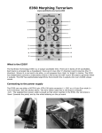
MOTM-420 Voltage-Controlled Filter
Assembly Instructions & Owner’s Manual
Synthesis Technology
6625 Quail Ridge Dr.
Fort Worth, TX 76180
(817) 281-7776
www.synthtech.com
July 26, 1999
MOTM-420 PARTS LIST
Please carefully check that all parts are in your kit. If you have a suspected shortage,
please call or email. If you get free extra stuff, keep it for next time.
Capacitor bag, containing the following 15 parts:
2ea 10mfd, 25V Electrolytic
C14, C15
1ea 3.3mfd, 50V non-polar Electrolytic
C5
1ea 33mfd, 35V low-leakage Electrolytic
C12
1ea 22pf (marked 220) ceramic axial
C13
2ea 2200pf axial polystyrene
C10, C11
1ea 1000pf yellow box (marked E102 or 1N)
C2
7ea 0.1mfd (marked 104) ceramic axial
C1, C3, C4, C6, C7, C8, C9
Resistor bag, containing the following 36 parts:
6ea 10K (brown, black, orange)
R17, 25, 26, 28, 29, R30
4ea 220 ohm (red, red, brown)
R23, 24, 27, R31
4ea 100K 1% (brown, black, black, orange) R1, R2, R3, R10
3ea 100K (brown, black, yellow)
R13, R20, R21
3ea 51K1 1% (green, brown, brown, red)
R11, 12, 19
2ea 8K2 (gray, red, red)
R8, R14
2ea 22K (red, red, orange)
R16, R32
1ea 1K 1% 3W tempco (large, black)
R4 (this mounts over Q1)
1ea 44K2 1% (yellow, yellow, red, red)
R5
1ea 475K 1% (yellow, violet, green, orange)
R6
1ea 4K7 (yellow, violet, red)
R7
1ea 221K 1% ( red, red, brown, orange)
R9
1ea 2K7 (red, violet, red)
R15
1ea 2K2 (red, red, red)
R18
1ea 75K (violet, green, orange)
R22
1ea 82K (gray, red, orange)
R33
1ea 12K (brown, red, orange)
R34
1ea 39K (orange, white, orange)
R35
1ea 510 ohms (green, brown, brown)
R36
IC bag, containing the following 12 parts:
1ea MXL1013CN8 precision op amp
1ea TL072 dual op amp
1ea JRC4558 dual op amp
1ea JRC4556 dual op amp
1ea LM13600AN dual OTA
1ea SSM2220 dual matched PNP
6ea 1N4148 diodes
SYNTHESIS TECHNOLOGY
MOTM-420 ASSEMBLY 6/25/99
WWW.SYNTHTECH.COM
U1
U2
U3
U4
U5
Q1
D1 – D6
PAGE 2
Misc #1 bag, containing the following 6 parts:
2ea Axial ferrite beads (plain, gray things)L1, L2
1ea MTA-156 power connector
JP1
1ea SPDT (ON-OFF-ON) toggle switch
SW1
1ea trimmer, 20K Bourns 3386P
TP1
1ea trimmer 2K Bourns 3386P
TP2
Knobs, 7ea, ALCO PKES90B1/4
Jacks, 7ea Switchcraft 112A
Pots, 7ea containing the following:
1ea 100K cermet Spectrol 149
3ea 100K conductive plastic Bourns 95A1
3ea 100K log conductive plastic Spectrol 148
VR7
VR1, 2, 3
VR4, 5, 6
Front panel
Mounting bracket
Wire bag, containing the following 12 wires:
4ea RG-174 coax, 4 ½ inches
1ea RG-174 coax, 7 inches
3ea 3-wire set 22ga, 6 1/2 inches (white/red/black)
2ea 2-wire set, 22ga, 7 inches (white/orange)
1ea 3-wire set, 22ga, 4 inches (white/orange/gray)
1ea Power Cable, 20”
Hardware bag, containing:
4ea #8-32 x 3/8 black screws (for mounting module to rack)
4ea #6-32 x 1/2 zinc screws (for attaching pc board to bracket)
4ea 1/4 inch aluminum spacers
6ea #6 KEPS nuts (2 for attaching bracket to front panel, 4 for pc board)
7ea small tie-wraps
9ea small heat-shrink tubing
Organic Solder
No-clean Solder
PC Board, MOTM-420
*** In addition, you will need a very small amount of silicone heat-sink
compound. Available from Allied, Newark, Mouser, Maplin, and many others ***
SYNTHESIS TECHNOLOGY
MOTM-420 ASSEMBLY 6/25/99
WWW.SYNTHTECH.COM
PAGE 3
GENERAL INFORMATION
Thank you for purchasing the MOTM-420 Voltage-Controlled Filter (VCF). If you have any
issues concerning the building or use of the kit, please contact us at (817) 281-7776 or by
email: [email protected]
This kit should take the average builder between 3 to 4 hours. The VCF kit contains many
different resistors and special parts. However, please remember this is NOT a speed
contest; it is an accuracy contest. There is no rule that you have to complete the entire kit
in one day (as long as you wash the flux off!).
Successful kit building relies on having the proper tools. Here is a list of what you will need
to build your MOTM-420:
*
*
*
*
*
*
*
*
*
*
*
*
*
Soldering iron, 50W max power
A heat-shrink gun. (optional, but highly recommended)
Needle-nose or chain-nose pliers
Diagonal cutters
Allen key set for securing the knobs (1/16” or 1.6mm)
Magnifying glass: to read the capacitor codes and to inspect solder joints
Lead bending tool (optional, but makes the job go much faster)
DVM (Digital Volt Meter) or oscilloscope (to check the output)
#1 Philips screwdriver
Small, flat screwdriver for adjusting the trimmers
Fingernail brush for washing off the organic flux
Old towel for blotting dry pc board
Heat-sink compound: this is REQUIRED for proper VCF operation. Available from
Allied, Newark, Mouser, Radio Shack, Farnell, and most all electronic supply
companies. (Postal regulations force us not to include with the kit!)
For more information of tools used and suggestions, see the MOTM FAQ and Tutorial pages
at http://www.synthtech.com.
You also may find it useful to purchase additional heat-shrink tubing (1/8” diameter, 2:1
shrink ratio) and solder. Just be sure it is NOT rosin-based flux!
HOW TO FOLLOW THE DIRECTIONS
Please read the entire instruction before proceeding. There may be valuable information at
next to it. After you
the end of the instruction. Each instruction has a check box
complete the instruction, check the box. This way you can keep track of where you are in
the process.
VERIFY THE PARTS LIST
Verify that all of the parts are in the kit as shown on the parts list.
SYNTHESIS TECHNOLOGY
MOTM-420 ASSEMBLY 6/25/99
WWW.SYNTHTECH.COM
PAGE 4
A WORD ON SOLDERING
There are 2 very different types of solder used in the kit. Most of the soldering uses
‘Organic Flux’ solder. This is strictly for use on the pc board, and is NOT to be used
on the front panel wiring!
In order for solder to ‘stick’ to the copper, a chemical called ‘flux’ is embedded in the solder.
The flux leaves a residue on the pc board that should be cleaned with warm water. DO NOT
USE SOAP OR OTHER CLEANSERS. Most of the parts in the kits are ‘waterproof’ and can
be washed in the sink. The flux is OSHA approved for flushing down the drain, so don’t
worry about that! A soft brush is used to gently scrub the board. We recommend a
‘fingernail brush’, which is about 1” x 2” and can be found for about $1.
The other type of solder is called ‘No Clean Flux’; because as the name implies it does, not
require washing. This solder is used for wiring the pots, switches, jacks, etc. This solder is
harder to use on the pc board; because even when melted, it is not very fluid (about the
consistency of toothpaste). We will use it VERY SPARINGLY on the pc board.
OK, let’s get started on the board!
PART #1: SOLDERING THE RESISTORS
Since there are more resistors than anything else, we will start here. If you do not know the
resistor color code, refer to the parts list. Resistors are not polarity sensitive, but the board
will be easier to debug (and look nicer) if you point the first color band in the same direction
for all the parts. The color code is also in the README FIRST document that every
customer receives with his or her first order.
There are 2 types of resistors in the MOTM-420 kit: standard 5%, 1/4W parts and special,
precision parts. The precision parts use a slightly different color-coding scheme. If you are
unsure of a resistor’s value, use your trusty DVM to measure it! Inserting the wrong
resistor in the VCF kit will cause interesting behavior! And, it’s very hard to find the error!
Lastly, the large black “tempco” resistor is the last part soldered on the pc board. DO NOT
solder it until told to do so!
You will start by soldering in ALL of the 5% resistors.
Find the RESISTOR bag.
Find the MOTM-420 blank pc board. There is a copy (larger than actual size) of the
silkscreen which shows where the parts go at the end of this document. It will be
useful if you locate the part on the print first, put the part in the board, then
‘check off’ the silkscreen. All parts are inserted from the side of the board with the
white silkscreen (the “top” side).
SYNTHESIS TECHNOLOGY
MOTM-420 ASSEMBLY 6/25/99
WWW.SYNTHTECH.COM
PAGE 5
We will stuff the resistors by value to make things easier. The resistors (and other
long-leaded parts) are inserted on a 0.4 inch spacing. The important thing is to be
sure that the part is sitting all the way down on the board. Push the leads in the
holes, push the part on the board, and then bend the leads on the bottom outwards
to a 45 degree angle (roughly!). This is called ‘cinching the leads’: and keeps the part
from falling out! From the bottom of the board, solder (using the organic flux),
applying heat to the pad for about a half second first, then applying just enough
solder to make a small puddle that looks like a tiny pyramid. Enough solder should
flow in the hole such that on the top (component) side, a small amount is on the top
pad as well
The rule of soldering: don’t use too much, you can always add more! Cut the leads
flush with the top of the solder joint with your diagonal cutters.
Locate the 100K resistors (3) and solder into R13 (near C5), R20, and R21 (above
R13).
Locate the 4K7 resistor and solder into R7 (above TP1).
Locate the 8K2 resistors (2) and solder into R8 (above R7) and R14 (by SW1).
Locate the 2K7 resistor and solder into R15.
Locate the 22K resistors (2) and solder into R16 and R32 (top right corner).
Locate the 10K resistors (6) and solder into R17 (bottom right corner), R25, R26,
R28, R29, and R30 (all are near U5).
Locate the 2K2 resistor and solder into R18 (below TP2).
Locate the 75K resistor and solder into R22 (by VR5).
Locate the 4 220 ohm resistors and solder into R23, R24, R27, and R31 (all by U5).
Locate the 82K resistor and solder into R33 (top right corner).
Locate the 12K resistor and solder into R34 (below R18).
Locate the 39K resistor and solder into R35.
Locate the 510 ohm resistor and solder into R36.
SYNTHESIS TECHNOLOGY
MOTM-420 ASSEMBLY 6/25/99
WWW.SYNTHTECH.COM
PAGE 6
PART #2: Precision Resistors EXCEPT R4
IMPORTANT NOTE! R4 is the last part soldered on the board! DO NOT SOLDER
this part until told so. You have been warned!
Locate the 4ea 100K, 1% resistors and solder into R1, R2, R3, and R10 (all near U1).
Locate the 44K2 1% resistor and solder into R5 (by TP1).
Locate the 475K 1% resistor and solder into R6 (above U2 and C3).
Locate the 221K 1% resistor and solder into R9.
Locate the 3ea 51K1 1% resistors and solder into R11, R12, and R19 (all by U1).
STOP! Save the big black tempco resistor for later. DON’T LOSE IT!
PART #3: BOARD WASH #1
Verify all the resistors are in the correct position.
Verify all the resistors are flat on the board. Correct if needed. Check solder joints.
Wash the board in warm water, gently scrubbing both sides.
Shake the board a couple of times, blot dry with an old towel (the leads will frazzle
a good towel). Let dry at least 15 minutes.
Take a little break! You are about 1/3rd of the way finished.
PART #4: CAPACITORS EXCEPT C10 & C11 (polystyrene)/Board Wash #2
Locate the CAPACITOR bag. Set the polystyrene 2200pf caps (the big silvery ones
with the long, thin leads) aside. THESE CAPS ARE SOLDERED IN AFTER THE
ICs!
Locate the 22pf cap and solder into C13 (between R35 & R36).
Locate the 1000pf yellow box cap and solder into C2 (next to U2).
Locate the 0.1M caps (7). Solder into C1, C3, C4, C6, C7, C8, and C9.
SYNTHESIS TECHNOLOGY
MOTM-420 ASSEMBLY 6/25/99
WWW.SYNTHTECH.COM
PAGE 7
Locate the 3M3 non-polar electrolytic cap. Solder into C5.
Locate the 33µfd cap. Note that it has a stripe on one side (the – terminal). Solder
into C12 with the stripe away from the + pad.
Locate the 10µfd electrolytics (2). Note that there is a stripe on the NEGATIVE
terminal. The pc board has a + on the POSITIVE terminal. Carefully stick the
capacitors into C14 and C15 with the stripe away from the + pad on the board.
Wash the board again, gently scrubbing both sides. Use ONLY warm water!
PART #5: MISC and IC STUFF
Almost done with the parts on the pc board! This will finish up the soldering with the
organic flux.
Locate the MISC #1 bag and the IC bag.
Locate the ferrite beads (2). They are axial parts, gray colored with no markings.
These are non-polar, and are soldered into L1 and L2 (by JP1).
Locate the MTA-156 power connector. Solder into JP1. Note that the connector has
a ‘locking tab’ on one side. This side is the “inside” facing relative to the pc board.
Note the silkscreen symbol for JP1 has a line on one side, indicating this is the side
where the locking tab goes.
Locate the MXL1013 op amp. Solder into U1. Note that Pin #1 is the
square pad. Pin #1 is the pin near the very small ‘dimple’ in the top of the part.
All of the ICs point “to the bottom” on the pc board.
Locate the TL072 op amp. Solder into U2.
Locate the JRC4558 op amp. Solder into U3.
Locate the JRC4556 op amp. Solder into U4.
Locate the LM13600AN OTA. Solder into U5.
Locate the SSM2220 (looks like an IC!). Solder into Q1, pointing down as the rest.
Locate the diodes (6). Note each has a dark band on one end on the body. This is the
cathode and it must be placed in the holes with the band pointing to the left. Solder
into D1 – D6.
SYNTHESIS TECHNOLOGY
MOTM-420 ASSEMBLY 6/25/99
WWW.SYNTHTECH.COM
PAGE 8
Locate the blue trimmer pot marked P 202 on it’s side. This is a 2K trimmer. Solder
into TP2.
Locate the trimmer pot marked P 203. This is a 20K trimmer. Solder into TP1.
Locate the 2ea 2200pf polystyrene caps. Solder into C10 and C11.
Being careful NOT to solder the 2 pads for R4, apply a small bit of solder to the via
holes. These are the small pads that allow traces to “change sides” of the pc board.
DO NOT SOLDER PADS FOR THE REMAINING COMPONENTS!!
PART #6: FINAL BOARD WASH & INSPECTION
Verify all the parts are in the correct locations. Make sure all of the ICs are pointing
the same direction and that all of the diodes point to the left.
Inspect the solder joints. Any solder shorts? Too much solder? Missing joints?
Wash the board under warm water. Scrub gently. Dry.
THIS IS A GOOD STOPPING PLACE TO REST OR PUT THE KIT AWAY UNTIL
LATER.
You are now finished with the Organic flux solder. All soldering past this point is
using the No-Clean solder. You do not have to wash the board anymore.
PART #7: FINISHING THE PCB
You will now solder in the remaining parts on the pcb in preparation for wiring to the front
panel. USE THE NO-CLEAN SOLDER. BE CAREFUL!
Locate the Spectrol pots (4). There are 3 marked 148-9609-104. These 3 pots are
soldered into VR4, VR5, and VR6. Be SURE the pots are sitting down all the way
flat on the pc board with the shafts sticking straight out, square to the board. Solder
the 100K linear pot (marked 149) into VR7.
Locate the Tempco resistor R4. This part is mounted in a special way: it goes on top of
transistor Q1! Why? In order to compensate for the temperature drift of Q1, the resistor
must be in good thermal contact. Refer to the illustration and be careful!
a) Apply a small amount of heat-sink compound to the top of Q1. Use just enough to cover
the entire top without dripping down over the sides.
b) Bend the leads of R4 about 1/8th inch away from the body, at a 90 degree angle.
c) Insert the resistor into the 2 holes: one to the top of Q1 and one to the bottom of Q1.
SYNTHESIS TECHNOLOGY
MOTM-420 ASSEMBLY 6/25/99
WWW.SYNTHTECH.COM
PAGE 9
d) Push R4 all the way down so that the bottom of the resistor is sitting on top of Q1. The
heat-sink compound will “squish out” from under R4. Wipe of any excess. WARNING!
This stuff is next to impossible to wash out of blue jeans!
e) Solder R4, making sure the resistor is level and TOUCHING Q1.
T E M P C O R E S IS T O R
S SM 2220
P C B O A R D [S ID E V IE W ]
Locate the 5 pieces of RG-174 black coax cable. Again, note that one end has
longer wires stripped than the other. The short ends will go in the pc board in
positions J1, J4 to J7. Look at the pc board. Notice that in the coax positions,
there is a large hole pad (lower pad) and a smaller pad (top hole). The braided wire
is soldered into the larger hole. The smaller, inner conductor goes in the top
hole. BE SURE THE SHORTER BRAIDED END GOES INTO THE PC BOARD.
The 1 LONG coax cable solders into J1 (1V/OCT IN). The 4 SHORT coax cables go
into J4 – J7. Solder each coax cable into the holes. Attach a tie-wrap to secure the
coax cable flush to the board. The tie-wrap goes down, into the left hole and up
through the right hole. Secure and trim off any excess.
Find the orange/white/gray twisted wire. This is soldered into SW1. Solder the
Orange wire into the top #1 hole, the White wire into the middle #2 hole, and the
gray wire into the bottom #3 hole.
Find the 2 long orange/white twisted pairs. They go into J2 and J3. Solder the
Orange wire into the RIGHT hole #2 and the White wire into the LEFT #1 hole.
Find the 3 red/black/white twisted wires. They go into VR1, VR2 and VR3. In all
cases, solder the White wire into the LEFT #1 hole, the Black wire into the MIDDLE
#2 hole, and the Red wire into the RIGHT #3 hole. Be sure you solder the shorter
conductor end into the pc board!
YOU ARE NOW FINISHED WITH THE PC BOARD WORK! BREAK TIME.
SYNTHESIS TECHNOLOGY
MOTM-420 ASSEMBLY 6/25/99
WWW.SYNTHTECH.COM
PAGE 10
PART #8: FRONT PANEL PREPARATION
You will now attach components to the front panel. It is HIGHLY recommended that you
use a set of hollow shaft nut drivers, NOT PLIERS, to tighten the nuts. This prevents
scratching. NOTE: all references to part orientation is from the REAR of the panel.
Locate the 7 Switchcraft jacks. Notice that from the rear, there is a beveled corner.
This corner is ALWAYS CONNECTED TO GROUND, USUALLY WITH THE
BRAIDED CONDUCTOR. Each jack has a flat washer, a lockwasher, and a ½” hex
nut. Remove the nuts and washers from each jack. Place aside. Keep the lockwasher
on the jacks.
Insert the 7 jacks/lockwashers, with the beveled corner in the upper right corner,
into the 7 holes. Place the flat washer on the jack, then the hex nut. Hold the jack
with one hand on the backside, keeping it ‘square’. Tighten the hex nut with a nut
driver. NOTE: when tight, not much of the exposed threads of the jack are exposed.
You are now ready to attach the pc board to the bracket and then wire up to the panel.
PART #9: ATTACH PC BOARD TO BRACKET/PANEL
In the HARDWARE bag, locate 4 #6-32 x 3/8 screws, 6 #6 KEPS nuts, and 4
spacers.
Locate the mounting bracket. The pc board attaches to the bracket, with the 4
screws threading from the top of the board, through the spacers, through the
bracket, and then out the bottom of the bracket. The #6 KEPS nut attaches on the
bottom of the bracket. Note the bracket has 2 long mounting flanges with a hole
in each. These attach to the 2 threaded studs sticking out of the rear of the panel.
The 4 pots each stick in its panel hole when the bracket is screwed down on the 2
threaded posts.
Attach the pc board to the bracket. The flanges will point upwards when the pc
board is sitting on the bracket. Note that the bracket holes for the pc board are
actually oblong. This is to allow adjustment for the pc board to firmly press
up against the back of the panel. As a start, set the 4 screws ALL THE WAY
TO THE LEFT of the oblong holes. Loosely tighten the 4 KEPS nuts on the
bottom.
THIS IS A VERY IMPORTANT STEP, SO PAY ATTENTION AND READ ALL OF
IT BEFORE PROCEEDING!
Note that each of the 4 pots on the pc board have 2 hex nuts and a flat washer.
Remove the first hex nut and the washer. Set aside.
What you will do now is adjust the remaining hex nuts so that when the bracket is
all the way down on the panel’s threaded studs, all the pot hex nuts touch the rear
SYNTHESIS TECHNOLOGY
MOTM-420 ASSEMBLY 6/25/99
WWW.SYNTHTECH.COM
PAGE 11
of the panel.
Screw (by hand) each hex nut on the pots so that it is all the way on (touching
the face of the pot). Now, pick up the pc board/bracket assembly and carefully
slide it over the 2 threaded studs, making sure the pots are aligned in the holes.
Use 2 #6 KEPS nuts and tighten the bracket to the panel.
Loosen the 4 KEPS nuts on the bottom of the bracket. Slide the pcb ALL THE WAY
TO THE RIGHT AS FAR AS IT WILL GO, so that the 4 pot nuts are all pressing
against the panel. By hand, put hex nuts on the outside threads of VR7 and VR6 to
keep the pc board in place. Now, tighten the 4 KEPS nuts on the bracket. The pcb
and bracket should be secure, with no gaps visible between the panel and the pot
nuts. You may need to loosen the nuts on the pots, so that they are touching
the back of the panel. Again, make sure each pot’s nut is touching the back of
the panel (no gaps!). There will be a gap from the edge of the pc board to the panel.
Remove the hex nuts on VR6 & VR7. For all of the pots, first put on the flat washer,
then the hex nut. Tighten with a ½” nut driver.
PART #10: FINISH WIRING TO THE PANEL
Please read the following instructions carefully. In order to neatly attach the many wires to
the front panel components, the wires are soldered in a specific order.
Find the SPDT toggle switch. These solder to the 3 wires in SW1 on the pc board. To
make things go easier, first you will solder the wires to the component, then attach
the component to the front panel. Solder the Gray wire to the TOP lug, the White
wire to the MIDDLE lug, and the Orange wire to the Bottom lug (it doesn’t matter
which outside lug you call ‘TOP’). Now, remove the outer hex nut. Place the switch
through the small hole labeled MODE with the Orange wire on the bottom, near
the phonejacks. Tighten the outside hex nut, but DO NOT OVERTIGHTEN!!
Locate the 3 blue Bourns 91A panel pots. These solder to the 3 wires in VR1, VR2,
and VR3. However, be careful because the ordering is different on the actual
panel!
Each pot is soldered the same way. Facing the rear of the pot, you will see tiny
indicators for each lug: 3 2 1 (lug #3 is to the left). First, slip a piece of the heatshrink tubing over the wire (you may need to un-twist some first). Bend the wire
into a small “J” shape and insert through the little slot in the lug. Solder the wire.
Repeat for the other 2 wires. When all three wires are soldered, slide the heat-shrink
over the lug/wire and apply heat (a heat-shrink gun is highly recommended).
Solder the wires in VR1 to a pot: the Red wire goes to the LEFT #3 lug, the Black
wire goes to the MIDDLE #2 lug, and the White wire goes to the RIGHT #1 lug (yes,
I realize the pcb numbers don’t match the pot numbers. Oh well……). Don’t forget
the heat-shrink goes on first.! When you are finished soldering and the tubing is
SYNTHESIS TECHNOLOGY
MOTM-420 ASSEMBLY 6/25/99
WWW.SYNTHTECH.COM
PAGE 12
shrunk on, insert the pot into the top panel hole (FREQ). Remove the outside hex
nut and flat washer. Place the pot in the hole with the 3 wires pointing down,
towards the jacks. Put the flat washer and hex nut back on the pot and tighten
with a ½” nut driver.
In the exact same manner, attach the VR3 wires to a panel pot. This time, be SURE
the pot goes into the second hole marked FM1. Secure to panel.
In yet again the same exact manner, attach the VR2 wires to the remaining panel
pot. This pot goes in the third hole marked FM2. The wires will “cross over” the FM1
wires. Secure to panel. Using a ty-wrap, bundle the 3 pot wires together.
Now you will solder to the 7 jacks. Each jack has 3 lugs: from the rear we will refer
to them as LEFT, TOP, and BEVELED. In all cases, there is nothing soldered to the
TOP lug.
Solder the AUDIO OUT coax in J7 to the OUT jack. For all coax connections to the
jacks, the braid goes to the BEVELED lug, and the inner conductor goes to the LEFT
lug.
Solder the IN 3 coax in J6 to the IN 3 jack.
Solder the IN 2 coax in J5 to the IN 2 jack.
Solder the IN 1 coax in J4 to the IN 1 jack.
Solder the orange/white wire in J2 to the FM2 jack. The white wire solders to the
LEFT lug, and the orange wire to the BEVELED lug.
Solder the orange/white wire in J3 to the FM 1 jack. White wire to LEFT, orange to
BEVELED.
Solder the 1V/OCT coax in J1 to the 1V/OCT jack. Use a ty-wrap to bundle the coax
together. Trim the excess.
Rotate all of the front panel pots fully counter-clockwise. Locate the KNOBS.
Notice each knob has a white line on it. Place the knob on the pot shaft,
align the white line to the ‘0’ tick mark, and tighten the hex screw. The silver
part of the knob has a protective clear plastic overlay that can be removed if
desired. Gently rub with your fingernail across it and it will peel off.
************************************************************************************
CONGRATULATIONS! YOU HAVE FINISHED BUILDING THE MOTM-420!
************************************************************************************
SYNTHESIS TECHNOLOGY
MOTM-420 ASSEMBLY 6/25/99
WWW.SYNTHTECH.COM
PAGE 13
All that’s left to do is test it! But before we do, please read the following Theory of
Operation.
THEORY OF OPERATION
The MOTM-420 VCF has 3 basic sections: a voltage summing amplifier for the control
voltages, an exponential voltage-to-current converter, and 2 current-controlled integrators
that form the actual filter.
INPUT VOLTAGE SUMMER
Refer to the schematic page marked M420.SCH for the following discussion.
The precision DC op amp U1 sums the various sources of control voltage to feed the
exponential converter. Op amp section U1A is an inverting summer. The 1V/OCT input is
summed at unity gain (set by the ratio R2/R10). The filter’s initial cutoff frequency is set by
panel pot VR1 and gain resistor R9 (if you want to reduce the “spread” of the filter’s range,
increase R9 to like 390K – 470K). The filter has a variable FM2 input that due to the 51K1
gain set resistor, can achieve approximately 0.5V/OCT.
A second inverting stage U1B is used because the “sense” of the PNP exponential converter
is such that positive control voltage inputs will increase the cutoff frequency.
We have added a special type of input circuit for FM1: it is called a reversing attenuator.
Resistors R12 and R19 are “in-between” the panel pot VR3. Note carefully R19 goes to the
input of the following inverter stage, while R12 goes back to the first stage. The reason is
explained below.
If the pot is rotated all the way to the left (CCW), the wiper (connected to the input jack J3)
is “all the way over” to the R19 side. Therefore, the voltage applied to J3 is split into to
paths: one path has a gain of ~2 (the R1/R19 path) and the other has a gain of ~0.66 (the
R2/(VR3 + R12) path). The net effect is of course (.66)(2) = 1.33
Therefore, the FM1 input can be set to control the filter from –0.75V/oct to +0.75V/oct. This
control range can be adjusted by changing R12 AND R19 (they both need to be 1% resistors
of the same value).
EXPONENTIAL CONVERTER
The voltage output of the summing amp U1B is divided by the ratio of R4/(R4+R5+TP1).
The reason is that the base-emitter junction of Q1A wants to see a 18.02mv change for each
1.00V change at the summer output. Also, the collector current of Q1 has a temperature
dependence. This temperature coefficient is cancelled by R4. That is why R4 and Q4 must
be in “thermal contact”: they need to be as close as possible to the same temperature.
So, the desired attenuation ratio is 1V in = .01802V out or ~55.5:1. That is why R5 + TP1
value is close to 54K if TP1 is in the middle. Clever, yes??
SYNTHESIS TECHNOLOGY
MOTM-420 ASSEMBLY 6/25/99
WWW.SYNTHTECH.COM
PAGE 14
Now we need a “reference current” for the VCF, which is what the current source supplies
with 0.0V out of the summer. This current is set by R6, and is 15V/475K or ~31.6uA (this
same topology is used in the MOTM-300 VCO). Q1B is a “current mirror” that actually
drives the 2 OTA stages. R7 & R8 are protection resistors, and C2 overdamps U2A (since it
is operating open-loop). The “idle” cutoff frequency is ~250Hz (the exact value is left as an
exercise for the reader).
FILTER SECTION
The filter is based on the Korg MS-20 circuitry. The MS-20 used a custom OTA gain stage,
and the MOTM-420 uses a LM13600AN OTA stage. “Vintage op amps” are used to
duplicate the sonic characteristics of the MS-20 filter.
OTA stands for Operational Transconductance Amplifier. The “gain” of the OTA is:
Iout = 19.2 * Vdiff * Icontrol
Where Vdiff is the differential voltage between the + and – input pins and Icontrol is a
control current fed into the ABI pin. So, an OTA has a Current Out/Voltage In transfer,
hence the term “transconductance” (note a ‘standard’ op-amp is Voltage Out/Voltage In).
As every good EE knows, the simplest low-pass filter is a series resistor and a cap to
ground. The “corner frequency” is the familiar:
F = 1/(2)(pi)RC
Since a variable C is hard to make, most filters use a variable R(esistance) to make a
variable filter. Now, the clever reader will also recall Ohm’s Law:
I = V/R
Which can be re-written
R = V/I
Hmmmm…..if an OTA has a I/V function, and since the R for our simple low-pass is in the
denominator (ie 1/R factor) AND since 1/R is I/V….HEY! the OTA is a variable resistor,
whose “value” is set by the control current Icontrol. We got ourselves a VCF!!
Note: the following discussion skips tons and tons of college-level calculus and complex
arithmetic. Sorry!
The MOTM-420 uses 2 filter sections: U5A + C10 and U5B + C11. These sections form the
variable “RC” sections of the filter. As stated earlier, the ‘R’ is really set by the control
current from the summing amp/exponential converter. The OTA’s output current is the
product of the audio signal (the Vdiff part) and the current into the ABI pins.
In order to “peak” the filter at the cutoff frequency (called Resonance), we take a portion of
the filter output and feed it back into the input. This is the function of U4A. Panel pot VR7
SYNTHESIS TECHNOLOGY
MOTM-420 ASSEMBLY 6/25/99
WWW.SYNTHTECH.COM
PAGE 15
is a simple voltage divider. U4A is a non-inverting amp whose gain is set by the
combination of R18 and trim pot TP2 (the MAX Q trim). R32 is a ‘trick’ to get a log-like
response from linear pot VR7.
The 6 diodes across the opamp is a voltage limiter. Each diode has a 0.6V drop, so 3 diodes
in series is a ~1.8V limiter.
The 3 audio inputs are summed by U3A. The individual gains for each stage is 75K/100K or
0.75. Since we have 3 inputs, and each can be connected to say a VCO output at +-5V pk-pk,
the input summer will start to clip at some point. This is just a compromise between pot
settings on the front panel versus all 3 inputs going full blast. You can adjust R22 up or
down in value to suit.
The filter output is amplified by U4B. It’s gain is 39K/12K or about 3.25. Therefore, the
“end-to-end” gain on a single signal is (.75)(3.25) = 2.4 which duplicates the MS-20
characteristic.
Note that the MOTM-420 can be used with ANY input levels, not just the +-5V pk-pk
“standard” MOTM levels. This makes the MOTM-420 ideal for processing just about any
audio signal in your studio!
The filter sections can be switched to form a lowpass filter, a highpass filter, or a notch
filter. Switch SW1 does this by selectively grounding audio signals to the 2 filter sections.
The theory behind this is beyond the scope of this discussion (entire books have been
written on this subject. I like “Analog Filter Design” by M.E. Van Valkenburg).
PRELIMINARY CHECK-OUT & CALIBRATION
The VCF needs two adjustments: the 1V/Oct tracking and the maximum Q trim.
Both of these trims are done “by ear”, so an oscilloscope is not required. However, hours of
enjoyment can be had watching the VCF output waveforms.
SETTING THE MAX Q TRIMMER
The MAX Q TRIM sets the point on the dial for the RESONANCE pot that causes the filter
to self-oscillate.
a) a suggested point on the dial for self-oscillation is the ‘8’ or ‘9’ tick mark. Set the RES
pot to the desired point on the dial.
b) Set the MODE switch to LP
c) Set the FREQ knob to 5 (straight up)
d) Plug an audio mixer or preamp into the OUT jack. Be sure your amp is not set too loud!
The ‘420 can pop a tweeter without any problems. Apply NO audio inputs to the ‘420.
e) Apply power to the ‘420. Slowly adjust the trimmer until you hear the filter oscillate.
The waveform is very close to a sine wave (it’s not perfect due to the capacitors not
being the exact same value and the OTA’s current outputs not exactly the same).
SYNTHESIS TECHNOLOGY
MOTM-420 ASSEMBLY 6/25/99
WWW.SYNTHTECH.COM
PAGE 16
SETTING THE 1V/OCT TRIMMER
First, apply power to the VCF and wait for 10 minutes. This allows the Q1/R4 temperature
to stabilize to operating point.
Although the purpose of the trimmer is to set the filter’s cutoff frequency to double for each
volt applied (ie 1V = 200Hz, 2V = 400Hz, 3V = 800Hz, etc) the easiest way is to set this is
use the VCF as a VCO!
From the above MAX Q procedure, the VCF will oscillate and act as a VCO over a limited
range of control voltage. This is because the exponential converter is not as precise as those
in VCOs (although the MOTM-420’s exponential converter is better than any VCF ever
made!).
The best way is to “beat” the output of the VCF with a VCO or synth that is in tune. Or, if
you have good pitch you can just set it by ear!
a)
b)
c)
d)
e)
plug a source of accurate 1V/OCT into the jack (ie a Kenton Pro-2000)
set the MODE switch on LP
set the FREQ to about 6
set the RES to 9.
Set the 1V/OCT ADJUST pot to the center position.
You should now be able to play the VCF as a VCO. Now adjust the trimmer for the best
tracking. The tracking is not that great, but over a 3-4 octave range you should get fairly
close. Remember, the exact cutoff frequency is not that important as it is for a VCO!
TROUBLESHOOTING
If your MOTM-420 does not work, please verify ALL of the following before contacting us.
The following reference directions assume that you are looking at the pc board with the
panel to the right and the power connector to the left.
All of the ICs are pointing the same way and all notches are ‘down’.
All of the diode’s bands are to the “left”.
The braided wire on the coax goes to the beveled side of the jacks.
The parts in the the right places, and the panel pots/switch is wired correctly.
No solder shorts or missing joints. BE SURE to carefully examine the pins on Q1 for
solder shorts.
SYNTHESIS TECHNOLOGY
MOTM-420 ASSEMBLY 6/25/99
WWW.SYNTHTECH.COM
PAGE 17
USE OF THE MOTM-420 VCF
The MOTM-420 is a “stand alone” module that can be used for filtering just about any
audio source (you can’t plug a guitar or mic directly into it, but use a ‘direct box’ or preamp
first!).
The important thing to remember is the top row of jacks is for control voltages, and the
bottom row is for audio inputs. You can use audio signals to modulate the filter.
The filter has three modes: LP (low-pass), HP (high-pass) and NF (Notch filter).
A low-pass filter is like a BASS tone control. It passes lower frequency and attenuates
higher frequencies. The point where this starts is called the cutoff frequency. Frequencies
below the cutoff “pass through” , while frequencies above cutoff get reduced in volume.
A hi-pass filter is like a TREBLE control: again higher frequencies “pass through” and
lower frequencies are attenuated.
A notch filter has a ‘dip’ at the cutoff frequency: if the signal is above OR below cutoff, it
passes through. At the cutoff frequency, it is attenuated.
Note that as a “side effect”, the phase of the output signal gets shifted relative to the input.
This can also add new sounds!
FILTER SLOPES AND RESONANCE
The amount the frequencies get attenuated relative to the cutoff is called the filter’s slope.
The MOTM-420 in LP and HP modes have a 12dB/oct slope (12dB is about 1/4th). For
example: if the LP filter has a 500Hz cutoff, a 1Khz sine wave is attenuated 12dB at 1Khz,
24dB at 2Khz, etc. The Notch filter, due to the circuitry used, has only a 6dB/oct slope. If
you are in NF mode, and the filter is set to 500Hz, then a 500Hz sine wave is attenuated
6dB at 500Hz (about half). Note these are ‘ideal’ figures and the actual filter will have
slightly less attenuation.
You can get “sharper” slopes by daisy-chaining MOTM-420s. If you have 2, then take the
OUT of the first one into the IN 1 of the second one. If both filters are set to the same
FREQ, RES, and MODE settings, the slopes will be twice normal (24dB/oct for LP/HP and
12dB/oct for Notch).
A popular filter effect is to add resonance to the cutoff frequency. Resonance is just adding
additional gain right at the cutoff frequency. The effect is that the filter sounds “brighter”
or “squeakier”. If you add too much resonance, the filter will self-oscillate.
SYNTHESIS TECHNOLOGY
MOTM-420 ASSEMBLY 6/25/99
WWW.SYNTHTECH.COM
PAGE 18
USING YOUR MOTM-420 WITH OTHER MOTM MODULES
1) The basic patch
The most basic synth patch is as follows:
a)
b)
c)
d)
VCO outputs into the filter IN jacks
Keyboard voltage into the 1V/OCT jack
MOTM-800 EG + output into the FM1 jack
OUT of the ‘420 into a mixer/amplifier
90% of synth sounds are tweaking this one set-up (can you say Minimoog??!?) Set MODE to
LP, set RES to 4, and start turning up the FREQ. Adjusting the FM1 pot set the amout of
filter “sweep”, and with the reversing feature you can sweep “up” or “down”!
Experiment with different VCO waveforms, adding noise, and filtering the output of a
MOTM-120.
2) Using 2 MOTM-420s
You can get very complex and interesting sounds by using 2 MOTM-420s.
a) Sweep one filter up while the other sweeps down. This is effective in NF mode to get
phasing effects. Use a LFO (or MOTM-300 in low-speed) and the FM1 pots to set the
relative sweeps. Use 2 different sweep rates to get even more lush effects (this is the
basic premise used in the MOTM-410 filter)
b) Emulate the MS-20 by setting one filter to HP and one to LP
c) Audio inputs plugging into the first filter will get attenuated differently that audio
inputs plugging into the second filter! This can make for some bizarre stuff.
d) You DO NOT have to use the keyboard CV into the filters. You can use FM1 or FM2
instead to have “variable tracking” (the Minimoog has switched tracking intervals). The
net effect of not tracking is the timbre will change as you play up and down the
keyboard. This may be a good thing!
USING THE MOTM-420 WITH OTHER GEAR
You can patch into the audio inputs from just about anything. The only thing to remember
is the "end-to-end” gain (at zero resonance) is about 2.4X. Of course, this is with the IN pot
at 10. The built-in audio mixer of the ‘420 comes in very handy for adjusting gains.
Unlike other MOTM modules, there is no real “minimum” voltage input requirement. The
limiting factor is the noise floor of the op amps. These op amps used in the ‘420 are older
bipolar types and not as “clean” as the OP-275s used in other modules. Why are they there?
To get that MS-20 sound!
Experiment! You can spend hour and hours playing with all the possible setting and audio
inputs.
SYNTHESIS TECHNOLOGY
MOTM-420 ASSEMBLY 6/25/99
WWW.SYNTHTECH.COM
PAGE 19
SPECIFICATIONS
MOTM-420 Voltage-Controlled Filter
Control Voltage input levels
-13V to +13V
Cutoff frequency range
1Hz to 28Khz
Output impedance
1000 ohms, nom.
Filter modes
LP and HP @ 12dB/oct, Notch @6dB/oct
Audio input level
50mv pk-pk min, 12V pk-pk max
Filter gain
2.4 nominal @ RES = 0, Input level @ 10
CONTROLS
FREQ
sets VCF initial cutoff frequency
RES
resonance (gain) at filter cutoff
FM1
level set for FM1 control voltage
FM2
level set for FM2 control voltage
IN 1, 2, 3
level set for audio input IN 1, 2, 3
MODE
selects filter mode (HP, LP, NF)
GENERAL
Power Supply
-15VDC @ 18 ma
+15VDC @ 18 ma
Size
2U x 5U
3.47” x 8.72”
88.1mm x 221.5mm
Depth behind panel
4.375 inches (111mm)
SYNTHESIS TECHNOLOGY
MOTM-420 ASSEMBLY 6/25/99
WWW.SYNTHTECH.COM
PAGE 20
IN 3
IN 2
IN 1
PHONEJACK
J6
PHONEJACK
J5
PHONEJACK
J4
1
2
3
4
JP1
VR6
100K
LOG
VR5
100K
LOG
VR4
100K
LOG
100K
R13
100K
R20
L1
FERRITE
L2
FERRITE
3M3
NP
C4
+15V
0.1M
3
2
C6
0.1M
+15V
-15V
C15
10M
25V
8
4
U3A
NJR4558
1
0.1M
C14
10M
25V
8
4
-15V
75K
VR3
100K
3
2
C1
R12
51K1 1%
R22
C5
R11
51K1 1%
VR2
100K
R10
100K 1%
100K
-15V
R2
100K 1%
R9
221K 1%
R21
PHONEJACK
J3
PHONEJACK
J2
PHONEJACK
MTA-156
FM1
FM2
1V/OCT
J1
INITIAL
FREQ.
VR1
100K
+15V
1
22K
R16
8K2
R14
51K1 1%
R19
+15V
U1A
MXL1013
6
5
LP 3
NF
HP 1
100K 1%
R3
4
8
SPDT
SW1
2K7
R15
R1
7
8
C7
R24
220
U1B
MXL1013
7
0.1M
U3B
NJR4558
2
R23
220
5
6
4
-15V
100K 1%
R5
-15V
4
2
3
IN-
LD
IN+
TP1
20K TP
10K
R25
6
V
-
V
+
8
7
5
1
-15V
0.1M
C9
BO
BI
OA
ABI
U5A
LM13600-A
1
1
+15V
0.1M
C8
44K2 1%
R26
10K
R6
475K 1%
C10
2200PF
POLY
R4
1K 1%
TEMPCO
-15V
1N4148
D4
3
2
1
4
1N4148
D5
1N4148
D2
10K
R17
8
+15V
R27
220
13
15
14
8
4
-15V
+15V
-15V
1N4148
D1
R31
220
10K
R30
C2
1
3
Q1A
SSM2220
2
3
10K
1N4148
D6
1N4148
D3
BO
BI
OA
ABI
R28
U4A
NJM4556
IN-
LD
IN+
U5B
LM13600-B
1
U2A
TL072
2
0.001M
9
10
12
16
8
6
2K2
R18
-15V
R7
4K7
-15V
TP2
2K TP
3386P
MAX Q TRIM
R29
10K
C11
2200PF
POLY
R8
8K2
Q1B
SSM2220
7
C3
0.1M
7
U2B
TL072
8
4
7
U4B
NJM4556
SYNTHESIS TECHNOLOGY
5
6
22PF
C13
39K
R35
PHONEJACK
J7
RESONANCE
VR7
100K
R33
82K
12K
R34
4
8
R36
510
6625 QUAIL RIDGE DR.
FORT WORTH, TX
76180
(888)818-MOTM
Title
MOTM 420 - VOLTAGE CONTROLLED FILTER
Size Document Number
C
M420
Date:
June 23, 1999 Sheet
1 of
22K
R32
33M
35V
C12
OUT
6
5
REV
A
1


