1
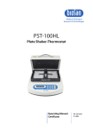
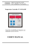
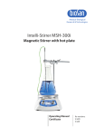
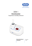
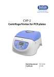
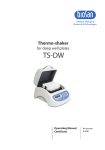
Medical–Biological
Research & Technologies
ES-20
Orbital Shaker-Incubator
Operating Manual
Certificate
for versions:
V.2AD
V.2AE
Contents
1. Safety Precautions
2. General Information
3. Getting Started
4. Operation
5. Specifications
6. Maintenance
7. Warranty and Claims
8. Declaration of Conformity
Page 3
1. Safety Precautions
The following symbols mean:
Caution! Make sure you have fully read and understood the present Manual
before using the equipment. Please pay special attention to
sections marked by this symbol.
GENERAL SAFETY
·
Use only as specified in the operating manual provided.
·
The unit should be saved from shocks and falling.
·
The unit must be stored and transported only in a horizontal position
(see marking on the package).
·
After transportation or storage keep the unit under room temperature for 2-3hrs
before connecting it to the electric circuit.
·
Use only cleaning and decontamination methods recommended by the
manufacturer.
·
Do not make modifications in design of the unit.
ELECTRICAL SAFETY
·
Connect only to electric circuit with voltage corresponding to that on the serial
number label.
·
Ensure that the electric circuit switch and the plug are easily accessible during
use.
·
Disconnect the unit from the electric circuit before moving.
·
Disconnect the power cord plug from power socket to turn off the unit.
·
After moving the unit check the shaker control cable connections.
·
Do not plug the unit into an ungrounded power socket, and do not use an
ungrounded extension lead.
·
If liquid penetrates into the unit, disconnect it from the electric circuit and have it
checked by a repair and maintenance technician.
DURING OPERATION
·
Do not impede the platform motion.
Page 4
·
Do not operate the unit in premises with aggressive or explosive chemical
mixtures.
·
Do not disconnect the shaker control cable when the unit is switched on.
·
Do not operate the unit if it is faulty or has been installed incorrectly.
·
Do not use outside laboratory rooms.
·
Do not place a load exceeding the maximum load value mentioned in the
Specifications section of this Manual.
BIOLOGICAL SAFETY
·
It is the user's responsibility to carry out appropriate decontamination if
hazardous material is spilt on or penetrates into the equipment.
Page 5
2. General Information
The ES-20 is a compact desktop Orbital Shaker-Incubator used for mixing of
biological liquids as well as for the incubation and cultivation of biological liquids
according to the program set by the operator.
Built-in microprocessor thermocontroller provides constant temperature control in
the incubator chamber and allows you to set and maintain the temperature inside the
incubator from 5°C above ambient. Forced heated air circulation inside the
transparent plexiglass chamber guarantees even temperature distribution.
Dismountable construction makes transportation easy.
Orbital shaking is controlled by the digital tachometer (rpm) and digital timer
regardless of the temperature. The unit is equipped with the direct-drive system
ensuring most reliable stable long-time operation (up to 30 days non-stop mixing).
The ES-20 is easy to operate. The two-line LCD display shows both set and actual
values for temperature, time and speed.
The device consists of thermal regulation and control block, shaking block and a
plexiglass chamber.
The following elements are located on the front panel:
- power switch (fig.1/1);
- display (fig.1/2);
- control buttons (fig.1/3).
The following elements are located on the rear panel:
shaking block control cable (fig.1/4);
socket for connecting the power cord (fig.1/5);
fuse holder (fig.1/6).
Five interchangeable platform types allow using the shaker for:
- growing cell cultures in flasks and other laboratory glassware;
- extracting tissue samples at physiological temperatures;
- other sample preparation processes.
The device is applicable in all the areas of medicine, biotechnology and
microbiology laboratory research.
4
2
3
1
5
6
Fig.1 Unit construction
Page 6
3. Getting started
3.1. Unpacking. Remove packing materials carefully and retain them for future
shipment or storage of the unit.
Examine the unit carefully for any damage incurred during transit. The warranty
does not cover in-transit damage.
3.2. Complete set. Package contents:
Standard set
- ES-20 Orbital Shaker-Incubator............................................................1 piece
- spare fuse (inside fuse holder) ...............................................................1 piece
- power cord.............................................................................................1 piece
- control cable ..........................................................................................1 piece
- Operating Manual; Certificate ................................................................1 copy
- ES-20 Orbital Shaker-Incubator Assembling instruction..........................1 copy
Optional accessories
- UP-12 platform u
.................................................................................on order
- PP-4 platform v
...................................................................................on order
- P-12/100 platform w
............................................................................on order
- P-6/250 platform x
..............................................................................on order
- P-16/88 platform y
..............................................................................on order
- HB-200 holder z
..................................................................................on order
u
UP-12
x
P-6/250
v
PP-4
y
P-16/88
w
P-12/100
z
HB-200
3.3. Set up:
- assemble the unit using the enclosed ES-20 Orbital Incubator Shaker
Assembling Instruction as a guide;
- place the unit on the horizontal even working surface;
- remove protective film from the display;
- connect the shaker control cable (fig.1/4) into the corresponding sockets on the
rear of thermostatic and shaking blocks;
- Plug the mains cable into the socket on the rear (fig.1/5) and position the unit so
that there is easy access to the power switch and connector.
Page 7
3.4. Platform installation:
- Install the platform by inserting the pins on the bottom side of the platform into
the holes on the supporting platform on the shaker.
Note! Move the unit carefully and only in vertical position.
4. Operation
4.1. Connect the unit to a grounded power socket. Set the Power switch to position I
(ON).
4.2. The display will turn on with the upper line (set p.) showing the previously set time,
speed and temperature and the lower line (actual p.) showing current readings of
the same parameters (STOP - time, 000 - rpm, incubator temperature °C, which
automatically starts rising according to the temperature set in the upper line).
Setting the parameters
Use the readings in the upper line of the display (set p.), while setting the
parameters required.
Setting time (Time)
4.3. Using the ▲ and ▼ Time keys (Fig. 2/1) set the required working time interval in
hours and minutes (increment - 1 min). Pressing the key for more than 3 sec will
increase the increment.
4.4.
4.5.
Setting speed (RPM)
Using the ▲ and ▼ RPM keys (Fig. 2/2) set the required shaking speed
(increment 10 RPM). Pressing the key for more than 3 sec will increase the
increment.
Setting temperature(Temp.ºC)
Using the ▲ and ▼ Temp. keys (Fig. 2/3) set the required temperature
(increment 0.1ºC). Pressing the key for more than 3 sec will increase the
increment.
1
2
PROCEEDING PARAMETERS
3
4
SET PARAMETERS
Shaker
Set p.
Actual p.
00:25
STOP
160
000
+37.0
+37.0
Time (hr : min)
RPM
Temp. °C
Time
RPM
Fig.2 Control panel
Page 8
Temp. Run/Stop
Timer
5
Caution! The chamber heating can be turned off only by setting the temperature
value below 25 °C (the display will show OFF - Temp.ºC - Set p.).
The set parameters can also be changed during operation.
Program execution
4.6. Place samples on the platform.
4.7. Press the Shaker-Run/Stop key (Fig. 2/4). The platform will start rotating and the
timer indicator will start counting up the time interval (with 1 min precision).
Note! If the rotation speed is set to zero, pressing Shaker-Run/Stop key starts the
timer but the platform does not move.
4.8. After finishing the program (after the set time elapses) the platform motion will stop
and the timer will be showing the flashing reading STOP accompanied by the
repetitive sound signal until the Shaker-Run/Stop key is pressed.
Caution! At the end of the set time period the platform movement is stopped
automatically, but the heating can be stopped ONLY manually by reducing the
temperature using the q
Temp. key (Fig. 2/3 - the lower key) till the OFF sign
appears in the upper line of the display.
4.9. If the working time is not set (the timer indicator in the upper line shows 00:00),
pressing the Shaker-Run/Stop key will start continuous operationof the unit (with
countdown timer in the lower line and indication OFF in the upper line) until the
Shaker-Run/Stop key is pressed again.
4.10. The timer can be reset during operation if required. Press theTimer-Run/Stop
key twice (Fig. 2/5) (first – to stop the timer, second – to restart the timer).
4.11. The platform motion can be stopped at any time by pressing the ShakerRun/Stop key. In this case the program realisation and the platform motion will
stop and the timer will switch into the STOP mode saving previously set time.
Press the Shaker-Run/Stop key to repeat the operation with the same time and
speed.
4.12. After finishing the operation set the power switch, located on the rear panel of the
unit, in position O (Off) and disconnect the external power supply with from
electric circuit.
Page 9
5. Specifications
The unit is designed for operation in cold rooms, incubators and closed laboratory
rooms at ambient temperature from +4°C to +40°C and maximum relative humidity
80% for temperatures up to 31°C decreasing linearly to 50% relative humidity at 40°C.
5.1. Temperature setting range .......................................................+25°C ... + 42°C
5.2. Temperature control range .................................5°C above ambient ... + 42°C*
5.3. Temperature setting resolution ..................................................................0.1ºC
5.4. Speed control range ........................................50–250 rpm (increment 10 rpm)
5.5. Maximum load...........................................................................................2.5 kg
5.6. Orbit ........................................................................................................10 mm
5.7. Digital time setting...........................................1 min – 96 hrs (increment 1 min)
5.8. Continuous operating time, not more ....................................................30 days
Recommended interval between operation sessions not less than 8 hours
5.9. Display .....................................................................................2x16 signs, LCD
5.10. Dimensions of the inner chamber .......................................305x260x250 mm
5.11. Dimensions ..........................................................................340x340x435 mm
5.12. Current/power consumption ......230 V, 0.7 A / 160 W or 120 V, 1.6 A / 170 W
5.13.Voltage ......................................................230 V, 50/60 Hz or 120 V, 50/60 Hz
5.14. Weight** ................................................................................................13.2 kg
* In cold room the unit provides stable thermostatic temperature control up to 30°C
above room temperature.
** Accurate within ±10%.
Optional
accessories
Description
Catalogue number
PP-4
Metallic flat platform with non-slip rubber
mat. Working dimensions 215 x 215 mm
BS-010108-BK
UP-12
Universal platform with adjustable bars for
different types of flasks, with non-slip rubber
mat. Working dimensions 265 x 185 mm
Additional holder for UP-12
BS-010108-AK
HB-200
P-12/100
P-6/250
P-16/88
Platform with clamps for flasks,
100 ml (12 places) Working dimensions
250 x 190 mm
Platform with clamps for flasks, 250 ml
(6 places) Working dimensions
250 x 190 mm
Platform with spring holders for
up to 88 tubes up to 30 mm diameter
(e. g. 10 ml, 15 ml, 50 ml tubes)
Working dimensions 275 x 205 x 75 mm
BS-010108-FK
BS-010108-EK
BS-010108-DK
BS-010116-BK
Biosan is committed to a continuous programme of improvement and reserves the
right to alter design and specifications of the equipment without additional notice.
Page 10
6. Maintenance
6.1. If the unit requires maintenance, disconnect the unit from the electric circuit and
contact Biosan or your local Biosan representative.
6.2. All maintenance and repair operations must be performed only by qualified and
specially trained personnel.
6.3. Cleaning and Care
The door and side panels are made of organic glass (poly methyl methacrylate
Plexiglass®) and are prone to scuffing and scratches if improperly cleaned. Care
during cleaning of the door and side panels is recommended to reduce wear of the
Plexiglass surface.
Caution! Clean the door and side panels with a mild detergent; never use organic
based compounds, pure alcohol, alcohol-containing cleaners (more than 15 %) or
Ammonia containing cleaners for Plexiglass! Do not use abrasive pads or
cleansers.
For decontamination, it is recommended to use a special DNA/RNA removing
solution (e.g. DNA-Exitus PlusTM, RNase-Exitus PlusTM).
The table below shows the interreaction of Plexiglass with ethyl alcohol and other
solutions.
Liquid
DNA-Exitus PlusTM
RNase-Exitus PlusTM
Ethyl alcohol 10-15 %
Ethyl alcohol 30 %
Ethyl alcohol Pure
H2O2 6%
Interreaction with Plexiglass
No reaction.
No reaction.
No reaction.
Limited reaction.
Full reaction. Do not use!
No reaction.
Standard ethanol (75%) or other cleaning agents recommended for cleaning and
decontamination of the stainless steel surfaces.
6.4. Fuse replacement
Disconnect the unit from the mains. Disconnect the power cable from the socket on
the rear of the shaker-incubator. Open the fuse holder (fig.1/6). Replace with the
correct fuse (for 230 V, - T1 A, for 120 V - T2 A).
Page 11
7. Warranty and Claims
7.1. The Manufacturer guarantees the compliance of the unit with the requirements of
Specifications, provided the Customer follows the operation, storage and
transportation instructions.
7.2. The warranted service life of the unit from the date of its delivery to the Customer
is 24 months. Contact your local distributor to check availability of extended
warranty.
7.3. If any manufacturing defects are discovered by the Customer, an unsatisfactory
equipment claim shall be compiled, certified and sent to the local distributor
address. Please visit www.biosan.lv, Technical support section to obtain the
claim form.
7.4. The following information will be required in the event that warranty or postwarranty service comes necessary. Complete the table below and retain for your
records.
Model
Serial number
Date of sale
Page 12
ES-20 Orbital Shaker-Incubator
8. Declaration of Conformity
Page 13
Version 2.04 – September 2013