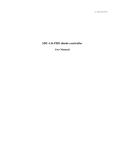
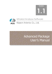
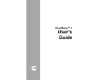
1
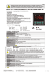
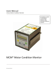
Industrial electronic systems
VEMA
Bulgaria, Pleven 5800, 27 Osogovo str.
tel./fax: +359/64/870172, tel.: +359/64/870170
e-mail: [email protected]
http://vema-bg.com
Temperature Controller TC 103 RAMP
SV
PV
TC103RAMP
Thermocontroller with auto-tuning of the PID-parameters to the
controlled object and option for gradually reaching the set value
(ramp function) using dynamical bias feature
USER’S MANUAL
I. INTRODUCTION
The microprocessor Temperature Controllers TC103RAMP-J/K/R/P offer optimal comfort
of service and visualization of information.
The Temperature Controllers TC103RAMP-J(/K/R) are assigned to work with thermocouples of type J, K or R, the TC103RAMP-P Temperature Controllers - with thermistors of
type Pt100.
The output signal is given either as a relay or a direct current output.
The Controller can be used as a 2-position on-off regulator if the alarm relay is used to
control the heater (cooler) instead of the control output.
The auto-tuning algorithm explores the parameters of the object to be controlled and sets the
corresponding PID-constants of the Controller.
The Controller is supplied with an alarm relay output for preventing the temperature from
great detours in the technological mode of the controlled object. The alarm relay output can
work in 16 programmable modes, non-latch standby sequence included.
The desired temperature SV (Set Value) and the current temperature PV (Process Value) are
constantly displayed.
The processes of heating, ramping and alarm are indicated by separate light diodes.
All parameters of the Controller can be set (changed) in Program Mode. In this case the
mnemonics of the parameters are shown on the "SV" display and the current values of the
parameters are shown on the "PV" display. Using the arrow buttons "<<" and ">>", the
parameters' values can be changed by one unit or at a faster rate (when the button is held
pressed for a longer time). The values of the parameters are automatically restricted within
their possible limits.
II. TECHNICAL FEATURES
1. Range of regulation of temperature:
2. Accuracy:
3. Ranges of parameters:
- gain factor Xp:
- differential constant time Td:
- integral constant time Ti:
- length of cycle Tc
- alarm limits tAL:
4. Indication:
-2-
-99°C to 450 °C
0.2 to 1 %
0 to100 %
0 to 250 sec.
0 to 999 sec.
0 to 200 sec.
-99°C to 450 °C
seven-segment, height 14.2 mm
5. Control output:
- relay type:
- open collector type:
- direct current:
6. Supply voltage:
7. Size:
8. Ambient temperature:
max. 250 V/2A, cosF=1
0/18V up to 30 mА
up to 20 mА
187 to 242 V at 48/62 Hz
96x96x85 mm
0 to 50 °C
III. MNEMONICS OF THE PARAMETERS
1. SSP - set temperature (SV) in static(=no ramp) mode
2. rSP - ramp endpoint
3. r n - ramp time (in minutes) for the SV to gradually change from SSP to rSP
4. r S - ramp time (in seconds) for the SV to gradually change from SSP to rSP
5. r t - pause time before ramp start
6. r i - start value of the bias (in percent)
7. r d -acceleration rate of the bias (in percent for thousand seconds)
8. r– - ramp toggle. Changing the value of this parameter will start/stop ramping
9. r P - Xp factor for PID in ramp
10. S P - Xp factor for PID in static mode
11. rtd - the differential constant for PID in ramp
12. Std - the differential constant for PID in static mode
13. rti - the integral constant for PID in ramp
14. Sti - the integral constant for PID in static mode
15. rtc - the length of cycle in ramp
16. Stc - the length of cycle in static time
17. ALL - lower alarm limit of temperature
18. ALU - upper alarm limit of temperature
19. ALn - number (type) of an alarm mode (0 to 15):
ALL
ALU
0 - no alarm output;
1 - the alarm zone is under ALL:
2 - the alarm zone is above ALU:
3 - under ALL and above ALU:
4 to 7 - same as types 0 to 3, however the alarm output is inverted;
8 to 15 - same as types 0 to 7 but with a non-latch standby sequence. The
standby sequence is initiated upon startup of the Controller or end of Program Mode, and
finished at the first occurrence of a non-alarm zone. During the standby sequence the SV
display is blinking and the alarm output works as if in a non-alarm zone, i.e. the alarm
output is off for types 8-11 and on for types 12-15.
-3-
IV. PROGRAM, MONITOR AND AUTO-TUNING MODES
Program Mode is switched on by pressing the "F" button. The display reads "SSP xxx",
where xxx is the Set Value of the temperature. Now the first parameter (Set Value) can be
changed using the arrow buttons "<<" and ">>". To save the new value and go back to
Monitor Mode, press (8 ). To get to any parameter in Program Mode, keep pressing (or hold
pressed) the "F" button until the mnemonics of the parameter shows up on the "SV" display.
Simultaneously pressing of both arrow buttons while in Monitor Mode will invoke the Autotuning Mode (s. CHARACTERISTICS) of the Controller. The display reads "OPt xxx",
where xxx is the current temperature and the "OPt" is blinking. In any other mode, pressing
both arrows will put the Controller back into Monitor Mode.
In Monitor Mode, the display reads the desired temperature (Set Value) and the current
temperature (Process Value). Blinking of "SV" indicator means that the standby sequence (s.
CHARACTERISTICS) is on, i.e. the Controller has not reached a non-alarm zone yet. In
Monitor Mode are displayed all possible errors:
- "EPr Err", if the EEPROM chip is damaged, or is just replaced;
- "xxx oFF", if the thermocouple is loose.
V. SPECIFIC CHARACTERISTICS
5.1. Deviations from the Set Value.
The normal deviation of the current temperature from the set temperature is about 1°C or less.
Greater deviations of 2-3 °C are sign of incorrect PID-parameters, unacceptable outer
influences, intense electric noises, incorrect placement of the temperature sensors or
damages.
5.2. Alarm Standby Sequence.
The alarm standby sequence is initiated on startup of the Controller or on going back to the
Monitor Mode after a parameter change, only when the alarm mode is greater than 7 (Aln>7).
During the alarm standby sequence, the "SV" display is blinking and the alarm output is
working as if in a non-alarm zone, i.e. OFF for alarm modes 8 to 11 and ON for alarm modes
12 to 15. On the first occurrence of a non-alarm zone, the alarm standby sequence finishes up.
Use this feature when alarm situations before the Controller has stabilized the temperature
must be ignored, e. g. when wanting to prevent the extruder from running cold.
5.3. Auto-tuning.
The auto-tuning algorithm enables the Controller to adjust its PID- parameters to the
characteristics of the controlled object for a more precise temperature regulation. The only
parameter needed is SSP. The auto-tuning can be started in Monitor Mode by pressing both
arrow buttons "<<" and ">>". The "SV" display reads a blinking "OPt", indicating that the
(self-)optimization routine is still going on. Pressing the both arrow buttons once more will
cancel the auto-tuning. It is recommended to give a tolerance of at least 25 degrees Celsius
between the starting and the set temperature before starting the auto-tuning algorithm, since
the self-optimization uses the step response method.
-4-
If the gain factor after auto-tuning is greater than 80%, it will mean that the heater (cooler) is
not powerful enough for this object. If this parameter is less than 10%, then the heater
(cooler) has an exceeding power for the controlled object.
VI. RECOMMENDATIONS
VI.i. Static mode (no ramping output, no bias).
A better control of the temperature is achieved by a smaller cycle times. However, this leads
to a more frequent commutation of the relay and to a faster wear-out. A compromised value
in this respect is Tc=10 sec.
The differential time constant influences the forecasting action of the Controller, so to a great
extend the initial oscillations of the temperature depend on this constant. When no autotuning is used, the recommended value for Td to start with is 40 sec.
The fast and smooth reaching of the set temperature depends greatly on the integral time
constant. The temperature controllers TC103RAMP are fuzzy-optimized with respect to the
PID integral action, so that values Ti=200 give a sufficient result for a huge class of objects.
The gain factor depends entirely on the location of the set temperature on the characteristic
of the heater (cooler), so it is not possible to give any recommended values. However, if the
heater (cooler) are optimally constructed for the controlled object, Xp=25% will suffice.
All of these recommendations are only given for basic orientation, so the best
recommendation is to run the auto-tuning algorithm and after that dynamically correct the
evaluated parameters, if need may be.
The alarm mode must be selected according to the technological assignment of the
controlled object. For extruder machines, it is very hazardous to run the main motor before
the temperatures have not been stabilized and the material along the shaft has not melted. In
this case, alarm modes ALn 9 or 11 must be selected, so the alarm standby sequence can be
used. If it is not acceptable for the temperature to rise above a certain limit, then ALU and
alarm modes 10 or 11 are used. Alarm modes 12 and higher are used when the alarm output
must work inversely.
VI.ii. Ramping mode.
The time <r n : r S> for gradually reaching of the set temperature rSP should be a lot greater
than the time for which the Controller would reach the set value, if no ramp function was
used. The ramp function can be switched on (off) by changing the value of parameter r--.
The r t time specifies the pause after the heater is on to allow for a sensor reaction. During this
time the Controller output is set to the initial bias r i without any PID feedback. The actual
ramping starts after this pause, and is indicated by the ramping output (ON).
When the heater load in ramping mode is a lot greater than the load in static mode, then the
recommendation is to cancel PID feedback by setting r P=0 and experiment with proper
values for r i and r d, and then gradually increase the PID feedback gain by the r P parameter.
-5-
RSP
SSP
startup temperature
r n minutes
r S seconds
rt
A
B
C
D
E F®A
A - initial startup of the Controller. The set temperature SSP is gradually reached
by the PID feedback unit in static mode.
B - the set temperature SSP is reached and maintained in static mode.
C - the user starts ramping by changing the value of r– parameter. Next r t
seconds the Controller outputs the initial bias value r i without any acceleration in it.
No PID feedback.
D - the actual ramping begins, the ramping output is set to ON. The set
temperature is linearly changed from SSP to rSP for r n minutes and r S seconds. The
value of the bias is also accelerated from its initial value r i by r d percents for 1000
seconds.
E - ramping endpoint is reached, ramping output is OFF. The Controller is back
to static mode while cooling off.
F - end of cooling. A new cycle of the Controller can be initiated as in A.
Note. The ramping mode(C-D-E) can be interrupted by the user by changing the
value of r– parameter. The Controller will continue in static mode with SSP set
temperature.
-6-
VII. MECHANICAL CONNECTION AND MOUNTING
The Controller is assigned for mounting on facet panels of electrical units. The slot for
mounting should have a square shape of 92x92 mm. To secure the Controller on the panel,
use the attaching screws.
The connector pin attachment of the Controller is pictured on its rear panel. The connecting
wires must be isolated and of minimal diameter of 0.5 mm. Direct control of powerful
heating/cooling elements should be avoided. Use thyristor elements as shown on the figure
below is recommended, since they are not exposed to frequent commutations and fast wearout.
TC103RAMP
1
2
3
4
5
6
7
8
-+
9 10 11
Thermocouple
(Thermistor)
~220 VAC
560/1W
100/0.25W
100/0.25W
-7-