1
ProcessLogix
R320.0 System
Overview and
Selection Guide
1757 Series
System Overview
Important User Information
Because of the variety of uses for the products described in this
publication, those responsible for the application and use of this
control equipment must satisfy themselves that all necessary steps
have been taken to assure that each application and use meets all
performance and safety requirements, including any applicable laws,
regulations, codes and standards.
The illustrations, charts, sample programs and layout examples
shown in this guide are intended solely for purposes of example.
Since there are many variables and requirements associated with any
particular installation, Allen-Bradley does not assume responsibility or
liability (to include intellectual property liability) for actual use based
upon the examples shown in this publication.
Allen-Bradley publication SGI-1.1, Safety Guidelines for the
Application, Installation and Maintenance of Solid-State Control
(available from your local Allen-Bradley office), describes some
important differences between solid-state equipment and
electromechanical devices that should be taken into consideration
when applying products such as those described in this publication.
Reproduction of the contents of this copyrighted publication, in
whole or part, without written permission of Rockwell Automation, is
prohibited.
Throughout this manual we use notes to make you aware of safety
considerations:
ATTENTION
!
Identifies information about practices or circumstances
that can lead to personal injury or death, property
damage or economic loss
Attention statements help you to:
• identify a hazard
• avoid a hazard
• recognize the consequences
IMPORTANT
Identifies information that is critical for successful
application and understanding of the product.
Allen-Bradley is a trademark of Rockwell Automation
European Communities (EC)
Directive Compliance
If this product has the CE mark it is approved for installation within
the European Union and EEA regions. It has been designed and tested
to meet the following directives.
EMC Directive
This product is tested to meet the Council Directive 89/336/EC
Electromagnetic Compatibility (EMC) by applying the following
standards, in whole or in part, documented in a technical construction
file:
• EN 50081-2 EMC — Generic Emission Standard, Part 2 —
Industrial Environment
• EN 50082-2 EMC — Generic Immunity Standard, Part 2 —
Industrial Environment
This product is intended for use in an industrial environment.
Low Voltage Directive
This product is tested to meet Council Directive 73/23/EEC Low
Voltage, by applying the safety requirements of EN 61131-2
Programmable Controllers, Part 2 - Equipment Requirements and
Tests. For specific information required by EN 61131-2, see the
appropriate sections in this publication, as well as the Allen-Bradley
publication Industrial Automation Wiring and Grounding Guidelines,
publication 1770-4.1.
Open style devices must be provided with environmental and safety
protection by proper mounting in enclosures designed for specific
application conditions. See NEMA Standards publication 250 and IEC
publication 529, as applicable, for explanations of the degrees of
protection provided by different types of enclosure.
Table of Contents
Preface
Rockwell Automation Technical Support . . .
Local Product Support . . . . . . . . . . . . . .
Technical Product Assistance . . . . . . . . .
Your Questions or Comments about This
Acronyms and Abbreviations . . . . . . . . . . . .
......
......
......
Manual
......
.
.
.
.
.
.
.
.
.
.
.
.
.
.
.
.
.
.
.
.
.
.
.
.
.
.
.
.
.
vii
vii
vii
vii
viii
The Rockwell Automation Process Systems . . . . . . . .
Benefits of a Rockwell Automation Logix System . . . .
ProcessLogix System for Cost Effective DCS . . . . .
Network Communication Technology . . . . . . . . . .
Allen-Bradley Communication Networks Overview. . .
NetLinx Communication. . . . . . . . . . . . . . . . . . . .
Open Communication Networks. . . . . . . . . . . . . .
The ProcessLogix System. . . . . . . . . . . . . . . . . . . . . .
The ProcessLogix Server . . . . . . . . . . . . . . . . . . . . . .
ProcessLogix R320.0 Server Benefits and Features .
Server Redundancy . . . . . . . . . . . . . . . . . . . . . . .
SCADA Interface/Database . . . . . . . . . . . . . . . . . . . .
SCADA Data Acquisition . . . . . . . . . . . . . . . . . . .
SCADA Control Algorithms. . . . . . . . . . . . . . . . . .
On-line Remote Data Management. . . . . . . . . . . . . . .
Diagnostics . . . . . . . . . . . . . . . . . . . . . . . . . . . . .
Controller Interfaces and Connection Types . . . . . . . .
Human Machine Interface (HMI) . . . . . . . . . . . . . . . .
ProcessLogix System Status Functions . . . . . . . . . . . .
Alarm Levels . . . . . . . . . . . . . . . . . . . . . . . . . . . .
Alarm Summary . . . . . . . . . . . . . . . . . . . . . . . . . .
Event Summary . . . . . . . . . . . . . . . . . . . . . . . . . .
Historization . . . . . . . . . . . . . . . . . . . . . . . . . . . .
Trending . . . . . . . . . . . . . . . . . . . . . . . . . . . . . . .
Reporting . . . . . . . . . . . . . . . . . . . . . . . . . . . . . .
Security . . . . . . . . . . . . . . . . . . . . . . . . . . . . . . . . . .
Application Enablers . . . . . . . . . . . . . . . . . . . . . . . . .
Application Toolkit . . . . . . . . . . . . . . . . . . . . . . . . . .
System Development Tools . . . . . . . . . . . . . . . . . . . .
Control Builder . . . . . . . . . . . . . . . . . . . . . . . . . .
Display Builder . . . . . . . . . . . . . . . . . . . . . . . . . .
RSBatch. . . . . . . . . . . . . . . . . . . . . . . . . . . . . . . .
Quick Builder . . . . . . . . . . . . . . . . . . . . . . . . . . .
Knowledge Builder . . . . . . . . . . . . . . . . . . . . . . .
Fieldbus Configuration Tools . . . . . . . . . . . . . . . .
Determining Your System Configuration . . . . . . . . . .
Flat System Configuration. . . . . . . . . . . . . . . . . . .
Hierarchical System Configuration . . . . . . . . . . . .
.
.
.
.
.
.
.
.
.
.
.
.
.
.
.
.
.
.
.
.
.
.
.
.
.
.
.
.
.
.
.
.
.
.
.
.
.
.
.
.
.
.
.
.
.
.
.
.
.
.
.
.
.
.
.
.
.
.
.
.
.
.
.
.
.
.
.
.
.
.
.
.
.
.
.
.
.
.
.
.
.
.
.
.
.
.
.
.
.
.
.
.
.
.
.
.
.
.
.
.
.
.
.
.
.
.
.
.
.
.
.
.
.
.
.
.
.
.
.
.
.
.
.
.
.
.
.
.
.
.
.
.
.
.
.
.
.
.
.
.
.
.
.
.
.
.
.
.
.
.
.
.
1-1
1-3
1-4
1-6
1-7
1-7
1-9
1-11
1-13
1-14
1-15
1-15
1-15
1-16
1-17
1-17
1-18
1-19
1-21
1-21
1-22
1-23
1-23
1-24
1-25
1-26
1-27
1-30
1-31
1-31
1-36
1-37
1-37
1-38
1-38
1-39
1-39
1-41
Chapter 1
Rockwell Automation Logix
System:
DCS Process Capability, PLC
Scalability and Flexibility
iii
Publication 1757-SO001B-EN-P - June 2001
iv
Understanding the Controller, Chassis, and I/O Modules for a
ProcessLogix System . . . . . . . . . . . . . . . . . . . . . . . . . . . . . 1-42
ProcessLogix User Documentation . . . . . . . . . . . . . . . . . . . 1-47
Knowledge Builder Documents . . . . . . . . . . . . . . . . . . 1-48
Related User Documentation . . . . . . . . . . . . . . . . . . . . . . . 1-50
Integrated on-line documentation . . . . . . . . . . . . . . . . . 1-50
Chapter 2
Performance and Capacity
Specifications
PC/NT Platform Requirements . . . . . . . . . . . .
Server Requirements . . . . . . . . . . . . . . . .
Platform System Configuration Definitions
User Interface Capacity and Performance . . . .
Control Network . . . . . . . . . . . . . . . . . . . . . .
Server Redundancy . . . . . . . . . . . . . . . . . . . .
Server Notifications . . . . . . . . . . . . . . . . . . . .
Communications Capacity and Performance . .
Controller Communications . . . . . . . . . . .
Client/Server Communication Capacity . . .
Controller Notifications . . . . . . . . . . . . . . . . .
Controller Redundancy . . . . . . . . . . . . . . . . .
I/O Specifications . . . . . . . . . . . . . . . . . . . . .
Input Module Sample Periods. . . . . . . . . .
Output Module Sample Periods . . . . . . . .
I/O Network Configuration Rules . . . . . .
1757-PLX52 Resources. . . . . . . . . . . . . . . . . .
Engineering Tools Resources . . . . . . . . . .
.
.
.
.
.
.
.
.
.
.
.
.
.
.
.
.
.
.
.
.
.
.
.
.
.
.
.
.
.
.
.
.
.
.
.
.
.
.
.
.
.
.
.
.
.
.
.
.
.
.
.
.
.
.
.
.
.
.
.
.
.
.
.
.
.
.
.
.
.
.
.
.
.
.
.
.
.
.
.
.
.
.
.
.
.
.
.
.
.
.
.
.
.
.
.
.
.
.
.
.
.
.
.
.
.
.
.
.
.
.
.
.
.
.
.
.
.
.
.
.
.
.
.
.
.
.
.
.
.
.
.
.
.
.
.
.
.
.
.
.
.
.
.
.
.
.
.
.
.
.
.
.
.
.
.
.
.
.
.
.
.
.
.
.
.
.
.
.
.
.
.
.
.
.
.
.
.
.
.
.
2-1
2-1
2-2
2-9
2-10
2-10
2-10
2-11
2-11
2-12
2-13
2-13
2-14
2-15
2-15
2-16
2-17
2-20
Software Components and Revisions . . . . . . . . . . . . . . .
Major ProcessLogix FTW Software Revisions . . . . . . .
Major ProcessLogix Server Software Revisions . . . . . .
Embedded Software Components . . . . . . . . . . . . . . .
External, Third Party Qualified Software Components
Miscellaneous SCADA Component Revisions. . . . . . .
Process Simulation Software . . . . . . . . . . . . . . . . . . . . .
What’s different about VPLink? . . . . . . . . . . . . . . . . .
Benefits of VPLink . . . . . . . . . . . . . . . . . . . . . . . . . .
VPLink’s ProcessLogix Driver . . . . . . . . . . . . . . . . . .
VPLink System Requirements. . . . . . . . . . . . . . . . . .
RSBatch™ Process Management for Batch Manufacturing
Modular Batch Automation. . . . . . . . . . . . . . . . . . . .
RSBatch Software Architecture . . . . . . . . . . . . . . . . .
The RSBatch Equipment Editor. . . . . . . . . . . . . . . . .
The RSBatch Recipe Editor . . . . . . . . . . . . . . . . . . . .
The RSBatch Simulator . . . . . . . . . . . . . . . . . . . . . . .
.
.
.
.
.
.
.
.
.
.
.
.
.
.
.
.
.
.
.
.
.
.
.
.
.
.
.
.
.
.
.
.
.
.
3-1
3-1
3-2
3-3
3-5
3-7
3-8
3-9
3-9
3-10
3-10
3-11
3-13
3-15
3-16
3-17
3-19
Chapter 3
Major ProcessLogix R320.0
Software Components
Publication 1757-SO001B-EN-P - June 2001
v
The RSBatch Archiver. . . . . . . . . . . . . . . . . . . . . . . . .
The RSBatch Report Editor . . . . . . . . . . . . . . . . . . . . .
Process-Connected Devices . . . . . . . . . . . . . . . . . . . .
RSBatch System Requirements . . . . . . . . . . . . . . . . . .
RSLoop Optimizer . . . . . . . . . . . . . . . . . . . . . . . . . . . . . .
Advanced Data Analysis Tools . . . . . . . . . . . . . . . . . .
Tuning Optimization . . . . . . . . . . . . . . . . . . . . . . . . .
Easy-to-Use Communication Setup . . . . . . . . . . . . . . .
AutoTune Sequence. . . . . . . . . . . . . . . . . . . . . . . . . .
Faceplate and Trend . . . . . . . . . . . . . . . . . . . . . . . . .
RSLoop Optimizer Features . . . . . . . . . . . . . . . . . . . .
RSLoop Optimizer System and Software Requirements.
.
.
.
.
.
.
.
.
.
.
.
.
3-20
3-20
3-21
3-21
3-22
3-22
3-23
3-24
3-25
3-25
3-26
3-27
Chapter 4
ProcessLogix R320.0
Supported 1757 Series
Specifications
Rockwell Testing. . . . . . . . . . . . . . . . . . . . . . . . . . . . . . . . 4-1
1757-PLX52 Specifications . . . . . . . . . . . . . . . . . . . . . . . . . 4-1
Module Specifications . . . . . . . . . . . . . . . . . . . . . . . . . . . . 4-3
Chapter 5
ProcessLogix R320.0
Supported 1756 Series
Specifications
Rockwell Testing. . . . . . . . . . . . . . . . . . . . . . .
ControlLogix Controllers Specifications . . . . . .
1756 Series Analog I/O Common Specifications
Module Specifications . . . . . . . . . . . . . . . . . . .
1756 Series Digital I/O Common Specifications
Module Specifications . . . . . . . . . . . . . . . . . . .
1756 Removable Terminal Blocks . . . . . . . . . .
1756 ControlNet Bridge . . . . . . . . . . . . . . . . . .
.
.
.
.
.
.
.
.
.
.
.
.
.
.
.
.
.
.
.
.
.
.
.
.
.
.
.
.
.
.
.
.
.
.
.
.
.
.
.
.
.
.
.
.
.
.
.
.
.
.
.
.
.
.
.
.
.
.
.
.
.
.
.
.
.
.
.
.
.
.
.
.
5-1
5-1
5-3
5-4
5-11
5-12
5-26
5-26
Chapter 6
ProcessLogix R320.0
Rockwell Testing. . . . . . . . . . . . . . . . . . . . . . . . . . . . . . . . 6-1
Supported 1794 Series I/O Module Common Specifications . . . . . . . . . . . . . . . . . . . . . . . . . . . 6-1
Module Specifications . . . . . . . . . . . . . . . . . . . . . . . . . . . . 6-2
Specifications
Terminal Base Compatibility Cross Reference .
Terminal Base Common Specifications. . . . . .
Terminal Base Specifications . . . . . . . . . . . . .
Power Supply Specifications . . . . . . . . . . . . .
.
.
.
.
.
.
.
.
.
.
.
.
.
.
.
.
.
.
.
.
.
.
.
.
.
.
.
.
.
.
.
.
.
.
.
.
.
.
.
.
6-19
6-21
6-22
6-25
Chapter 7
Rockwell Testing. . . . . . . . . . . . . . . . . . . . . . . . . . . . . . . . 7-1
ProcessLogix R320.0
Supported 1797 Series I/O Module Common Specifications . . . . . . . . . . . . . . . . . . . . . . . . . . . 7-1
Module Specifications . . . . . . . . . . . . . . . . . . . . . . . . . . . . 7-3
Specifications
Terminal Base Specifications . . . . . . . . . . . . . . . . . . . . . . . 7-8
Power Supply Specifications . . . . . . . . . . . . . . . . . . . . . . . 7-10
Publication 1757-SO001B-EN-P - June 2001
vi
Publication 1757-SO001B-EN-P - June 2001
Preface
Rockwell Automation
Technical Support
Rockwell Automation offers support services worldwide, with over 75
sales/support offices, 512 authorized distributors, and 260 authorized
systems integrators located throughout the United States alone, plus
Rockwell Automation representatives in every major country in the
world.
Local Product Support
Contact your local Rockwell Automation representative for:
• sales and order support
• product technical training
• warranty support
• support service agreements
Technical Product Assistance
If you need to contact Rockwell Automation for technical assistance,
first call your local Rockwell Automation representative, then:
• Network Pre-sales Hotline, 440.646.3638 (3NET)
• Post-sales Technical Support, 440.646.5800
• Web Links
– http://www.ab.com
– as a registered member,
http://www.ab.com/mem/technotes/techmain.html
Your Questions or Comments about This Manual
If you find a problem or have a comment about this manual, please
notify us of it on the enclosed Publication Problem Report (at the back
of this manual).
If you have any suggestions about how we can make this manual
more useful to you, please contact us at the following address:
Rockwell Automation, Allen-Bradley Company, Inc.
Control and Information Group
Technical Communication
1 Allen-Bradley Drive
Mayfield Heights, OH 44124-6118
vii
Publication 1757-SO001B-EN-P - June 2001
viii
Preface
Acronyms and
Abbreviations
Acronyms and abbreviations used in this document include:
AI – Analog Input
AO – Analog Output
CB – Control Builder
CCL – Control Component Library
CD – Compact Disc
CDA – Control Data Access
CD-ROM – Compact Disc Read Only Memory
CEE – Control Execution Environment
CM – Control Module
1756-CNB or CNB – ControlNet Bridge module
CPM – Control Processor Module
CPU – Central Processing Unit
DI – Digital Input
DNS – Domain Name System
DO – Digital Output
DOS – Disk Operating System
ER – Engineering Repository
ERDB – Engineering Repository Database
FB – Function Block
FSC – Fail Safe Controller
HTML – HyperText Markup Language
I/O – Input/Output
IOM – Input/Output Module
IRQ – Interrupt Request
ISA – Industry-Standard Architecture
LAN – Local Area Network
Publication 1757-SO001B-EN-P - June 2001
Preface
ix
LED – Light Emitting Diode
MAC – Media Access Control
MB – Megabytes
NTFS – Windows NT File System
NUT – Network Update Time
ODBC – Open Database Communications
OEM – Original Equipment Manufacturer
PC – Personal Computer
1784-PCIC or PCIC – PCI ControlNet Interface Module
1757-PIM – Pulse Input Module
PLC – Programmable Logic Controller
RAM – Random Access Memory
RCP – Redundant Chassis Pair
RTU – Remote Terminal Unit
SCADA – Supervisory Control and Data Access
SCM – Sequential Control Module
SCSI – Small Computer System Interface
1757-SRM or SRM – System Redundancy Module
TC-MUX01 – System Interface Module
TCP/IP – Transmission Control Protocol/Internet Protocol
VGA – Video Graphics Array
WINS – Windows Internet Name Service
Publication 1757-SO001B-EN-P - June 2001
x
Preface
Publication 1757-SO001B-EN-P - June 2001
Chapter
1
Rockwell Automation Logix System:
DCS Process Capability, PLC Scalability and Flexibility
The Rockwell Automation
Process Systems
The Rockwell Automation Integrated Architecture allows
manufacturers to integrate their entire plant, replacing isolated cells of
activity with a single coordinated system that provides robust DCS and
PLC control and improves the flow of information, from the simplest
sensor on the plant floor to the company’s Intranet and Extranet.
Rockwell Automation’s Integrated Architecture consists of Logix for
control, the NetLinx Open Architecture for communication and
ViewAnyWare for visualization. This approach combines products that
cross long-standing boundaries between Distributed Control Systems
(DCS) used in process applications and the PLC controls typically
applied in discrete manufacturing.
Rockwell Automation’s architecture platform is a cost-effective open
control system for batch, process, motion, drives and discrete control
applications. The Logix architecture system sets a new standard in
scalable control systems by providing the highest level of
performance, flexibility, and ease of use at the lowest life-cycle cost of
ownership.
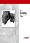
Figure 1.1 Logix Architecture Overview
31104
1
Publication 1757-SO001B-EN-P - June 2001
1-2
Rockwell Automation Logix System: DCS Process Capability, PLC Scalability and Flexibility
Rockwell’s Logix system is unique because the same chassis,
communication modules, and I/O modules used in ProcessLogix
(DCS) are also used by the non-DCS multi-functional ControlLogix. In
fact, the two systems, ProcessLogix and ControlLogix work
side-by-side, providing a degree of control and openness from a
single system never before achieved (See Figure 1.2).
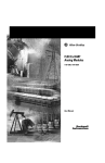
Figure 1.2 Sample Logix System Architecture
31180
ProcessLogix provides the tight integration of human-machine
interface (HMI) and control. It also integrates the server-based
common database that is typical of DCS systems and required for
many process operations.
At the same time, the ControlLogix system supplements this by
providing IEC 1131 loop control capability together with high speed
discrete and motion control for ancillary operations such as packaging
and material handling. And because both share the same I/O data,
both control systems will simultaneously reflect events on the plant
floor automatically.
Publication 1757-SO001B-EN-P - June 2001
Rockwell Automation Logix System: DCS Process Capability, PLC Scalability and Flexibility
Benefits of a Rockwell
Automation Logix System
1-3
Rockwell’s Logix Architecture provides the first hybrid system by
integrating the process control of Distributed Control Systems (DCS)
and the discrete/sequential control of Programmable Logic Controller
(PLC)-based systems.
For those highly integrated analog process applications, you can use
the ProcessLogix system out-of-the box to take advantage of
pre-engineered system parameters with no need for integration or
programming.
Or for the highly customized applications requiring: high speed,
regulatory functionality and a significant amount of discrete control,
you can use the ControlLogix controller.
In either case, you will benefit from the flexibility typically associated
with either controller as well as taking advantage of ControlNet
scheduled I/O messaging.
The key is that Logix provides network
communications, system development, and control
technology.
Unlike other control systems, the Logix system is based on a concept
of an open architecture. This automatically allows for:
• bridging of networks without the need for a controller
• placing any combination, arrangement, or quantity of
controllers, I/O modules, or communication modules in the
chassis
• removal and insertion under power (RIUP) of most modules
without disrupting the other modules in the system
Publication 1757-SO001B-EN-P - June 2001
1-4
Rockwell Automation Logix System: DCS Process Capability, PLC Scalability and Flexibility
For high-speed, motion and discrete control, you can integrate
ControlLogix into the ProcessLogix system without using gateways or
special interface cards.
Seamless
Fast
Enables easy integration between different/multiple Logix controllers
and with existing PLC-based systems. Users on existing networks can
send or receive messages to/from program controllers on other
networks transparently.
The Logix architecture provides high-speed data-transfers across the
backplane and between the controllers for a high-speed control
platform.
Scalable
Provides a modular approach to control. Add controllers and
communication modules as your system grows. You can have multiple
controllers in the same chassis. Select the controller type to meet your
application needs.
Industrial
Offers a hardware platform designed to withstand the vibrations,
thermal extremes, and electrical noise associated with harsh industrial
settings.
Integrated
Establishes a platform that integrates multiple technologies, including
sequential, motion, drive, and process applications.
Compact
Flash Upgradeable
Meets the needs of many applications where control is highly
distributed and panel space is limited.
I/O modules and other device revisions are flash upgradeable using
NTools, which flags firmware that needs to be upgradded.
ProcessLogix System for Cost Effective DCS
ProcessLogix utilizes current PC/computer technologies that include:
• cost effective PC’s using a powerful Microsoft Windows
NT-based system Server with dynamic data caching, alarming,
human/machine interface, history collection, and reporting
functions
• ControlNet, an open, state-of-the-art producer/consumer control
network
• Interfaces to legacy Allen-Bradley products as well as third-party
devices (SCADA)
Publication 1757-SO001B-EN-P - June 2001
Rockwell Automation Logix System: DCS Process Capability, PLC Scalability and Flexibility
1-5
• interfaces to a wide range of Allen-Bradley I/O devices, such as
FLEX I/O, FLEX Ex modules, PLC-5 processors, and
process-specific modules
• object-oriented tools to quickly and easily build reusable control
strategies
• development software, including:
– Control Builder with Continuous and Sequential Control
libraries
– Discrete logic tools and configuration utilities
– Integrated Operator Interface (OI) displays, custom graphics,
alarm diagnostics, history, and reports
With ProcessLogix, you configure the system instead of building it
from scratch. Most industrial process control applications call for a
number of common elements, such as communications protocols and
control algorithms. ProcessLogix has built-in elements within the
standard operating framework, allowing you to concentrate on the
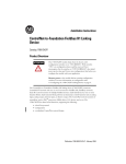
application, not the integration. See Figure 1.3 for a sample of a
standard ProcessLogix System configuration.
Figure 1.3 Sample ProcessLogix System Configuration
Historian
ProcessLogix Server
Client PC/Operator Station
RSBatch
Quick Builder
for SCADA
To 3rd Party Devices/Remote
Control Builder
RSLinx
ControlNet
1757-PLX52
1757-PLX52
42766
1756-CNB as
Remote I/O
controlled by
1757-PLX52
The ProcessLogix system lets you start working as soon as I/O and
hardware configuration is complete, with a minimum of system
Publication 1757-SO001B-EN-P - June 2001
1-6
Rockwell Automation Logix System: DCS Process Capability, PLC Scalability and Flexibility
building required. With ProcessLogix, the system is up and running in
minimum time.
The ProcessLogix System is built with Rockwell Automation’s
world-class Allen-Bradley control components. The system features:
• 1757, 1756, 1794, and 1797 series I/O, the most robust in the
industry
• widely-used control communication protocols, including:
– DeviceNet
– ControlNet
– Ethernet/IP
– Data Highway+ (DH+)
– FOUNDATION Fieldbus
• Optimized controllers for process and discrete control:
Although the ProcessLogix controller has regulatory discrete control
capability, often this type of configuration is not enough to solve
tough high speed custom control applications, such as packaging.
Network Communication Technology
Common to all of the Logix platforms is a new approach to
communication that enables you to control, configure and collect
information from all devices on the plant floor. The NetLinx
architecture makes this possible in products that connect via
EtherNet/IP, ControlNet, DeviceNet and Foundation Fieldbus. The
variety of networks available from the NetLinx architecture enables
you to choose the type of network, media, devices and topology their
application requires, or to mix and match networks as appropriate
without adding complexity or sacrificing performance.
Publication 1757-SO001B-EN-P - June 2001
Rockwell Automation Logix System: DCS Process Capability, PLC Scalability and Flexibility
Allen-Bradley
Communication Networks
Overview
1-7
NetLinx Communication
Rockwell Automation offers you a choice of networks and a broad
scope of products to fit your unique application through its NetLinx
Open Architecture.The NetLinx Open Architecture is a combination of
network services with a common wire-independent protocol and
open software interfaces to help ensure the efficient flow of your
information and control data up and down your organization
seamlessly.The NetLinx Open Architecture is conceptual and is used
to describe these open networks:
• DeviceNet
• ControlNet
• EtherNet/IP
The NetLinx architecture, a combination of wire-independent
networks with open software interfaces, helps ensure the efficient
flow of your control data and information. The NetLinx architecture is
designed to include overlapping device, control, and information
networks and bring you a more efficient way to combine these
networks without sacrificing performance. Based on your application,
you can mix any of the three networks without extra programming or
routing tables.
Open indicates that the specifications and technology are not
managed or governed by Rockwell Automation.
Control and Information Protocol (CIP) is a major component within
the NetLinx open network architecture, and it provides you with four
common features:
• common control services - provide you with a standard set of
messaging services for all three networks within the NetLinx
architecture
• common communication services - let you connect to any
network and configure and collect data from any network
• common routing capabilities - save time and effort during
system configuration because no routing tables or added logic
are necessary to move data between networks
• common base knowledge - reduces the amount of training
needed when moving to different networks within the NetLinx
architecture by providing similar configuration tools and features
Publication 1757-SO001B-EN-P - June 2001
1-8
Rockwell Automation Logix System: DCS Process Capability, PLC Scalability and Flexibility
With the NetLinx open network architecture you can:
Control Provides real-time data exchange in a variety of methods: selectable
I/O refresh rates, single producer or multi-producer systems, shared
inputs, peer-to-peer messaging, and interlocking between controllers.
Configure Able to configure all network devices from any network location. You
can configure devices upon start-up, modify device parameters with a
click of a mouse or through controller logic without having any
impact on control performance. You no longer have to move from
network to network for configuration purposes. Now, you can set-up
your entire system from one location with one connection.
Collect Provides a perfect solution for HMI display, trending and analysis,
recipe management or for maintenance and troubleshooting. This can
be done at regular intervals or on-the-fly.
The NetLinx open network architecture is efficient because of its
producer/consumer networking services and standard hardware and
software interfaces. On producer/consumer networks, if a node needs
the packet, it will consume the packet. So the producer sends that
packet once, and all the nodes consume the same packet if they need
it. This breakthrough brings you:
• increased efficiency because data is produced once, regardless
of the number of consumers
• precise synchronization because data arrives at each node at the
same time
Publication 1757-SO001B-EN-P - June 2001
Rockwell Automation Logix System: DCS Process Capability, PLC Scalability and Flexibility
1-9
Open Communication Networks
The Allen-Bradley open communication architecture offers seamless
connectivity between plant-floor devices, peer control devices, and
business computing systems. Our architecture includes three levels of
networks:
• the control and information network, (EtherNet/IP) is an open
industrial networking standard that supports implicit messaging,
explicit messaging or both and uses commercial off-the-shelf
Ethernet communication chips and physical media.
• the control and automation network, (ControlNet) which allows
intelligent automation high-speed control devices to share the
information required for supervisory control, work-cell
coordination, operator interface, remote device configuration,
programming, and troubleshooting.
• the device network, (DeviceNet) which offers high-speed access
to plant-floor data from a broad range of plant-floor devices with
a significant reduction in wiring.
EtherNet/IP, ControlNet, and DeviceNet are open networks. With our
open architecture you’re not restricted to buying only A-B devices if
you implement an A-B network.
Rockwell Automation developed the ControlNet and DeviceNet
baseline specifications and made them available to independent
organizations who took ownership of the specifications. For example,
the Open DeviceNet Vendors Association (ODVA) was formed to take
ownership of the specification and support worldwide growth of
DeviceNet. To date, more than 400 companies are supporting
DeviceNet, ControlNet, and EtherNet/IP products. EtherNet/IP is
managed by ControlNet International and ODVA.
Our open communication architecture lets you bring plant-floor data
from low-level devices to personal computers and mainframes that
run on multiple operating systems.
Publication 1757-SO001B-EN-P - June 2001
1-10
Rockwell Automation Logix System: DCS Process Capability, PLC Scalability and Flexibility
This table helps you determine which Allen-Bradley networks provide
the best solution for your application needs.
Table 1.A Allen-Bradley Solutions for Your Needs
DeviceNet
Network
ControlNet
Network
EtherNet/IP
Network
Universal
Remote I/O
Link
DH-485
Network
DH+ Network
Function
Connects
low-level
devices directly
to plant-floor
controllers
without
interfacing them
through I/O
modules
Supports
transmission of
time-critical data
between PLC
processors and
I/O devices
Plant management
system tie-in (material
handling);
configuration, data
collection, and control
on a single high-speed
network; time-critical
applications with no
established schedule
Provides
connection
between PLC
processors and
I/O adapters
Provides
connection
between SLC
processors,
MMI, and
programming
devices
Permits
plant-wide and
cell-level data
sharing with
program
maintenance
Typical
Devices
Networked
Sensors, motor
starters, drives,
PCs, push
buttons, low-end
MMIs, bar code
readers, PLC
processors, valve
manifolds
PLC processors,
I/O chassis,
MMIs, PCs,
drives, robots
Mainframe
computers, PLC
processors, robots,
HMI, I/O and I/O
adapters
PLC processors,
I/O chassis,
drives,
PanelView
operator
terminals,
RediPANEL
operator
modules
SLC
processors,
PCs, low-end
MMIs
PLC processors,
PCs, high-end
MMIs
Data
Repetition
Small packets;
data sent as
needed
Medium-size
packets; data
transmissions are
deterministic and
repeatable
Large packets, data
sent regularly
Medium-size or
small packets;
data sent
regularly
Small
packets: data
sent
periodically
or as needed
Medium-size
packets; data
sent regularly
Number of
Nodes (max)
64 logical
99
No limit
1 scanner and 32 32
adapters
64 per link
(network can
have 99 links)
Data Transfer
Rate
500, 250, or 125k 5M bit/s
bit/s
10M bit/s
100M bit/s
230.4, 115.2, or
57.6k bit/s
57.6k bit/s
Device
Suppliers
Open
Open
Open
Rockwell Automation and its partners
Example
Functions
Control,
configure and
collect data.
Networking
sensors and
actuators to a
PLC processor or
a PC to reduce
field wiring and
increase
diagnostics
Control, configure
and collect data.
PLC processor
controlling remote
I/O chassis,
peer-to-peer
messaging with
other controllers
using redundant
media
connections for
time-critical
applications
Control, configure and
collect data. Using a
single PC for data
acquisition form many
PLC processors, or
using a single PC to
program up/download
multiple PLC
processors for
non-time-critical
messaging between
controllers
PLC-5 processor
controlling I/O
chassis,
PanelView
operator
terminals, 1336
drives, and
third-party
welders and
valves
Publication 1757-SO001B-EN-P - June 2001
19.2 bit/s
Programming
connection
between a PC
and one or
more SLC 500
processors in
a small plant
Using a single
PC on one link to
program
multiple PLC
processors on
multiple links
within a network
throughout a
plant
Rockwell Automation Logix System: DCS Process Capability, PLC Scalability and Flexibility
The ProcessLogix System
1-11
The ProcessLogix system is a modular, supervisory control and
networking system designed around the Rockwell Automation
architecture and a high-performance, Microsoft Windows NT-based
Server. All components of this system are fully integrated. For
example, when a user-built Control Module is created and loaded to
the controller, required process data parameters automatically loads to
both the 1757-PLX52 Control Processor and the Server database. This
data processing eliminates the effort normally associated with a
component based system, which requires the definition of multiple
databases. A Server database point is built for each named block,
function, and parameter that you define in Control Builder.
Features like navigation tools and integrated alarming give your
system a consistent look and feel from the operator station to the
controller. Consistent tag names are used throughout the system
which helps to maintain the large amounts of data.
Figure 1.4 The ProcessLogix System
42756
Publication 1757-SO001B-EN-P - June 2001
1-12
Rockwell Automation Logix System: DCS Process Capability, PLC Scalability and Flexibility
Table 1.B Components of the ProcessLogix R320.0 System
Component:
See Page:
The ProcessLogix Server
1-13
SCADA Interface/Database
1-15
On-line Remote Data Management
1-17
Controller Interfaces and Connection Types
1-18
Human Machine Interface (HMI)
1-19
ProcessLogix System Status Functions
1-21
Security
1-26
Application Enablers
1-27
Application Toolkit
1-30
System Development Tools
1-31
Figure 1.5 Controller points are accessible to the operator via standard displays
and to MIS via OBDC/OPC.
Publication 1757-SO001B-EN-P - June 2001
Rockwell Automation Logix System: DCS Process Capability, PLC Scalability and Flexibility
The ProcessLogix Server
1-13
ProcessLogix architecture, the combination of server/ControlNet/
EtherNet/IP ensures that you have complete and transparent access to
the Controller database. ProcessLogix also integrates with a wide
range of other Rockwell Automation and third-party devices,
leveraging existing control investments and enabling complete
integration of process information. Process information is accessible
by operators, process engineers and MIS level computers, allowing
control and monitoring for higher productivity, reductions in costs,
higher product consistency, and less waste.
Data Repository The Server is the system data repository. The common database
structure provides an efficient, single source access point for system
information. To maintain system performance, a dynamically
scheduled cache in the Server gathers all data requests, providing
optimal data access performance and memory utilization while
minimizing the data access load on the Control Processor.
Controller and Server Configuration Control Builder configuration includes information for both the
Controller and ProcessLogix Server. With an integrated database,
information is entered once, not repeated in several databases. The
Server features a true Client/Server architecture where a real-time
database on the Server provides data to a number of client
applications including:
• operator stations
• third-party applications (such as Microsoft Excel, Microsoft
Access, LIC Energy)
• web pages
Publication 1757-SO001B-EN-P - June 2001
1-14
Rockwell Automation Logix System: DCS Process Capability, PLC Scalability and Flexibility
ProcessLogix R320.0 Server Benefits and Features
Through your purchase of the ProcessLogix server, configured by
expert technicians at Rockwell Automation, you also recieve the
following:
•
•
•
•
Rockwell Automation support
performance consistency
robust functionality
reliability
The ProcessLogix R320.0 Server includes the following features:
Windows NT
• Windows NT-based Server and Windows NT or Windows 95/98
based client HMI
Redundancy
• Complete server redundancy
• support for redundant controller/RTU communications
Real Time Access
SCADA Support
• real-time data access for a wide variety of process connected
devices
• direct support of SCADA (supervisory control data acquisition)
for controllers and remote terminal units
Industry Standards
• industry standard local and wide area network integration
Foundation Fieldbus
• FOUNDATION Fieldbus interface - high level interface to the
emerging field industry bus network
Operator Stations
Sophisticated Built-in Status Functions
• multiple local and remote operator stations operating as clients
from the command database
• alarm functionality to assist in the management of process
systems
• extensive server based historization and trending capability with
extensions to 3rd party packages
• flexible standard or customized data reporting
• ActiveX document and scripting support
• secure HTML access within Station window via SafeBrowse
• secure data integration with third party applications
Applied Media
• live video integration
For Server sizing and other specifications, see Chapter 2.
Publication 1757-SO001B-EN-P - June 2001
Rockwell Automation Logix System: DCS Process Capability, PLC Scalability and Flexibility
1-15
Server Redundancy
As an option, the ProcessLogix Server can be easily made redundant.
The ProcessLogix Redundancy subsystem software enables a pair of
similarly configured ProcessLogix Servers to support each other in a
primary/backup fashion. Primary refers to the specific ProcessLogix
Server which is actively acquiring data from the controllers/RTUs and
serving data to the clients. Should the Primary fail, a fully functioning
Backup assumes the Primary role. The Primary propagates all
database transactions to the Backup over a redundant network, so that
both databases remain completely synchronized.
SCADA Interface/Database
The ProcessLogix system provides Supervisory Control and Data
Acquisition (SCADA) facilities to communicate with a wide range of
SCADA controllers and RTUs. See Table 1.C on page 1-18 for a list of
controllers/RTU interfaces.
While this capability remains independant from the PLX/CLX system,
it extends the functionality of the system by maintaining both the
SCADA and the PLX/CLX process data in the same global database
This capability also gives the operator access to both the SCADA and
the process data.
SCADA Data Acquisition
The process of SCADA data acquisition by the ProcessLogix server has
been optimized by using either:
• Periodic Scanning ProcessLogix optimizes communication
traffic by calculating the minimum number of scan packets
required to collect data.
• Report by Exception (RBE) This technique is used to reduce
the scanning load of the system while improving system
response.
If necessary, periodic scanning may be used in conjunction with RBE
to ensure data integrity, and optimized data acquisition.
Publication 1757-SO001B-EN-P - June 2001
1-16
Rockwell Automation Logix System: DCS Process Capability, PLC Scalability and Flexibility
The ProcessLogix SCADA driver provides an interface to third-party
devices. The drivers connect the devices to the global database. This
connection provides the following standard system structures:
•
•
•
•
Analog Point Structure
Status Point Structure
Accumulator Point Structure
User Defined Structure
Using these drivers, each point in the database has a number of
associated parameters, all of which can be referenced relative to a
single tag name or composite point.
The ProcessLogix server manages SCADA device data in real time
database which maintains frequent high-speed access as
memory-resident information and other less frequently accessed data
as disk-resident data, optimizing the system. Memory resident data is
also checkpointed to disk every minute to minimize loss of data in the
event of power loss.
SCADA Control Algorithms
In addition to standard point (data) processing functions, the Server
provides additional control processing through the use of configurable
algorithms that may be attached to an analog, status or accumulator
point to allow manipulation of the SCADA information. Functions
provided by these algorithms include:
•
•
•
•
•
•
•
•
Publication 1757-SO001B-EN-P - June 2001
arithmetic calculations
boolean calculation
maximum/minimum value
integration
run hours totalization
group alarm inhibit
report request
application program request
Rockwell Automation Logix System: DCS Process Capability, PLC Scalability and Flexibility
On-line Remote Data
Management
1-17
With administrative privileges, you can view, manipulate and analyze
all data in the system from any client/operator station in the system,
including those operating remotely via dial-up modem links.
Diagnostics
Once a SCADA controller or RTU is configured and placed in service,
diagnostics begin. The Server automatically:
• performs diagnostic scanning of the device
• performs checks on data integrity of all data acquired from the
controller
• records errors
Should an invalid or timed-out response be received, the data is
ignored and the transaction is recorded as an error.
• records statistics
Statistics are kept and displayed by a communications
barometer. The barometer increments for every failed call and
decrements for each successful call. If a controller fails, all point
parameter values that are sourced from it are indicated as bad to
the operator.
• activates alarm parameters
The system alarms separate marginal and failure conditions
based on user defined limits to advise the operator of a
controller that is in error.
Publication 1757-SO001B-EN-P - June 2001
1-18
Rockwell Automation Logix System: DCS Process Capability, PLC Scalability and Flexibility
Controller Interfaces and
Connection Types
The table below lists the controller and connection types. Refer to the
ProcessLogix on-line documentation, Knowledge Builder for extensive
information about controller connectivity.
Example Controller: An Allen-Bradley Interface
The ProcessLogix system is tightly integrated with the PLC-5/SLC
range of controllers. For example, the system provides standard,
automatically generated diagnostic displays. In addition any alarms,
such as rack faults, major or minor faults, are automatically alarmed in
the standard alarm summary display. No configuration is required.
The ProcessLogix system also provides complete access to the A-B PD
(PID Configuration) or Rockwell Automation Smart Transmitter files
when you build a single point.
Table 1.C Interfaces with connection details
Publication 1757-SO001B-EN-P - June 2001
Controller/RTU
Connection type
Allen-Bradley SLC5/xx
Allen -Bradley PLC-5
Allen-Bradley ControlLogix
Honeywell S9000
Honeywell LCS620
Honeywell Data Hiway
Honeywell UDC
Honeywell Micromax
Honeywell Flame Safeguard
Honeywell DPR
Honeywell XLNET
Honeywell FSC
Honeywell FS90
Honeywell UMC
Modicon
AdvanceDDE
OPC Client
Bristol Babcock DPC
SquareD
Siemens S5/S7
Yamatake Honeywell MA500
Moore Mycro
Moore APACS
Fieldbus
GE Fanuc Series 90
ASEA
Universal Modbus
Applicom
Bailey
Hitachi
Serial/Ethernet/DH+
Serial/Ethernet/DH+/ControlNet
Serial/Ethernet/DH+/ControlNet
Ethernet
Serial/Ethernet
Proprietary
Serial
Serial
Serial
Serial
CBus
Serial and Ethernet
Serial
Serial
Serial/Modbus+
Open Standard
Open Standard
Serial
Ethernet and Synet
H1/Industrial Ethernet
Serial
Serial
Ethernet & Modulbus
Open Standard
Ethernet
Serial
Serial/Modbus+
Proprietary
Ethernet, SCSI & Serial
Serial
Rockwell Automation Logix System: DCS Process Capability, PLC Scalability and Flexibility
Human Machine Interface
(HMI)
1-19
State-of-the-art, object-based graphics provide a powerful interface.
The use of industry standards, such as Microsoft Windows NT,
Windows 95/98, and the Internet, minimizes operator training by
providing a familiar operating environment.
User configurable pull-down menus and toolbars allow easy, intuitive
navigation and fast access to key process data. The usability of the
operator interface is further enhanced with features such as last
command recall, copy and paste, live video integration, ActiveX
documents, scripting, launching applications and support for standard
peripherals such as:
•
•
•
•
•
Station operator interface software
sound cards
touch screens
dual screens video cards
pointing devices
Critical information is conveyed using dedicated annunciators for
alarms, controller communication failures, operator/controller
messages and equipment downtime conditions. An alarm line at the
bottom of each graphic shows the most recent (or oldest), highest
priority, unacknowledged alarm at all times. Standard system displays
make it easy for operators to learn and use the system. See Figure 1.6
for a sample display.
Figure 1.6 ProcessLogix Operator Interface
Publication 1757-SO001B-EN-P - June 2001
1-20
Rockwell Automation Logix System: DCS Process Capability, PLC Scalability and Flexibility
An extensive range of standard displays available include:
•
•
•
•
•
•
•
•
•
•
•
Menu/navigation displays
Alarm summary
Event summary
Trends
Operating groups
Point details
System status displays
Configuration displays
Loop Tuning displays
Diagnostic and maintenance displays
Summary displays
ProcessLogix Operator Interface Features
Standard Detail Standard Detail displays for I/O are an example of the 300 standard
displays that are included with the system. You can operate from
these displays or, if you choose, create custom displays.
Video Integration Live video integration is an important feature where remote sites may
be unmanned. ProcessLogix not only allows the operator to view live
video from remote locations but also provides the ability to switch
cameras, and pan, tilt or zoom the camera to focus in on a particular
area. An alternative to live video is WebCam. WebCam allows a CCTV
camera to be connected to Ethernet/IP, and is therefore available to all
operator stations via SafeBrowse.
SafeBrowse SafeBrowse allows the user to securely browse either the Internet or
an Intranet. This allows the system to view corporate documents, such
as Standard Operating Procedures, from across the world, or to keep
operators informed of relevant product information. SafeBrowse has
three levels of security:
• Unrestricted
• Restricted (limited to certain URLs)
• No Access
Rotary Connected Stations Rotary Connected Stations permit any number of operator stations on
a network to share a preconfigured number of connections to a
ProcessLogix system. This allows a large number of users on a
network to access production data on a part-time basis.
Publication 1757-SO001B-EN-P - June 2001
Rockwell Automation Logix System: DCS Process Capability, PLC Scalability and Flexibility
ProcessLogix System
Status Functions
1-21
The ProcessLogix System provides comprehensive alarm and event
detection, management, and reporting facilities. Depending on the
level of your security authorization (based on logon IDs), you can
view, acknowledge and addess alarms from any station. The level of
reaction/edits to alarms can also be controlled by security
authorizations. One of the keys to operator effectiveness is
presentation of alarm information. Many tools are provided to quickly
target the process problems, including:
•
•
•
•
•
•
•
•
•
•
•
multiple alarm priorities
dedicated alarm zone
associated display
audible alarms
alarm cutout
area assignment
operator log
hierarchical alarming
alarm/event reporting
alarm/communication/message/downtime annunciator
alarm priority escalation
Alarm Levels
The ProcessLogix System provides two alarm levels:
• System Level Alarms
– internal to ProcessLogix based on your system configuration
– automatically generated on, for example, health of I/O
modules, and communication between server and racks
• Process Level Alarms
– configured and programmed at the Function Block level
– configured to report on, for example, temperature, flow rates,
and sensor functions
Publication 1757-SO001B-EN-P - June 2001
1-22
Rockwell Automation Logix System: DCS Process Capability, PLC Scalability and Flexibility
Alarm Summary
The standard Alarm Summary display allows operators to focus in on
the problem at hand by supporting filters. Alarms may be filtered by:
• area
• acknowledge status
• priority
Alarms on the Alarm Summary display can be acknowledged either
individually or per page. On custom graphics, alarms can similarly be
acknowledged on an individual or per page basis. The standard point
alarm behavior is the alarm will flash red if unacknowledged and in
alarm and be steady red if acknowledged, yet still in the alarm
condition. Up to 4 alarms can be configured for a point. Supported
alarms include:
•
•
•
•
•
•
•
PV Hi
PV Lo
PV HiHi
PVLoLo
Deviation Hi
Deviation Lo
Rate of Change
Each of the configured alarms can be assigned a priority ranging from
Journal, Low, High to Urgent. In addition to the configurable alarms
ProcessLogix supports, a range of other point alarms including Control
Fail and Control Timeout.
Publication 1757-SO001B-EN-P - June 2001
Rockwell Automation Logix System: DCS Process Capability, PLC Scalability and Flexibility
1-23
Event Summary
The Event Summary lists all events that occur in the system, including:
•
•
•
•
•
•
•
•
Alarms
Alarm Acknowledgments
Return to Normal
Operator Control Actions
Operator Login & Security Level Changes
On-line Database Modifications
Communications Alarms
System Restart Messages
Up to 30,000 events may be stored in the Event Summary. The
extended Event archiving option enables up to one million events to
be stored online, in addition the events can be archived to removable
media for access at a later date.
Historization
History collection is available over a wide range of frequencies in
both average and snapshot/production formats. A large amount of
history can be retained on line, with automatic archiving allowing
retention of and access to unlimited quantities of historical data.
The default history collection intervals are:
•
•
•
•
•
•
•
•
•
5-second snapshot
1-minute snapshot
1-hour snapshot
8-hour snapshot
24-hour snapshot
6-minute average
1-hour average
8-hour average
24-hour average
Once collected historical data is available for use by trend facilities,
custom displays, reports, application programs, spreadsheets and
ODBC compliant databases. Archives can be stored on the local hard
drive, optical media, tapes, etc.
Publication 1757-SO001B-EN-P - June 2001
1-24
Rockwell Automation Logix System: DCS Process Capability, PLC Scalability and Flexibility
Trending
Flexible Trend Configuration allows trends to be configured online as
necessary by simply entering the point and selecting the parameter
from the database. Any of the history collection intervals may be used
as the basis. Standard trend types include:
•
•
•
•
•
•
•
•
•
Single bar graphs
Dual bar graphs
Triple bar graphs
Multi-plot trends
Multi-range trends
X-Y scatter plots,
Numeric tables
S9000 and Micromax Set Point Program plots
Group trends
Functions provided for analyzing and manipulating data include:
•
•
•
•
•
•
•
•
Combination real-time/historical trending
Trend zooming, panning, and scrolling
Hairline readout
Declutter
Configurable trend density
Simple recall of archived history
Trend protection
Smart clipboard support for copy/paste of data
The declutter feature, for example, enables individual traces on
multi-type trends to be temporarily disabled for clearer viewing
without requiring reconfiguration of the trace. Trends may be easily
configured on line through standard trend displays, without the need
to build displays. Real-time and historical data are presented together
on the same trend. Archived history may be accessed automatically by
simply scrolling to, or directly entering, the appropriate time and date.
Publication 1757-SO001B-EN-P - June 2001
Rockwell Automation Logix System: DCS Process Capability, PLC Scalability and Flexibility
1-25
Reporting
The supervisory system provides many built-in reporting functions.
Standard report descriptions include:
Table 1.D Reporting Functions
Built-in Reporting Functions
Description
Alarm/Event Log
Reports all alarms and events in a specified time
period. By using filters, this report provides an operator
and/or point trace facility.
Alarm Duration Log
Reports the time of occurrence and elapsed time
before return-to-normal for specific alarms in a
specified time period.
Integrated Excel Report
Provides the ability to launch a report built using
Microsoft Excel in a similar way to all other standard
reports. Microsoft Excel can access the ProcessLogix
database using the Open Data Access option.
Optional Downtime Analysis
Provides reports of downtime events sorted by
category and/or reason codes.
Free Format Report Writer
Generates reports in flexible formats, which may
include math and statistical functions such as
Max/Min and standard deviation.
Point Attribute Log
Reports on points displaying specific attributes, such
as off-scan, bad data, and alarm inhibit.
Point Cross-Reference
Determines database references for specified points to
enable easier system maintenance when points are
decommissioned or renamed.
ODBC Data Exchange Reports
Reports may be generated periodically, or on an
event-driven or demand basis and may be configured
on line. Report output may be directed to screen,
printer, file, or directly to another computer for analysis
or viewing electronically.
Refer to Application Enablers on page 1-27.
Publication 1757-SO001B-EN-P - June 2001
1-26
Rockwell Automation Logix System: DCS Process Capability, PLC Scalability and Flexibility
Security
To maintain system security, ProcessLogix provides configurable
security levels, control levels and area assignments. These may be
configured for each individual operator or alternatively for each
operator station. Up to six security levels limit operator access to
ProcessLogix functions, see Table 1.E.
Table 1.E Security Modes
Security
Level
Operator Mode
1
Signed-off mode
2
View only mode with alarm acknowledge
3
Level 2 plus control of field parameters
4
Level 3 plus field parameters of Level 4, configure standard
system infrastructure such as reports
5
Level 4 plus user configured field parameters
6
Unlimited access
Operator sign-on/sign-off security provides up to 255 control levels to
limit operator control of individual items of plant and equipment. Any
actions initiated by an operator are logged in the Event database by an
operator identifier. In addition any control actions to a given point is
only allowed if the control level configured in the operator profile
exceeds the level assigned to the point.
An operator password consists of 5-6 alphanumeric characters and is
encrypted. Operators may change their own passwords, however a
new password can’t be the same as the last 10 passwords used in the
previous 3 months. When signing on, three unsuccessful attempts will
lock the operator out for a lock-out period. Once signed on (logged
on), an operator can sign off (log off) at any time or will be
automatically signed off after a defined period of inactivity.
Area assignments limit operator access to graphics, alarms and point
data to assigned areas, providing effective plant partitioning.
Individual operator profiles, including security levels, control levels
and area assignments, are activated when operators sign on to the
system.
Publication 1757-SO001B-EN-P - June 2001
Rockwell Automation Logix System: DCS Process Capability, PLC Scalability and Flexibility
Application Enablers
1-27
The ProcessLogix System provides powerful application enablers with
configurable (rather than programmatic) facilities to support individual
application requirements. Application implementation time is greatly
reduced, providing extremely cost effective automation.
Recipe Management Recipe Management lets you create recipes and download them to
nominated process units. Each recipe may have up to thirty items,
with recipes chained together to form larger recipes if required.
Recipe items may be used to set ingredient targets, set alarm limits, set
timers and place equipment into correct operating state. Items may be
individually enabled for scaling.
Downtime Analysis Downtime Analysis may be used to detect, record and code any
equipment breakdowns or process delays to provide plant downtime
analysis. A list of all current downtime events is maintained as well as
the history of previous downtime events, with each assigned a
category and a reason code. Downtime reports may be printed
periodically or on-demand, showing downtime duration sorted by
categories and reasons.
Point Control Scheduler The Scheduler option allows point supervisory control to be
automatically scheduled to occur at a specified time. This may occur
once, at a pre-determined interval, or on specific days.
SPQC The SPQC (Statistical Process & Quality Control) option provides
powerful statistical processing capabilities for real-time data collected
by the system. Facilities include on-line generation of control charts
for X-Bar and R-Bar, histograms and Sigma trends, Shewart’s
calculations for UCL (Upper Control Limit) and LCL (Lower Control
Limit), and on-line statistical alarming.
Extended Event Archiving Extended Event Archiving may be used when the events logged by
the system are required to be archived for later review. Storage
capacity is dependent upon media capacity, but storage of over 1
million events is easily achievable. Approximately 60 Mb of hard disk
space is required for every 100,000 events archived.
Alarms and Events Alarms are configured by Control Builder, generated by the Controller,
recorded into the event system, and acknowledged by operators on
the ProcessLogix Operator Station alarm summary display. Users do
not have to separately configure process alarms in both the controller
and the supervisory system.
Publication 1757-SO001B-EN-P - June 2001
1-28
Rockwell Automation Logix System: DCS Process Capability, PLC Scalability and Flexibility
Alarm Pager Point alarms may optionally be sent to an alarm paging or messaging
system. Up to 100 pagers can be configured, and each pager has a
schedule of operation so that users are only paged when they are on
call. The information they receive is what normally appears on the
alarm summary. For each phone number configured, the user may
specify the days of the week and times of the day that the pager is in
use. Points can be scheduled to ring one or more of the configured
pagers.
ODBC Data Exchange This option enables two-way exchange of data between the
ProcessLogix Server database and an ODBC-compliant local or
network third-party database. It uses standard Structured Query
Language (SQL) commands. The ProcessLogix Server acts as a client
application in this configuration. Information exchanged includes
point values, point history, and user file data. Databases that include
ODBC drivers include Microsoft SQL Server, Oracle 7, Microsoft
Access, and Sybase 10.
Open Data Access Whenever another application requires data from the ProcessLogix
database, Open Data Access is required. Some examples of when
Open Data Access is required are:
•
•
•
•
•
reading data into a Microsoft Excel Spreadsheet
running a query on the database from Microsoft Access
another ProcessLogix system requiring point data
an OPC Client requires point data
a user written application is accessing the database
Each of the above instances are considered users of Open Data
Access.
The main components of Open Data Access are described below:
ODBC Driver The ODBC Driver allows the Server database to be queried using SQL
commands from ODBC client applications, such as Microsoft Access.
The Server database is exposed as a number of read-only ODBC
tables including Points, Event History and Process History. Driver
features include:
•
•
•
•
•
Publication 1757-SO001B-EN-P - June 2001
Open read-only access to plant real-time and historical data
Throttling to prevent performance impact
Redundancy of data storage
Fully functional examples for productivity improvements
Optimized for Microsoft Access and hence other ODBC ad hoc
query/report applications.
Rockwell Automation Logix System: DCS Process Capability, PLC Scalability and Flexibility
1-29
OPC Server The ProcessLogix OPC Server capability allows a third-party OPC
client application to read/write ProcessLogix point parameters. The
OPC Server is based on Rockwell Automation’s HCI Server toolkit,
which in turn is based on OPC specification V1.0a. It supports all
mandatory OPC interfaces.
Network Server The Network Server provides extremely efficient, access to the
ProcessLogix database for network based applications such as
Microsoft Excel Data Exchange, Network Node Interface and Network
API options.
Data Exchange Microsoft Excel Data Exchange allows Microsoft Excel to obtain
real-time and historical data from the ProcessLogix system. This option
provides read and write access to data in one or more ProcessLogix
Databases, providing a powerful data consolidation and reporting
tool. Wizards for Microsoft Excel are included to help set up the data
to be collected.
Network Node Interface When Network Node Interface is licensed on a ProcessLogix Server it
can read/write point data to another ProcessLogix Server.
Network API Applications executing on other network connected platforms may
easily access ProcessLogix real-time data over the network using the
Network API. The API provides high level subroutine calls in Visual
C/C++ or Visual Basic to allow read/write access to ProcessLogix data
in a networked environment.
FOUNDATION Fieldbus FOUNDATION Fieldbus measurement and actuation devices can be
integrated into ProcessLogix regulatory, sequential and logic control
operation. A ControlNet to FOUNDATION Fieldbus Linking Device
allows the powerful ProcessLogix Controller to interface with Fieldbus
devices, such as valves, transmitters and sensors. Recent Rockwell
testing found that the controller can communicate to eight pressure
transmitters via FOUNDATION Fieldbus.
Publication 1757-SO001B-EN-P - June 2001
1-30
Rockwell Automation Logix System: DCS Process Capability, PLC Scalability and Flexibility
Application Toolkit
Two types of application programming interfaces (API) are available.
The first is for applications written on the ProcessLogix Server and the
second is for applications that are required to run on network based
clients (not necessarily operator stations).
C/C++ The API (programmed in C/C++) on the Server includes the following
functions:
•
•
•
•
•
•
read and write to point parameters in the database
access to historical data
initiate supervisory control actions
access to the alarm/event subsystem
access to user-defined database
provide a prompt for operator input
Visual Basic or Visual C/C++ The API (programmed in VB (Visual Basic) or Visual C/C++) on the
network-based clients includes the following functions:
•
•
•
•
•
•
Publication 1757-SO001B-EN-P - June 2001
read and write to control module parameters in the database
access to historical data
initiate supervisory control actions
access to user-defined database
create alarms/events
Engineering Tools
Rockwell Automation Logix System: DCS Process Capability, PLC Scalability and Flexibility
System Development Tools
1-31
ProcessLogix development software includes the following:
• Control Builder with Comprehensive Control Libraries for
process point building and Multiple Workstation use
• Display Builder for powerful operator graphic creation
• RSBatch for powerful batch solutions
• Quick Builder for quick configuration
• Knowledge Builder On-Line HTML-Based Documentation
• Fieldbus Configuration Utilities
Control Builder
Control Builder (See Figure 1.7) is a multi-window GUI
object-oriented developmental software, supporting the ProcessLogix
1757-PLX52 Controller system design, documentation, and monitoring.
It provides a comprehensive set of tools for handling I/O, continuous,
logic, motor, sequential, batch and advanced control functions
through a library of Function Blocks (FBs).
Figure 1.7 Control Builder
Publication 1757-SO001B-EN-P - June 2001
1-32
Rockwell Automation Logix System: DCS Process Capability, PLC Scalability and Flexibility
Function Blocks
Function Blocks (FBs) are basic objects provided by Rockwell
Automation to execute different control functions. Each block
supports parameters that provide an external view of what the block
is doing. FBs easily interconnect via “soft wires” to construct control
applications or strategies.
Function Blocks are grouped together and contained in Control
Modules (CMs) and, in the case of sequential FBs, Sequential Control
Modules (SCMs). SCMs greatly simplify batch logic implementation by
sequencing a group of process equipment through a series of distinct
steps to accomplish one or more process tasks. CMs and SCMs act as
“containers” for Function Blocks. This is a very powerful tool for
creating, organizing, and checking out control strategies.
See Figure 1.8 for an illustration of a simple Control Module -- in this
case a PID loop -- made up of basic FBs. In this example four FBs are
contained within the CM named FIC105. You can schedule each
Control Module at its own execution rate from 5 msec to 2 sec, and
then you can schedule Function Blocks and Control Modules to
execute in any desired order.
Figure 1.8 M (PID loop shown) using basic Function Blocks
Publication 1757-SO001B-EN-P - June 2001
Rockwell Automation Logix System: DCS Process Capability, PLC Scalability and Flexibility
1-33
Control functions currently supported in the ProcessLogix Control
Builder Libraries are listed in Knowledge Builder. Types of functions
blocks include the following:
Table 1.F Function Block Types and Examples
Function Block Types
Examples
• General Purpose Array (Numeric Flag Text)
• Message block supports for Operator
messages
Genernal Purpose
•
•
•
•
PV Algorithms
• Data Acquisition
• Totalizer
• General Linerarations
• PV Calculator
• Dead Time
• Lead/Lag
Regulatory Control Algorithms
•
•
•
•
•
•
•
Proporational, Intgral, Derivative (PID)
PID with Feedforward
Override Selector
Remote Cascade
Auto Manual
Switch
Fanout Block
•
•
•
•
•
•
Regulatory Calculator
Ratio Bias
Ramp/Soak
Positional Proportional
Pulse Length
Pulse Count
Discrete Logic
(per IEC 1131 standard)
•
•
•
•
•
•
•
•
•
•
•
•
•
•
•
•
•
•
•
•
2oo3 (2-out-of-3 voting)
AND
CHECKBAD
DELAY
EQ (Compare Equal)
FTRIG (Falling-Edged Trigger)
GE (Compare Greater Than or Equal)
GT (Compare Greater Than)
LE (Less Than or Equal)
LIMIT
LT (Compare Less Than)
MAX (Maximum)
MAXPULSE (Maximum Time Limit Pulse)
MIN (Minimum)
MINPULSE (Minimum Time Limit Pulse)
MUX (Multiplexer)
MUXREAL (Multiplexer, Real Number)
MVOTE (Majority Vote)
NAND
NE (Compare Not Equal)
•
•
•
•
•
•
•
•
•
•
•
•
•
•
•
•
•
•
•
•
nOON (n-out-of-N Voting
NOR
NOT
OFFDELAY
ONDELAY
OR
PULSE (Fixed Pulse Output)
QOR (Qualified OR)
ROL (Rotate Left)
ROR (Rotate Right)
RS (Reset-Dominant Flip-Flop)
RTRIG (Rising-Edged Trigger)
SEL (Selector Function)
SELREAL (Selector Function, Real Number)
SHL (Shift Left)
SHR (Shift Right)
SR (Set-Dominant Flip-Flop)
TRIG (Change Detect Trigger)
WATCHDOG
XOR (Exclusive Or)
Sequential Control Functions
(follows S88.01)
• Step FB
• Transition FB
• Handlers: Main, Interrupt, Check, Restart,
Hold, Stop, Abort
Data Exchange
• Request (Numeric, Flag, Text)
• Response (Numeric, Flag, Text)
I/O Channel
•
•
•
•
•
•
•
•
Flag
Numeric
Timer
Type Convert Block
Device Control (Motor Control)
Analog Input (AI)
Analog Output (AO)
Pulse Width Moduleation (PWM)
Rail I/O Series A (Input & Output)
Digital Input (DI)
Digital Output (DO)
Serical Interface Array (Numeric, Flag, Text)
Fieldbus Analog & Digital (Input & Output)
Additional function libraries are available as well. The built-in
capabilities of the Control Execution Environment (CEE) enable users
to take advantage of these library options.
Publication 1757-SO001B-EN-P - June 2001
1-34
Rockwell Automation Logix System: DCS Process Capability, PLC Scalability and Flexibility
Through the use of Function Blocks, Control Builder:
• enhances engineering productivity by enabling “top-down”
implementation, enabling the creation of reusable control
strategies,
• uses icons to represent control blocks which can be “wired”
together using simple point and click techniques,
• monitors control execution on-line and makes changes to
control parameters, thereby significantly simplifying control
strategy checkout, and
• allows templates to be created, modified and reused so that
control strategies can be built and duplicated with a minimum of
effort.
Control Builder also supports a multi-user control strategy
development and debugging environment. The function provides the
following:
• remote access to engineering databases across any media
capable of TCP/IP and UDP/IP communication
• password protected accessibility for maximum security
• several users can create, configure and load control strategies at
the same time from different workstations
• multiple users can have the same chart open, with full write
access to the first user who opens a chart
• all users can change controller values, based on their security
level, when multiple users open a chart for monitoring
Publication 1757-SO001B-EN-P - June 2001
Rockwell Automation Logix System: DCS Process Capability, PLC Scalability and Flexibility
1-35
What is a ProcessLogix point?
In the ProcessLogix system, each control module is considered a
point. In Control Builder, control strategies are developed by placing
function blocks into a control module. These function blocks contain
data elements that are closely related to the tags in RSView. This
means that many RSView tags can be contained within one
ProcessLogix point.
The circled control module in Figure 1.9 is represented by the
function blocks on the right. Each function block in this control
module has a unique set of data elements similar to the tags in
RSView. This control module, with all of its function blocks, and all of
their data elements, is one ProcessLogix point.
Figure 1.9 A ProcessLogix Point
Control Module
Function Blocks
Publication 1757-SO001B-EN-P - June 2001
1-36
Rockwell Automation Logix System: DCS Process Capability, PLC Scalability and Flexibility
Display Builder
Display Builder is an object-based, fully integrated custom display
builder for development of application specific graphics. Animation of
displays is completed quickly and easily with simple point and click
type configuration. A library of commonly used plant equipment such
as vessels, piping, valves, tanks, motors, etc., is supplied with Display
Builder to further speed graphic development.
Figure 1.10 ProcessLogix R320.0 Display Builder Boiler Example
In addition, you can use Template Displays to reduce configuration
time where similar displays need to be repeated throughout the
system. Process objects and color palettes allow quick and easy
creation of custom objects with or without 3D effects.
Graphic displays can be enhanced by using Visual Basic Scripting and
ActiveX components. Effects such as high-speed animation, tool tips,
and control of a station from an application are possible with VB
Scripting. Additionally, a wide array of ActiveX component types, such
as playing sound and video can be invoked.
Publication 1757-SO001B-EN-P - June 2001
Rockwell Automation Logix System: DCS Process Capability, PLC Scalability and Flexibility
1-37
RSBatch
RSBatch for ProcessLogix is one of the most powerful solutions
available for batch automation. Developed around S88.01, the
Instrument Society of America’s (ISA) international standard for batch
control, RSBatch uses modular batch automation to make jobs easier
for all types of process professionals.
RSBatch allows you to configure physical (equipment) and procedural
(recipes) models to execute batches, and to integrate control actions
and produciton information with a diverse selection of
complementary software.
RSBatch communicates with ProcessLogix through a Sequential
Control Module (SCM). The data server, which is included with
RSBatch, links to the SCM, giving ProcessLogix a tightly coupled batch
system.
For detailed information on RSBatch, see pages 3-11 through 3-21.
Quick Builder
Quick Builder allows users to configure points, controllers/RTUs,
stations and printers. Quick Builder leverages a relational database
engine (Microsoft Jet Engine) to provide greater productivity through
capabilities such as filtering user views of the database, multipoint edit
facilities and the intuitive Windows style interface. Other features that
the relational database provide are the user-defined fields that can be
used for termination schedules, wire numbers, etc., and a standard set
of reports.
Additions and modifications to the ProcessLogix system database can
be made while the system is on-line.
Publication 1757-SO001B-EN-P - June 2001
1-38
Rockwell Automation Logix System: DCS Process Capability, PLC Scalability and Flexibility
Knowledge Builder
Knowledge Builder, an on-line resource for system documentation, is
supplied with the ProcessLogix system. See Table 1.H on page 1-48
for Knowledge Builder components.
Figure 1.11 ProcessLogix R320.0 Knowledge Builder Performance Tool Main Menu
Fieldbus Configuration Tools
The Fieldbus Configuration Tools integrate the Controller with
Fieldbus devices. Key features include:
• Communication through the ControlNet path from the
ProcessLogix Server
• Block and Device tag and address setting
• An easy-to-use graphical environment for creating linkages,
loops and a schedule based upon Fieldbus concepts
• Configuration of hardware information, ControlNet network
addressing, Linking Device paths, Device descriptions, and the
base directory to store Device Description information
Publication 1757-SO001B-EN-P - June 2001
Rockwell Automation Logix System: DCS Process Capability, PLC Scalability and Flexibility
Determining Your System
Configuration
1-39
Because the ProcessLogix System is based on Logix products, you
have flexibility in determining the type of configuration to use. Use
the out-of-the-box hierarchical system for a degree of integration
typically associated with DCS applications. Or you can use the system
in a flat configuration to emulate PLC-type control.
Integrated deterministic network
ControlNet, a real-time process control network, features deterministic
data delivery optimized for real-time process control via single or
redundant media.
Flat System Configuration
For smaller process applications, a standard ProcessLogix system can
be configured as a flat system architecture. A flat system enables you
to use ControlNet for both Supervisory and I/O configurations.
Figure 1.12 Flat Network System Architecture
ProcessLogix Client running Station software
Server
PanelView
RSBatch
ControlNet
PLC-5
Processor
Logix 5000 Chassis 1757-PLX52
and 1756-CNB installed, device
PLC-5
Processor
with
Remote I/O
31126-M
In this configuration, the ProcessLogix System lets you take advantage
of ControlNet technology and scheduled I/O messaging to implement
a flat architecture.When running several devices on one wire in a flat
system, you would use scheduled I/O messaging to optimize your
data throughput.
Publication 1757-SO001B-EN-P - June 2001
1-40
Rockwell Automation Logix System: DCS Process Capability, PLC Scalability and Flexibility
In a flat architecture, I/O data and other information can be
transmitted via the same network, resulting in a deterministic network
configuration. This configuration requires RSNetworx.
With this network architecture, you need to configure Control Builder
to allow I/O modules to be connected through the uplink 1756-CNB
in slot 0. With the 1756-CNB in slot 0, Remote I/O can be located in a
chassis on the same ControlNet link as the other devices in your
ProcessLogix system (e.g., the 1757-PLX52 Process Control Module,
the chassis, and the Server).
Figure 1.13 Scheduled I/O messaging on a “flat” system
ProcessLogix NT Server
ControlNet
1757-PLX52
1757-PLX52
1756-CNB as Remote I/O
controlled by 1757-PLX52
1757-PLX52 to ProcessLogix Server (unscheduled)
1757-PLX52 to I/O (scheduled)
1757-PLX52 to 1757-PLX52 (unscheduled) peer-to-peer
Publication 1757-SO001B-EN-P - June 2001
31145-M
Rockwell Automation Logix System: DCS Process Capability, PLC Scalability and Flexibility
1-41
Hierarchical System Configuration
A hierarchical system is one in which communication layers or levels
have been established and the communications defined. A typical
hierarchical system has three levels, each level has been defined for
specific data and:
• I/O (Remote I/O) Downlink used to transmit data from I/O
devices such as modules to the controller over ControlNet.
• Supervisory Level (uplink) designed for inter-controller (peer
to peer) and processor data transmission as well as
controller-to-server communication and Ethernet/IP. Transmits
data such as alarms, event status, etc.
• Plant/Operator Level communicates information (rather than
raw data) to a human-machine interface (Such as ProcessLogix
Station software) for interpretation by the operator.
Figure 1.14 Hierarchical Network System Architecture
ProcessLogix Client with Station
Ethernet/IP
ProcessLogix Server running ERDB
Supervisory Link
Data error messaging
Logic
ControlNet or Ethernet IP Supervisory network (uplink)
Can link up to 10 controllers
Downlink up to 64 I/O,
scheduling required
Remote I/O
Unscheduled
PLC-5 Processor
PLC-5 Processor
Downlink Remote I/O
42767
Benefits of a hierarchical system include:
• Pre-configuration system parameters
• Parameters defined, no need for additional engineering
• Because the pre-engineered system is sized and tested for the
worst “data storm” conditions, you get the I/O updates and data
throughput you expect within the specified time
Publication 1757-SO001B-EN-P - June 2001
1-42
Rockwell Automation Logix System: DCS Process Capability, PLC Scalability and Flexibility
Understanding the
Controller, Chassis, and I/O
Modules for a
ProcessLogix System
1 Power Supply
1
2
2 1757-PLX52
Process Control Module
4
3 1756-CNB
ControlNet Interface
3
3
4 1756-series I/O Modules
5 1757-SRM
Redundancy Module
2
5
See below for descriptions of
these components and more.
The basic ProcessLogix System consists of standard Rockwell
Automation products available through RA distributors. All system
components can be used with either the ProcessLogix Process
Controller or Logix-based Controllers.
The ProcessLogix Controller has been designed specifically for
process control and includes all the features expected and required
for sophisticated process applications.
Control hardware includes a Chassis (Rack), Power Supply,
1757-PLX52 Control Processor, ControlNet Interface, Redundancy
Module, and I/O Modules. An optional Battery Extension Module (not
shown) is also available. The Chassis is available in 5 sizes - 4, 7, 10,
13, and 17 slots.
Publication 1757-SO001B-EN-P - June 2001
1
The Power Supply is separate from the Rack and does not consume
any slots. It is mounted on the left end of the Rack. Both 120/240 VAC
and 24 VDC supplies are available.
2
The 1757-PLX52 Process Control Module is a double wide,
two-board assembly featuring a 100 MHz PowerPC processor and
eight (8) Mbytes of RAM with error detection and correction. It
supports both non-redundant and redundant controller configurations.
Four (4) Mbytes of parity-protected Flash ROM is used for permanent
program storage and allows easy upgrades. A built-in lithium battery
backs up the controller database, and an optional two-slot wide
Battery Extension Module provides a rechargeable option instead of
replacing the lithium battery.
Rockwell Automation Logix System: DCS Process Capability, PLC Scalability and Flexibility
1-43
The Process Controller architecture, featuring the 1757-PLX52 Control
Processor, handles a wide variety of requirements, including
continuous processes, batch processes, discrete operations, and
machine control needs. Compact and cost-effective, the 1757-PLX52 is
ideal for integrated regulatory, fast logic, sequential, and batch control
applications. Control functions are provided through a library of
templates called Function Blocks (FBs). Strategies are easily built
using a state-of-the-art graphical engineering tool called Control
Builder. Once built, control strategies can be loaded and monitored
using Control Builder.
The Process Controller supports ControlNet Interoperability, the
capability to communicate with Allen-Bradley controllers like the
PLC-5/C and the ControlLogix platform. This allows complete
integration of high-speed logic with process control applications. The
ProcessLogix Server provides monitoring and supervisory control of
ControlLogix processors, PLC and PLC-5 processors from the
ProcessLogix Server.
The Control Execution Environment (CEE) is the execution and
scheduling environment for the 1757-PLX52 Control Processor. It is
available in two base execution rates, 50 msec (normal) and 5 msec
(fast) and is selected and loaded into the processor with Control
Builder, so you can select the execution speed at development time.
CEE is the underlying support layer for the execution of all control
functions. It features:
• Individual per-module selectable execution rates of 50, 100, 200,
500, 1000 and 2000 msec for the 50 msec CEE and 5, 10, 20, 50,
100 and 200 ms for the 5 msec CEE.
– all Control Modules and Sequential Control Modules,
regardless of function block content, can execute at any of
these 6 rates
– all function blocks within a CM or SCM execute at the same
rate
• Configurable phase assignment of any modules executing
slower than the base rate. This provides the ability to “load
balance” a Control Processor.
• Peer-to-peer communication between 1757-PLX52 Control
Processors (PLX555 and other Legacy PLC’s, such as PLC5).
Implementation is transparent so that peer-to-peer connections
are configured in the same way as intra-controller connections.
Publication 1757-SO001B-EN-P - June 2001
1-44
Rockwell Automation Logix System: DCS Process Capability, PLC Scalability and Flexibility
The ControlLogix processors (not shown) are single-slot modules
which use flash firmware for easy upgrades. These multi-tasking
processors feature 32-bit modular memory (available in sizes of 40K,
128K, and 256K), and high-speed logic and sequential performance.
The modules contain a mode selection keyswitch, front panel battery
access, and a serial port for programming and diagnostics. The
following are some of the important features of the ControlLogix
processors:
• Seamless integration with existing PLC-based systems, with users
on existing networks able to transparently exchange messages
with or program processors on other networks.
• Modularity of I/O, memory and communication interfaces
provides a configurable and expandable system. You configure
your system for the number of I/O, the amount of memory, and
the communication networks you need. Later, when you want to
expand the system, you can add I/O, memory, or
communication interfaces.
• Removal and insertion under power of any module without
disruption of any other modules in the system makes it possible
to replace a failed module while keeping the rest of the system
running.
• Fast delivery of messages between networks, between links
within networks, and between modules across the backplane.
• Industrial-hardened hardware platform is designed to withstand
the vibrations, thermal extremes, and electrical noise associated
with harsh industrial environments.
• Compact design of hardware lets it fit in limited panel space.
• Multiple processor modules can be plugged into the same
backplane. The high-speed backplane provides for easy access
of data by each processor from the other to share I/O values and
other information.
• Distributed processing is possible by connecting processors
across EtherNet/IP, ControlNet, and DeviceNet networks.
• Distributed I/O at locations remote from the processor can be
connected across EtherNet/IP, ControlNet, DeviceNet, and
Universal Remote I/O links.
Publication 1757-SO001B-EN-P - June 2001
Rockwell Automation Logix System: DCS Process Capability, PLC Scalability and Flexibility
1-45
• The IEC-1131-compliant operating system provides a true
pre-emptive multi-tasking environment, allowing you to meet
your application requirements with software components
scheduled individually. This increases the efficiency of the
processor and saves money by reducing the number of
processors needed for your overall control system.
• Motion control is integral to the ControlLogix processor. This
highly integrated operation is made possible by the high-speed
backplane over which the processor communicates with a servo
interface module where the positioning loop and velocity loop
are closed. The ControlLogix processor has the motion
commands embedded in it. These commands support a range of
motion functions from simple point-to-point moves to more
complex gearing moves. The same RSLogix 5000 programming
software that provides ladder logic programming for sequential
control provides complete programming and commissioning
support for motion control. This approach results in faster
development and integration and easy start-up and
troubleshooting.
3
The ControlNet Interface (1756-CNB) links the Controller with
either of two ControlNet Process Control Networks. ControlNet is an
open, flexible, high performance network supporting
Supervisory/Peer (controllers to HMI) Peer-to-Peer and I/O Network
communications. The ControlNet specification is owned and managed
by ControlNet International, of which Rockwell Automation is a
founding member.
Table 1.G ControlNet Interface Specifications
1756-CNB Specifications
data throughput
5 Mbits/sec. via single or redundant media
options and features deterministic data
delivery
physical media
RG6 coaxial with BNC connectors in a
trunk-and-drop, bus topology
total possible network length
10 km, using fiber optic repeaters, and 6
km, using coax cable and repeaters
maximum coax network segment
length
1 km (dependent on number of taps and
drops)
maximum fiber network segment
length
3 km (dependent on fiber grade)
each Supervisory/Peer Network
segment supports
up to 6 non-redundant or 4 redundant
controllers
each Control Processor can connect to up to 8 I/O chassis via the I/O Network
Publication 1757-SO001B-EN-P - June 2001
1-46
Rockwell Automation Logix System: DCS Process Capability, PLC Scalability and Flexibility
4
ControlLogix 1756-series I/O Modules are a rack-mounted
(chassis) family of I/O available in a wide variety of densities.
Modules have a small form factor (5” x 5”) and feature deterministic
I/O update rates, diagnostics features, local (front of module) or
remote terminations, and software configuration/management
support. Available modules and specifications are listed in publication
1757-SR002A-EN-P, ProcessLogix System I/O Specifications, included
in this binder.
FOUNDATION Fieldbus Linking Device (not shown) connects the
FOUNDATION Fieldbus H1 network with ControlNet. This allows each
Controller (PLX, CLX, or PLC) to access data and control Fieldbus
devices, enhancing the power of ProcessLogix’s Controller.
FLEX Ex Galvanic Isolation/Intrinsic Safety (GI/IS) I/O (not
shown) provides a compact family of I/O that can be mounted and
operated in areas with potentially explosive (Ex) atmospheres. All of
the FLEX Ex components are certified and can easily be distributed
throughout a given hazardous location. Corrosion protection to test
level G3, according to ISA-S71.04-1985, is a standard feature of FLEX
Ex I/O components. Refer to publication 1757-SR002A-EN-P,
ProcessLogix System I/O Specifications, for FLEX Ex I/O
specifications.
5
The Redundancy Module (1757-SRM) provides redundancy
between two controller chassis. Synchronization of primary and
secondary is completely transparent to the user, and control
switchover time in the event of a system failure is negligible. The
Redundancy Module, which connects to its redundant partner via fiber
optic cable, can be replaced on-line without disrupting control of the
user’s process. The following are some of the important features of
the SRM:
• transparency of synchronization Control chassis
synchronization does not cause any user perceived control
interruption. The redundant control system automatically
synchronizes a secondary solely by powering up a properly
cabled and populated secondary control chassis.
• transparency of switchover The occurrence of switchover of
the control chassis is unnoticeable to the operator, unless
triggered by an alarm or an event. Control interruption time is
negligible.
• user commanded switchover The user can force a switchover
condition if desired.
• guaranteed store Communication transfers are not
acknowledged as successful unless both the primary and a
synchronized secondary (if present) receive the message.
Publication 1757-SO001B-EN-P - June 2001
Rockwell Automation Logix System: DCS Process Capability, PLC Scalability and Flexibility
1-47
• output coherency on switchover All outputs remain
unchanged during a switchover with no bump to the process.
Switchover does not cause outputs to revert to a prior value.
• reaction to impending chassis power loss Upon detection of
power loss, the SRM (a) notifies its partner and initiates a
switchover, (b) records the power loss event in its non-volatile
event log and (c) halts normal operations to prevent memory
corruption.
• fault isolation A single fault does not propagate from a control
chassis to its partner to cause the control system to cease to
control properly.
• one module design 1757-PLX52 and/or ControlLogix modules
can be used either with or without the SRM for both
non-redundant and redundant applications.
• partner failure diagnosis The cause of a failure in one
controller chassis can be diagnosed from the SRM in its partner
chassis.
• redundancy module on-line replacement The redundancy
module can be replaced on-line without disrupting control of
the user process.
The controller, I/O system and all of its components are approved for
mounting in Class I, Division 2, Groups A, B, C, and D areas and fully
meet stringent industrial CE-Mark (European Community) immunity
and emissions requirements.
ProcessLogix User
Documentation
ProcessLogix documentation is available in these formats:
• On-line Help (F1 function key from within several applications)
• Knowledge Builder Electronic On-line Documentation using
HTML Frame Browser. See Table 1.H.
• ProcessLogix R320.0 Software/Documentation Kit contains
ProcessLogix Software and Knowledge Builder CDs as well as
publications necessary to install and use the software. This kit is
updated with every release of ProcessLogix Software. Contact
your Rockwell Automation representative or distributor for
ordering information.
Publication 1757-SO001B-EN-P - June 2001
1-48
Rockwell Automation Logix System: DCS Process Capability, PLC Scalability and Flexibility
Knowledge Builder Documents
The following table lists components of the electronic ProcessLogix
Knowledge Builder:
Table 1.H ProcessLogix Knowledge Builder Electronic Documentation
Electronic Document Component
Description
ProcessLogix Guides
Overview
A comprehensive overview of the ProcessLogix System.
Planning Guide
Covers all aspects of ProcessLogix System planning.
ControlNet Installation Guide
Procedures for installing all Control System related cabling, wiring, and
associated hardware components.
Control Hardware Installation Guide
Procedures for installing controller, I/O, communications, and special
function modules.
Control Building Guide
Procedures for configuring a ProcessLogix control strategy. Includes
guidelines on how to build detail displays with a reference to the
ProcessLogix Display Building Guide.
Start-up and Shutdown Guide
Procedures for normal start-up, shutdown, and restarts, including controller
and networks.
Troubleshooting and Maintenance Guide
Procedures for troubleshooting and maintenance, with diagnostic
information.
Rail I/O Implementation Guide
Provides information about the RIOM-H (GI/IS) components as a supplement
to existing procedures.
ProcessLogix Reference
Fieldbus Implementation Guide
Procedures for interfacing FOUNDATION Fieldbus devices with ProcessLogix’s
Controller.
Server and Client Installation Guide
Procedures for installing Server and Clients.
Server and Client Configuration Guide
Procedures for configuring Server devices, points, reports etc.
Operators Guide
Procedures for operating Station, including monitoring and controlling,
managing alarms, and generating and viewing reports.
Administration Guide
Procedures for system administration, including topics such as security and
system back-ups. Incorporates SCADA and Process System administration
information.
Statistical Process & Quality Control
Procedures for implementation of SPQC
Application Development Guide
Procedures for writing Server applications.
Display Building Guide
Procedures for building custom Server displays.
Quick Building Guide
Procedures to create and modify configuration databases, which define how
system items, such as Stations and points, are set up.
Control Builder Component Reference
General information on control module components (how they work).
Control Builder Parameter Reference
Detailed information on Control processor module and function block
parameters.
Control Specification Reference
Detailed process specification information for ProcessLogix System.
Control Builder Notification Reference
Describes error codes generated from within Control Builder.
Publication 1757-SO001B-EN-P - June 2001
Rockwell Automation Logix System: DCS Process Capability, PLC Scalability and Flexibility
1-49
Table 1.H ProcessLogix Knowledge Builder Electronic Documentation
Electronic Document Component
Description
Hardware and Point Building Reference
Detailed reference for ProcessLogix SCADA Server hardware and points.
Controllers Reference
Comprehensive reference guide to all SCADA drivers.
ProcessLogix Theory
Communications Theory
Covers all aspects of ProcessLogix communications, including Controller
peer-to-peer.
Control Builder Components Theory
General information on control module components (how they work).
Notifications Theory
General notifications theory information (how it works).
ProcessLogix General Information
Supporting Information
Frequently Asked Questions
Answers to frequently asked questions about the ProcessLogix System.
Rockwell Automation Contacts
Lists identifying important contacts within Rockwell Automation.
Other Resources
WWW Resource Links
Provides links to important web sources of information.
Getting Started
A complete guide to getting the ProcessLogix system up and running.
Help
Provides Knowledge Builder Help.
Dictionary
Dictionary of terms and acronyms used in ProcessLogix.
Global Table of Contents
Complete Table of Contents for Knowledge Builder.
Site Docs
Site Docs allows the user to add links to site-specific electronic
documentation within Knowledge Builder. A trial version of Site Docs is
included.
Search Engine
Extensive search capability for Knowledge Builder data base.
Functions Block Home Pages
Control Builder Function Block reference providing examples, detailed
theory, etc.
Training
Training course schedules, enrollment information, course outlines and
more.
Publication 1757-SO001B-EN-P - June 2001
1-50
Rockwell Automation Logix System: DCS Process Capability, PLC Scalability and Flexibility
Related User
Documentation
Integrated on-line documentation
The ProcessLogix system gives users quick access to system
information and support using the latest Internet technologies. It
features SafeBrowse, Internet-aware HTML (hypertext markup
language) documentation, on-line help and on-line technical support.
Users won’t need to search through multiple sets of documentation.
SiteDocs allows users to add links to site specific electronic
documentation within Knowledge Builder.
Publications for various Logix system components are available from
Rockwell Automation. Most publications, such as Installation
Instructions, typically ship with the product. You may also order
documents from Rockwell Automation’s Automation Bookstore
website at www.theautomationbookstore.com. You can either:
• download a .pdf (Portable Document Format) file for viewing
and printing, or
• place an order for a printed copy of the publication
See Table 1.I for a list of related user documentation you may want to
order.
Table 1.I Related User Documentation
Document
Pub Number
Description
ControlLogix Documentation
ControlLogix System
User Manual
1756-UM001B-EN-P Operating information for the Logix5000 Processor.
I/O Module Documentation
1756-series I/O
Analog I/O Modules User Manual
1756-6.5.9
Operating instructions for 1756-series analog I/O modules, including:
1756-IF16, -IF6I, -IF8, -IR6I, -IT61, OF4, OF6CI, -OF6VI, -OF8.
Digital I/O Modules User Manual
1756-6.5.9
Operating instructions for 1756-series digital I/O modules, including:
1756-IA16, -IA16I, -IA8D, -IB16, -IB16D, -IB16I, -IB32, -IC16, -IH16I, -IM16I,
-IN16, -OA16, -OA16I, -OA8, -OA8D, -OA8E, -OB16D, -OB16E, -OB16I, -OB32,
-OB8, -OB8EI, -OC8, -OH81, -ON8, -OW16I, -OX81.
1757-PLX52
Installation Instructions
1757-IN091A-US-P
Installation instructions for the Process Logix Process Controller Module.
1757-SRM
Installation Instructions
1757-IN092B-US-P
Installation instructions for the ProcessLogix Serial Redundancy Module.
1757-BEM
Installation Instructions
1757-IN093A-US-P
Installation Instructions for the ProcessLogix Battery Extension Module.
1757-PIM
Installation Instructions
1757-IN900A-US-P
Installation Instructions for the ProcessLogix Pulse Input Module.
1757-series I/O
Publication 1757-SO001B-EN-P - June 2001
Rockwell Automation Logix System: DCS Process Capability, PLC Scalability and Flexibility
1-51
Table 1.I Related User Documentation
Document
Pub Number
Description
1794-IA8
Installation Instructions
1794-5.9
Installation instructions for the 120V ac 8 input module.
1794-IB16
Installation Instructions
1794-5.4
Installation instructions for the 24V dc 16 sink input module.
1794-OB16
Installation Instructions
1794-5.3
Installation instructions for 24V dc 16 source output module.
1794-OV16
Installation Instructions
1794-5.29
Installation instructions for the 24V dc 16 sink output module.
1794-OA8
Installation Instructions
1794-5.10
Installation instructions for the 120V ac 8 output module.
1794-IE8/B User Manual
Installation Instructions
1794-6.5.2
1794-5.6
Installation and operating instructions for the 24V dc selectable analog 8 input
module.
1794-OE4/B User Manual
Installation Instructions
1794-6.5.2
1794-5.5
Installation and operating instructions for the 24V dc selectable analog 4
output module.
1794-OW8
Installation Instructions
1794-5.19
Installation and operating instructions for the 24V dc, 48V dc, 120V ac, and
240V ac 8 relay sink/source output module.
1794-IR8 User Manual
Installation Instructions
1794-6.5.4
1794-5.22
Installation and operating instructions for the 24V dc 8 input RTD module.
1794-IT8 User Manual
Installation Instructions
1794-6.5.7
1794-5.21
Installation and operating instructions for the 24V dc 8 input thermocouple mV
module.
1794-TB3
Installation Instructions
1794-5.2
Installation instructions for the 3-wire terminal base.
1794-TB3S
Installation Instructions
1794-5.42
Installation Instructions for the FLEX Ex spring clamp terminal.
1797-TB3S
Installation Instructions
1797-5.2
Installation instructions for the 3-tier screw clamp terminal base unit.
1794-TB3T
Installation Instructions
1794-5.41
Installation instructions for the screw clamp temperature terminal base.
1794-TBN
Installation Instructions
1794-5.16
Installation Instructions for the terminal base unit.
1794-TBNF
Installation Instructions
1794-5.17
Installation instructions for the fused terminal base.
1794-series I/O
Publication 1757-SO001B-EN-P - June 2001
1-52
Rockwell Automation Logix System: DCS Process Capability, PLC Scalability and Flexibility
Table 1.I Related User Documentation
Document
Pub Number
Description
1797-IBN16
Installation Instructions
1797-5.7
Installation Instructions for the .5V dc non-isolated NAMUR input module.
1797-OB4D
Installation Instructions
1797-5.6
Installation Instructions for the 24V dc non-isolated source output module.
1797-IE8 User Manual
Installation Instructions
1797-6.5.1
1797-5.5
Installation and operating instructions for the 8 pt. 16 bit single-ended
non-isolated input module.
1797-OE8 User Manual
Installation Instructions
1797-6.5.1
1797-5.3
Installation and operating instructions for the 8 pt. 13 bit single-ended
non-isolated output module.
1797-IRT8
Installation Instructions
1797-5.4
Installation instructions for the 8 pt. 16 bit non-isolated RTD Thermocouple/mV
input module.
User Manual
1785-6.5.12
Operating instructions for Enhanced and Ethernet/IP PLC-5 Programmable
Controllers.
User Manual
1785-6.5.22
Operating instructions for ControlNet PLC-5 Programmable Controllers.
1797-series I/O
PLC-5 Documentation
Publication 1757-SO001B-EN-P - June 2001
Chapter
2
Performance and Capacity Specifications
ATTENTION
!
PC/NT Platform
Requirements
This chapter contains the most the current platform
requirements from the performance and capacity
specifications for R320.0.
The performance of the NT Platform varies greatly based on the
system configuration. All information should be considered before
ordering or configuring a system. Customers who are upgrading
should consider upgrades to match the specifications outlined in this
document.
Server Requirements
ProcessLogix Server Software must be installed on a PC that is
specifically qualified. Use of any other PC variations will render the
standard warranty and support agreement null and void.
IMPORTANT
1
End users purchasing ProcessLogix 1757-PLXSYSKIT
are not eligible for the standard 90 day technical
support, unless the software is installed by personnel
trained specifically for ProcessLogix installation.
Publication 1757-SO001B-EN-P - June 2001
2-2
Performance and Capacity Specifications
Please refer to the table below to review the hardware requirements
for a new R320.0 ProcessLogix server or client system. ProcessLogix
Clients require a Windows NT operating system to support the
multiple-user configuration nodes architecture that is possible with
R320.0 ProcessLogix systems.
Table 2.A Server Requirements
Base
Dell OptiPlex GX200
Processor
800Mhz,Pentium III, 133Mhz Front Side Bus
Integrated Functions
4X AGP Video w/8MB of Memory, Audio, 512KB Cache 10/100 NIC
Mouse
MicroSoft Intellimouse
Keyboard
Quietkey Spacesaver 104-Key, US
System RAM
256MB, ECC PC700, 1 RIMM
CD-ROM
40X SCSI
Floppy Drive
1.44MB, 3.5"
SCSI Controller
Adaptec 29160N Controller
Hard Drive
9.1GB Minimum U2W, 10,000 RPM, SCSI
Tape Drive
10/20 G, SCSI, TR-5, Tape Backup Unit
Network
NIC, 3COM 3C905C Integrated Network Adapter Card, RJ45
I/O Expansion
3 PCI, 2 shared, 2 ISA
Software
MicroSoft NT4.0 (Service Pack 6a), NTFS
All hardware component drivers
Platform System Configuration Definitions
Small System
A small configuration may consist of 1 non-redundant Server with 1
Station or a redundant server pair. The system typically includes only
passive monitoring and occasional report generation.
Medium System
A medium configuration may consist on 1 non-redundant Server and
multiple Stations or a Redundant Server pair with no more than 2
additional Stations. This type of system includes 1 or 2 Stations
actively monitoring and occasional report generation.
Publication 1757-SO001B-EN-P - June 2001
Performance and Capacity Specifications
2-3
Large System (Windows NT workstation as the operating system)
A large configuration may consist of a non-redundant Server and up to
10 station, or a redundant Server pair and up to 8 Stations per
redundant Server pair. These systems typically include active
monitoring from multiple Stations with or without multiple locations
and random report generation.
Large System (Windows NT Server as the operating system)
A large configuration may consist of a Redundant Server pair and up
to 20 stations. These systems typically include active monitoring from
multiple Stations with or without multiple locations and random
report generation.
Database Size in relation to System Configurations
The number of physical Servers and Stations does not alone determine
system configuration. If a large and complex process is being
considered, this will affect the size of the database. For example, a
configuration may require passive monitoring and occasional report
generation, but the process is large and complex. Therefore, it would
be better to install a system which better matches the medium system
rather than the small system. Use the table below to approximate your
database size in relation to your system size. (It may require you to
upgrade to a larger system.
Table 2.B Database Sizing Chart
Configuration Examples
Database Size
System Suggestion
1 Hybrid Controller *
Process systems with up to 100
CM/SCM/IOM
0-200 MB
Small
2-3 Hybrid Controllers *
Process systems with up to 500
CM/SCM/IOM
200-350 MB
Medium
3-6 Hybrid Controllers *
Process systems with 500-600
CM/SCM/IOM
350-500 MB
Large Workstation
5 or more Hybrid Controllers *
Process systems with more than 600
CM/SCM/IOM
Greater than 500 MB
Large Server
* Hybrid Controllers configured in a redundant mode should be counted as 1 Hybrid Controller.
Publication 1757-SO001B-EN-P - June 2001
2-4
Performance and Capacity Specifications
The following tables show the minimum, typical and high
performance platform requirements. Please note that when you order
a ProcessLogix system, you recieve the large server (shaded).
Table 2.C Minimum Platform Requirements
Minimum Platform Requirements based on System Configurations
Server
Station
System Configuration Small
Medium
Large
Small
Medium
Large
Processor
266-400 MHz
Pentium II
550 MHz
Pentium III
800 MHz
Pentium III or
Larger
200 MHz
Pentium Pro
300 – 400
MHz Pentium
II
550 MHz
Pentium III or
Larger
• Win 95/98
--
--
--
64 MB
64 MB
96 MB
• Win NT 4.0
Workstation
96 MB
128 MB
160 MB
64 MB
64 MB
96 MB
Note 1
Note 1
• Win NT 4.0
Server
128 MB
192 MB
256 MB
--
--
--
Note 1
Note 1
Note 2
1024 x 768
65K colors
1024 x 768
65K colors
1024 x 768
65K colors
1024 x 768
65K colors
1024 x 768
65K colors
1024 x 768
65K colors
Hard Drive
2 GB
4.3 GB
9.1 GB
2 GB
4.3 GB
4.3 GB
RAM
Video Resolution
Table 2.D Typical Platform Requirements
Typical Platform Requirements based on System Configurations
Server
Station
System
Configuration
Small
Medium
Large
Small
Medium
Large
Processor
266 - 400 MHz
Pentium II
550 MHz
Pentium III
800 MHz
Pentium III or
greater
200 MHz
Pentium Pro
300 – 400
MHz Pentium
II
550 MHz
Pentium III or
greater
Note 10
RAM
• Win 95/98
--
--
--
64 MB
64 MB
96 MB
• Win NT 4.0
Workstation
160 MB
192 MB
224 MB
80 MB
80 MB
112 MB
• Win NT 4.0
Server
160 MB
224 MB
288 MB
--
--
--
Note 2
1024 x 768 65K 1024 x 768
colors
65K colors
1024 x 768
65K colors
1024 x 768
65K colors
1024 x 768
65K colors
1024 x 768
65K colors
Hard Drive
4.3 GB
9.1 GB
2 GB
4.3 GB
4.3 GB
Video Resolution
Publication 1757-SO001B-EN-P - June 2001
4.3 GB
Performance and Capacity Specifications
2-5
Table 2.E High Performance Platform Requirements
High Performance Platform Requirements based on System Configurations
Server
Station
System
Configuration
Small
Medium
Large
Small
Medium
Large
Processor
300-400 MHz
Pentium II
550 MHz
Pentium III
800 MHz
Pentium III or
Larger
266 MHz
Pentium II
300 – 400
MHz Pentium
II
550 MHz
Pentium III or
Larger
Note 10
RAM
• Win 95/98
--
--
--
64 MB
64 MB
96 MB
• Win NT 4.0
Workstation
160 MB
224 MB
256 MB
96 MB
96 MB
128 MB
• Win NT 4.0
Server
192 MB
224 MB
320 MB
--
--
--
Note 2
1024 x 768
65K colors
1024 x 768
65K colors
1024 x 768
65K colors
1024 x 768
65K colors
1024 x 768
65K colors
1024 x 768
65K colors
Hard Drive
4.3 GB
4.3 GB
9.1 GB
4.3 GB
4.3 GB
4.3 GB
Video Resolution
Server configuration memory allocations assume Server services only.
Station Client memory usage already includes the ProcessLogix Client
Applications. However, most applications can be run on either the
Servers or Station Clients. On small to medium systems, these
applications may be run on the Server Platforms. On large systems,
the Servers should be dedicated to running only the Server Services.
On these systems, when possible, all applications should be run from
the Client stations.
Using the Platform Requirement’s Table as a base for memory usage,
add on the memory requirements for each of the applications from
the table below intended to be used on a regular basis. (See Note 3.)
WARNING
!
Failure to add additional memory may result in
degradation of system performance.
Publication 1757-SO001B-EN-P - June 2001
2-6
Performance and Capacity Specifications
Table 2.F
Application RAM Usage
Application
RAM Usage
NT 4.0 Applications
Explorer
4 MB
User Manager (Note 4)
2 MB
Disk Administrator (Note 4)
2 MB
Event Viewer
2 MB
Task Manager (Note 4)
2 MB
Internet Explorer
6 MB
NT Backup
3 MB
ProcessLogix Applications
Station (Note 5)
5 MB
Control Builder
13 MB
Network Tools application (Note 4)
3 MB
Quick Builder (Note 4)
10 MB
DB Admin (Note 4)
10 MB
Import Export Tool (Note 4)
7 MB
Knowledge Builder
Adds 2 MB on top of Internet Explorer
FieldBus: NIFB (Note 8)
8 MB
FieldBus: NI FBUS Configurator (Note 9)
13 MB
Other Applications
RSBatch (Note 6)
128 MB
Microsoft Excel
7 MB
Microsoft Excel with Data Exchange
10 MB
Microsoft Word
13 MB
Upgrading Options
Non-Redundant to Redundant ProcessLogix
32 MB (Note 7)
Notes:
1. In these configurations, paging may occur on these systems. Based on the intended
usage of the platform, this configuration is acceptable. For better performance, users
should upgrade the systems with an additional 64 MB of RAM.
2. The Video Memory required to support this resolution varies by video module type,
PC bus supported, and manufacturers spec. Please refer to Video Card Specifications
for details. All systems should be set 1024 x 768 with 65K colors. Mhz setting should
be set to match the monitor.
3. Application usage on Servers greatly effects the CPU resources. A CPU upgrade or
platform upgrade should be considered if your primary usage of the applications will
Publication 1757-SO001B-EN-P - June 2001
Performance and Capacity Specifications
4.
5.
6.
7.
8.
9.
10.
2-7
be on the Servers. On Redundant Systems, primary application usage should be on
the Backup Server.
These applications are more for configuration and typically are not run all the time.
They represent a one-time memory allocation when running. When considering
additional RAM requirements, you should only include those applications in which
you intend to run on a daily or constant basis.
The Station application affects the Station and Server Node. The memory should be
added on both physical boxes per application. For example, if the Server is going to
support 5 Stations, then you would require an additional 25 MB (5 x 5).
RSBatch includes multiple NT services and applications.
These upgrade requirements are per Server Node.
If NIFB is run on the Primary ProcessLogix Server or the Server is Non-Redundant,
then that server is limited to only 8 CN2FFs.
While using the NI FBUS Configurator, you can only monitor 1 CN2FF at one time.
This application should only be run on the Backup Server (if redundant) because it
will put an additional CPU load on the system approximately 35% higher than your
normal running state. If run on a Non-Redundant Server, you must have a higher
performance CPU configuration.
It is possible to exceed the single CPU processing power in some larger
configurations. Due to the larger configuration, please consider following the RAM
guidelines for an NT Server platform. Dual CPU systems are not supported. The MS
Access Jet Database engine used in R320.0 does not adequately support dual CPU
systems.
ATTENTION
!
Low memory and CPU resources can affect Server
performance in the following ways:
• Low memory can impact CB and Station
operations such as display call-up and screen
refresh. Background applications such as RSLinx
and CDA can also be impacted. On occasion,
extremely low memory resources have caused
foreground and background applications to fail.
• Low memory causes virtual memory to be
swapped often, which itself is a CPU intensive
operation. Therefore, low memory directly affects
the amount of available CPU resources.
• Low CPU resources can impact communication
between Clients and Server. Although the
communication subsystem guarantees data
delivery, low CPU resources can create
communication bottlenecks that adversely affect
the freshness of data displayed.
• Low CPU resources can impact CB operations
such as: opening charts, loading, uploading and
updating project.
Publication 1757-SO001B-EN-P - June 2001
2-8
Performance and Capacity Specifications
ATTENTION
!
Users of large systems should consider upgrading to
higher performing server based platforms than noted
here.
When making your selection, make sure it is
Certified for NT Server or Windows 2000 Server use.
Systems, which use NT Server, can benefit from
some performance tweaks made to the operating
system. These changes affect application usage on
the Server node and thereby should only be made
when system is dedicated for Server use. All
application usage should occur on clients.
Navigate in Knowledge Builder to Network Planning
Guide⇒Plant Information Network for more
information.
Publication 1757-SO001B-EN-P - June 2001
Performance and Capacity Specifications
2-9
User Interface Capacity and
Performance
Table 2.G Operational display update rates
Maximum Continuous Display Update Rate
1 sec
Typical Field Change to Display Update Time with 100 Parameters < 2 sec
Per Display on a Single Station/Server
(Server configured for 1 sec update)
Typical Display Call Up Time with 100 Parameters on a Single
Station/Server
(Call up time is dependent on display complexity; this excludes
the first initial call up.)
< 2 sec
Maximum Number of Concurrent Users Connected to one Server. 20
See Table 2.M on page 2-12 for information that may affect the
number of Stations that may be connected simultaneously.
Table 2.H Multi-user CB operational limits
Maximum CB Clients connected to single Server
4
Remote Access Service (RAS) support for Multi-User CB
Not Supported
Dial-up Networking support for Multi-User CB
Not Supported
Minimum continuously available Network Bandwidth required for each
multi-user CB Client.
128KB
ATTENTION
!
Viewing the expanded Monitoring Tab Tree View of
the same 1757-PLX52 Controller loaded with more
than 500 total CMs, SCMs and IOMs from more than
one CB client simultaneously, will severely affect
the performance of the 1757-PLX52 Controller’s
communication capability, both to the Server and
Peer-to-Peer.
Using multiple CB clients to load to multiple
controllers simultaneously actually increases the
overall load time. Do not employ this technique as a
way to save time in loading a controller with
contents.
Database operations (load, delete, upload, update,
etc.) initiated from a CB client will affect the
performance of applications that run on the backup
Server. Remote CB clients will also be affected by
these operations. For instance, a CB client will
experience reduced performance if another CB client
is also connected to the same Server and has
requested a large database operation.
Publication 1757-SO001B-EN-P - June 2001
2-10
Performance and Capacity Specifications
Control Network
Table 2.I Process Control Network Specifications
Supervisory Process Control Network
Network Media
Ethernet
ControlNet
Supervisory Networks per ProcessLogix Server
- 1 1784-PCIC Card per NT
Mixed Supervisory ControlNet & Ethernet on the
same Server is not supported.
1 non-redundant network
serviced by 1 redundant or
non-redundant Server
1 redundant or non-redundant
network serviced by 1
redundant or non-redundant
Server
Allowable Combinations of Controllers * per Server
Up to 10 Non-Redundant
only
Up to 10 Redundant or
Non-Redundant in any
combination
Data Rate
10 Mbits/sec
5 Mbit/sec
Media Redundancy
Non-redundant only
Single cable or redundant
media operation supported.
*Controller Definitions including PLCs
Multiple 1757-PLX52s per chassis are NOT
supported. However, a non-redundant 1757-PLX52
can reside in the same chassis as a Logix 5550.
Non-Redundant:
• 1 1757-PLX52
• 1 Logix5550
• 1 PLC5/C or E
• 1 SLC (Ethernet only)
Redundant:
• 2 1757-PLX52s in a
Chassis Pair with 2
1757-SRMs
Server Redundancy
Table 2.J Server redundancy specifications
Server Switchover Time – Default
30-40 sec
Server Switchover Time – Fastest Configurable Time
10 sec
On Server switchover, the 1757-PLX52 performs an event recovery. This causes the controller to
report all current alarm conditions. The Server will report all current process alarms and events.
Database synchronization is performed as a background activity and is performed online without
affecting the operation of the Servers. Time to perform synchronization will depend on the system
configuration (e.g., database size, history, processor speed).
Server Notifications
Table 2.K Server notification specifications
Maximum number of events (burst condition)
500 events
Maximum number of events/second (sustained)
40/sec
Maximum number of alarms/second (sustained)
20/sec
Note: Up to two events are also generated for every alarm, including one event for entering the
alarm condition and one for return to normal.
Publication 1757-SO001B-EN-P - June 2001
Performance and Capacity Specifications
Communications Capacity
and Performance
2-11
Controller Communications
Table 2.L 1757-PLX52 Controller Communications Performance
1757-PLX52 Controller Communications Performance
PPS = Average Parameters per Second
Overall Communications Performance per
ProcessLogix Server
50 ms CEE
5 ms CEE
Maximum Total Parameter Access Response Rate to
the Server from all Controllers combined
4000 PPS
4000 PPS
Overall Communications Performance per
1757-PLX52
50 ms CEE
5 ms CEE
Maximum Total Parameter Access Response Rate
2000 PPS
2000 PPS
50 ms
5 ms
(Includes Display updates, Fast/Slow History, Excel I/ODBC
Exchange, and CB Monitoring)
(Includes all Server Data Requests and peer communications)
1757-PLX52 to 1757-PLX52 Communications
Performance per 1757-PLX52
Because Ethernet is inherently a non-deterministic network, no guarantees can be made about
the timely delivery of critical data packets. The support of TCP/IP Ethernet as the Supervisory
network in ProcessLogix does not preclude the customer to design and configure a mission
critical control strategy based upon Ethernet.
• Ethernet is not a deterministic network, consider these factors before employing a
mission critical control strategy: Ethernet is subject to collisions, deferred
transmissions, and other anomalies, which may delay the arrival of critical data packets
• Internal testing has shown that under a full load condition, approximately 1 in 30,000
peer fetches arrive at a peer node at greater than twice the configured peer update
rate.
500 PPS
500 PPS
Maximum Initiator Node Pull/Get Request Rate to all
target nodes (ControlNet)
50 @ 100 ms
100 @ 200 ms
250 @ 500 ms
500 @ 1 sec
5 @ 10 ms
10 @ 20 ms
25 @ 50 ms
50 @ 100 ms
100 @ 200 ms
250 @ 500 ms
500 @ 1 sec
Maximum Initiator Node Pull/Get Request Rate to all
target nodes (Ethernet)
250 @ 500 ms
500 @ 1 sec
250 @ 500 ms
500 @ 1 sec
Maximum Target Node Response Rate to Pull/Get
Requests from all initiator nodes
500 PPS
500 PPS
Maximum Initiator Node Push/Store Request Rate to
all target nodes*
50 PPS
50 PPS
Maximum Initiator Node Pull/Get Request Rate to all
target nodes
(Based on the number of requests for peer data and the peer
update rate.)
Publication 1757-SO001B-EN-P - June 2001
2-12
Performance and Capacity Specifications
Table 2.L 1757-PLX52 Controller Communications Performance
Maximum Target Node Response Rate to Push/Store
Requests from all initiator node:
50 PPS
50 PPS
• For Ethernet Supervisory LAN systems, the
maximum store rate is 500 msec.
*Currently the SCM Step is the only block type that can initiate peer push/store requests for
peer communications.
1757-PLX52 to PLC – Peer-to-Peer
Communications Capacity per 1757-PLX52
50 ms CEE
5 ms CEE
Maximum Number of Exchange REQUEST blocks per
1757-PLX52
32
32
Maximum Number of Exchange RESPONSE blocks per
1757-PLX52
32
32
Maximum Number of “active” Target Devices for
REQUEST blocks per 1757-PLX52
8
8
• 1 DHRIO Module only counts as 1 Target Device
even when communicating with multiple PLCs on
either DH+ network
Maximum Number of DHRIO Modules per 1757-PLX52 2
2 (local chassis
only)
Client/Server Communication Capacity
Table 2.M Server communication NetBIOS session usage
Session type or activity
Comment/example
Time Sync
Active once every configured Time Sync period.
Shared Drives/ Displays
Active continuously, if Station Client get displays from central Server.
Shared printer
Active continuously if linked to a network printer for Reports, etc.
Server Redundancy
Uses from 1-3 Server Sessions based upon User/Login Configuration
settings. (Also requires Time-Sync)
ER Server
Active during ER Sync on Redundant Server if configured for ER
Server account.
Multi-User CB
Active during Point Build (uses shared drive)
Snap-Shot Save & Restore
Active during this operation (uses shared drive)
Table 2.N Server communication NetBIOS session capacity
Server Type
Simultaneous NetBIOS sessions available
ProcessLogix Server on NT Workstation
10
ProcessLogix Server on NT Server
Unlimited (See Microsoft license restrictions)
Publication 1757-SO001B-EN-P - June 2001
Performance and Capacity Specifications
2-13
Controller Notifications
Table 2.O Controller Notifications Performance
1757-PLX52 Controller Notifications Performance (50 ms and 5 ms CEE)
Maximum number of events (burst condition)
50 events
Maximum number of event/second (sustained)
2/sec
• Up to a minute between event bursts
Controller Redundancy
ATTENTION
!
The Ethernet Module cannot be used with Controller
Redundancy
Table 2.P Controller Redundancy (50 ms CEE only) Specifications
Controller Redundancy (50 ms CEE only)
Controller models supported
1757-PLX52 only
Control Processing Switchover Interruption Time
500 ms
Redundancy Module Cable Medium
Fiber Optic Cable
Redundancy Module Cable Lengths
1, 3, 10 meters
Redundancy Module Slot Width
2 slots
Initial Synchronization Timer (from Sync Start to Completion)
90 sec
Maximum Elapsed Time Between Commanded Switchover and 120 sec
Completion of Initial Synchronization
Maximum Elapsed Time Between Switchover Due to Power
Cycle of the Primary and Completion of Initial Synchronization
150 sec
Publication 1757-SO001B-EN-P - June 2001
2-14
Performance and Capacity Specifications
I/O Specifications
Table 2.Q I/O Module Capacity
I/O Module and Fieldbus Capacity
50 ms CEE
5 ms CEE
Maximum Number of IOMs per 1757-PLX52
(1756/1757 + 1797 FLEX EX + 1794-FLEX I/O + CN2FFs in any
combination, exceptions noted below.)
64
12
(local 1757/1756
I/O only)
Maximum Number of Analog IOMs per 1757-PLX52
(including Pulse Input Modules)
64
12
(local 1757/1756
I/O only)
Maximum Number of Serial Interface Modules per
1757-PLX52
3
1
Maximum Number of FTA assemblies per Serial Interface
Module
2
2
Maximum Number of Remote I/O Chassis +
1794/1797-ACNR15s (combined) per 1757-PLX52.
8
0
(local 1757/1756
I/O only)
Maximum Number of IOMs per Downlink 1756-CNB 1756/1757 + 1797 FLEX Ex and 1794 FLEX I/O + CN2FFs in
any combination (with TC-MUX021, 1757-PIM and CN2FF
limitations as noted elsewhere)
64 scheduled
0
(local 1757/1756
I/O only)
• Each FTA connected counts as 4 IOMs in the 64 Max
IOM calculation above and the 24 IOMs/1756-CNB
calculation below.
• Each Pulse Input Module counts as 1.5 IOMs in the
24 IOM/1756-CNB calculation (but not the 64
IOM/1757-PLX52 limit).
24 unscheduled
Maximum number of Downlink 1756-CNB’s per Controller
Chassis
4
0
Maximum number CN2FFs per 1757-PLX52
8
0
(local 1757/1756
I/O only)
Maximum number CN2FFs per Non-Redundant Server
8
0
(local 1757/1756
I/O only)
Maximum number CN2FFs per Redundant Server (NI-FBUS
Service and NI Configurator must be run on the Backup
Server only)
16
0
(local 1757/1756
I/O only)
Maximum number CN2FFs per NI Configurator Project
1
0
(local 1757/1756
I/O only)
Maximum Number of H1 segments per CN2FF
2
N/A
Maximum number of CN2FF Devices per H1 segment
connected to a CN2FF.
10
N/A
• Each Linking Device counts as 1 IOM in the 64
IOM/1757-PLX52 calculation above.
Publication 1757-SO001B-EN-P - June 2001
Performance and Capacity Specifications
ATTENTION
!
2-15
Avoid operator-induced redundant controller
switchovers with I/O that is configured but not
physically present. In a redundant controller, the
new primary 1757-PLX52 infrequently may become
mute or hard fault under stress test conditions
involving both {1} a non-trivial number of repetitive
switchovers and {2} I/O configured in the controller
that is not physically present. The only recovery is to
power-cycle the mute of faulted primary controller.
Input Module Sample Periods
Table 2.R Input Module Sampling Period Specifications
Module types
Sampling period
Typical Input Module
Includes 1757/1756 input modules 1797-FLEX Ex and 1794-FLEX I/O
input modules, and CN2FFs with exceptions noted below
25 ms
High Density / Non-Isolated Analog Input Module (1756-IF16)
250 ms
RTD Module (1756-IR6I)
50 ms
Thermocouple Module (1756-IT6I)
50 ms
TC-MUX021
250 ms
Digital Input Module used by 5 ms (local only)
1 ms
Note: For CMs which contain associated input channels, it is recommended that the CM execution
period should be set to at least double the input module sampling period.
Output Module Sample Periods
Table 2.S Output Module Sampling Period Specifications
Output Module Sampling Period Specifications
Module Type
Sampling Period
Typical Output Module
1757/1756 +1797 FLEX EX and 1794-FLEX I/O Output Modules
50 ms
Publication 1757-SO001B-EN-P - June 2001
2-16
Performance and Capacity Specifications
I/O Network Configuration Rules
Table 2.T I/O ControlNet Addressing
I/O ControlNet Addressing
MACID
Rules and Descriptions
1
1) Must be configured on every physical I/O ControlNet segment.
(ControlNet Keeper) 2) Must be assigned to the Downlink 1756-CNB in the Controller chassis or to
both Primary and Secondary Downlink CNBs in a Redundant Chassis Pair (RCP)
for each physically separate I/O ControlNet segment.
2
1) Must not be assigned to any Node when using Redundant Controller.
2) Should be reserved when using non-redundant Controller for future
Redundant upgrade.
3
1) Must not be assigned to a Downlink 1756-CNB in a Controller chassis or
Redundant Chassis Pair.
2) Must be assigned to a Remote 1757/1756 I/O chassis 1756-CNB or Remote
1794/1797-ACNR15 or CN2FF, in conjunction with each MACID #1
assignment.
4
Should be used by or reserved for additional Remote 1757/1756 I/O chassis
1756-CNB or 1794/1797-ACNR15 or CN2FF.
5 and up
Should be used consecutively from low to high values with the following
guidelines:
• Odd addresses should be used for additional Downlink CNBs in Controller
chassis or RCP (with next even address not used), when additional
Downlink CNBs are connected to a common physical I/O ControlNet
segment (not allowed with CN2FFs connected).
• After Downlink CNBs are assigned, remaining addresses may be used for
additional Remote 1757/1756 I/O chassis CNBs or 1794/1797-ACNR15s
or CN2FFs.
Additional I/O ControlNet Rules
• Multiple I/O ControlNet Downlink CNBs may be connected to a common physical I/O ControlNet
segment and must adhere to the rules above. Exception for this rule when using CN2FFs,
which must use separate physical segments.
• PLCs or other ControlNet Devices may not reside on any I/O ControlNet segment connected to a
BETA-PLX52 or 1757-PLX52 Controller.
• The ControlNet Keeper is the lowest configured MAC ID per physical ControlNet segment. This
table assumes that MAC ID #1 exists per ControlNet segment.
• When the CN2FF is being used, the ControlNet Parameters for that segment must be configured
for NUT = 6.25 ms. and SMAX = to the Highest MACID used (but < = UMAX), using Network
Tools.
Publication 1757-SO001B-EN-P - June 2001
Performance and Capacity Specifications
2-17
1757-PLX52 Resources
Table 2.U 1757-PLX52 Configuration Options
1757-PLX52 Configuration Options
1757-PLX52 Module Slot Width
2 slots
Base Execution Periods Supported
(different personalities required)
50 ms, 5 ms*
Note: 5 ms CEE not supported on
BETA-PLX52
50 ms CEE
5 ms CEE
Controller Redundancy Supported
Yes
No
Remote I/O Supported
Yes
No
I/O Module Execution Period
50 ms
5 ms
Configurable Values for CM/SCM Execution Periods
50, 100, 200, 500,
1000, 2000 ms
5, 10, 20, 50, 100,
200 ms
Configurable Values of Peer Update Rates (period).
100, 200, 500*,
• Defines the period at which data is updated for all 1000* ms
‘pull/get’ requests for peer data required by all
blocks within a CEE.
*Supervisory Ethernet LAN systems only guarantee a
Pull/Get Request Rate of 500 msec or greater. Faster
Pull/Get rates can be configured, however, data arrival
at the configured rate cannot be guaranteed for rates
faster than 500 msec.
10, 20, 50, 100,
200, 500*, 1000*
ms
Table 2.V 1757-PLX52 Processing Resources
1757-PLX52 Processing Resources
Definitions:
PU = Processing Unit. The PU represents a platform independent of the number of processing
resources (time) required to complete a predefined amount of computational (control) work.
Maximum Cycle Loading: Over an cycle (0-39), the “Average CPU Used” (CPUCYCLEAVG) statistic
is not to exceed the stated maximums.
Minimum Reserved CPU to be Maintained During
Runtime (CPUFREEAVG)
20%
1757-PLX52 Configuration
PU Maximum
Maximum Cycle
Loading
50 ms CEE – Non-Redundant Configuration
3600 PU/sec
60%
50 ms CEE – Redundant Configuration
1600 PU/sec
60%
5 ms CEE – (Non-Redundant only)
2400 PU/sec
40%
Publication 1757-SO001B-EN-P - June 2001
2-18
Performance and Capacity Specifications
Table 2.W 1757-PLX52 Memory Resources and Block Configuration
1757-PLX52 Memory Resources and Block Configuration
Definition: MU = Memory Unit = 1 Kbyte = 1024 bytes
Maximum Available 1757-PLX52 Memory Resources
4000 MU
Maximum Total Number of CMs, SCMs and IOMs Configurable
per 1757-PLX52
1000
Maximum Number of Component Blocks per CM
40
Maximum Total Number of Steps and Transitions
(in all handlers) per SCM
160
(80 Step/Transition pairs)
Table 2.X Typical IOM/CM/SCM Processing and Memory Resource Requirements
Typical IOM/CM/SCM Processing and Memory Resource Requirements
Total Processing Resources (PU/sec) per module are computed as = Processing Resource
Consumption (PU/module execution) / Execution Period (sec/module execution).
Typical Module Types
(FB Content in Parenthesis)
Processing Resource Consumption Memory
(Per Module)
Resource
Usage
See Notes
50/5 ms CEE
Non-Redundant
(PU/Module
Execution)
Publication 1757-SO001B-EN-P - June 2001
50 ms CEE
Redundant
(PU/Module
Execution)
50/5 ms CEE
(MU/Mod)
Typical I/O Module
0.3
(Average consumption of available IOMs)
0.19
0.6
Analog Digital Acquisition Module
(10 AI, 10 DataAcq FBs)
2.9
3.8
7.4
Small Analog Data Acquisition Module
(1 AI, 1 DataAcq FB)
0.47
0.43
1.0
Regulatory Control Module
2.8
(1 AI, 1 DataAcq, 1 PID, 1 AO, 6 Logic FBs)
2.8
3.9
Auxiliary Function Module
(10 Aux. FBs, such as AuxCalc, Totalizer)
4.2
5.1
13.1
Digital Data Acquisition Module
(10 DI, 10 Flag FBs)
1.2
1.2
3.1
Small Digital Data Acquisition Module
(1 DI, 1 Flag FBs)
0.22
0.14
0.6
Device Control Module
(2 DI, 2 DO, 1 DevCtl, 5 Logic FBs)
1.3
1.3
3.1
Logic Control Module
(20 Logic FBs)
1.0
1.0
3.5
Sequence Control Module(1)
2.0
3.0
55
Performance and Capacity Specifications
2-19
Table 2.X Typical IOM/CM/SCM Processing and Memory Resource Requirements
Sequence Control Module with an alias
table of size 45 rows by 100 columns(2)
2.0
3.0
150
Sequence Control Module with an alias
table of size 500 rows by 9 columns(3)
2.0
3.0
146
NOTES:
These Block Libraries will consume the following extra memory when the first block is loaded to
the 1757-PLX52 Controller:
EXCHANGE – 70 MUs
1757-PIM – 100 MUs
1797-FLEX EX + 1794- FLEX I/O – 125 MUs
FBUSIF – 90 MUs
(1)
1 each of Main, Hold, Stop and Abort Handlers, 10 Steps with 8 Outputs each, 10 Transitions with
5 Conditions each interspersed in all handles, 10 Recipe items, 5 History items
(2) 1 each of Main, Hold, Stop and Abort Handlers, 10 Steps with 8 Outputs each, 10 Transitions with
5 Conditions each interspersed in all handles, 10 Recipe items, 5 History items
(3)
1 each of Main, Hold, Stop and Abort Handlers, 10 Steps with 8 Outputs each, 10 Transitions with
5 Conditions each interspersed in all handles, 10 Recipe items, 5 History items
Publication 1757-SO001B-EN-P - June 2001
2-20
Performance and Capacity Specifications
Engineering Tools Resources
Table 2.Y Engineering Repository Configuration
Engineering Repository (ER) Database Configuration
Recommended Maximum Size of ER
Database (Compacted)
WARNING
!
WARNING
!
Publication 1757-SO001B-EN-P - June 2001
1 Gbyte
Large database operations (load controller, delete
controller, upload controller, update controller, etc.)
on a 1757-PLX52 loaded with more than 500 total
CMs, SCMs and IOMs will fragment the ER database.
This can cause a growth in the ER database of 2-3
times over the initial size of the database. After large
database operations, the database must be
compacted to avoid potential performance and
database corruption problems. Use the DBAdmin
Tool to compact the database.
Import operations may cause a growth in the ER
database size. After import operations, close the
Control Builder and use the DBAdmin Tool to
compact the database.
Chapter
3
Major ProcessLogix R320.0 Software
Components
Software Components and
Revisions
This chapter contains the detailed information about the major
ProcessLogix software components.
Major ProcessLogix FTW Software Revisions
1
Component
Version
Example Verification Mechanism
Control Builder
PS320.0-20.1
1. Execute Control Builder using
Start⇒Programs⇒ProcessLogix
Engineering Tools⇒Control Builder.
2. Click Help⇒About.
DBADMIN
PS320.0-20.1
1. Execute DBADMIN using
Start⇒Programs⇒ProcessLogix
Engineering Tools⇒DBADMIN.
2. Click Help⇒About.
IOTOOL
Release 320.0-20
1. Execute IOTOOL using
Start⇒Programs⇒ProcessLogix
Engineering Tools⇒IOTOOL.
2. Click Help⇒About.
Network Tools
PS320.0-20.1
1. Execute NTools using
Start⇒Programs⇒ProcessLogix
Engineering Tools⇒Ntools.
2. Click Help⇒About.
Engineering
Tools Database
V4.0 ERDB
Release 320.0-20.1
1. Run NT Explorer.
2. Double-click
\Honeywell\TPS50\System\Bin\wixptoo
l.exe
3. Click Help⇒About.
Knowledge
Builder
Release
320.0-November 2000
1. Start⇒Programs⇒ProcessLogix
Performance Support
Tools⇒Knowledge
Builder⇒Knowledge Builder.
2. Click Legal Notice link on the Welcome
window.
Publication 1757-SO001B-EN-P - June 2001
3-2
Major ProcessLogix R320.0 Software Components
Major ProcessLogix Server Software Revisions
Component
Version
ProcessLogix
Server
R320.0
(Build 300.4-4.12)
1. Execute ProcessLogix Server dialog
box using
Start⇒Programs⇒ProcessLogix
Server⇒Start-Stop ProcessLogix
Server.
2. Click System Menu (Top Left Corner)
⇒About.
Station
R320.2
(Build 011)
1. Execute Station using
Start⇒Programs⇒ProcessLogix
Server⇒Station.
2. Click Help⇒About.
Display Builder
Release 320.2
(Build 11)
for R300 Server
1. Execute Display Builder using
Start⇒Program⇒ProcessLogix
Server⇒Display Builder.
2. Click Help⇒About.
Quick Builder
1.13
Build 228
1. Execute Quick Builder using
Start⇒Programs⇒ProcessLogix
Server⇒Quick Builder.
2. Click Help⇒About.
Microsoft Excel
Data
Exchange(1)
R300.5
1. Execute Excel using
Start⇒Programs⇒Microsoft Excel.
2. Click Tools⇒Microsoft Excel Data
Exchange⇒About Microsoft Excel
Data Exchange.
(1)
Publication 1757-SO001B-EN-P - June 2001
Example Verification Mechanism
There is an incompatibility between Integrated Microsoft Excel Reports and the Windows NT Option Pack. The
Windows NT Option Pack should not be installed on a ProcessLogix Server or Client.
Major ProcessLogix R320.0 Software Components
3-3
Embedded Software Components
Component
Version
Example Verification Mechanism
Windows NT Service
Pack 6A
6A
4.00.1381
1. At command prompt enter WINVER.
2. The response should include “Revised Service
Pack 6a”
Windows 95 Service
Release 2
4.00.950B
1. Right click My Computer.
2. Click Properties.
3. General Tab.
Limitations/Compatibilities:
• Station, Display Builder, and QuickBuilder only
Windows 98
1. Right click My Computer.
2. Click Properties.
3. General Tab.
Limitations/Compatibilities:
• Station, Display Builder, and QuickBuilder only
Internet Explorer 5.01
5.00.2919.
6307
1. Run Knowledge Builder
(or Internet Explorer directly).
2. Click Help⇒About Internet Explorer.
Limitations/Compatibilities:
• no Active Desktop
MS Visual C++
Run-Time DLLs
6.00.8397.0
1. Run NT Explorer.
2. Right click \winnt\system32\MSVCRT.dll
(Microsoft Run Time Library).
MS Visual Basic
Run-Time DLLs
05.02.8244
1. Run NT Explorer.
2. Right click \winnt\system32\msvbvm50.dll and
\winnt\system32\msvbvm60.dll
3. Click Properties.
4. Version Tab.
Service Pack 2
6.00.8877
Seagate Crystal Reports
Run-Time DLLs
6.0.0.xx
1.
2.
3.
4.
Run NT Explorer.
Right click \winnt\crystal\p2b*.dll
Click Properties.
Version Tab.
Stingray Objective Grid
6.0.100
1. Run NT Explorer.
2. Right click
\Honeywell\TPS50\System\Bin\objgrid.dll
3. Click Properties.
4. Version Tab.
Stingray Objective
Toolkit
6.0.100
RSLinx
2.20.01
Build 119
1. Execute RSLinx using
Start⇒Programs⇒Rockwell Software
⇒RSLinx⇒RSLinx.
2. Click Help⇒About RSLinx.
Dtl32.dll
2.20.119.0
1.
2.
3.
4.
Run NT Explorer.
Right click \winnt\system32\dtl32.dll.
Click Properties.
Version Tab.
Publication 1757-SO001B-EN-P - June 2001
3-4
Major ProcessLogix R320.0 Software Components
Publication 1757-SO001B-EN-P - June 2001
1784-PCIC Device Driver
1.0.20
1. Run NT Explorer.
2. Right click
\winnt\system32\drivers\ABPCIC.sys.
3. Click Properties.
4. Version Tab.
1784-PCIC(S) Device
Driver
3.0.5
1. Run NT Explorer.
2. Right click
\winnt\system32\drivers\ABPCICS.sys.
3. Click Properties.
4. Version Tab.
MS-ODBC
3.510.4202.0
1.
2.
3.
4.
Run NT Explorer.
Right click \winnt\system32\odbc32.dll
Click Properties.
Version Tab.
MS-ODBC Desktop
Driver Pack
4.0.4202.00
1.
2.
3.
4.
Run NT Explorer.
Right click \winnt\system32\odbcjt32.dll
Click Properties.
Version Tab.
MS-DAO
3.51.1608.0
1.
2.
3.
4.
Run NT Explorer.
Right click \winnt\System32\dao350.dll
Click Properties
Version Tab.
MS-JET
4.00.2927.2
1.
2.
3.
4.
Run NT Explorer.
Right click \winnt\system32\msjet40.dll
Click Properties.
Version Tab.
MS-Access
3.00.2504
1. Run NT Explorer.
2. Right click
\Honeywell\TPS50\System\bin\mswng300.dll
3. Click Properties.
4. Version Tab.
Adobe Acrobat Reader
4.05B.0127
1. Run Adobe Acrobat.
2. Click Help⇒About.
Major ProcessLogix R320.0 Software Components
3-5
External, Third Party Qualified Software Components
ATTENTION
!
This section identifies third party Windows-based
software applications that are supported on a
ProcessLogix Station Client. Special care must be
exercised when using any of these third party packages.
The user assumes all responsibility for issues
resulting from the installation and operation of any
components that have not been tested as compatible by
Rockwell Automation. In addition, it is the customer’s
responsibility to ensure that the combinations of third
party components have sufficient resources (e.g.
memory, CPU performance, disk space, display space,
etc.).
WARNING
!
Component
Version
Example Verification Mechanism
McAfee NT SCAN
Virus Scan
4.0.3a or 5.1
1. Execute VirusScan Console using
Start\Programs\VirusScanNT\VirusScan Console
2. Click Help⇒About.
National Instruments NI-FBUS
Communications Manager
2.3.5
1. Execute Fieldbus Interface Configuration using
Start\Programs\National Instruments
FBUS\Interface Config.
2. Click the System Menu.
3. Select about fbConfig_NT.
Limitations/Compatibilities:
• Model Number 1788-FFCT, for use with Model Number
the CN2FF. Only this model number should be
purchased and not the general release of the
Configurator from NI.
MS Office 97 Products
Access
Limitations/Compatibilities:
• Excludes Outlook
9.0.1381
Service Pack 1
1.
2.
3.
4.
Run NT Explorer.
Right click \Microsoft Office\Office\access.exe
Click Properties.
Version Tab.
Limitations/Compatibilities:
• Use on client only, Station
Excel
9.0.1381
Service Pack 1
1.
2.
3.
4.
Run NT Explorer.
Right click \Microsoft Office\Office\excel.exe.
Click Properties.
Version Tab.
Publication 1757-SO001B-EN-P - June 2001
3-6
Major ProcessLogix R320.0 Software Components
Photo Editor
3.0
1. Execute application.
2. Click Help⇒Αbout.
Limitations/Compatibilities:
• Use on client only, Station
PowerPoint
9.0.1381
Service Pack 1
1.
2.
3.
4.
Run NT Explorer.
Right click \Microsoft Office\Office\powerpoint.exe
Click Properties.
Version Tab.
Limitations/Compatibilities:
• Use on client only, Station
Word
9.0.1381
Service Pack 1
1.
2.
3.
4.
Run NT Explorer.
Right click \Microsoft Office\Office\winword.exe
Click Properties.
Version Tab.
Limitations/Compatibilities:
• Use on client only, Station
MS Visual C++
6.0
Service Pack 3
1. Run NT Explorer.
2. Right Click \winnt\system32\mscvrt.dll
(Microsoft Run Time Library).
3. Click Properties.
4. Version Tab.
Limitations/Compatibilities:
• Use on client only, Station
MS Visual Basic
6.0
1. Run NT Explorer.
2. Right click \winnt\system32\msvbvm50.dll
and \winnt\system32\msvbvm60.dll
3. Click Properties.
4. Version Tab.
Limitations/Compatibilities:
• Use on client only, Station
Carbon Copy 32(1)
5.5 or
5.10.244
Service Pack 3
1. Execute Carbon Copy 32 using
Start\Programs\ProcessLogix Carbon Copy 32 \
Carbon Copy 32
2. Click Help⇒About.
Limitations/Compatibilities:
• Carbon Copy 32 cannot be installed in conjunction with
other “remote control” software – e.g. PC Anywhere
VPLink
(1)
2.5.5
1.Execute VPLink
2.Click Help\About VP
CarbonCopy32 use with Series 9000 Tools: CarbonCopy32 should not be used with the Series 9000 Tools for engineering purposes.
Support for CarbonCopy32 is limited to use solely as a remote diagnosis/troubleshooting tool. It has not been qualified as a re mote
operator/engineering interface for ProcessLogix. It has been reported that it is not possible to remotely load a Data Table nor add any
on-line ladder logic line/element to a running Series 9000 when CarbonCopy32 is used. This appears to be related to CarbonCopy32’s
special use of the Shift key.
Publication 1757-SO001B-EN-P - June 2001
Major ProcessLogix R320.0 Software Components
3-7
Miscellaneous SCADA Component Revisions
Component
Version
Modicon Netlib
2.1
1. Run NT Explorer.
2. Right click
\winnt\system32\netlib.dll
RSLinx 2.2 OEM
2.20.01
Build 119
1. Double click RSLinx icon.
2. Click Help \ About RSLinx.
3. Verify version information.
RSNetworx
2.25.12
1. Double click RSNetworx icon.
2. Click Help \ About RSNetworx.
3. Verify version information.
RSLogix 5
4.10
1. Double click RSLogix icon.
2. Click Help \ About RSLogix.
3. Verify version information.
RSLogix 5000
6.01
1. Double click RSLogix icon.
2. Click Help \ About RSLogix.
3. Verify version information.
S9000 Configuration
Tools(1)
200.3
Siemens TF API for
Industrial Ethernet
2.0
RSBatch
2.1
(1)
Example Verification Mechanism
CarbonCopy32 use with Series 9000 Tools: CarbonCopy32 should not be used with the Series 9000 Tools for
engineering purposes. Support for CarbonCopy32 is limited to use solely as a remote diagnosis/troubleshooting
tool. It has not been qualified as a remote operator/engineering interface for ProcessLogix. It has been reported
that it is not possible to remotely load a Data Table nor add any on-line ladder logic line/element to a running
Series 9000 when CarbonCopy32 is used. This appears to be related to CarbonCopy32’s special use of the Shift
key.
Publication 1757-SO001B-EN-P - June 2001
3-8
Major ProcessLogix R320.0 Software Components
Process Simulation
Software
Working as Rockwell Automation’s Encompass partner, Cape Software
delivers simulation solutions through VPLink®. Applications include
the following:
• Control system verification and checkout
Benefits of application:
– checkout of graphics links
– rigorous testing of logic
– solution is non-evasive
– testing is documented
– many more sets of input conditions are
presented than humanly possible
• Operator console training
Benefits of application:
– trainee works in front of actual console with real displays
– trainee experiences startup and shutdown logic as well as
normal operating conditions
– trainee experiences upset and fault emergency responses
The Virtual Process (VP) Link simulation package connects to
ProcessLogix in place of real I/O to provide you with comprehensive
simulation facilities capable of returning realistic process values to the
control system.
VPLink connects to ProcessLogix using a native interface developed
by Cape. The package is supplied with ‘extraction’ facilities which
read simulator I/O configuration data directly from the system
database, and utilities to set the control software for simulation instead
of real I/O and vice versa.
Publication 1757-SO001B-EN-P - June 2001
Major ProcessLogix R320.0 Software Components
3-9
What’s different about VPLink?
VPLink connects to the control network using the ProcessLogix API
via TCP/IP local host connection. Alternatively, VPLink can execute
on the Server, or on any other PC in the network.
VPLink can be used to simulate all real I/O connections. It bypasses
the real I/O hardware, reducing costs during system checkout. The
VPLink solution is high speed and exercises the control logic exactly
as configured for plant operations. This guarantees that the logic
exercised is exactly the software delivered to the field. Since no
hardware wiring is required, the solution delivered by Cape Software
is a low cost alternative to traditional hardware test panel
implementation. Since no reconfiguration is needed and no control
language programming is required, VPLink delivers a solution which
is compatible with FDA, CMA, and OSHA recommendations for best
practices. That is, the code tested is exactly the code implemented in
the field.
VPLink creates simulation tags by using a lookup ASKII file to
interrogate the ProcessLogix database and pull out all the I/O function
block names via the ProcessLogix server API. VPlink switches the I/O
function blocks between real I/O values and simulated values. Once
the tags are brought into VPLink, they can then be configured to
interact and provide the desired feedback by utilizing VP response
modeling blocks.
Benefits of VPLink
Users of VPLink products have testified to many benefits for almost a
decade. The following is an overview of these benefits.
Benefits for control system engineers and project managers:
• Dramatically shortens the Factory Acceptance Testing phase of
the project.
• Lowers costs of Factory Acceptance Testing.
• Higher quality application software is delivered resulting in:
– faster on-spec production, and
– reduced time and costs supporting staff in the field.
Publication 1757-SO001B-EN-P - June 2001
3-10
Major ProcessLogix R320.0 Software Components
Benefits for plant managers and operations supervisors:
• Operators are trained prior to startup on the actual system
delivered to the field.
• Operators are trained on a process specific model.
• Operators are trained on the look and feel of the new interface.
• Upper management satisfies Process Safety Management
Requirements for above.
• Emergency response training introduces process upsets and
equipment malfunctions.
• Operator re-certification is achieved.
• Operator education is documented using quiz questions and
answers.
VPLink’s ProcessLogix Driver
With this driver, engineers do not need any real I/O cards, or any
special hardware. They simply run Cape’s utility software to align the
VPLink configuration file.
Engineers are able to debug all of the following aspects of the control
software:
•
•
•
•
graphics connections
control language programs
PID controller action
interlock logic
Higher level batch management software and/or advanced control
solutions are tested and debugged as well.
VPLink System Requirements
• ProcessLogix system, including controller(s) with network
interface connector and ProcessLogix Server
• PC with Ethernet card and WindowsNT
• VPLink for ProcessLogix
Publication 1757-SO001B-EN-P - June 2001
Major ProcessLogix R320.0 Software Components
RSBatch™ Process
Management for Batch
Manufacturing
3-11
RSBatch is a process hardware-independent, object-oriented, modular
batch automation solution. It can be used with your choice of
process-connected devices; programmable logic controller/distributed
control system. RSBatch is also software-independent and can
integrate with a variety of HMIs, ERP/MRP systems, and other
applications.
Whether performing simple unit-level operations or highly complex,
network-structured, multi-product tasks, RSBatch provides the optimal
solution. RSBatch allows you to:
• Create and manage recipes, execute recipes automatically
• Simulate your entire batch process
• Integrate with a wide variety of complementary software
applications
• Write phases that can run in a PC environment
• Create and control batches using ActiveX® custom controls
• Control your process through any of today’s most popular
process-connected devices, including multiple types of PCDs
(process-connected devices) within one application
EXAMPLE
For example, the heart of your process control
system may be a ProcessLogix DCS with a
ControlLogix Archiver controlling the raw material
and final packaging. RSBatch can execute your
recipes in the DCS system while requesting raw
materials from material containers controlled by the
controller.
Publication 1757-SO001B-EN-P - June 2001
3-12
Major ProcessLogix R320.0 Software Components
• Collect detailed electronic batch record data about your process
to generate detailed reports
• Integrate and exchange batch and recipe information with
corporate information systems.
In recent years, the selection criteria for control systems has
increasingly emphasized software functionality. From the sensor to the
boardroom you need the best available software. You want all of your
software solutions, including recipe management, process control,
scheduling, reporting, ERP/MRP and others, to work together,
providing the synergy that allows your business to prosper.
With RSBatch you should have the flexibility to select the best
combination of PLCs and DCSs and other control hardware, and
maintain a truly integrated solution. There is also the option of
RSBatch for ProcessLogix ™. It integrates Rockwell Software batch
expertise with the Allen-Bradley ProcessLogix distributed control
system.
The option offers an efficient system development and a system
approach to batch configuration. Designed specifically for the
ProcessLogix platform, RSBatch for ProcessLogix features a
ProcessLogix data interface that uses the function block and a
sequential control module programming environment to simplify
programming.
RSBatch uses the most current Microsoft ® ActiveX/OLE/DCOM
technologies to ensure a powerful and flexible design. This approach
enhances the functionality and robustness of the package, while
providing seamless integration with a wide variety of hardware and
software. This versatility lets RSBatch adapt to your facility’s
ever-changing environment. Its “plug and play” compatibility allows
you to select the “best-of-breed” solution or integrate with “legacy”
systems for your operation, ranging from simple spreadsheets to
complex report generation, scheduling, ERP/MRP Systems, and
Human-Machine Interface (HMI) software.
RSBatch integrates with the RA Integrated Logix Architecture that
creates more flexibility in the process making it possible to use a
single architecture across an entire application.
Systems based on the Integrated Logix Architecture function across
multiple application segments because the components that make up
the system have been designed to inter-face seamlessly, and use the
same networking and I/O systems across the discrete and process
areas of an application. RSBatch supports the use of the Universal
Naming
Publication 1757-SO001B-EN-P - June 2001
Major ProcessLogix R320.0 Software Components
3-13
Convention (UNC), which is implemented in networked environments to provide the
full Windows NT ® shared resource path name. Specifically, UNC utilizes the name of
the machine and the name of the shared resource, but it may also include directories
and/or filenames.
Modular Batch Automation
RSBatch was developed around the principles of Modular Batch
Automation as defined by the International Society for Measurement
and Control (ISA) in its S88.01 standard. In Modular Batch
Automation, a batch process is established by defining its physical and
procedural aspects and their hierarchies. By defining the Physical and
Procedural Models separately, greater flexibility and power are
achieved. RSBatch also includes the benefits of the S88.01 standard:
•
•
•
•
•
•
•
•
•
•
•
Modular control
Flexible production capability
Equipment-independent recipes
Batch-independent coordination control
Organized control methodology
Company using same standard procedures
Common terminology used by batch community.
Increased process utilization and throughput
Rapid product/process development and deployment
Common control strategies and information flow
Reduction of validating/commissioning hours
The Physical Model
The components of a process plant, though complex as a whole, can
be easily categorized. They can be anything from a simple valve to an
entire area of the processing plant. The Physical Model is simply the
hierarchy in which every component is placed. Each level of the
hierarchy is comprised of at least one of the components of the level
just below.
Area a physical, geographical, or logical grouping made up of one or
more process cells.
Process Cell – a complete collection of the equipment involved in
the production of a batch, such as a complete polymer line. A process
cell is made up of one or more units.
Publication 1757-SO001B-EN-P - June 2001
3-14
Major ProcessLogix R320.0 Software Components
Unit –- a collection of associated control and equipment modules that
carry out at least one major processing activity, such as react or make
a solution. A unit is made up of equipment and control modules.
Equipment Module – a group of equipment that carries out a
specific, minor processing activity, such as mix or weigh.
Control Module – a regulating device, a state-oriented device, or a
combination of the two that functions as a single device, such as a
valve or pump.
The Procedural Model
A procedure is the portion of a recipe that contains the strategy for
batch production. Each level of the Physical Model has a
corresponding action in the Procedural Model.
Procedure – the general strategy for batch production within a
process cell. A procedure is made up of unit procedures.
Unit Procedure – a production sequence. Unit procedures are made
up of operations.
Operation – the single algorithm necessary for the initiation,
organization, and control of phases, such as filtration. Operations are
made up of phases.
Phase – the lowest level of a procedure that can accomplish a single
action, such as heat or dump.
Procedure Model
Procedure
Operation
Unit Procedure
Publication 1757-SO001B-EN-P - June 2001
Major ProcessLogix R320.0 Software Components
3-15
These features make RSBatch the ideal choice for enhancing the
performance of batch manufacturing in any of the process industries
including:
•
•
•
•
•
•
•
Pharmaceuticals and Biotechnology,
Food and Beverage,
Fine Chemicals,
Consumer Goods,
Petrochemicals,
Pulp and Paper, and
Metal and Mining.
RSBatch Software Architecture
RSBatch provides the ability to configure the physical and procedural
models, execute recipes through a variety of process-connected
devices, and integrate control actions and production information with
a diverse selection of complementary software. This functionality
resides within the seven major components of RSBatch.
• Equipment Editor – graphically specifies the physical equipment
using simple configuration selections.
• Recipe Editor – graphically specifies the procedural strategy
using simple configuration selections.
• View – provides an operator interface to communicate with the
RSBatch Server.
• Server – executes the recipes and coordinates communications
between the RSBatch View, the process-connected device(s) and
any other elements that make up your control system.
• Simulator – simulates and tests recipes against particular
equipment specifications without a connection to the physical
process.
• Archiver – transfers real-time electronic batch record data to any
ODBC-compatible database. (ODBC stands for Open Database
Connectivity, a widely implemented database connectivity
standard created by Microsoft ®.)
• Report Editor – graphically creates and customizes detailed
reports from the electronic batch record and other components
of the control system.
Publication 1757-SO001B-EN-P - June 2001
3-16
Major ProcessLogix R320.0 Software Components
The RSBatch Equipment Editor
The implementation of RSBatch begins with the configuration of the
physical equipment using the S88.01 physical model and the RSBatch
Equipment Editor. The Equipment Editor is a graphical tool for the
creation and maintenance of process equipment. The items
configured using the Equipment Editor include the following:
•
•
•
•
•
•
Areas
Unit Classes
Unit Tags
Process Cells
Equipment Modules
Shared Resources
•
•
•
•
•
Process Cell Classes
Equipment Module
Classes
Units
Resource Classes
This information is available to all other RSBatch components. During
recipe configuration, the Equipment Editor provides a list of available
equipment functions, ensuring that the designated process is
physically capable of executing the procedures. Once actual or
simulated recipe execution begins, resource arbitration functions use
this information to allocate equipment based on recipes and operator
requests.
Publication 1757-SO001B-EN-P - June 2001
Major ProcessLogix R320.0 Software Components
3-17
The RSBatch Recipe Editor
Recipes consist of descriptive information, formula information,
equipment requirements, and the procedures used to make the batch.
The RSBatch Recipe Editor provides a simple way to configure and
organize all of this information. The editor allows you to graphically
construct recipes using sequential function charts (SFCs), as defined
by the IEC 1131-3 standard.
Once the equipment model is configured, the foundation is in place to
build recipes. Recipes describe products and how those products are
produced. There are four parts to a recipe:
Header – contains the name, revision, and other descriptive
information.
Formula – includes ingredients, amounts, and parameter values.
Equipment requirements – defines specific equipment or
equipment classes.
Procedure – defines the strategy, or sequence of phases, operations
& unit procedures for making a batch.
Recipes contain parameters that control the behavior of the equipment
phase logic. For example, an equipment phase may be able to control
the temperature in a reactor, but the recipe values are needed to
determine the proper setpoint. This relationship allows recipes to
produce several products with the same equipment phase logic,
without having to “hard-code” parameter values for each product.
A many-to-one relationship exists between recipe phases and
equipment phases created in the Equipment Editor. This relationship
is what allows class-based operations and unit procedures to be
constructed. For example, a recipe procedure may require any
“reactor” that can “heat” and “agitate” to be used. In one batch run,
this may resolve to reactor 101, heat 101, and agitate 101. In another
batch run, those could be reactor 256, temperature control, and stir.
Recipes can now be stored in a Relational Database (RDBMS) format
and can be modified outside the Recipe Editor. Storing recipes in
RDBMS format allows external applications to both update and report
on data within the recipes through standard interfaces and languages
such as Structured Query Language (SQL).This allows recipe
definitions to be integrated with existing, legacy, and future business
systems.
Publication 1757-SO001B-EN-P - June 2001
3-18
Major ProcessLogix R320.0 Software Components
The RSBatch View
The RSBatch View is a powerful, easy-to-use graphical user interface
(GUI) for controlling batches and the RSBatch server functions. The
View includes security using the native Windows NT 4.0 User and
User Group model. This allows RSBatch to take advantage of this
proven security system.
In addition, many components of the View are packaged as ActiveX
controls, allowing them to be placed in container applications, such as
Web browsers or Visual Basic programs.
The standard interface features and functions of the RSBatch View
include:
Batch List View – a list view of all current control recipes (batches)
and their present states.
Procedure as SFC View – a graphical representation of a single
control recipe.
Procedure as Table View – a spreadsheet view of a single control
recipe.
Event Journal View – a real-time electronic batch record that
provides detailed event data about a particular batch and allows
queries to be made against the information.
Prompts – a list of all prompts in all control recipes which currently
require operator input.
Phase Control – an interactive display that allows manual execution
of individual recipe phases.
Arbitration – a view of current resource allocations. This can be
manipulated by the operator.
Alarm Summary – a display of all failure/error messages sent to or
generated by RSBatch for the current control recipes.
Phase Summary – a global view of all the equipment phases
configured within the area model and their current states.
Configuration – a means of configuring the View windows to meet
the operator’s needs.
Help – the RSBatch online help system.
Publication 1757-SO001B-EN-P - June 2001
Major ProcessLogix R320.0 Software Components
3-19
Human-Machine Interface – a configurable hot link to the
Human-Machine Interface (HMI).
Login – opens the security login dialog box to change operators
on-the-fly.
Exit – closes the View and returns to the Windows desktop.
Executing Batches
Once a control recipe is created, it is displayed in the Batch List
window. This window lists all batches that are currently executing,
waiting to run, or are completed. The information displayed for each
batch includes the ID, the recipe procedure, a description, the start
time, the elapsed time, the current state, the current mode, the process
cell, and he units that are being used. The operator can command any
batch listed in the Batch List window. Commands issued from RSBatch
are sent through the PLI (phase logic interface, the connecting
interface between RSBatch and a particular process-connected device)
to the process-connected device.
The RSBatch Server
RSBatch is a client/server application. The Server is the batch
execution engine of the RSBatch package. The Server allows
integration with today’s most popular process-connected device and
other software packages. The Server is also responsible for most of
the process-intensive functions.
Batch creation, recipe execution, and equipment arbitration are all
required for the production of a batch. These functions, along with
data collection and electronic batch recording, are performed
automatically by the RSBatch Server. The RSBatch Server can use
recipes created as binary or relational database fields.
The RSBatch Simulator
The RSBatch Simulator is a powerful tool that allows recipes to be
tested against plant configuration(s) without running them in the
plant. It can also be configured to match a customer’s specific project
and/or process-connected device. The Simulator is fully configurable
and includes phase modification and changes to phase states during
run-time. The Simulator also supports cutover of one phase at a time,
speeding the debugging process as startup approaches.
Publication 1757-SO001B-EN-P - June 2001
3-20
Major ProcessLogix R320.0 Software Components
The RSBatch Archiver
The RSBatch Archiver has the ability to run as a Windows NT service,
ensuring that the Archiver will always be available for incremental
batch archiving. In other words, the Windows NT logon and logoff
procedures will not interrupt the Archiver during electronic batch
record file creation. The RSBatch electronic batch record file is created
during recipe execution and can be redundantly stored on separate
computers. The electronic batch record contains the following
information fields for every event:
•
•
•
•
•
•
•
Date and Time
Description
Engineering Units
Phase Description
Unit
Batch ID
Event Type
•
•
•
•
•
•
•
User Name
Area
Phase
Recipe
Value
Computer Name
Process Cell
The RSBatch Archiver can be configured to store the archived
information into any relational database that supports the Microsoft
ODBC interface standard. Once the information is put into a database,
the user can sort and analyze data and create custom reports from the
data as desired. Statistical analyses can be performed to determine the
effectiveness of a particular process. Currently supported databases
include:
•
•
•
•
•
Microsoft Access ™
Any ODBC-compliant data source
Sybase ®
Microsoft SQL Server ™
Oracle ®
The RSBatch Archiver executable can also be replaced with alternative
archive mechanisms, such as Oracle’s SQL Loader or Microsoft SQL
Server’s Import.
The RSBatch Report Editor
The configurable RSBatch Report Editor provides an easy-to- use
interface for designing powerful batch reports. The Report Editor
produces reports that provide a summary of production information
about a particular batch. All phase execution information is available
to the Report Editor.
Publication 1757-SO001B-EN-P - June 2001
Major ProcessLogix R320.0 Software Components
3-21
Reports can even provide information on lot tracking, genealogy, and
other important characteristics. Reports can be alternatively generated
using database or spreadsheet program, or they may be produced
using third-party report writing packages such as Crystal Reports™.
Either way, the data can be manipulated and formatted to provide
reports that are useful to any user.
Process-Connected Devices
The benefits derived from the flexible, configurable, and modular
nature of RSBatch are built upon a solid foundation of well-structured
phase logic. Phase logic is the application-specific code that resides in
the process-connected device. It consists of the control steps and
algorithms necessary for the initiation and control of the process
functions of the plant.
Ultimately, the production of a batch is dependent upon the mapping,
or linking, of recipe phase definitions to equipment phase logic. This
modular approach reduces the effort required to implement, validate,
and maintain your batch control system. It eliminates the need to
develop complex programs to coordinate and control the process.
Recipe configuration and simple phase logic modules replace such
monolithic programming.
RSBatch System Requirements
•
•
•
•
•
•
•
•
•
IBM
® -compatible Pentium ® 166 MHz, 256 KB cache
Minimum 48 MB of RAM
1 GB of hard disk space
Microsoft Windows NT 4.0 Workstation/Server, Service Pack 3
Using Windows NT 4.0 Server as either the primary or backup
domain controller is NOT warranted for use with the RSBatch
Server.
Ensure that all hardware and software are on the current
Microsoft Windows NT compatibility list.
Monitor resolution of at least 800 x 600 pixels (1024 x 768
recommended)
Ethernet card, network cable, and concentrator required if using
twisted pair wiring
RSBatch requires the use of RSLinx ™ (sold separately) or
compatible DDE Server.
Publication 1757-SO001B-EN-P - June 2001
3-22
Major ProcessLogix R320.0 Software Components
RSLoop Optimizer
RSLoop Optimizer™ is the most advanced PID optimization software
available today. It includes advanced optimization tools for analyzing
and tuning PID control loops in ProcessLogix controllers. Optimizing
your process and reducing process variability with RSLoop Optimizer
improves productivity and plant efficiency.
Using an intuitive software environment, RSLoop Optimizer
automatically develops a process model of the control loop, allowing
you to analyze and simulate current operating conditions. Knowing
the dynamics of the process model, RSLoop Optimizer applies
advanced analysis tools to diagnose PID loop disturbances and
suggests optimal proportional, integral, derivative and filtering (PIDF)
values. These new values can be tested prior to downloading to your
process, allowing you to predict the new loop response and compare
improvements with the current settings.
Advanced Data Analysis Tools
Troubleshooting and optimizing control loops can be a complex and
time-consuming process. RSLoop Optimizer was designed specifically
to address this issue and can reduce the time to optimize your loops
from days to minutes. The advanced data analysis tool set includes
features to reduce downtime and increase operating efficiency.
Data Analysis Tools
Characterizer: helps to linearize your process for optimal
performance across the entire range
Power spectral density plots: identifies potential process equipment
deficiencies, shows the relative power in the signal at various
frequencies
Relative Response Time (RRT) tool: indicates the speed of a control
loop and aids in decoupling interacting loops
Stiction Wizard: determines if valve stiction is degrading
performance
PID Tuning Table: helps you select the best tuning values for a
control loop
Valve Wear indicators: predicts valve failure through these tools:
• Valve Travel–determines total distance the controller moves in a
given time
• Valve Reversal–plots the number of time the controller output
changes direction in a given time
Publication 1757-SO001B-EN-P - June 2001
Major ProcessLogix R320.0 Software Components
3-23
Robustness Plots: analyzes the trade-off between tight tuning and
stability, shows how sensitive your loop is to process gain or process
dead-time changed
Auto- and cross-correlation graphs: determines the relative
amount of interdependency either between two loops (cross
correlation), or the relative amount of variability that the loop causes
with it’s own control (auto correlation)
pH Linearizer: allows easy pH tuning by linearizing the control loop
over the entire range of control
Additional trend lines: provides the ability to add additional trend
lines so you can examine and tune multiple loops from the same
trend interface
Histogram plot: plots the statistical spread of your data, displays a
histogram of error, PV, or CO
Extensive reporting capabilities: gives you the option of adding
analysis plots and data directly into your report and provides the
means for you to customize the report template to suit your needs
Tuning Optimization
Process Model: analyzes the control loop online and generates the
process model of the loop, uses your process frequency response to
identify the model based on two modeling methods:
• allow the gain to float–causes RSLoop Optimizer to ignore
steady state information and fit the model based on higher
frequencies
• force steady state gain–forces the steady state gain to be equal to
the amplitude ratio at the lowest frequency
Process Frequency Response Plot: shows both the actual and
model process frequency responses for comparison purposes, uses
this information to calculate new tuning parameters based on your
control requirements
Control Loop Simulation Plot: shows the system response to either
a load upset or a set point change, graphs the response for both the
current and new PID parameters so the responses can be compared
PV Filter Analysis: filters the process variable input to improve your
loop performance, automatically calculates the maximum filter value
without degrading your process for the filter chosen
Publication 1757-SO001B-EN-P - June 2001
3-24
Major ProcessLogix R320.0 Software Components
Setpoint Filter Analysis: optimizes responses to both setpoint
changes and load upsets by filtering the affect of a setpoint change
Performance Summary: allows you to view overall trade-offs of
performance, and robustness at a glance, the performance summary
includes:
•
•
•
•
performance increase
robustness increase
current relative response time
new relative response time
Inverse Response: tunes difficult level loops found in re-boil and
distillation column applications, provides vital analysis
Noise simulation: allows what-if testing to determine whether or not
filtering will improve performance of your loop
Function Blocks: supports function block tuning in ProcessLogix and
ControlLogix controllers, tuning parameters are downloaded directly
to the PID memory table automatically
Easy-to-Use Communication Setup
RSLoop Optimizer lets you configure communication to your
processor. RSLinx ™ can be used to communicate with the processor
controlling your PID instruction address.
RSLoop Optimizer includes a software simulation file that you can use
to learn the operation of the software. It does not require an actual
processor or any additional communication software to operate. Using
the software simulation file, you can perform all the functions of
RSLoop Optimizer, including filtering, editing, advanced analysis, and
simulated downloading of new tuning parameters.
Note: RSLoop Optimizer requires the use of the full feature version of
RSLinx. RSLinx OEM will communicate with RSLoop Optimizer via
OPC only. RSLoop Optimizer will not work with RSLinx Lite.
The loop simulator provides advanced simulation, including cascade
and feed-forward loops with multiple simultaneous simulations on the
same plot for easy comparison.
Publication 1757-SO001B-EN-P - June 2001
Major ProcessLogix R320.0 Software Components
3-25
AutoTune Sequence
The RSLoop Optimizer AutoTune is a sequence of questions that you
can follow to have RSLoop Optimizer automatically calculate new PID
and Filter tuning parameters for your control loop. After the new PID
and Filter values are calculated, you will be able to download them
directly from the faceplate.
The AutoTune sequence reduces the amount of time required to tune
a loop and minimizes product waste and rework. This feature also
helps ensure that you have optimal data when calculating new tuning
parameters.
You can also manually collect data for those loops that may require
special techniques.
RSLoop Optimizer supports simultaneous displaying of multiple
faceplates. This is useful when process dependencies are present.
Observing multiple faceplates allows you to see the effects of one
control loop on another.
Faceplate and Trend
RSLoop Optimizer allows you to select either set point (Lambda)
tuning, or load type tuning. Various settings may be tested prior to
downloading using the advanced analysis methods available. RSLoop
Optimizer will also display the probable performance increase of new
setting so you can choose the best possible settings for your
application.
To optimize your data prior to calculating new tuning parameters, you
may zoom in on any portion of the data, edit out unwanted
information, or apply filtering to smooth the response.
Loop notes may be added for each PID loop, including those that
have been filtered or edited. A ‘Created from’ comment is
automatically added to the notes section when data is edited.
Publication 1757-SO001B-EN-P - June 2001
3-26
Major ProcessLogix R320.0 Software Components
RSLoop Optimizer Features
ProcessLogix support through OPC Automation: RSLoop
Optimizer is an OPC client (RSLinx 2.1 and above only)
Extra trend: an extra trend can be added to allow you to watch
another variable in the same trend
Viewing of real-time trend values: real-time trend values can be
viewed as ToolTips by positioning the cursor on the trend line
View part of a Control Loop simulation:Easily expand or halve the
range on the simulation plot. Lets you view the part of the simulation
that interests you most.
Seamless connectivity to your control loops:RSLoop Optimizer
uses RSLinx™ Standard, Professional or OEM (OPC only) for all
supported processors. RSLoop Optimizer does not work with RSLinx
Lite.
Archiving: Manual archiving of multiple sets of data allows easy
before and after analysis
PID loop tuning categories: Categories can be selected for load
tuning or setpoint tuning from the simulation plot
Pre-download setting analysis: Allows you to see the performance
of your loops before actually downloading them to the controller
Data optimization: Data can be zoomed, filtered, averaged, and line
edited
Control loop testing: RSLoop Optimizer includes powerful analysis
plots that provide critical performance information on your loops.
Publication 1757-SO001B-EN-P - June 2001
Major ProcessLogix R320.0 Software Components
3-27
RSLoop Optimizer System and Software Requirements
• IBM®-compatible 486 or greater (Pentium™ recommended)
• Microsoft® Windows® 95, Windows 98, Windows 2000,
Windows NT™ (4.0, Service Pack 3 or 4)
• If reporting function is used, Microsoft® Word 97 with SR-1 or
higher
• 8 MB of hard disk space (or more based on application
requirements)
• 16-color VGA graphics adapter 640 x 480 (256-color or higher,
800 x 600 recommended)
• Any Windows-compatible pointing device
• Communications software
– Windows NT: RSLinx 1.50.58 (or higher) or ProcessLogix 3.0.0
(or higher)
– Windows 95 / 98 / 2000: RSLinx 1.50.58 (or higher)
Publication 1757-SO001B-EN-P - June 2001
3-28
Major ProcessLogix R320.0 Software Components
Publication 1757-SO001B-EN-P - June 2001
Chapter
4
ProcessLogix R320.0
Supported 1757 Series Specifications
Rockwell Testing
During recent Rockwell testing of the 1757-PLX52, we found the
following:
• 1757-PLX52 can exchange data via exchange blocks from one
PLX52, to up to nine different PLX52s.
• Once you create a DDE/OPC topic configuration in RSLinx, you
can then paste a link into an MS-Excel spreadsheet to monitor
data from within a PLX52.
• 1757-PLX52 can communicate via exchange blocks to a
1747-L542P (SLC) processor via the DH+ network.
• PanelView 1000 can talk, via exchange blocks, to a PLX52
processor.
1757-PLX52 Specifications
The following table contains specifications for the 1757-PLX52
controller.
Table 4.A 1757-PLX52 Controller Specifications
1
Parameter
Operation and Storage Limits
Transportation Band
Ambient Temp Range
0 to +60°C no fans
-40 to 85°C
Temp. Rate of Change
≤ 1°C/min.
≤ 5°C/min.
Relative Humidity
(non-condensing)
5 to 95%
5 to 95%
Vibration (3 axes)
Frequency
Acceleration
Displacement
10 to 60 Hz
0.5 g max.
0.1 inches
10 to 60 Hz
1 g max.
0.1 inches
Mechanical Shock
Acceleration
Duration
5 g max.
30 ms max.
20 g max.
30 ms max.
Barometric Pressure
Altitude
-300 to +2000 m
Any
Corrosives
G2 std, G3 option (ISA S71.04)
G3
Module Power Requirements
+5.1 V_dc @ 1.5 A
+3.3 V_dc @ 1.0 A
Publication 1757-SO001B-EN-P - June 2001
4-2
ProcessLogix R320.0 Supported 1757 Series Specifications
Table 4.A 1757-PLX52 Controller Specifications
Parameter
Operation and Storage Limits
Transportation Band
Module Battery Backup Time
Lithium Battery (standard, built in) 144 hours (non-rechargeable,
Lithium battery is disconnected
replaceable) - 6 days
during shipment.
battery replacement catalog number:
1757-PLXBAT
Battery Extension Module
(1757-BEM)
120 hours (rechargeable) - 5 days
Mean Time Between Failure
106,358 hours (operating continuously at 25°C)
Removal/Insertion under power
(RIUP)
NOT PERMITTED
CE Conformity (Europe)
89/336/EEC, EMC Directive
EN 50081-2, Emissions, Industrial
EN 50082-2, Immunity, Industrial
Agency Certifications
When product is marked
N/A
Listed Industrial Control Equipment
Certified Process Control Equipment
Certified Class I, Division 2, Groups A, B, C, D or nonhazardous locations
Marked for all applicable directives
Marked for all applicable acts
N314
IMPORTANT
This section contains only those modules that are
currently supported by ProcessLogix R320.0. We
offer many I/O modules not listed here and we
continue to add support for I/O modules currently
not supported.
For a complete listing of all our modules, refer to
these publications:
• 2001 Rockwell Automation/Allen-Bradley Asset
Management Catalog, SUPR-CA027A-EN-P
• Master Price List - USA, CIG-3.0
Publication 1757-SO001B-EN-P - June 2001
ProcessLogix R320.0 Supported 1757 Series Specifications
Module Specifications
4-3
The following tables list specifications for 1757-series modules. All
modules in this chapter can be conformally coated for protection.
Table 4.B ProcessLogix Battery Extension Module Cat. No. 1757-BEM Specifications
1757-BEM Specifications
Electrical
backplane current
power dissipation
5.1V dc @ 112 mA
24V dc @ 36 mA
1.424 watts
Environmental
operating temperature
storage temperature
relative humidity
0 to 60°C
-40 to 85°C
5 to 95% without condensation
Physical
chassis location
(recommended default)
weight
voltage/current ratings
channels
ground isolation
slot 6 in 7- or 13-slot
slot 4 in 10- or 17-slot
0.35 kg
30 v ac/dc maximum / 100 milliamps maximum
one
1500V ax
Agency Certification
(when product or packaging is
marked)
Listed Industrial Control Equipment
Certified Process Control Equipment
Certified for use in Class I, Division 2, Groups A, B, C, D
Marked for all applicable directives
Approved Class I, Division 2, Group A, B, C, D
Marked for all applicable acts
N314
Publication 1757-SO001B-EN-P - June 2001
4-4
ProcessLogix R320.0 Supported 1757 Series Specifications
Table 4.C ControlNet-to-Foundation Fieldbus H1 Linking Device Cat. No. 1757-CN2FF Specifications
1757-CN2FF Specifications
Environmental
Operating Temperature: 0 to 60o C (32 to 140oF)
Storage Temperature:-40 to 85o C (-40 to 185oF)
Relative Humidity: 5 to 90% (non-condensing)
Vibration
Operating - 2Gs each axis
Tested 2Gs @ 10 - 500 Hz per IEC 68-2-6
Communication
ControlNet - redundant media and network access port
Foundation Fieldbus H1, 2 independent channels
LAS on both channels
Time Master on both channels
Power Requirements
11-30V dc; 270 mA @ 24Vdc (typical)
Indicators
Module Status
Fieldbus Status, 1 each connection
ControlNet Status, 1 each connection
Connectors
ControlNet - BNC connectors
Network Access Port - RJ45
Fieldbus - 9-pin sub-D connectors
Power Input Terminals:
• Torque 5-7 in-lb.
• Not to be used with combination of solid and stranded 16 BA wire
Conductors/Wire Size/Category
Category 2(1)
Mounting
35 mm DIN rail
ControlNet Channel Selection
2, 10-position rotary switches
Agency Certification
(when product or packaging is marked)
UL Listed Industrial Control Equipment
UL Listed Industrial Control Equipment for use in Canada
UL Listed Industrial Control Equipment for use in Class I,
Div 2 Hazardous Locations
EN 50082-1, 2
EN 55022, Radiated Emission Class A
EN 61131-2
Marked for all applicable directives
FCC Part 15, SubPart B
(1) Refer to the Industrial Automation Wiring and Grounding Guidelines, publication 1770-4.1.
Publication 1757-SO001B-EN-P - June 2001
ProcessLogix R320.0 Supported 1757 Series Specifications
4-5
Table 4.D ProcessLogix Pulse Input Module Cat. No. 1757-PIM Specifications
1757-PIM Specifications
Input Channel Characteristics:
Number of Input Channels
Input configuration
Input Voltage Range
Input Required Current
Hysteresis Minimum
Frequency Range
Isolation Voltage
Accumulated Value Size
Up to 8 input channels are capable of pulse counting
• 6 channels are also capable of frequency and pulse width calculation
• 2 channels have associated outputs and frequency calculation
Single-ended
5 to 24 Vdc selectable betw4een high input range (logic high threshold at approx.
8.80V typical) and low input range (logic high threshold at approx. 3.25V typical)
12.5mA Max. (for high input range 6mA typical; for low input range 2mA typical)
Low Input Range: 550mV, minimum
High Input Range: 900mV
100KHz Maximum
Terminal Block to Backplane: 1500V
Channel-to-Channel: 1500V
32 bits
Output Channels
Up to 2 output channels are available
Output current is capable of 500mA with an external power supply
Isolation Voltage
Terminal Block to Backplane: 1500B
Channel-to-Channel: 1500V
Environmental(1):
Operating/Storage Temperature
Transportation Band
Temperature
Relative Humidity
(1)
0 to 60oC (32 to 140oF) with no fans
-40 to 85oC (-40 to 185oF)
50 to 95% non-condensing up to 40oC (104oF)
50 to 95% non-condensing above 40oC (104oF)
This product must be mounted within a suitable system enclosure to prevent personal injury resulting from accessibility to live parts. The interior of this
enclosure must be accessible only by the use of a tool. This industrial control equipment is intended to operate in a Pollution Degree 2 environment, in
overvoltage category II applications, (as defined in IEC publication 664A) at altitudes up to 2000 meters without derating.
Publication 1757-SO001B-EN-P - June 2001
4-6
ProcessLogix R320.0 Supported 1757 Series Specifications
1757-PIM Specifications
Vibration:
Frequency
Acceleration
Displacement
10-60Hz
0.5g Max.
0.1 inches
(0.254cm)
0-60Hz
1g Max.
0.1 inches
(0.254cm)
Duration
Acceleration
Operating/Storage Shock
30ms Max.
5g Max.
Transportation Shock
30ms Max.
20g Max.
Operating/Storage Vibration
(3 axes)
Transportation Band vibration
(3axes)
Mechanical Shock:
Barometric Pressure:
Operating/Storage Altitude
Transportation Band Altitude
Corrosives:
With Enclosure
Enclosure External Temperature
Limits
CE Mark Standard Compliance:
Electromagnetic Interference
Electrostatic Discharge
Surge Protection
-300 to +3000m (-984 to 9843 ft.)
Any
G2 standard, G3 option (ISA S71.04)
TBD
Yes
15B/m, SAMA Standard PMC 33.3-1978
Class 2 or same as CE Mark (whichever is more severe)
Same as CE Mark, IEC801-2, plus 15kV to enclosure, controller
surfaces and min. 10kV to all field wires
Same as CE Mark, IEC801-4 and 5 or IEEESWC 472-1989
(whichever is more sever)
Agency Certifications
(when product or packaging is marked)
Listed Industrial Control Equipment
Certified Process Control Equipment
Certified Class I, Division 2, Groups A, B, C, D or nonhazardous loca
Marked for all applicable directives
Approved Class I, Division 2, Group A, B, C, D
Marked for all applicable acts
N314
Publication 1757-SO001B-EN-P - June 2001
ProcessLogix R320.0 Supported 1757 Series Specifications
4-7
Table 4.E ProcessLogix/ControlLogix System Redundancy Module Cat. Nos. 1757-SRM/A, 1757-SRM/B
1757-SRM/A, SRM/B Specifications
Electrical
Environmental
(1)
Physical
Redundancy Cable
Interfaces
backplane current
0.75 [email protected]
1.0 [email protected] VDC
0.090 amp@24 VDC
power dissipation
9.6 watts
thermal dissipation
9.6 watts
operating temperature
0 to 60 deg. C
storage temperature
-40 to 85 deg. C
relative humidity
5 to 95% without condensation
module type
redundancy
module size
(ICP std. 2 slots wide)
chassis location
(recommended default)
slots 5-6 in 10-slot and
17-slot
weight
0.452 kg
connectors
ST-type (fiber-optic)
cable type
62.5/125 micron multi-mode fiber-optic cable
channels
one (transmit and receive fiber)
ground isolation
N/A (fiber-optic interface)
Status Contact Cable connectors
Interface
1757-SRM/B only
slots 4-5 in 7-slot and 13-slot
2-terminal Weidmuller #150191 mating connector supplied with
redundancy module for use on user cable.
cable type
shielded pair; conductor size range = AWG #14-22
voltage/current ratings
30 v ac/dc maximum / 100 milliamps maximum
channels
one
ground isolation
tested to 1500 vac for 60s
Agency Certifications
(when product or package is marked)
Listed Industrial Control Equipment
Certified Process Control Equipment
Certified for use in Class I, Division 2, Groups A, B, C, D
Approved Class I, Division 2, Groups A, B, C, D
Marked for all applicable directives
Marked for all applicable acts
N314
(1)
This product must be mounted within a suitable system enclosure to prevent personal injury resulting from accessibility to live parts. The interior of
this enclosure must be accessible only by the use of a tool. This industrial control equipment is intended to operate in a Pollution Degree 2
environment, in overvoltage category II applications, (as defined in IEC publication 664A) at altitudes up to 2000 meters without derating.
Publication 1757-SO001B-EN-P - June 2001
4-8
ProcessLogix R320.0 Supported 1757 Series Specifications
Publication 1757-SO001B-EN-P - June 2001
Chapter
5
ProcessLogix R320.0
Supported 1756 Series Specifications
Rockwell Testing
During recent Rockwell testing of the 1756 series, we found the
following:
• 1757-PLX52 can communicate to as many as 64, assorted 1756
I/O modules in a scheduled environment using RSNetworx.
• 1757-PLX52 can exchange data via exchange blocks to a PLC-5/
40E by using the 1756-ENET module.
• A redundant 1757-PLX52 can communicate to as many as 56,
assorted 1756 I/O modules, and as many as 4, 1756-CN2FF
linking devices, in a scheduled environment using RSNetworx.
IMPORTANT
ControlLogix Controllers
Specifications
Tested modules include: 1756-IA8D, 1756-OA8D,
1756-IF16, 1756-OF6CI, 1756-OF8, 1756-IB16,
1756-OB16, 1756-IB16D, 1756-OB16D, 1756-IB32,
1756-OB32.
The following table shows the specifications for all of the R320.0
supported ControlLogix Controllers.
Table 5.A ControlLogix Controllers Specifications
Specification
1756-L1
1756-L1M1 1756-L1M2 1756-L1M3 1756-L55M13
1756-L55M14
1756-L55M16
user available memory(1)
64 Kbytes
512 Kbytes 1 Mbyte
2 Mbytes
1.5 Mbytes
3.5 Mbytes
7.5 Mbytes
backplane current
+5V dc
+24V dc
0.65A
0.02A
0.95A
0.02A
1.05A
0.02A
1.20A
0.02A
1.15A
0.02A
1.25A
0.02A
1.40A
0.02A
3.75W
4.0W
4.25W
4.50W
4.75W
5.0W
16.2 BTU/hr
17.1 BTU/hr
average power dissipation 3.0W
average thermal dissipation 10.2 BTU/hr 12.8 BTU/hr 13.7 BTU/hr 14.5 BTU/hr 15.4 BTU/hr
(2)
environmental
operating temperature 0° to 60° C (32 to 140° F)
storage temperature -40° to 85° C (-40 to 185° F)
5% to 95% noncondensing
relative humidity
vibration
1
10 to 500 Hz
2.0 G maximum peak acceleration
Publication 1757-SO001B-EN-P - June 2001
5-2
ProcessLogix R320.0 Supported 1756 Series Specifications
Table 5.A ControlLogix Controllers Specifications
Specification
1756-L1
operating shock
30G peak for 11ms
storage shock
50G peak for 11ms
weight
10.0 oz.
programming cable
1756-CP3 or 1747-CP3 serial cable category 3(3)
battery
1756-BA1 (PROMARK Electronics 94194801)
0.59g lithium
agency certification
(when product or packaging
is marked)
1756-L1M1 1756-L1M2 1756-L1M3 1756-L55M13
12.5 oz.
12.5 oz.
12.7 oz.
12.5 oz.
1756-L55M14
1756-L55M16
12.8 oz.
13.4 oz.
Listed Industrial Control Equipment
Certified Process Control Equipment
Certified Class I, Division 2, Group A, B, C, D
Marked for all applicable directives
Marked for all applicable acts
N223
(1)
Available user memory is the amount of memory available to the user after RSLogix 5000 programming software is connected and a null program is loaded.
(2)
This product must be mounted within a suitable system enclosure to prevent personal injury resulting from accessibility to live parts. The interior of this enclosure must be
accessible only by the use of a tool. This industrial control equipment is intended to operate in a Pollution Degree 2 environment, in overvoltage category II applications,
(as defined in IEC publication 664A) at altitudes up to 2000 meters without derating.
(3)
Refer to publication 1770-4.1, Industrial Automation Wiring and Grounding Guidelines.
Publication 1757-SO001B-EN-P - June 2001
ProcessLogix R320.0 Supported 1756 Series Specifications
1756 Series Analog I/O
Common Specifications
5-3
See Table 5.B for specifications common to all supported analog I/O
modules (except when included in individual tables with notations).
Table 5.B Common Module Specifications
1756 Analog Specifications
Module Location
Data Format
Environmental Conditions(1)
Operating Temperature
Storage Temperature
Relative Humidity
Conductors
Wire Size
1756 ControlLogix Chassis
Integer mode (2s complement)
Floating point IEEE 32 bit
0 to 60°C (32 to 140°F)
-40 to 85°C (-40 to 185°F)
5 to 95% noncondensing
22-14 AWG (2mm2) stranded(2)
3/64 inch (1.2mm) insulation maximum
Category
2(3)(4)
All modules in this chapter can be conformally coated for protection.
Agency Certification
Listed Industrial Control Equipment
(when product or packaging
is marked)
Certified Process Control Equipment
Certified Class I, Division 2, Group A, B, C, D
Approved Class I, Division 2, Group A, B, C, D
Marked for all applicable directives(5)
(1)This product must be mounted within a suitable system
enclosure to prevent personal injury resulting from accessibility to live parts. The interior of
this enclosure must be accessible only by the use of a tool. This industrial control equipment is intended to operate in a Pollution Degree 2
environment, in overvoltage category II applications, (as defined in IEC publication 664A) at altitudes up to 2000 meters without derating.
(2)
Maximum wire size will require extended housing - 1756-TBE.
(3)
Use conductor category information for planning conductor routing as described in the system level installation manual.
(4)Refer to publication 1770-4.1, Industrial Automation Wiring and Grounding Guidelines.
(5)
Shielded cable required.
IMPORTANT
This section contains only those modules that are
currently supported by ProcessLogix R320.0. We
offer many I/O modules not listed here and we
continue to add support for I/O modules currently
not supported.
For a complete listing of all our modules, refer to
these publications:
• 2001 Rockwell Automation/Allen-Bradley Asset
Management Catalog, SUPR-CA027A-EN-P
• Master Price List - USA, CIG-3.0
Publication 1757-SO001B-EN-P - June 2001
5-4
ProcessLogix R320.0 Supported 1756 Series Specifications
Module Specifications
The following tables list specifications for 1756-series analog I/O
modules.
Table 5.C 16 pt. Non-isolated Analog Current/voltage Input Module Cat. No. 1756-IF16 Specifications
1756-IF16 Specifications
Number of Inputs
Backplane Current
Power Dissipation within Module
Thermal Dissipation
Input Range and Resolution
Input Impedance
Voltage
Current
Open Circuit Detection Time
Overvoltage Protection
Normal Mode Noise Rejection(1)
Common Mode Noise Rejection
Calibrated Accuracy at 25°C
Calibration Interval
Input Offset Drift with Temperature
Gain Drift with Temperature
16 single ended, 8 differential or 4 differential (high speed)
150mA @ 5.1V dc & 65mA @ 24V dc (2.33W)
2.3W voltage
3.9W current
7.84 BTU/hr voltage
13.30 BTU/hr current
+/-10.25V, 0-10.25V, 0-5.125V, 0-20.5mA
>1megΩ
249Ω
Differential voltage - Positive full scale reading within 5s
Single Ended/Diff. current - Negative full scale reading within 5s
Single Ended voltage -Even numbered channels go to positive full scale reading
within 5s, odd numbered channels go to negative full scale reading within 5s
30V dc voltage
8V dc current
>80dB at 50/60Hz
>100dB at 50/60Hz
Better than 0.05% of range - voltage
Better than 0.15% of range - current
45µV/degree C
15 ppm/degree C - voltage
20 ppm/degree C - current
Module Error over Full Temp. Range 0.1% of range - voltage
0.3% of range - current
Module Scan Time for All Channels 16 pt single ended - 16-488ms
(Sample Rate Module Filter
8 pt differential - 8-244ms
Dependent)
4 pt differential - 5-122ms
Module Conversion Method
Sigma-Delta
Isolation Voltage
User to system
100% tested at 2550V dc for 1s
Module Keying (Backplane)
Electronic
RTB Screw Torque (Cage clamp)
4.4 inch-pounds (0.4Nm)
RTB Keying
User defined
RTB and Housing
36 Position RTB (1756-TBCH or TBS6H)
Screwdriver Width for RTB
1/8 inch (3.2mm) maximum
See Table 5.B on page 5-3 for specifications common to all 1756 analog I/O modules
(1) This specification is module filter dependent.
Publication 1757-SO001B-EN-P - June 2001
ProcessLogix R320.0 Supported 1756 Series Specifications
5-5
Table 5.D 6 pt. Isolated Analog Current/voltage Input Module Cat. No. 1756-IF6I Specifications
1756-IF6I Specifications
Number of Inputs
Backplane Power Requirements
(No module external power
requirements)
Power Dissipation within Module
Thermal Dissipation
Input Range
Resolution
+/-10.5V range
0 to 10.5V range
0 to 5.25V range
0-21mA range
Input Impedance
Open Circuit Detection Time
Overvoltage Protection
Normal Mode Noise Rejection(1)
Common Mode Noise Rejection
Channel Bandwidth
1
Settling Time to 5% of Full Scale(1)
Calibrated Accuracy at 25°C
Calibration Interval
Input Offset Drift with Temperature
Gain Drift with Temperature
Module Error over Full Temp. Range
Minimum Module Scan Time for all
Channels(1) (Sample Rate)
Isolation Voltage
Channel to channel
User to system
Module Conversion Method
Module Keying (Backplane)
RTB Screw Torque (NEMA)
RTB Keying
RTB and Housing
6 individually isolated channels
250mA @5.1V dc & 100mA @ 24V dc (3.7W)
3.7W voltage
4.3W current
12.62 BTU/hr voltage
14.32 BTU/hr current
+/-10.5V, 0-10.5V, 0-5.25V, 0-21mA
Approximately 16 bits across each range shown below
343µV/count
171µV/count
86µV/count
0.34µA/count
>10MΩ Voltage, 249Ω Current
Positive full scale reading within 5s
120V ac/dc (Voltage ranges)
8V ac/dc with on-board current resistor (Current Ranges)
60dB at 60Hz
120dB at 60Hz, 100dB at 50Hz
15Hz (-3dB)
<80ms
Better than 0.1% of range
12 months typical
2µV/degree C typical
35 ppm/degree C typical (80 ppm maximum) Voltage
45 ppm/degree C typical (90 ppm maximum) Current
0.54% of range
25ms minimum floating point
10ms minimum integer
Optoisolated, transformer isolated
100% tested at 1700V dc for 1s
100% tested at 1700V dc for 1s
Sigma-Delta
Electronic
7-9 inch-pounds (0.8-1Nm)
User defined
20 Position RTB (1756-TBNH or TBSH)
See Table 5.B on page 5-3 for specifications common to all 1756 analog I/O modules
(1) These specifications are notch filter dependent.
Publication 1757-SO001B-EN-P - June 2001
5-6
ProcessLogix R320.0 Supported 1756 Series Specifications
Table 5.E 6 pt. Isolated RTD Input Module Cat. No. 1756-IR6I Specifications
1756-IR6I Specifications
Number of Inputs
Backplane Power Requirements
(No external power requirements)
Power Dissipation within Module
Thermal Dissipation
Input Range
Resolution in Ranges
487Ω
1000Ω
2000Ω
4020Ω
Sensors Supported
Open Circuit Detection Time
Overvoltage Protection
Normal Mode Noise Rejection(1)
Common Mode Noise Rejection
Channel Bandwidth
(1)
6 individually isolated channels
250mA @ 5V dc & 125mA @ 24V dc (4.25W)
4.3W
14.66 BTU/hr
1-487Ω, 2-1000Ω, 4-2000Ω, 8-4020Ω
Approximately 16 bits across each input range
7.7mΩ/count
15mΩ/count
30mΩ/count
60mΩ/count
Resistance 4-4020Ω
100, 200, 500, 1000Ω Platinum, alpha=385
100, 200, 500, 1000Ω Platinum, alpha=3916
120Ω Nickel, alpha=672
100, 120, 200, 500Ω Nickel, alpha=618
10Ω Copper
Positive full scale reading within 5s with any combination of lost wires, except
input terminal B alone. If input terminal B is lost by itself, the module reads a
negative full scale reading within 5s.
24V ac/dc maximum
60dB at 60Hz
120dB at 60Hz, 100db at 50Hz
15Hz
Settling Time to 5% of Full Scale(1)
<80ms
Calibrated Accuracy at 25oC
Calibration Interval
Input Offset Drift with Temperature
Gain Drift with Temperature
Module Error over Full Temp. Range
Better than 0.1% of range
12 months typical
Module Scan Time for all Channels(1)
(Sample Rate)
Module Conversion Method
Isolation Voltage
Channel to channel
User to system
Module Keying (Backplane)
RTB Screw Torque (NEMA)
RTB Keying
RTB and Housing
10mΩ/degree C
50 ppm/degree C typical (90 ppm maximum)
0.54% of range
25ms minimum floating point (ohms)
50ms minimum floating point (temperature)
10ms minimum integer (ohms)
Sigma-Delta
Optoisolated, transformer isolated
100% tested at 1700V dc for 1s
100% tested at 1700V dc for 1s
Electronic
7-9 inch-pounds (0.8-1Nm)
User defined mechanical keying
20 Position RTB (1756-TBNH or TBSH)(2)
Screwdriver Width for RTB
5/16 inch (8mm) maximum
See Table 5.B on page 5-3 for specifications common to all 1756 analog I/O modules
(1)These specifications are notch filter dependent.
(2)Maximum wire size will require extended housing - 1756-TBE.
Publication 1757-SO001B-EN-P - June 2001
ProcessLogix R320.0 Supported 1756 Series Specifications
5-7
Table 5.F 6 pt. Isolated Thermocouple/mV Input Module Cat. No. 1756-IT6I Specifications
1756-IT6I Specifications
Number of Inputs
Backplane Power Requirements
(No external power requirements)
Power Dissipation within Module
Thermal Dissipation
Input Ranges
Supported Thermocouple Types
Resolution
Input Impedance
Open Circuit Detection Time
Overvoltage Protection
Normal Mode Noise Rejection(1)
Common Mode Noise Rejection
Channel Bandwidth
(1)
Settling Time to 5% of Full Scale(1)
Calibrated Accuracy at 25°C
Calibration Interval
Accuracy (Cold Junction Sensor)
Local CJ Sensor Uncertainty
Remote CJ Sensor
Input Offset Drift with Temperature
Gain Drift with Temperature
Module Error over Full Temp. Range
Minimum Module Scan Time for all
Channels1 (Sample Rate)
Module Conversion Method
Isolation Voltage
Channel to channel
User to system
RTB Screw Torque (NEMA)
Module Keying (Backplane)
RTB Keying
RTB and Housing
6 individually isolated channels
250mA @ 5.1V dc & 125mA @ 24V dc (4.3W)
4.3W
14.66 BTU/hr
-12mV to +78mV
-12mV to +30mV (high resolution range)
B, C, E, J, K, N, R, S, T
Linearization based on ITS-90
16 bits (1.4µV typical)
0.7µV/count on high resolution range
>10MΩ
Positive full scale reading within 2s
120V ac/dc maximum
60dB at 60Hz
120dB at 60Hz, 100dB at 50Hz
15Hz
<80ms
Better than 0.1% of range
12 months typical
From +/-0.3 up to +/-3.2°C, depending on channel
+/-0.3°C
0.5µV/degree C typical
65 ppm/degree C typical (80 ppm maximum)
0.5% of range
25ms minimum floating point (millivolt)
50ms minimum floating point (temperature)
10ms minimum integer (millivolt)
Sigma-Delta
Optoisolated, transformer isolated
100% tested at 1700V dc for 1s
100% tested at 1700V dc for 1s
7-9 inch-pounds (0.8-1Nm)
Electronic
User defined
20 Position RTB (1756-TBNH or TBSH)(2)
Screwdriver Width for RTB
5/16 inch (8mm) maximum
See Table 5.B on page 5-3 for specifications common to all 1756 analog I/O modules
(1) These specifications are notch filter dependent.
Values represent 60Hz setting.
(2) Maximum wire size will require extended housing - 1756-TBE.
Publication 1757-SO001B-EN-P - June 2001
5-8
ProcessLogix R320.0 Supported 1756 Series Specifications
Table 5.G 6 pt. Isolated Analog Current Output Module Cat. No. 1756-OF6CI Specifications
1756-OF6CI Specifications
Number of Outputs
Backplane Power Requirements
(No external power requirements)
Power Dissipation within Module
Thermal Dissipation
Output Current Range
Current Resolution
Data Format
Open Circuit Detection
Output Overvoltage Protection
Output Short Circuit Protection
Drive Capability
Output Settling Time
Calibrated Accuracy at 25°C
Calibration Interval
Output Offset Drift with Temperature
Gain Drift with Temperature
Module Error over Full Temp. Range
Minimum Module Scan Time
for All Channels
Isolation Voltage
Channel to channel
User to system
Module Conversion Method
Inductive Load
Module Keying (Backplane)
RTB Screw Torque (NEMA)
RTB Keying
RTB and Housing
6 individually isolated channels
250mA @ 5.1V dc & 225mA @ 24V dc (0-550Ω loads terminated on OUTs and
RTNs) (6.7W)
250mA @ 5.1V dc & 300mA @ 24V dc (551-1000Ω loads terminated on OUTs
and ALTs) (8.5W)
5.5W (0-550Ω loads)
6.1W (551-1000Ω loads)
18.76 BTU/hr (0-550Ω loads)
20.80 BTU/hr (551-1000Ω loads)
0 to 21mA
13 bits across 21mA (2.7µA)
Integer mode (Left justified, 2s complement)
Floating point IEEE 32 bit
None
24V ac/dc maximum
Electronically current limited to 21mA or less
0-1000Ω
Separate field terminations for ranges 0-550Ω or 551-1000Ω
<2ms to 95% of final value with resistive loads
Better than 0.1% of range from 4mA to 21mA
12 months typical
1 µA/degree C typical
60 ppm/degree C typical (100 ppm maximum)
0.6% of range
25ms minimum floating point
10ms minimum integer
Optoisolated, transformer isolated
100% tested at 1700V dc for 1s
100% tested at 1700V dc for 1s
R-Ladder DAC, monotonicity with no missing codes
<1 mH
Electronic
7-9 inch-pounds (0.8-1Nm)
User defined
20 Position RTB (1756-TBNH or TBSH)(1)
Screwdriver Width for RTB
5/16 inch (8mm) maximum
See Table 5.B on page 5-3 for specifications common to all 1756 analog I/O modules
(1)
Maximum wire size will require extended housing - 1756-TBE.
Publication 1757-SO001B-EN-P - June 2001
ProcessLogix R320.0 Supported 1756 Series Specifications
5-9
Table 5.H 6 pt. Isolated Analog Voltage Output Module Cat. No. 1756-OF6VI Specifications
1756-OF6VI Specifications
Number of Outputs
Backplane Power Requirements
(No external power requirements)
Power Dissipation within Module
Thermal Dissipation
Output Voltage Range
Voltage Resolution
Data Format
Output Impedance
Open Circuit Detection
Output Overvoltage Protection
Output Short Circuit Protection
Drive Capability
Output Settling Time
Calibrated Accuracy at 25°C
Calibration Interval
Output Offset Drift with Temperature
Gain Drift with Temperature
Module Error over Full Temp. Range
Minimum Module Scan Time
for all Channels
Isolation Voltage
Channel to channel
User to system
Module Conversion Method
Capacitive Load
Module Keying (Backplane)
RTB Screw Torque (NEMA)
RTB Keying
RTB and Housing
6 individually isolated channels
250mA @ 5.1V dc & 175mA @ 24V dc (5.5W)
4.85W
16.54 BTU/hr
+/- 10.5V maximum
14 bits across 21V (1.3mV)
(13 bits across 10.5V +sign bit)
Integer mode (Left justified, 2s complement)
Floating point IEEE 32 bit
<1Ω
None
24V ac/dc maximum
Electronically current limited
>1000Ω loads, 10mA maximum
<2ms to 95% of final value with resistive loads
Better than 0.1% of range
12 months typical
60 µV/degree C typical
50 ppm/degree C typical (80 ppm maximum)
0.5% of range
25ms minimum floating point
10ms minimum integer
Optoisolated, transformer isolated
100% tested at 1700V dc for 1s
100% tested at 1700V dc for 1s
R-Ladder DAC, monotonicity with no missing codes
<1 µFd
Electronic
7-9 inch-pounds (0.8-1Nm)
User defined
20 Position RTB (1756-TBNH or TBSH)(1)
Screwdriver Width for RTB
5/16 inch (8mm) maximum
See Table 5.B on page 5-3 for specifications common to all 1756 analog I/O modules
(1)Maximum wire size will require extended housing - 1756-TBE.
Publication 1757-SO001B-EN-P - June 2001
5-10
ProcessLogix R320.0 Supported 1756 Series Specifications
Table 5.I 8 pt. Non-isolated Analog Current/voltage Output Module Cat. No. 1756-OF8 Specifications
1756-OF8 Specifications
Number of Outputs
Backplane Current
Power Dissipation within Module
Thermal Dissipation
Output Range
Resolution
Open Circuit Detection
Output Overvoltage Protection
Output Short Circuit Protection
Drive Capability
Output Settling Time
Calibrated Accuracy at 25°C
Calibration Interval
Output Offset Drift with Temperature
Gain Drift with Temperature
Module Error over Full Temp. Range
Module Scan Time for all Channels
Isolation Voltage
User to system
Module Conversion Method
Module Keying (Backplane)
RTB Screw Torque (NEMA)
RTB Keying
RTB and Housing
8 voltage or current outputs
150mA @ 5.1V dc & 210mA @ 24V dc (5.8W)
4.92W - 8 channel current
16.78 BTU/hr
0 to 21mA
+/- 10.4V
15 bits across 21mA - 650nA/bit
15 bits across 10.4V - 320µV/bit
Current output only (Output must be set to >0.1mA)
24V dc
Electronically current limited to 21mA or less
>2000Ω - voltage
0-750Ω - current
<2ms to 95% of final value with resistive loads
Better than 0.05% of range from 4mA to 21mA, -10.4V to 10.4V
Twelve months typical
50 µV/degree C typical
100nA/degree C typical
25 ppm/degree C maximum - voltage
50 ppm/degree C maximum - current
0.15% of range - voltage
0.3% of range - current
12ms minimum floating point
8ms minimum integer
100% tested at 2550V dc for 1s
R-Ladder DAC, monotonicity with no missing codes
Electronic
7-9 inch-pounds (0.8-1Nm)
User defined
20 Position RTB (1756-TBNH or TBSH)(1)
Screwdriver Width for RTB
5/16 inch (8mm) maximum
See Table 5.B on page 5-3 for specifications common to all 1756 analog I/O modules
(1)
Maximum wire size will require extended housing - 1756-TBE.
Publication 1757-SO001B-EN-P - June 2001
ProcessLogix R320.0 Supported 1756 Series Specifications
1756 Series Digital I/O
Common Specifications
5-11
See Table 5.J for specifications common to all digital I/O modules
(except when included in individual tables with notations).
Table 5.J Common Module Specifications
1756 Digital Specifications
Module Location
Environmental Conditions
Operating Temperature
Storage Temperature
Relative Humidity
Conductors
Wire Size(2)
1756 ControlLogix Chassis
(1)
0 to 60°C (32 to 140°F)
-40 to 85°C (-40 to 185°F)
5 to 95% noncondensing
22-14 AWG (2mm2) stranded
3/64 inch (1.2mm) insulation maximum
Category
1(3), (4)
All modules in this chapter can be conformally coated for protection.
Agency Certification
Listed Industrial Control Equipment
(when product or packaging is marked)
Certified Process Control Equipment
Certified Class I, Division 2, Group A, B, C, D
Approved Class I, Division 2, Group A, B, C, D
Marked for all applicable directives
(1)
This product must be mounted within a suitable system enclosure to prevent personal injury resulting from accessibility to live parts. The interior of
this enclosure must be accessible only by the use of a tool. This industrial control equipment is intended to operate in a Pollution Degree 2
environment, in overvoltage category II applications, (as defined in IEC publication 664A) at altitudes up to 2000 meters without derating.
(2)Maximum wire size will require extended housing - 1756-TBE.
(3)
Use this conductor category information for planning conductor routing as described in the system level installation manual.
(4)
Refer to publication 1770-4.1, Industrial Automation Wiring and Grounding Guidelines.
Publication 1757-SO001B-EN-P - June 2001
5-12
ProcessLogix R320.0 Supported 1756 Series Specifications
Module Specifications
The following tables list specifications for 1756-series digital I/O
modules.
Table 5.K 79-132V ac 16 Point Digital Input Module Cat. No. 1756-IA16 Specifications
1756-IA16 Specifications
Number of Inputs
Backplane Current
16 (8 points/common)
105mA @ 5.1V dc & 2mA @ 24V dc
(Total backplane power 0.58W)
Maximum Power Dissipation (Module) 5.8W @ 60oC
Thermal Dissipation
18.41 BTU/hr
On-State Voltage Range
74-132V ac, 47-63Hz
Nominal Input Voltage
120V ac
On-State Current
5mA @ 74V ac minimum
13mA @ 132V ac maximum
Maximum Off-State Voltage
20V
Maximum Off-State Current
2.5mA
Maximum Input Impedance @ 132V ac 10.15kΩ @ 60Hz
Input Delay Time
Programmable filter: 1ms & 2ms
Off to on
10ms maximum plus filter time
Hardware delay
On to off
Programmable filter: 9ms & 18ms
Hardware delay
8ms maximum plus filter time
Diagnostic Functions
Change of State
Software configurable
Time stamp of Inputs
+/- 200µs
Short/Inrush Current
250mA peak (decaying to <37% in 22ms, without activation)
Change of State on Inputs
Software configurable (Within 200µs)
Cyclic Update Time
User selectable (100µs minimum/750ms maximum)
Isolation Voltage
Group to group
100% tested at 2546V dc for 1s
(250V ac maximum continuous voltage between groups.)
100% tested at 2546V dc for 1s
User to system
Module Keying (Backplane)
Software configurable
RTB Screw Torque (NEMA)
7-9 inch-pounds (0.8-1Nm)
RTB Keying
User defined mechanical keying
RTB and Housing
20 Position RTB (1756-TBNH or TBSH)(1)
Screwdriver Blade Width for RTB
5/16 inch (8mm) maximum
See Table 5.J on page 5-11 for specifications common to all 1756 digital I/O modules
(1)
Maximum wire size will require extended housing - 1756-TBE.
Publication 1757-SO001B-EN-P - June 2001
ProcessLogix R320.0 Supported 1756 Series Specifications
5-13
Table 5.L 79-132V ac 16 Point Isolated Digital Input Module Cat. No. 1756-IA16I Specifications
1756-IA16I Specifications
Number of Inputs
Backplane Current
16 (individually isolated)
125mA @ 5.1V dc & 3mA @ 24V dc
(Total backplane power 0.71W)
Maximum Power Dissipation (Module) 4.9W @ 60oC
Thermal Dissipation
16.71 BTU/hr
On-State Voltage Range
79-132V ac, 47-63Hz
Nominal Input Voltage
120V ac
On-State Current
5mA @ 79V ac, 47-63Hz minimum
15mA @ 132 V ac, 47-63Hz, maximum
Maximum Off-State Voltage
20V ac
Maximum Off-State Current
2.5mA
Maximum Input Impedance @ 132V ac 8.8kΩ @ 60Hz
Input Delay Time
Programmable filter: 1ms & 2ms
Off to on
10ms maximum plus filter time
Hardware delay
On to off
Programmable filter: 9ms & 18ms
Hardware delay
8ms maximum plus filter time
Diagnostic Functions
Change of state
Software configurable
Time stamp of inputs
+/- 200µs
Short/Inrush Current
250 mA peak (decaying to <37% in 22 ms, without activation)
Cyclic Update Time
User selectable (100µs minimum/750ms maximum)
Isolation Voltage
Channel to channel
100% tested at 2546V dc for 1s
(250V ac maximum continuous voltage between channels)
100% tested at 2546V dc for 1s
User to system
Module Keying (Backplane)
Software configurable
RTB Screw Torque (Cage clamp)
4.4 inch-pounds (0.4Nm) maximum
RTB Keying
User defined mechanical keying
RTB and Housing
36 Position RTB (1756-TBCH or TBS6H)(1)
Screwdriver Blade Width for RTB
1/8 inch (3.2mm) maximum
See Table 5.J on page 5-11 for specifications common to all 1756 digital I/O modules
(1)Maximum
wire size will require extended housing - 1756-TBE.
Publication 1757-SO001B-EN-P - June 2001
5-14
ProcessLogix R320.0 Supported 1756 Series Specifications
Table 5.M 79-132V ac 8 Point Diagnostic Digital Input Module Cat. No. 1756-IA8D Specifications
1756-IA8D Specifications
Number of Inputs
Backplane Current
8 (4 points/common)
100mA @ 5.1V dc & 3mA @ 24V dc
(Total backplane power 0.58W)
Maximum Power Dissipation (Module) 4.5W @ 60oC
Thermal Dissipation
15.35 BTU/hr
On-State Voltage Range
79-132V ac, 47-63Hz
Nominal Input Voltage
120V ac
On-State Current
74V @ 5mA ac, 47-63Hz minimum
16mA @ 132V ac, 47-63Hz maximum
Maximum Off-State Voltage
20V
Maximum Off-State Current
2.5mA
Maximum Input Impedance @ 132V ac 8.25kΩ @ 60Hz
Input Delay Time
Programmable filter: 1ms & 2ms
Off to on
10ms maximum plus filter time
Hardware Delay
On to Off
Programmable filter: 9ms & 18ms
Hardware Delay
8ms maximum plus filter time
Diagnostic Functions
Off state leakage current 1.5mA minimum
Open Wire
Transition range 46 to 85V ac
Loss of Power
+/- 1ms
Time Stamp of Diagnostics
Software configurable
Change of State
+/- 200µs
Time stamp of Inputs
Short/Inrush Current
250mA peak (decaying to <37% in 22ms,
without activation)
Cyclic Update Time
User Selectable (100µs minimum/750ms maximum)
Isolation Voltage
Group to group
100% tested at 2546V dc for 1s
(250V ac maximum continuous voltage between groups)
User to system
100% tested at 2546V dc for 1s
Module Keying (Backplane)
Software configurable
RTB Screw Torque (NEMA)
7-9 inch-pounds (0.8-1Nm)
RTB Keying
User defined mechanical keying
RTB and Housing
20 Position RTB (1756-TBNH or TBSH)(1)
Screwdriver Width for RTB
5/16 inch (8mm) maximum
See Table 5.J on page 5-11 for specifications common to all 1756 digital I/O modules
(1)
Maximum wire size will require extended housing - 1756-TBE.
Publication 1757-SO001B-EN-P - June 2001
ProcessLogix R320.0 Supported 1756 Series Specifications
5-15
Table 5.N 10-30V dc Diagnostic Digital Input Module Cat. No. 1756-IB16D Specifications
1756-IB16D Specifications
Number of Inputs
Backplane Current
16 (4 points/common)
150mA @ 5.1V dc & 3mA @ 24V dc
(Total backplane power 0.84W)
Maximum Power Dissipation (Module) 5.8W @ 60oC
Thermal Dissipation
19.78 BTU/hr
On-State Voltage Range
10-30V dc
Nominal Input Voltage
24V dc
On-State Current
2mA @ 10V dc minimum
13mA @ 30V dc maximum
Maximum Off-State Voltage
5V dc
Minimum Off-State Current
1.5mA per point
Maximum Input Impedance @ 30V dc 2.31kΩ
Input Delay Time
Programmable filter: 0ms, 1ms & 2ms
Off to on
1ms maximum plus filter time
Hardware
On to off
Programmable filter: 0ms, 1ms, 9ms & 18ms
Hardware delay
4ms maximum plus filter time
Diagnostic Functions
Open wire
Off-state leakage current 1.2mA minimum
Time stamp of diagnostics
+/- 1ms
Change of state
Software configurable
Time stamp on inputs
+/- 200µs
Short/Inrush Current
250mA peak (decaying to <37% in 22ms, without activation)
Cyclic Update Time
User selectable (100µs minimum/750ms maximum)
Reverse Polarity Protection
Yes
Isolation Voltage
Group to group
100% tested at 2546V dc for 1s
(250V ac maximum continuous voltage between groups)
100% tested at 2546V dc for 1s
User to system
Module Keying (Backplane)
Software configurable
RTB Screw Torque (Cage clamp)
4.4 inch-pounds (0.4Nm) maximum
RTB Keying
User defined mechanical keying
RTB and Housing
36 Position RTB (1756-TBCH or TBS6H)(1)
Screwdriver Blade Width for RTB
1/8 inch (3.2mm) maximum
See Table 5.J on page 5-11 for specifications common to all 1756 digital I/O modules
(1)Maximum
wire size will require extended housing - 1756-TBE.
Publication 1757-SO001B-EN-P - June 2001
5-16
ProcessLogix R320.0 Supported 1756 Series Specifications
Table 5.O 10-30V dc 16 Point Isolated Digital Input Module Cat. No. 1756-IB16I Specifications
1756-IB16I Specifications
Number of Inputs
Backplane Current
16 (individually isolated)
100mA @ 5.1V dc & 3mA @ 24V dc
(Total backplane power 0.45W)
Maximum Power Dissipation
5W @ 60oC
Thermal Dissipation
17.05 BTU/hr
On-State Voltage Range
10-30V dc
Nominal Input Voltage
24V dc
On-State Current
2mA @ 10V dc minimum
10mA @ 30 V dc maximum
Maximum Off-State Voltage
5V dc
Maximum Off-State Current
1.5mA
Maximum Input Impedance @ 30V dc 3kΩ
Input Delay Time
Programmable filter: 0ms, 1ms or 2ms
Off to on
1ms maximum plus filter time
Hardware delay
On to off
Programmable filter: 0ms, 1ms, 2ms, 9ms or 18ms
Hardware delay
4ms maximum plus filter time
Diagnostic Functions
Change of state
Software configurable
Time stamp of inputs
+/- 200µs
Short/Inrush Current
250mA peak (decaying to <37% in 22 ms, without activation)
Cyclic Update Time
User selectable (100µs minimum/750ms maximum)
Reverse Polarity Protection
Yes
Isolation Voltage
Channel to channel
100% tested at 2546V dc for 1s
(250V ac maximum continuous voltage between channels)
100% tested at 2546V dc for 1s
User to system
Module Keying (Backplane)
Software configurable
RTB Screw Torque (Cage clamp)
4.4 inch-pounds (0.4Nm) maximum
RTB Keying
User defined mechanical keying
RTB and Housing
36 Position RTB (1756-TBCH or TBS6H)(1)
Screwdriver Blade Width for RTB
1/8 inch (3.2mm) maximum
See Table 5.J on page 5-11 for specifications common to all 1756 digital I/O modules
(1)
Maximum wire size will require extended housing - 1756-TBE.
Publication 1757-SO001B-EN-P - June 2001
ProcessLogix R320.0 Supported 1756 Series Specifications
5-17
Table 5.P 10-31V dc 32 Point Digital Input Module Cat. No. 1756-IB32 Specifications
1756-IB32 Specifications
Number of Inputs
Backplane Current
32 (16 points/common)
150mA @ 5.1V dc & 2mA @ 24V dc
(Total backplane power 0.81W)
Maximum Power Dissipation (Module) 4.5W @ 60oC
Thermal Dissipation
16.37 BTU/hr @ 60oC
On-State Voltage Range
Nominal Input Voltage
On-State Current
Maximum Off-State Voltage
Maximum Off-State Current
Maximum Input Impedance @ 31.2V
dc
Input Delay Time
Off to on
Hardware delay
On to off
Hardware delay
Diagnostic Functions
Change of state
Time stamp on inputs
Short/Inrush Current
Cyclic Update Time
Reverse Polarity Protection
Isolation Voltage
Group to group
User to system
Module Keying (Backplane)
RTB Screw Torque (Cage clamp)
RTB Keying
RTB and Housing
10-31.2V dc
24V dc
2mA @ 10V dc minimum
5.5 mA @ 31.2V dc maximum
5V dc
1.5mA
5.67kW
Programmable filter: 0ms, 1ms or 2ms
1ms maximum plus filter time
Programmable filter: 0ms, 1ms, 2ms, 9ms or 18ms
2ms maximum plus filter time
Software configurable
+/- 200µs
250mA peak (decaying to <37% in 22ms, without activation)
User selectable (100ms minimum/750ms maximum)
Yes
100% tested at 2546V dc for 1s
(250V ac maximum continuous voltage between groups)
100% tested at 2546V dc for 1s
Software configurable
4.4 inch-pounds (0.4Nm) maximum
User defined mechanical keying
36 Position RTB (1756-TBCH or TBS6H)(1)
Screwdriver Blade Width for RTB
1/8 inch (3.2mm) maximum
See Table 5.J on page 5-11 for specifications common to all 1756 digital I/O modules
(1)
Maximum wire size will require extended housing - 1756-TBE.
Publication 1757-SO001B-EN-P - June 2001
5-18
ProcessLogix R320.0 Supported 1756 Series Specifications
Table 5.Q 159-256V ac 16 Point Isolated Digital Input Module Cat. No. 1756-IM16I Specifications
1756-IM16I Specifications
Number of Inputs
Backplane Current
16 (Individually isolated)
100mA @ 5.1V dc & 3mA @ 24V dc
(Total backplane power 0.58W)
Maximum Power Dissipation
5.8W @ 60oC
Thermal Dissipation
19.78 BTU/hr
On-State Voltage Range
159-265V ac, 47-63Hz @ 30°C All Channels ON
159-265V ac, 47-63Hz @ 40°C 8 Points ON
159-253V ac, 47-63Hz @ 45°C All Channels ON
159-242V ac, 47-63Hz @ 60°C All Channels ON
Nominal Input Voltage
240V ac
On-State Current
5mA @ 159V ac, 60Hz minimum
13mA @ 265V ac, 60Hz maximum
Maximum Off-State Voltage
40V ac
Maximum Off-State Current
2.5mA
Maximum Input Impedance @ 265V ac 20.38kΩ @ 60Hz
Input Delay Time
Programmable filter: 1ms or 2ms
Off to on
Hardware delay
10ms maximum plus filter time
On to off
Programmable filter: 9ms or 18ms
8ms maximum and filter time
Hardware delay
Diagnostic Functions
Change of state
Software configurable
Time stamp of inputs
+/- 200µs
Short/Inrush Current
250mA peak (decaying to <37% in 22ms, without activation)
Cyclic Update Time
User selectable (100µs minimum/750ms maximum)
Isolation Voltage
Channel to channel
100% tested at 2546V dc for 1s
(250V ac maximum continuous voltage between channels)
User to system
100% tested at 2546V dc for 1s
Module Keying (Backplane)
Software configurable
RTB Screw Torque (Cage clamp)
4.4 inch-pounds (0.4Nm) maximum
RTB Keying
User defined mechanical keying
RTB and Housing
36 Position RTB (1756-TBCH or TBS6H)(1)
Screwdriver Blade Width for RTB
1/8 inch (3.2mm) maximum
See Table 5.J on page 5-11 for specifications common to all 1756 digital I/O modules
(1)Maximum
wire size will require extended housing - 1756-TBE.
Publication 1757-SO001B-EN-P - June 2001
ProcessLogix R320.0 Supported 1756 Series Specifications
5-19
Table 5.R 74-265V ac 16 Point Digital Output Module Cat. No. 1756-OA16 Specifications
1756-OA16 Specifications
Number of Outputs
Backplane Current
16 (8 points/common)
400mA @ 5.1V dc & 2mA @ 24V dc
(Total backplane power 2.09W)
Maximum Power Dissipation (Module) 6.5W @ 60oC
Thermal Dissipation
22.17 BTU/hr
Output Voltage Range
74-265V ac, 47-63Hz
Output Current Rating
Per Point
0.5A maximum @ 60°C
Per Group
2A maximum @ 60°C
Per Module
4A maximum @ 60°C
Surge Current
Per Point
8A for 43ms each, repeatable every 2s @ 60°C
Per Group
15A for 43ms each, repeatable every 2s @ 60oC
Minimum Load Current
10mA per point
Maximum On-State Voltage Drop
1.5V @ 0.5A
5.7V @ load current < 50mA
Maximum Off-State Leakage Current 3mA per point
Commutating Voltage
4V/µs for loads>50mA
0.2V/µs for loads<50mA(1)
Output Delay Time
Off to on
9.3ms @ 60Hz: 11ms @ 50Hz
On to off
9.3ms @ 60Hz; 11ms @ 50Hz
Diagnostic Functions
Fuse Blown
1 Fuse and indicator/group
Time stamp of diagnostics
+/- 1ms
Scheduled Outputs
Synchronization within 16.7s maximum, reference to the CST
Configurable Fault States per Point
Hold Last State, ON or OFF (OFF is the default)
Configurable States in Program Mode Hold Last State, ON or OFF (OFF is the default)
per Point
Maximum Inhibit Voltage
Zero crossing 60V peak
Fusing
Mechanically fused/group
3.15A @ 250V ac slow blow
1500A interruption current
Littelfuse p/n H2153.15
Isolation Voltage
Group to group
100% tested at 2546V dc for 1s
(250V ac maximum continuous voltage between groups)
User to system
100% tested at 2546V dc for 1s
Module Keying (Backplane)
Software configurable
Publication 1757-SO001B-EN-P - June 2001
5-20
ProcessLogix R320.0 Supported 1756 Series Specifications
Table 5.R 74-265V ac 16 Point Digital Output Module Cat. No. 1756-OA16 Specifications
1756-OA16 Specifications cont.
RTB Screw Torque (NEMA)
RTB Keying
RTB and Housing
7-9 inch-pounds (0.8-1Nm)
User defined mechanical keying
20 Position RTB (1756-TBNH or TBSH)(2)
Screwdriver Blade Width for RTB
5/16 inch (8mm) maximum
See Table 5.J on page 5-11 for specifications common to all 1756 digital I/O modules
(1)
(2)
Commutating dv/dt of output voltage (OUTPUT to L2) should not exceed 0.2V/µs for loads under 50mA. Commutating dv/dt rating of module for
loads 50-500mA (OUTPUT TO L2) is 4V/µs maximum. If commutating dv/dt rating of TRIAC is exceeded, TRIAC could latch on. If commutating
dv/dt rating is exceeded in 10-50mA range, a resistor may be added across the output and L2. The purpose of resistor is to increase total output
current to 50mA (I=V/R). At 50mA and above, module has a higher commutating dv/dt rating. When adding a resistor for the output to L2, be
sure it is rated for the power that it will dissipate (P=(V**2)/R). If commutating dv/dt rating is exceeded in 50-500mA range, L1 AC waveform
could be at fault. Be sure waveform is a good sinusoid, void if any anomalies such as distorted or flattened sections.
Maximum wire size will require extended housing - 1756-TBE.
Publication 1757-SO001B-EN-P - June 2001
ProcessLogix R320.0 Supported 1756 Series Specifications
5-21
Table 5.S 74-265V ac 16 Point Isolated Output Module Cat. No.1756-OA16I Specifications
1756-OA16I Specifications
Number of Outputs
Backplane Current
16 (individually isolated)
300mA @ 5.1V dc & 2.5mA @ 24V dc
(Total backplane power 1.6W)
Maximum Power Dissipation (Module) 5.5W @ 60oC
Thermal Dissipation
18.76 BTU/hr
Output Voltage Range
74-265V ac, 47-63Hz
Output Current Rating
Per Point
2A maximum @ 30°C & 1A maximum @ 60°C (Linear derating)
Per Module
5A maximum @ 30°C & 4A maximum @ 60°C (Linear derating)
Surge Current per Point
20A for 43ms each, repeatable every 2s @ 60°C
Minimum Load Current
10mA per point
Maximum On-State Voltage Drop
1.5V peak @ 2A & 6V peak @ load current<50mA
Maximum Off-State Leakage Current 3mA per point
Commutating Voltage
4V/µs for loads>50mA
0.2V/µs for loads<50mA(1)
Output Delay Time
Off to on
9.3ms @ 60Hz; 11ms @ 50Hz
On to off
9.3ms @ 60Hz; 11ms @ 50Hz
Scheduled Outputs
Synchronization within 16.7s maximum, reference to the Coordinated System
Time
Configurable Fault States per Point
Hold Last State, ON or OFF (OFF is the default)
Configurable States in Program Mode Hold Last State, ON or OFF (OFF is the default)
per Point
Maximum Inhibit Voltage
Zero crossing 60V peak
Fusing
Not protected - Fused IFM is recommended to protect outputs (See publication
1492-2.12)
Isolation Voltage
Channel to channel
100% tested at 2546V dc for 1s
(250V ac maximum continuous voltage between channels)
User to system
100% tested at 2546V dc for 1s
Module Keying (Backplane)
Software configurable
RTB Screw Torque (Cage clamp)
4.4 inch-pounds (0.4Nm) maximum
RTB Keying
User defined mechanical keying
RTB and Housing
36 Position RTB (1756-TBCH or TBS6H)(2)
Screwdriver Blade Width for RTB
1/8 inch (3.2mm) maximum
See Table 5.J on page 5-11 for specifications common to all 1756 digital I/O modules
(1)
Commutating dv/dt of output voltage (OUTPUT to L2) should not exceed 0.2V/µs for loads under 50mA. Commutating dv/dt rating of module for
loads 50-500mA (OUTPUT TO L2) is 4V/µs maximum. If commutating dv/dt rating of TRIAC is exceeded, TRIAC could latch on. If commutating
dv/dt rating is exceeded in the 10-50mA range, a resistor may be added across the output and L2. The purpose of this resistor is to increase total
output current to 50mA (I=V/R). At 50mA and above, module has a higher commutating dv/dt rating. When adding a resistor for the output to
L2, be sure it is rated for the power that it will dissipate (P=(V**2)/R). If commutating dv/dt rating is exceeded in the 50-5 00mA range, L1 AC
waveform could be at fault. Be sure the waveform is a good sinusoid, void if any anomalies such as distorted or flattened sections.
(2)
Maximum wire size will require extended housing - 1756-TBE.
Publication 1757-SO001B-EN-P - June 2001
5-22
ProcessLogix R320.0 Supported 1756 Series Specifications
Table 5.T 74-132V ac 8 Point Diagnostic Output Module Cat. No. 1756-OA8D Specifications
1756-OA8D Specifications
Number of Outputs
Backplane Current
8 (4 points/common)
175mA @ 5.1V dc & 250mA @ 24V dc
(Total backplane power 6.89W)
Maximum Power Dissipation (Module) 5.3W @ 60oC
Thermal Dissipation
18 BTU/hr
Output Voltage Range
74-132V ac, 47-63Hz
Output Current Rating
Per Point
1A maximum @ 30°C & 0.5A maximum @ 60°C (Linear derating)
Per Module
8A maximum @ 30°C & 4A maximum @ 60°C (Linear derating)
Surge Current per Point
8A for 43ms each, repeatable every 2s @ 30°C
5A for 43ms each, repeatable every 1s @ 60°C
Minimum Load Current
10mA per point
Maximum On-State Voltage Drop
2.5V peak @ 0.5A & 3V peak @ 1A
Maximum Off-State Leakage Current 3mA per point
Output Delay Time
Off to on
9.3ms @ 60Hz: 11ms @ 50Hz
On to off
9.3ms @ 60Hz; 11ms @ 50Hz
Diagnostic Functions
Short Trip
12A for 500µs minimum
Off state detection only
No Load
On state detection only
Output Verification
On and Off state detection
Pulse Test
Field Power Loss (Zero Cross)
Detects at 25V peak minimum (Firmware phase locked loop)
Time stamp of diagnostics
+/- 1ms
Scheduled Outputs
Synchronization within 16.7s maximum, reference to the CST
Configurable Fault States per Point
Hold Last State, ON or OFF (OFF is the default)
Configurable States in Program Mode Hold Last State, ON or OFF (OFF is the default)
per Point
Maximum Inhibit Voltage
Zero crossing 25V peak
Fusing
Electronically fused per point
Isolation Voltage
Group to group
100% tested at 2546V dc for 1s
(250V ac maximum continuous voltage between groups)
User to system
100% tested at 2546V dc for 1s
Module Keying (Backplane)
Software configurable
RTB Screw Torque (NEMA)
7-9 inch-pounds (0.8-1Nm)
RTB Keying
User defined mechanical keying
RTB and Housing
20 Position RTB (1756-TBNH or TBSH(1))
Screwdriver Width for RTB
5/16 inch (8mm) maximum
See Table 5.J on page 5-11 for specifications common to all 1756 digital I/O modules
(1)
Maximum wire size will require extended housing - 1756-TBE.
Publication 1757-SO001B-EN-P - June 2001
ProcessLogix R320.0 Supported 1756 Series Specifications
5-23
Table 5.U 19-30V dc 16 Point Diagnostic Output Module Cat. No. 1756-OB16D Specifications
1756-OB16D Specifications
Number of Outputs
Backplane Current
16 (8 points/common)
250mA @ 5.1V dc & 140mA @ 24V dc
(Total backplane power 4.64W)
Maximum Power Dissipation (Module) 3.3W @ 60oC
Thermal Dissipation
11.25 BTU/hr
Output Voltage Range
19.2-30V dc
Output Current Rating
Per Point
2A maximum @ 30°C & 1A maximum @ 60°C (Linear derating)
Per Module
8A maximum @ 30°C & 4A maximum @ 60°C (Linear derating)
Surge Current per Point
4A for 10ms each, repeatable every 1s
Minimum Load Current
3mA per point
Maximum On-State Voltage Drop
1.2V dc @ 2A
Maximum Off-State Leakage Current 1mA per point
Output Delay Time
OFF to ON
1ms maximum
ON to OFF
5ms maximum
Diagnostic Functions:
Short trip
8A 180ms minimum
10A 120ms minimum
OFF STATE detection only
No load
ON STATE detection only
Output verification
On and Off state detection
Pulse test
Time stamp of diagnostics
+/- 1ms
Scheduled Outputs
Synchronization within 16.7s maximum, reference to the CST
Configurable Fault States per Point
Hold Last State, ON or OFF (OFF is the default)
Configurable States in Program Mode Hold Last State, ON or OFF (OFF is the default)
per Point
Fusing
Electronically fused per point
Reverse Polarity Protection
None - If module is wired incorrectly, outputs may be damaged.
Isolation Voltage
Group to group
100% tested at 2546V dc for 1s
(250V ac maximum continuous voltage between groups)
User to system
100% tested at 2546V dc for 1s
Module Keying (Backplane)
Software configurable
RTB Screw Torque (Cage clamp)
4.4 inch-pounds (0.4Nm) maximum
RTB Keying
User defined mechanical keying
RTB and Housing
36 Position RTB (1756-TBCH or TBS6H(1))
Screwdriver Blade Width for RTB
1/8 inch (3.2mm) maximum
See Table 5.J on page 5-11 for specifications common to all 1756 digital I/O modules
(1)
Maximum wire size will require extended housing - 1756-TBE.
Publication 1757-SO001B-EN-P - June 2001
5-24
ProcessLogix R320.0 Supported 1756 Series Specifications
Table 5.V 10-30V dc 16 Point Isolated Output Module Cat. No. 1756-OB16I Specifications
1756-OB16I Specifications
Number of Outputs
Backplane Current
Maximum Power Dissipation (Module)
Thermal Dissipation
Output Voltage Range
Output Current Rating
Resistive:Per Point
Per Module
Inductive:Per Point
Per Module
Surge Current per Point
Minimum Load Current
Maximum On-State Voltage Drop
Maximum Off-State Leakage Current
Output Delay Time
Off to on
On to off
Scheduled Outputs
Configurable Fault States per Point
Configurable States in Program Mode per
Point
Fusing
Reverse Polarity Protection
Isolation Voltage
Channel to channel
User to system
Module Keying (Backplane)
RTB Screw Torque (Cage clamp)
RTB Keying
RTB and Housing
16 (individually isolated)
350mA @ 5.1V dc & 2.5mA @ 24V dc
(Total backplane power 1.85W)
3.6W @ 60oC
12.28 BTU/hr
10-30V dc
2A maximum @ 30°C & 1A maximum @ 60°C (Linear derating)
8A maximum @ 30°C & 4A maximum @ 60°C (Linear derating)
1A maximum @ 60oC
8A maximum @ 30oC & 4A maximum @ 60°C (Linear derating)
4A for 10ms each, repeatable every 2s
1mA per point
1.2V dc @ 2A
0.5mA per point
1ms maximum
2ms maximum
Synchronization within 16.7s maximum, reference to the CST
Hold Last State, ON or OFF (OFF is the default)
Hold Last State, ON or OFF (OFF is the default)
Not protected - Fused IFM is recommended to protect outputs
(See publication 1492-2.12)
None (If module is wired incorrectly, outputs may be damaged.)
100% tested at 2546V dc for 1s
(250V ac maximum continuous voltage between channels)
100% tested at 2546V dc for 1s
Software configurable
4.4 inch-pounds (0.4Nm) maximum
User defined mechanical keying
36 Position RTB (1756-TBCH or TBS6H(1))
Screwdriver Blade Width for RTB
1/8 inch (3.2mm) maximum
See Table 5.J on page 5-11 for specifications common to all 1756 digital I/O modules
(1)
Maximum wire size will require extended housing - 1756-TBE.
Publication 1757-SO001B-EN-P - June 2001
ProcessLogix R320.0 Supported 1756 Series Specifications
5-25
Table 5.W 10-31V dc 32 Point Output Module Cat. No. 1756-OB32 Specifications
1756-OB32 Specifications
Number of Outputs
Backplane Current
32 (16 points/common)
300mA @ 5.1V dc & 2mA @ 24V dc
(Total backplane power 1.58W)
Maximum Power Dissipation (Module) 4.8W @ 60oC
Thermal Dissipation
16.37 BTU/hr
Output Voltage Range
10-31.2V dc @ 50oC (Linear derating)
10-28V dc @ 60oC
Output Current Rating
Per Point
Per Module
Surge Current per Point
Minimum Load Current
Maximum On-State Voltage Drop
Maximum Off-State Leakage Current
Output Delay Time
Off to on
On to off
Scheduled Outputs
Configurable Fault States per Point
Configurable States in Program Mode
per Point
Fusing
Reverse Polarity Protection
Isolation Voltage
Group to group
User to system
Module Keying (Backplane)
RTB Screw Torque (Cage clamp)
RTB Keying
RTB and Housing
0.5A maximum @ 50°C (Linear derating)
0.35A maximum @ 60°C
16A maximum @ 50°C (Linear derating)
10A maximum @ 60°C
1A for 10ms each, repeatable every 2s @ 60°C
3mA per point
200mV dc @ 0.5A
0.5mA per point
1ms maximum
1ms maximum
Synchronization within 16.7s maximum, reference to the CST
Hold Last State, ON or OFF (OFF is the default)
Hold Last State, ON or OFF (OFF is the default)
Not protected - Fused IFM is recommended to protect outputs (See publication
1492-2.12)
None - If module is wired incorrectly, outputs may be damaged.
100% tested at 2546V dc for 1s
(250V ac maximum continuous voltage between groups)
100% tested at 2546V dc for 1s
Software configurable
4.4 inch-pounds (0.4Nm) maximum
User defined mechanical keying
36 Position RTB (1756-TBCH or TBS6H(1))
Screwdriver Blade Width for RTB
1/8 inch (3.2mm) maximum
See Table 5.J on page 5-11 for specifications common to all 1756 digital I/O modules
(1) Maximum
wire size will require extended housing - 1756-TBE.
Publication 1757-SO001B-EN-P - June 2001
5-26
ProcessLogix R320.0 Supported 1756 Series Specifications
1756 Removable
Terminal Blocks
Removable terminal blocks (RTBs) provide a flexible interconnection
between your plant wiring and 1756 I/O modules. The RTB plugs into
the front of the I/O module. The type of I/O module determines
which RTB you need. You choose screw-clamp or
spring-clamp RTBs.
RTBs are not shipped with I/O modules. You must order them
separately. The standard housing on the front of the wiring arm is not
deep enough for 14 AWG wiring. If you plan to use 14 AWG wiring,
also order the extended housing.
1756 ControlNet Bridge
Catalog
number:
Description:
Weight:
1756-TBNH
screw-clamp with 20-pin connection
0.1 kg (0.3lb)
1756-TBSH
spring-clamp with 20-pin connection
0.1 kg (0.2lb)
1756-TBCH
screw-clamp with 36-pin connection
0.1 kg (0.3lb)
1756-TBS6H spring-clamp with 36-pin connection
0.1 kg (0.2lb)
1756-TBE
0.05 kg (0.1 lb)
extended housing; required for additional
wiring space if using 14 AWG wiring
Table 5.X ControlNet Bridge Specifications
Specifications
ControlNet
Interface
Electrical
1756-CNB
1756-CNBR
connectors
• 1 BNC connector for
non-redundant media
operation
• 1 NAP (RF_45 8-pin
with shield)
• 2 BNC connectors
for redundant
media operation
• 1 NAP (RF_45 8-pin
with shield)
cable
quad shield RG-6 coaxial cable
ground isolation
transformer
power dissipation
5.14 W
thermal dissipation 17.5 BTU/hr
Environmental
Publication 1757-SO001B-EN-P - June 2001
backplane current
970 mA @ 5.1 V
1.7 mA @ 24 V
operational
temperature
0 to 60°C (32 to 140°F)
storage
temperature
–40 to 85°C (–40 to 185°F
relative humidity
5 to 95% (without condensation)
1.0 A @ 5.1 V
1.7 mA @ 24 V
ProcessLogix R320.0 Supported 1756 Series Specifications
Physical
location
any slot in a 1756 chassis
weight
0.260 kg (0.57 lb.)
Agency Certification
(when product or packaging is
marked)
5-27
0.293 kg (0.64 lb.)
Listed Industrial Control Equipment
Certified Process Control Equipment
Certified Class I, Division 2, Group
A, B, C, D
Approved class I, Division 2, Group A,B,C,D
N223
Marked for all applicable directives
Marked for all applicable acts
N223
For more information about the ControlLogix system, please see the
ControlLogix Selection Guide, publication 1756-SG001.
Publication 1757-SO001B-EN-P - June 2001
5-28
ProcessLogix R320.0 Supported 1756 Series Specifications
Publication 1757-SO001B-EN-P - June 2001
Chapter
6
ProcessLogix R320.0
Supported 1794 Series I/O Module
Specifications
Rockwell Testing
During recent Rockwell testing of the 1794 series, we found the
following:
• 1757-PLX52 can talk to a quantity of 64, assorted 1794 I/O
modules in a scheduled environment using RSNetworx.
• 1757-PLX52 can to talk to a quantity of 59, assorted 1794 I/O
modules, as well as a quantity of 5, 1797 Hazardous Rail I/O, in
a scheduled environment using RSNetworx.
IMPORTANT
Common Specifications
Table 6.A
Tested modules include: 1794-IE8, 1794-IA8,
1794-OE4, 1794-IR8, 1794-1794-IT8, 1794-OW8,
1794-OB16, 1794-IB16, 1794-OA8.
See Table 6.A for specifications common to all 1794 modules (except
when included in individual tables with notations)
Common Module Specifications
1794 Module Specifications
Dimensions HxWxD
Environmental Conditions(1)
87mm x 68mm x 69mm (3.4in x 2.7in x 2.7in)
Operational Temperature
Storage Temperature
Relative Humidity
Shock Operating
Non Operating
Vibration
0 to 55°C (32 to 131°F)
-40 to 85°C (-40 to 185°F)
5 to 95% noncondensing
30g peak acceleration, 11(±)ms pulse width
50g peak acceleration, 11(±)ms pulse width
Tested 5g @ 10-500Hz per IEC 68-2-6
Power Conductors
Wire Size
Category
12 gauge (4mm²) stranded maximum, 3/64 (1.2mm) inch insulation maximum
2(2)
All modules in this chapter can be conformally coated for protection.
Agency Certification
Listed Industrial Control Equipment
Certified Process Control Equipment
Certified Class I, Division 2, Groups A, B, C, D or nonhazardous locations
Marked for all applicable directives
1
(1)
This product must be mounted within a suitable system enclosure to prevent personal injury resulting from accessibility to live parts. The interior of
this enclosure must be accessible only by the use of a tool. This industrial control equipment is intended to operate in a Pollution Degree 2
environment, in overvoltage category II applications, (as defined in IEC publication 664A) at altitudes up to 2000 meters without derating.
(2)
Use this conductor category information for planning conductor routing. Refer to publication 1770-4.1, Industrial Automation Wiring and Grounding
Guidelines.
Publication 1757-SO001B-EN-P - June 2001
6-2
ProcessLogix R320.0 Supported 1794 Series I/O Module Specifications
IMPORTANT
This section contains only those modules that are
currently supported by ProcessLogix R320.0. We
offer many I/O modules not listed here and we
continue to add support for I/O modules currently
not supported.
For a complete listing of all our modules, refer to
these publications:
• 2001 Rockwell Automation/Allen-Bradley Asset
Management Catalog, SUPR-CA027A-EN-P
• Master Price List - USA, CIG-3.0
Module Specifications
Table 6.B
The following tables list specifications for 1794-series I/O modules
120V ac 8 Input Module Cat. No. 1794-IA8 Specifications
1794-IA8 Specifications
Number of Inputs
8 (1 group of 8), non-isolated, sinking
Module Location
Cat. No. 1794-TBN, -TB3, or -TB3S
Terminal Base Unit
ON-State Voltage (min)
65V ac
ON-State Current (min)
7.1mA
OFF-State Voltage (max)
43V ac
OFF-State Current (max)
2.9mA
Nominal Input Impedance
10.6K S
Nominal Input Current
12mA @ 120V ac, 60 Hz
Isolation Voltage: Channel to channel
Customer power to input channels
User to system
None
None
100% tested at 2150V dc for 1s
Maximum Input
Delay Time
OFF to ON (time from a valid input signal
to recognition by module)
8.6ms, 9ms, 10ms, 12ms, 17ms, 26ms, 43ms, and 78ms
ON to OFF (time from input dropping
below valid level by recognition by
module)
26.6ms, 27ms, 28ms, 30ms, 35ms, 44ms, 61ms, and 96ms
9Delay time selectable through output image table Default is 8.6 ms off to on/26.6 on
to off
Flexbus Current (max)
30mA @ 5V dc
Power Dissipation
Maximum 4.5W @ 132V ac
Thermal Dissipation
Maximum 15.3 BTU/hr @ 132V ac
Indicators (field side indication, customer
device driven)
8 yellow status indicators
Keyswitch Position
8
Publication 1757-SO001B-EN-P - June 2001
ProcessLogix R320.0 Supported 1794 Series I/O Module Specifications
Table 6.B
6-3
120V ac 8 Input Module Cat. No. 1794-IA8 Specifications
External ac Power: Supply Voltage
Voltage Range
120 V ac nominal
85 to 132V ac, 47-63Hz
Conductors Wire Size
12 gauge (4mm2) stranded maximum
3/64 inch (1.2mm) insulation maximum
1(1)
Category
See Table 6.A on page 6 1 for specifications common to all 1794 I/O modules
(1)
Table 6.C
Use this conductor category information for planning conductor routing. Refer to publication 1770-4.1, Industrial Automation Wiring and Grounding
Guidelines.
24V dc 16 Sink Input Module Cat. No. 1794-IB16 Specifications
1794-IB16 Specifications
Number of Inputs
16 (1 group of 16), non-isolated, sinking
Module Location
Cat. No. 1794-TB3 or TB3S Terminal Base Unit
ON-Slate Voltage
10V dc minimum;
24V dc nominal;
31.2V dc maximum
ON-Slate Current
2.0mA minimum;
8.0mA nominal at 24V dc;
12.0mA maximum
OFF-Slate Voltage
5.0V dc maximum
OFF-Slate Current
1.5mA minimum
Input Impedance
4.6 Ω maximum
Isolation Voltage
100% tested at 850V dc for 1s between user and system
No isolation between individual channels
Maximum Input
Delay Times
OFF to ON
512ms, 1ms, 2ms, 4ms, 8ms, 16ms, 32ms, and 64ms
ON to OFF
512ms, 1ms, 2ms, 4ms, 8ms, 16ms, 32ms, and 64ms
512ms default-selectable thru output image table
Flexbus Current (max)
30mA @ 5V dc
Power Dissipation
Maximum 6.1W @ 31.2V dc
Thermal Dissipation
Maximum 20.8 BTU/hr @ 31.2V dc
Indicators (field side indication, customer
device driven)
16 yellow status indicators
Keyswitch Position
2
External dc Power
Supply Voltage
Voltage Range
24V dc nominal
19.2 to 31.2 V dc (includes 5% ac ripple)
See Table 6.A on page 6 1 for specifications common to all 1794 I/O modules
Publication 1757-SO001B-EN-P - June 2001
6-4
ProcessLogix R320.0 Supported 1794 Series I/O Module Specifications
Table 6.D
24V dc 8 Source Output Module Cat. No. 1794-OB8 Specifications
1794-OB8 Specifications
Number of Outputs
8 (1 group of 8) non-isolated, sourcing
Module Location
Cat. No. 1794-TB2, -TB3, or -TB3S
Terminal Base Unit
ON-State Voltage Range
10V dc minimum
24V dc nominal;
31.2V dc maximum
ON-State Voltage Drop
0.5V dc maximum
ON-State Current
1.0mA minimum per channel
500mA maximum per channel
OFF-State Voltage
31.2V dc maximum
OFF-State Leakage
0.5mA maximum
Isolation Voltage (min)
100% tested at 850V dc for 1s between user and system
No isolation between individual channels
Output Signal Delay
OFF to ON
ON to OFF
0.5ms maximum
1.0ms maximum
Flexbus Current (max)
60mA
Power Dissipation
3.3W maximum @ 31.2V
Thermal Dissipation
11.2 BTU/hr @ 31.2V dc
Indicators (field side
indication, logic driven)
8 yellow status indicators
Output Current Rating
4A (8 outputs @ 0.5A)
Surge Current
2A for 50ms, repeatable every 2s
Fusing
Module outputs are not fused. Fusing of outputs is recommended. If fusing is desired,
you must provide external fusing, use SAN-O MQ4-800mA fuses.
Keyswitch Position
2
General Specifications
External dc Power
Supply Voltage
Voltage Range
Supply Current
24V dc nominal
19.2 to 31.2V dc (includes 5% ac ripple)
25mA @ 24V dc (20 to 35mA)
See Table 6.A on page 6 1 for specifications common to all 1794 I/O modules
Publication 1757-SO001B-EN-P - June 2001
ProcessLogix R320.0 Supported 1794 Series I/O Module Specifications
Table 6.E
6-5
120V ac 8 Isolated Output Module Cat. No. 1794-OA8I Specifications
1794-OA8I Specifications
Number of Outputs
8 individually isolated
Module Location
Cat. No. 1794-TBNF, -TB3, -TB3S, -TBN, or -TB2 Terminal Base Unit
Maximum On-State
Voltage Drop
1.0V @ 0.5A
ON-State Current
5mA per output minimum
500mA per output maximum @ 55oC (sufficient to operate an A-B Bulletin 500
NEMA size 3
motor starter);
750mA per output maximum @ 35oC;
1.0A on 4 nonadjacent outputs, 500mA on the remaining 4 outputs @ 30oC
OFF-State Leakage
2.25mA maximum
Output Voltage Range
85-132V ac, 47-63Hz
Output Current Rating
4.0A (8 outputs @ 500mA)
Isolation Voltage
100% tested at 2100V dc for 1s between all channels and system
2100V dc for 1s between individual channels
Output Signal Delay
OFF to ON
ON to OFF
1/2 cycle maximum
1/2 cycle maximum
Flexbus Current (max)
80mA
Power Dissipation
4.1W maximum @ 0.5A
6.3W maximum @ 0.75A
6.3W maximum @ 1.0A
Thermal Dissipation
14.0 BTU/hr @ 0.5A
21.1 BTU/hr @ 0.75A
21.4 BTU/hr @ 1.0/0.5A
Indicators (field side indication, logic driven) 8 yellow status indicators
Keyswitch Position
8
Surge Current
7A for 45ms, repeatable every 8 seconds
Fusing(1)
Use 1.6A, 250V ac Slow-Blow, Littelfuse pt. no. 23901.6; San-O SD6-1.6A; A-B pt.
no. 94171304
(The 1794-TBNF fused terminal base comes with SD6-1.6A fuses installed.)
General Specifications
External ac Power
Supply Voltage
Input Frequency
Voltage Range
Surge Current Capability
Conductors Wire Size
Category
120V ac nominal
47-63Hz
85 to 132V ac
Maximum 50A for 1/2 cycle at powerup
12 gauge (4mm2) stranded maximum
3/64 inch (1.2mm) insulation maximum
11
See Table 6.A on page 6 1 for specifications common to all 1794 I/O modules
(1) Use this conductor category information for planning conductor routing. Refer to publication 1770-4.1,
Industrial Automation Wiring and Grounding
Guidelines.
Publication 1757-SO001B-EN-P - June 2001
6-6
ProcessLogix R320.0 Supported 1794 Series I/O Module Specifications
Table 6.F
120V ac 16 Output Module Cat. No. 1794-OA16 Specifications
1794-OA16 Specifications
Module Location
Cat. No. 1794-TB3, -TB3S, -TBN, or -TB2
Terminal Base Unit
Module Mounting
See derating curve
Maximum On-State
Voltage Drop
1.5V @ 0.5A
ON-State Current
50mA per output minimum
500mA per output maximum @ 55oC
OFF-State Leakage
2.25mA maximum
Output Voltage Range
74-132V ac, 47-63Hz
Output Current Rating
4.0A (16 outputs @ 250mA)
Attention: If using 0.5A outputs, alternate wiring so that no two 0.5A outputs are next
to each other.
Isolation Voltage
100% tested at 2150V ac for 1s between all channels and system
No isolation between individual channels;
No isolation between customer power and
output channels
Output Signal Delay
OFF to ON
ON to OFF
1/2 cycle maximum
1/2 cycle maximum
Flexbus Current (max)
80mA
Power Dissipation
4.7W maximum @ 0.5A
Thermal Dissipation
16.1 BTU/hr @ 0.5A
Indicators (field side
indication, logic driven)
16 yellow status indicators
Keyswitch Position
8
Surge Current
7A per module, alternate wiring for 40ms, repeatable every 8 seconds
Fusing(1)
Use 2.5A, 150V ac MQ2 normal fuse
General Specifications
External ac Power
Supply Voltage
Input Frequency
Voltage Range
Conductors Wire Size
Category
120V ac nominal
47-63Hz
74 to 132V ac
12 gauge (4mm2) stranded maximum
3/64 inch (1.2mm) insulation maximum
1(2)
See Table 6.A on page 6 1 for specifications common to all 1794 I/O modules
(1)
Module outputs are not fused. Fusing of outputs is recommended. If external fusing is desired, you must provide external fusing.
(2)
Use this conductor category information for planning conductor routing. Refer to publication 1770-4.1, Industrial Automation Wiring and Grounding
Guidelines.
Publication 1757-SO001B-EN-P - June 2001
ProcessLogix R320.0 Supported 1794 Series I/O Module Specifications
Table 6.G
6-7
24V dc 16 Source Output Module cat. No. 1794-OB16 Specifications
1794-OB16 Specifications
Number of Inputs
16 (1 group of 16), non-isolated, sourcing
Module Location
Cat. No. 1794-TB3 or TB3S Terminal Base Unit
ON-Slate Voltage Range
10V dc minimum;
24V dc nominal;
31.2V dc maximum
ON-Slate Voltage Drop
0.5V dc maximum
ON-Slate Current
1.0mA minimum;
500mA maximum per channel
OFF-Slate Voltage
31.2V dc maximum
OFF-Slate Leakage
01.5mA maximum
Isolation Voltage (min)
100% tested at 850V dc for 1s between user and system
No isolation between individual channels
Output Signal Delay
OFF to ON
ON to OFF
0.5ms maximum
1.0ms maximum
Flexbus Current (max)
80mA
Power Dissipation
5.3W maximum @ 31.2V dc
Thermal Dissipation
18.1 maximum BTU/hr @ 31.2V dc
Indicators (field side indication, customer
device driven)
16 yellow status indicators
Output Current Rating
8A (16 outputs @ 0.5A) horizontal or vertical
Surge Current
2A for 50ms, repeatable every 2 seconds
Keyswitch Position
2
Fusing(1)
SAN-O MQ4-800 800mA fuses
External dc Power
Supply Voltage
Voltage Range
Supply Current
24V dc nominal
19.2 to 31.2 V dc (includes 5% ac ripple)
49mA @ 24V dc (38mA to 65mA)
See Table 6.A on page 6 1 for specifications common to all 1794 I/O modules
(1)
Module outputs are not fused. Fusing of outputs is recommended. If external fusing is desired, you must provide external fusing.Use this conductor
category information for planning conductor routing.
Publication 1757-SO001B-EN-P - June 2001
6-8
ProcessLogix R320.0 Supported 1794 Series I/O Module Specifications
Table 6.H
24V dc 16 Source Output (Protected) Module Cat. No. 1794-OB16P Specifications
1794-OB16P Specifications
Number of Outputs
16 (1 group of 16), non-isolated, sourcing
Module Location
Cat. No. 1794-TB2, -TB3, or -TB3S
Terminal Base Unit
ON-State Voltage Range
10V dc minimum
24V dc nominal;
31.2V dc maximum
ON-State Voltage Drop
0.5V dc maximum
ON-State Current
1.0mA minimum per channel
500mA maximum per channel
OFF-State Voltage
31.2V dc maximum
OFF-State Leakage
0.5mA maximum
Isolation Voltage (min)
100% tested at 2121V dc for 1s between user and system
No isolation between individual channels
Output Signal Delay
OFF to ON
ON to OFF
0.5ms maximum
1.0ms maximum
Flexbus Current (max)
60mA
Power Dissipation
5.0W maximum @ 31.2V
Thermal Dissipation
17.0 BTU/hr @ 31.2V dc
Indicators (field side
indication, logic driven)
16 yellow status indicators
Output Current Rating
8A (16 outputs @ 0.5A)
Surge Current
1.5A for 50ms, repeatable every 2s
Keyswitch Position
2
Fusing
Outputs are electronically protected
External dc Power
Supply Voltage
Voltage Range
Supply Current
24V dc nominal
10 to 31.2V dc (includes 5% ac ripple)
60mA @ 24V dc (25mA to 75mA)
(Refer to the Derating Curve below)
See Table 6.A on page 6 1 for specifications common to all 1794 I/O modules
Publication 1757-SO001B-EN-P - June 2001
ProcessLogix R320.0 Supported 1794 Series I/O Module Specifications
Table 6.I
6-9
24V dc 16 Sink Output Module Cat. No. 1794-OV16 Specifications
1794-OV16 Specifications
Number of Outputs
16 (1 group of 16), non-isolated, sinking
Module Location
Cat. No. 1794-TB3 or TB3S Terminal Base Unit
ON-State Voltage Range
10V dc minimum;
24V dc nominal;
31.2V dc maximum
ON-State Voltage Drop
0.2V dc maximum
ON-State Current
1.0mA minimum per channel
500mA maximum per channel
OFF-State Voltage
31.2V dc maximum
OFF-State Leakage
0.5mA maximum
Isolation Voltage (min)
100% tested at 2121V dc for 1s between user and system
No isolation between individual channels
Output Signal Delay:
OFF to ON
ON to OFF
0.5ms maximum
1.0ms maximum
Flexbus Current (max)
80mA
Power Dissipation
4.2W maximum @ 31.2V
Thermal Dissipation
14.3 BTU/hr @ 31.2V dc
Indicators (field side indication, customer
device driven)
16 yellow status indicators
Output Current Rating
8A (16 outputs @ 0.5A)
Surge Current
2A for 50ms, repeatable every 2 seconds
Keyswitch Position
2
Fusing(1)
SAN-O MQ4-800 800mA fuses
External dc Power: Supply Voltage
Voltage Range
Supply Current
24V dc nominal
19.2 to 31.2 V dc (includes 5% ac ripple)
49mA @ 24V dc (38mA to 65mA)
Environmental Conditions
Operational Temperature
Storage Temperature
Relative Humidity
Shock Operating
Non-operating
Vibration
0 to 55°C (32 to 131°F)
-40 to 85°C (-40 to 185°F)
5 to 95% noncondensing
30g peak acceleration, 11(±1)ms pulse width
50g peak acceleration, 11(±1)ms pulse width
Tested 5g @ 10-500Hz per IEC 68-2-6
Conductors Wire Size
Category
12 gauge (4mm2) stranded maximum
3/64 inch (1.2mm) insulation maximum
2(2)
See Table 6.A on page 6 1 for specifications common to all 1794 I/O modules
(1)
Module outputs are not fused. Fusing of outputs is recommended. If external fusing is desired, you must provide external fusing .
(2)
Use this conductor category information for planning conductor routing. Refer to publication 1770-4.1, Industrial Automation Wiring and Grounding
Guidelines.
Publication 1757-SO001B-EN-P - June 2001
6-10
ProcessLogix R320.0 Supported 1794 Series I/O Module Specifications
Table 6.J
24V dc 16 Sink Output (Protected) Module Cat. No. 1794-OV16P
1794-OIV16P Specifications
Number of Outputs
16 (1 group of 16), non-isolated, sinking
Module Location
Cat. No. 1794-TB3 or -TB3S Terminal Base Unit
ON-State Voltage Range
10V dc minimum
24V dc nominal;
31.2V dc maximum
ON-State Voltage Drop
0.2V dc maximum
ON-State Current
1.0mA minimum per channel
500mA maximum per channel
OFF-State Voltage
31.2V dc maximum
OFF-State Leakage
0.5mA maximum
Isolation Voltage (min)
100% tested at 2121V dc for 1s between user and system
No isolation between individual channels
Output Signal Delay
OFF to ON
ON to OFF
0.5ms maximum
1.0ms maximum
Flexbus Current (max)
80mA
Power Dissipation
4.2W maximum @ 31.2V
Thermal Dissipation
14.3 BTU/hr @ 31.2V dc
Indicators (field side
indication, logic driven)
16 yellow status indicators
Output Current Rating
8A (16 outputs @ 0.5A)
Surge Current
2A for 50ms, repeatable every 2s
Keyswitch Position
2
Fusing
Outputs are electronically protected
External dc Power
Supply Voltage
Voltage Range
Supply Current
24V dc nominal
19.2 to 31.2V dc (includes 5% ac ripple)
49mA @ 24V dc (38mA to 65mA)
See Table 6.A on page 6 1 for specifications common to all 1794 I/O modules
Publication 1757-SO001B-EN-P - June 2001
ProcessLogix R320.0 Supported 1794 Series I/O Module Specifications
Table 6.K
6-11
120V ac 8 Output Module Cat. No. 1794-OA8 Specifications
1794-OA8 Specifications
Number of Inputs
8 (1 group of 8), non-isolated, sinking
Module Location
Cat. No. 1794-TBNF, -TB3, or -TB3S or TBN
Terminal Base Unit
Maximum On-State Voltage Drop
1.0V @ 0.5A
ON-State Current
50mA per output minimum
500mA per output maximum @ 55°C (sufficient to operate an A-B
Bulletin 500 NEMA size 3 motor starter);
750mA per output maximum @ 35 °C;
1.0A on 4 nonadjacent outputs, 500mA on the remaining 4 outputs @ 30 °C
OFF-State Leakage
2.25mA maximum
Output Voltage Range
85-132V ac
Output Current Rating
4.0A (8 outputs @ 500mA)
Isolation Voltage
tested at 1250V ac for 1s between user and system
No isolation between individual channels;
No isolation between customer power and output channels
mn nfgfgvfvfgfffffd nn8iiol;ll, 47-63Hz
Output Signal Delay
OFF to ON
ON to OFF
1/2 cycle maximum
1/2 cycle maximum
Flexbus Current (max)
80mA
Power Dissipation
5.2W maximum @ 132V ac
Thermal Dissipation
17.8 BTU/hr @ 132V ac
Indicators (field side indication, customer
device driven)
8 yellow status indicators
Keyswitch Position
8
Surge Current
7A for 45ms, repeatable every 8 seconds
Fusing(1)
1.6A, 250V ac Slow-Blow
(Littelfuse pt. no. 23901.6; SAN-O SD6-1.6A)
External ac Power
Supply Voltage
Input Frequency
Voltage Range
Supply Current
Surge Current Capability
120 V ac nominal
47-63Hz
85 to 132V ac
150mA minimum
Maximum 50A for 1/2 cycle at powerstop
See Table 6.A on page 6 1 for specifications common to all 1794 I/O modules
(1)
Module outputs are not fused. Fusing of outputs is recommended. If external fusing is desired, use the 1794-TBNF fused terminal base unit.
Publication 1757-SO001B-EN-P - June 2001
6-12
ProcessLogix R320.0 Supported 1794 Series I/O Module Specifications
Table 6.L
24V dc Selectable Analog 8 Input Module Cat. No. 1794-IE8/B Specifications
1794-IE8/B Specifications
Number of Inputs
8 single-ended, non-isolated
Module Location
Cat. No. 1794-TB3 or TB3S Terminal Base Unit
Input Current Terminal
4-20mA (user configurable)
0-20mA (user configurable)
Input Voltage Terminal
± 10V (user configurable)
0-10V (user configurable)
Resolution
Voltage
Current
12 bits - unipolar; 11 bits plus sign - bipolar
2.56mV/cnt unipolar; 5.13mV/cnt bipolar
5.13mA/cnt
Input Impedance
Voltage Terminal
Current Terminal
100kW
238W
Input Resistance
Voltage Terminal
Current Terminal
200kW
238W
Isolation Voltage
Tested at 850V dc for 1s between user and system
No isolation between individual channels
Flexbus Current
20mA @ 5V dc
Power Dissipation
3W maximum @ 31.2V dc
Thermal Dissipation
Maximum 10.2 BTU/hr @ 31.2V dc
Indicators
1 green power indicator
Keyswitch Position
3
Data Format
Left justified 16-bit 2’s complement
Conversion Type
Successive approximation
Conversion Rate
256ms all channels
Normal Mode
Rejection Ratio
Voltage Terminal
Current Terminal
-db @ 17Hz;-20db/decade
-10.0db @ 50Hz, -11.4db @ 60Hz
-3db @ 9Hz; -20db/decade
-15.3db @ 50Hz, -16.8dB @ 60Hz
Calibration
None Required
Step Response to 63%
Voltage Terminal
Current Terminal
9.4ms
18.2ms
Absolute Accuracy(1)
Voltage Terminal
Current Terminal
0.20% Full Scale @ 25°C
0.20% Full Scale @ 25°C
Accuracy Drift w/Temp.
Voltage Terminal
Current Terminal
0.00428% Full Scale/°C
0.00407% Full Scale/°C
Maximum Overload
30V continuous or 32mA continuous, 1 channel at a time
External dc Power
Supply Voltage
Voltage Range
Supply Current
24V dc nominal
19.2 to 31.2 V dc (includes 5% ac ripple)
60mA @ 24V dc
See Table 6.A on page 6 1 for specifications common to all 1794 I/O modules
(1) Includes
offset, gain, non-linerity and repeatability error terms.
Publication 1757-SO001B-EN-P - June 2001
ProcessLogix R320.0 Supported 1794 Series I/O Module Specifications
Table 6.M
6-13
24V dc Selectable Analog 4 Output Module Cat. No. 1794-OE4/B Specifications
1794-OE4/B Specifications
Number of Outputs
4 single-ended, non-isolated
Module Location
Cat. No. 1794-TB3 or TB3S or -TBN Terminal Base Unit
Resolution
Voltage
Current
12 bits plus sign
2.56mV/cnt
5.13mA/cnt
Date Format
Left justified 16-bit 2’s complement
Conversion Type
Pulse Width Modulation
Conversion Rate
1.024ms maximum all channels
Output Current Terminal
0mA output until module is configured
4-20mA user configurable
0-20mA user configurable
Step Response to 63% of FS
24ms
Current Load on Voltage Output
Maximum 3mA
Resistive Load on mA Output
15 - 750Ω
Absolute Accuracy(1)
Voltage Terminal
Current Terminal
0.133% Full Scale @ 25°C
0.425% Full Scale @ 25°C
Accuracy Drift with Temperature
Voltage Terminal
Current Terminal
0.0045% Full Scale/°C
0.0069% Full Scale/°C
Calibration
None Required
Isolation Voltage
Tested at 850V dc for 1s between user and system
No isolation between individual channels
Indicators
1 green power indicator
Flexbus Current
20mA @ 5V dc
Power Dissipation
Maximum 4.5W @ 31.2V dc
Thermal Dissipation
Maximum 15.3 BTU/hr @ 31.2V dc
Keyswitch Position
4
External dc Power
Supply Voltage
Voltage Range
Supply Current
24V dc nominal
19.2 to 31.2 V dc (includes 5% ac ripple)
70mA @ 24V dc (not including outputs)
See Table 6.A on page 6 1 for specifications common to all 1794 I/O modules
(1) Includes offset, gain, non-linearity and repeatability error terms.
Publication 1757-SO001B-EN-P - June 2001
6-14
ProcessLogix R320.0 Supported 1794 Series I/O Module Specifications
Table 6.N
24V dc, 48V dc, 120V ac, and 240V ac 8 Relay Sink/Source Output Module Cat. No. 1794-OW8 Specifications
1794-OW8 Specifications
Outputs per module
8 Form A isolated (normally open) electromechanical relays
Module Location
Cat. No. 1794-TBNF, -TB3, -TB3S, or -TBN Terminal Base Unit
Off-State Leakage Current
(max at 240V ac)
1 mA through snubber circuit
Output Voltage Rating
(load dependent)
5-30V dc @ 2.0A resistive
48Vdc @ 0.5A resistive
125V dc @ 0.25 resistive
125V ac @ 2.0A resistive
240V ac @ 2.0A resistive
Output Current Rating
(at rated power)
Resistive
2A @ 5-30V dc
0.5A @ 48V dc
0.25A @ 125V dc
2A @ 125V ac
2A @ 240V ac
Inductive
2.0A steady state @ 5-30V dc, L/R=7ms
0.5A steady state @ 48V dc, L/R=7ms
0.25A steady state @ 125V dc, L/R=7ms
2.0A steady state, 15A make @ 125V ac, PF=cos 0=0.4
2.0A steady state, 15A make @ 240V ac, PF=cos 0=0.4
Power Rating
(steady state)
250W max. for 125V ac resistive output
480W max. for 240V ac resistive output
60W max. for 30V dc resistive output
24W max. for 48V dc resistive output
31W max. for 125V dc resistive output
250VA max. for 125V ac inductive output
480VA max. for 240V ac inductive output
60VA max. for 30V dc inductive output
24VA max. for 48V dc inductive output
31VA max. for 125V dc inductive output
Isolation Voltage
Between any 2 sets of Contacts
Customer load to logic
Customer load to 24V dc supply
Customer 24V dc supply to logic
tested to 2550V dc for 1s
tested to 2550V dc for 1s
tested to 2550V dc for 1s
tested to 850V dc for 1s
Output Signal Delay
OFF to ON
ON to OFF
8ms maximum (time from valid output on signal to relay energization by module)
26ms maximum (time from valid output off signal to relay de-energization by module)
Flexbus Current (max)
69mA @ 5V dc
Power Dissipation
Maximum 5.5W
Thermal Dissipation
Maximum 18.8 BTU/hr
Indicators
(field side indication, logic driven)
8 yellow status indicators
Keyswitch position
9
Publication 1757-SO001B-EN-P - June 2001
ProcessLogix R320.0 Supported 1794 Series I/O Module Specifications
Table 6.N
6-15
24V dc, 48V dc, 120V ac, and 240V ac 8 Relay Sink/Source Output Module Cat. No. 1794-OW8 Specifications
1794-OW8 Specifications
Initial Contact Resistance
30m
Switching Frequency
1 operation/3s (0.3Hz at rated load) max
Operated/Release Time
Maximum 10ms
Bounce Time
1.2ms (mean)
Minimum Contact Load
100uA at 100mV dc
Expected Life of Electrical Contacts
Minimum 100,000 operations @ rated loads
Fusing(1)
Use a 1794-TBNF with a 3.0A Littelfuse 239003
External dc Power
Supply Voltage
Voltage Range
Supply Current
24V dc nominal
19.2 to 31.2V dc (includes 5% ac ripple)
125mA maximum
Conductors
Wire Size
Category
Agency Certification
12 gauge (4mm2) stranded maximum
3/64 inch (1.2mm) insulation maximum
1(2)
Meets UL R150 and C300;
Meets IEC 1131 AC-15 Utilization Category
See Table 6.A on page 6 1 for specifications common to all 1794 I/O modules
(1)
Module outputs are not fused. If external fusing is desired, you must provide external fusing.
(2)
Use this conductor category information for planning conductor routing. Refer to publication 1770-4.1, Industrial Automation Wiring and Grounding
Guidelines.
Publication 1757-SO001B-EN-P - June 2001
6-16
ProcessLogix R320.0 Supported 1794 Series I/O Module Specifications
Table 6.O
24V dc 8 Input RTD Module Cat. No. 1794-IR8 Specifications
1794-IR8 Specifications
Number of Inputs
8 Channels
Module Location
Cat. No. 1794-TB3, -TB3S, or -TB3T
Terminal Base Unit
Signal Input Range
1 to 433
Sensors Supported
Resistance:
100 Pt =0.00385 Euro (-200 to +870 C)
100 Pt =0.003916 U.S. (-200 to +630 C)
200 Pt =0.00385 Euro (-200 to +630 C)
500 Pt =0.00385 Euro (-200 to +630 C)
100 Nickel =0.00618 (-60 to +250 C)
120 Nickel =0.00627 (-60 to +250 C)
200 Nickel =0.00618 (-60 to +250 C)
500 Nickel =0.00618 (-60 to +250 C)
10 Copper =0.00427 (-2000 to +260 C)
Resolution
16 bits across 435
Data Format
Left justified 16-bit 2’s complement or offset binary
Normal Mode Noise Rejection
60db @ 60Hz for A/D filter cutoff @ 15Hz
Accuracy without Calibration (low
humidity)
Normal mode: 0.05% Full Scale (maximum)
Enhanced Mode: 0.01% Full Scale (typical)
Common Mode Rejection
-120db @ 60Hz; -100db @ 50Hzwith A/D filter cutoff @ 10Hz
Common Mode Voltage
0V between channels (common return)
System Throughput
Normal mode:
Enhanced mode:
Programmable from 28ms/channel to 325ms/channel
325ms (1 channel scanned)
2.6s (8 channels scanned)
Programmable from 56ms/channel to 650ms/channel
650ms (1 channel scanned)
2.925s (8 channels scanned)
Setting Time to 100% of Final Value
Available at system throughput rate
Open RTD Detection
Out of range reading (upscale)
Open Wire Detection Time
Available at system throughput rate
Overvoltage Capaability
35V dc continuous @ 25 C
250V peak transient
Channel Bandwidth
dc to 2.62Hz (-3db)
RFI Immunity
Error of less than 1% of range at 10V/M
27 to 1000MHz
Input Offset Drift with Temperature
1.5 m / C maximum
Gain Drift with Temperature
Normal mode: 20ppm/ C maximum
Enhanced mode: 10ppm/ C maximum
RTD Excitation Current
718.39uA
Publication 1757-SO001B-EN-P - June 2001
ProcessLogix R320.0 Supported 1794 Series I/O Module Specifications
Table 6.O
6-17
24V dc 8 Input RTD Module Cat. No. 1794-IR8 Specifications
Indicators
1 red/green status indicator
Flexbus Current
20mA
Power Dissipation
3W maximum @ 31.2V dc
Thermal Dissipation
Maximum 10.2 BTU/hr @ 31.2V dc
Keyswitch Position
3
Cable Requirements
2-wire Belden 9501
3-wire, less than 100 ft (30.5m) with normal humidity-Belden 9533
3-wire, greater than 100ft (30.5 m) or high humidity (>55% for >8 hrs) - Belden 83503
External dc Power
Supply Voltage
Voltage Range
Supply Current
24V dc nominal
19.2 to 31.2V dc (includes 5% ac ripple)
19.2V dc for ambient temperatures <55 C
24V dc for ambient temperatures <55 C
31.2V dc for ambient temperatures <40 C
See derating curve.
10mA @ 24V dc
See Table 6.A on page 6 1 for specifications common to all 1794 I/O modules
Publication 1757-SO001B-EN-P - June 2001
6-18
ProcessLogix R320.0 Supported 1794 Series I/O Module Specifications
Table 6.P
24V dc 8 Input Thermocouple/mV Module Cat. No. 1794-IT8 Specifications
1794-IT8 Specifications
Use a 1794-TB3 or -TB3S terminal base unit for mV inputs only. You must use a 1794-TB3T terminal base unit when using thermocouple
inputs.
Number of Inputs
8 Channels
Module Location
Cat. No. 1794-TB3T Terminal Base Unit
Nominal Input Voltage Ranges
76.5mV
Supported Thermocouple Types
Type B: 300 to 1800 °C (572 to 3272 °F)
Type E: -270 to 1000 °C (-454 to 1832 °F)
Type K: -270 to 1372 °C (-454 to 2502 °F)
Type N: -270 to 1300 °C (-450 to 2372 °F)
Type S: -50 to 1768 °C (-58 to 3214 °F)
Resolution
16 bits (2.384 uV typical)
Accuracy with filter
0.025% Full Scale Range 0.5 C maximum
Accuracy without filter
0.05% Full Scale Range 0.5 C maximum
Data Format
16-bit 2's complement or offset binary (unipolar)
Type C: 0 to 2315 °C (32 to 4199 °F)
Type J: -210 to 1200 °C (-346 to 2192 °F)
Type L: -175 to 800 °C (-283 to 1472 °F)
Type R: -50 to 1768 °C (-58 to 3214 °F)
Type T: -270 to 400 °C (-450 to 752 °F)
Normal Mode Noise Rejection
-60db @ 60Hz
Common Mode Rejection
-115db @ 60Hz; -100db @ 50Hz
Common Mode Input Range
10V maximum
Channel to Channel Isolation
10V
System Throughput
325ms (1 channel scanned), programmable to 28ms
2.6s (8 channels scanned), programmable to 224ms
Setting Time to 100% of Final Value
Available at system throughput rate
Open Circuit Detection
Out of range reading (upscale)
Open Thermocouple Detection Time
Available at system throughput rate
Overvoltage Capability
35V dc, 25V ac continuous @ 25 C
Channel Band width
0 to 2.62Hz (-3db)
RFI Immunity
Error of less than 1% of range at 10V/M
Input Offset Drift with Temperature
6 uV/ C maximum
Gain Drift with Temperature
10ppm/ C maximum
Overall Drift with Temperature
50ppm/ C of span (maximum)
Cold Junction Compensation Range
0 to 70 C
Cold Junction Compensator
A-B Part Number 969424-01
Indicators
1 red/green power/status indicator
Flexbus Current
20mA
Power Dissipation
3W maximum @ 31.2V dc
Thermal Dissipation
Maximum 10.2 BTU/hr @ 31.2V dc
Keyswitch Position
3
External dc Power
Supply Voltage
Voltage Range
Supply Current
24V dc nominal
19.2 to 31.2V dc (includes 5% ac ripple)
19.2V dc for ambient temperatures <55 C
24V dc for ambient temperatures <55 C
31.2V dc for ambient temperatures <40 C
See derating curve.
140mA @ 24V dc
See Table 6.A on page 6 1 for specifications common to all 1794 I/O modules
Publication 1757-SO001B-EN-P - June 2001
250V peak transient
27 to 1000MHz
ProcessLogix R320.0 Supported 1794 Series I/O Module Specifications
Terminal Base
Compatibility Cross
Reference
6-19
These terminal base units are plug and play modules. However, most
terminal base units can be used with any module, but auxiliary
terminal strips may be required.
The following table illustrates the recommended terminal base unit(s)
for each module.
Table 6.Q Terminal Base Compatibility Cross Reference
Module
AC
FLEX I/O Product
120V ac Modules
Catalog Number
1794-IA8
Recommended
Recommended Base
Compatible Base(s)
TBN
TB3
TB3S
TB2
TBNF
TB3
TB3S
TBN
TB2
TBNF
TB3
TB3S
TBN
TB2
1794-OA8
1794-OA8I
1794-OA16
TB3
TB3S
TB2
TB3
TB3S
TB2
TB3
TB3S
TB2
TB3
TB3S
TB2
TB3
TB3S
TB3
TB3S
TB3
TB3S
TBN
Auxiliary terminal strips are
required when using the TBN
for the OA16
1794-IB16
1794-OB8
1794-OB16
1794-OB16P
1794-OV16
1794-OV16P
Publication 1757-SO001B-EN-P - June 2001
6-20
ProcessLogix R320.0 Supported 1794 Series I/O Module Specifications
Table 6.Q Terminal Base Compatibility Cross Reference
Module
Analog
FLEX I/O Product
24V dc Modules
Catalog Number
1794-IE8/B
Recommended
Recommended Base
Compatible Base(s)
TB3
TB3S
TB2
TB3T
TB3TS
TB3
TB3S
TB2
TB3T
TB3TS
TB3
TB3S
TB2
TB3T
TB3TS
TBNF
TB3
TB3S
TB2
TBN
TB3
TB3S
TB2
TB3T
TB3TS
TB3T
TB3
TB2
TB3TS
1794-OE4/B
TBN
1794-IE4XOE2/B
Relay
Specialty
Relay Module
RTD Input Module
Thermocouple/mV Input
Module
Publication 1757-SO001B-EN-P - June 2001
1794-OW8
1794-IR8
1794-IT8
TB3S
You can use a TB2,
TB3, or TB3S for
mV inputs only.
ProcessLogix R320.0 Supported 1794 Series I/O Module Specifications
Terminal Base Common
Specifications
6-21
See Table 6.R for specifications common to all 1794 terminal bases
(except when included in individual tables with notations)
Table 6.R Terminal Base Common Specifications
1794 Terminal Base Specifications
Dimensions
(with module installed in base) HxWxD
94mm x 94mm x 69mm (3.7in x 3.7in x 2.7in)
Environmental Conditions(1)
Operational Temperature
Storage Temperature
Relative Humidity
Shock Operating
Non-Operating
Vibration
0 to 55°C (32 to 131°F)
-40 to 85°C (-40 to 185°F)
5 to 95% noncondensing
30g peak acceleration, 11 (±1)ms pulse width
50g peak acceleration, 11(±1)ms pulse width
Tested 5g @ 10-500Hz per IEC 68-2-6
Conductors Wire Size
Category
Agency Certification
12 gauge (4mm2) stranded maximum
3/64 (1.2mm) inch insulation maximum
(Established by inserted module)(2)
Listed Industrial Control Equipment
Certified Process Control Equipment
Certified Class I, Division 2, Groups A, B, C, D or nonhazardous locations
Marked for all applicable directives
(1)
This product must be mounted within a suitable system enclosure to prevent personal injury resulting from accessibility to live parts. The interior of
this enclosure must be accessible only by the use of a tool. This industrial control equipment is intended to operate in a Pollution Degree 2
environment, in overvoltage category II applications, (as defined in IEC publication 664A) at altitudes up to 2000 meters without derating.
(2) Use this conductor category information for planning conductor routing. Refer to publication 1770-4.1,
Industrial Automation Wiring and Grounding
Guidelines.
Publication 1757-SO001B-EN-P - June 2001
6-22
ProcessLogix R320.0 Supported 1794 Series I/O Module Specifications
Terminal Base
Specifications
The following tables list terminal base specifications.
Table 6.S 2-wire Screw Clamp Terminal Base Cat. No. 1794-TB2 Specifications
1794-TB2 Specifications
Number of Terminals
1 row of 16
1 row of 18
1 row of 2
Terminal Screw Torque
7-9 inch-pounds
Current Capacity
10A maximum
Voltage Rating
132V ac maximum
Isolation Voltage
Channel-to-channel isolation determined by
inserted module (see publication 1794-5.2)
General Specifications
ConductorsWire Size
Category
(1)
12 gauge (4mm2) stranded maximum
22 gauge (0.35mm2) minimum
3/64 inch (1.2mm) insulation maximum
2(1)
Use this conductor category information for planning conductor routing. Refer to publication 1770-4.1, Industrial Automation Wiring and Grounding
Guidelines.
Table 6.T 3-wire Terminal Base Cat. No. 1794-TB3 Specifications
1794-TB3 Specifications
Number of Terminals
1 rows of 16
2 rows of 18
Terminal Screw Torque
7-9 inch pounds
Current Capacity
10A maximum
Voltage Rating
132V ac maximum
Isolation Voltage
Channel-to-channel isolation determined by inserted module (see publication
1794-5.2)
Table 6.U 3-wire Spring Clamp Terminal Base Cat. No. 1794-TB3S Specifications
1794-TB3S Specifications
Number of Terminals
1 row of 16 2 rows of 18
Terminal Type
Spring-clamp - To open, insert bladed screwdriver
(0.100-0.120in/2.54-3.05mm) and lift up.
Current Capacity
10A maximum
Voltage Rating
132V ac maximum
Isolation Voltage
Channel-to-channel isolation determined by inserted module
(see publication 1794-5.2)
Publication 1757-SO001B-EN-P - June 2001
ProcessLogix R320.0 Supported 1794 Series I/O Module Specifications
6-23
Table 6.V Screw Clamp Temperature Terminal Base Cat. No. 1794-TB3T Specifications
1794-TB3T Specifications
Number of Terminals
1 row of 16
2 rows of 18
Terminal Screw Torque
7-9 inch pounds
Current Capacity
10A maximum
Voltage Rating
132V ac maximum
Isolation Voltage
Channel-to-channel isolation determined by inserted module (see publication
1794-5.2)
Table 6.W Spring Clamp Terminal Base Unit Cat. No. 1794-TB3TS Specifications
1794-TB3TS Specifications
Number of Terminals
1 row of 16; 2 rows of 18
Terminal Type
Spring-clamp - To open, insert bladed screwdriver (0.120-0.125in/2.54-3.05mm) and lift
up.
Current Capacity
10A maximum
Voltage Rating
132V ac maximum
Isolation Voltage
Ch-to-ch isolation determined by inserted module
ConductorsWire Size
12 gauge (4mm2) stranded maximum,
22 gauge (0.35mm2) minimum
3/64 inch (1.2mm) insulation maximum
2(1)
Category
(1)
Use this conductor category information for planning conductor routing. Refer to publication 1770-4.1, Industrial Automation Wiring and Grounding
Guidelines.
Table 6.X Screw Clamp Grounded Terminal Base Unit Cat. No. 1794-TB3G Specifications
1794-TB3G Specifications
Number of Terminals
1 row of 16; 2 rows of 18
Terminal Screw Torque
7-9 inch-pounds
Current Capacity
10A maximum
Voltage Rating
31.2V dc maximum
Isolation Voltage
Channel-to-channel isolation determined by
inserted module
Publication 1757-SO001B-EN-P - June 2001
6-24
ProcessLogix R320.0 Supported 1794 Series I/O Module Specifications
Table 6.Y Spring Clamp Grounded Terminal Base Cat. No. 1794-TB3GS Specifications
1794-TB3GS Specifications
Number of Terminals
1 row of 16; 2 rows of 18
Terminal Type
Spring-clamp - To open, insert bladed screwdriver (0.100-0.120in/2.54-3.05mm) and lift
up.
Current Capacity
10A maximum
Voltage Rating
31.2V dc maximum
Isolation Voltage
Ch-to-ch isolation determined by inserted module
Table 6.Z Terminal Base Unit Cat. No. 1794-TBN Specifications
1794-TBN Specifications
Number of Terminals
2 rows of 10 terminals with cover
Terminal Screw Torque
7-9 inch pounds
Current Capacity
10A maximum
Voltage Rating
264V ac maximum
Isolation Voltage
Tested at 2500V dc for 1s between user terminals and logic side circuitry
Channel-to-channel isolation determined by inserted module.
.
Table 6.AA Fused Terminal Base Cat. No. 1794-TBNF Specifications
1794-TBNF Specifications
I/O Capacity
2 rows of 10 terminals with cover
Terminal Screw Torque
7-9 inch-pounds
Current Capacity
10A maximum
Voltage Rating
264V ac maximum
Isolation Voltage
Tested at 2500V dc for 1s between user terminals and logic side circuitry
Channel-to-channel isolation determined by inserted module.
Fusing
8 - 5x20mm uses (1 for each even-numbered terminal - 0 through 14 on row B)
Shipped with 1.6A, 250V ac Slow Blow fuses suitable for 194-OA8 ac output module.
Refer to individual installation instructions for fusing recommendations for other
modules.
Publication 1757-SO001B-EN-P - June 2001
ProcessLogix R320.0 Supported 1794 Series I/O Module Specifications
Power Supply
Specifications
6-25
The following tables list power supply specifications for 1794-series.
Table 6.AB Power Supply Cat. No. 1794-PS13 Specifications
1794-PS13 Specifications
This power supply complies with the CE low-voltage directive.
Mounting
Horizontal or vertical on a DIN rail, wall or panel
Nominal Supply Voltage
120V ac, 47-63Hz, 0.7A maximum
230V ac, 47-63Hz, 0.4A maximum
Voltage Range
85-265V ac
Inrush Current
30A for 1 ac cycle
Interruption
Output voltage will stay within specification when input drops out for 1/2 cycle @
47Hz, 85V ac with maximum load
Nominal Output Voltage
+24V dc
Voltage Range
22.8-25.2V dc (includes noise & 5% ac ripple)
Output Current
1A maximum
Minimum Load
100mA
Output Surge
Sufficient to drive 3 adapters (surge of 23A for 2ms each)
Overvoltage Protection
Output internally limited to 35V dc. Cycle power to reenergize.
Isolation Voltage
tested to 1500V ac for 1 minute
tested to 2500V dc for 1 second
Dimensions HxWxD
87mm x 68mm x 69mm (3.4in x 2.7in x 2.7in)
Environmental Conditions
Operational Temperature
Storage Temperature
Relative Humidity
Shock Operating
Non-operating
Vibration
0 to 55 C (32 to 131 F)
-40 to 85 C (-40 to 185 F)
5 to 95% noncondensing
30g peak acceleration, 11 (1)ms pulse width
50g peak acceleration, 11 (1)ms pulse width
Tested 5g @ 10-500Hz per IEC 68-2-6
Conductors Wire Size
Category
Agency Certification
(1)
12 gauge (4mm) stranded maximum
3/64 inch (1.2mm) insulation maximum
1(1)
Marked for all applicable directives
Use this conductor category information for planning conductor routing. Refer to publication 1770-4.1, Industrial Automation Wiring and Grounding
Guidelines.
Publication 1757-SO001B-EN-P - June 2001
6-26
ProcessLogix R320.0 Supported 1794 Series I/O Module Specifications
Publication 1757-SO001B-EN-P - June 2001
Chapter
7
ProcessLogix R320.0
Supported 1797 Series I/O Module
Specifications
Rockwell Testing
During recent Rockwell testing of the 1797 series, we found the
following:
• 1757-PLX52 can to talk to a quantity of 59, assorted 1794 I/O
modules, as well as a quantity of 5, 1797 Hazardous Rail I/O, in
a scheduled environment using RSNetworx.
IMPORTANT
Common Specifications
Tested modules include: 1797-IBN16, 1797-OB4D,
1797-IRT8, 1797-IE8, 1797-OE8
See Table 7.A for specifications common to all modules (except when
included in individual tables with notations).
Table 7.A Common Module Specifications
1797 Specifications
IS Module Type
EEx ib IIB/IIC T4,
AEx ib IIC T4,
Class I Division 1 & 2 Groups A-D T4
Isolation Path
Isolation Type
Input to Power Supply
Galvanic to DIN EN50020
Input to Flexbus
Galvanic to DIN EN50020
Input to Input
None
Power Supply to Flexbus
Galvanic to DIN EN50020
Power Supply
(+V, -V intrinsically safe)
1
Ui < 9.5V dc
Ii < 1A
Li = Negligible
Ci = Negligible
Publication 1757-SO001B-EN-P - June 2001
7-2
ProcessLogix R320.0 Supported 1797 Series I/O Module Specifications
Table 7.A Common Module Specifications
1797 Specifications
Dimensions (HxWxD)
46mm x 94mm x 75mm
(1.8in x 3.7in x 2.95in)
Weight
200g (approximate)
Environmental Conditions
Operational Temperature
Storage Temperature
Relative Humidity
Shock Operating
Non-Operating
Vibration
-20 to 70oC (-4 to 158oF)
-40 to 85oC (-40 to 185oF)
5 to 95% noncondensing
Tested 15g peak acceleration, 11 (±1)ms pulse width
Tested 15g peak acceleration, 11 (±1)ms pulse width
Tested 2g @ 10-500Hz per IEC 68-2-6
Agency Certification
(when product or packaging is marked)
CENELEC
UL, C-UL
FM
II (1) 2G EEx ia/ib IIB/IIC T4
Class I Division 1 & 2 Groups A-D T4
Class I Zone 1 & 2 AEx ib/[ia] IIC T4
Class I Division 1 Groups A-D T4
Class I Zone 1 AEx ib/[ia] IIC T4
All modules in this chapter can be conformally coated for protection.
Certificates
CENELEC
UL, C-UL
UL Certificate Number 99.19699
FM
FM Certificate Number 3009806
IMPORTANT
This section contains only those modules that are
currently supported by ProcessLogix R320.0. We offer
many I/O modules not listed here and we continue to add
support for I/O modules currently not supported.
For a complete listing of all our modules, refer to these
publications:
• 2001 Rockwell Automation/Allen-Bradley Asset
Management Catalog, SUPR-CA027A-EN-P
• Master Price List - USA, CIG-3.0
Publication 1757-SO001B-EN-P - June 2001
ProcessLogix R320.0 Supported 1797 Series I/O Module Specifications
Module Specifications
Table 7.B
7-3
The following tables lists specifications for 1797-series I/O modules.
16 pt. Non-Isolated NAMUR Input Module Cat. No. 1797-IBN16 Specifications
1797-IBN16 Specifications
Number of Inputs
16 (1 group of 16), non-isolated, sinking
IS Input Type
EEx ia IIB/IIC,
AEx ia IIC T4,
Class I, II, III Division 1 & 2 Groups A-G T4
Input Type
DIN19234, NAMUR compatible
ON-State Current
2.1mA
OFF-State Current
1.2mA
Hysteresis
0.2mA
Input Frequency
1000Hz maximum
Input Pulse Width
>500µs on or off
Maximum Load Voltage
U/V = 7.5V dc
Short Circuit Current
I = 7.5mA
Short Circuit Threshold
I > 6mA
Lead Breakage Threshold
I < 0.35mA
Input Delay Times
OFF to ON
1ms, 2ms, 3ms, 5ms, 9ms, 17ms, 33ms
ON to OFF
1ms default - selectable thru output image table
(see Setting Input Filter Times)
Indicators (field side indication, customer
device driven)
16 yellow status indicators
16 red fault indicators
1 green module power indicator
Output (intrinsically safe)
(16 pin male and female flexbus connector)
Ui < 5.8V dc
Ii < 400mA
Li = Negligible
Ci = Negligible
Module Field-Side Power Consumption
2.8W
Power Dissipation
2.8W
Thermal Dissipation
Maximum 9.6 BTU/hr
Module Location
Cat. No. 1797-TB3 or -TB3S Terminal Base Unit
Conductor Wire Size
12 gauge (4mm2) stranded maximum
3/64in (1.2mm )insulation maximum
Keyswitch Position
6
Certificate
CENELEC
DMT 98 ATEX E013 U
See Table 7.A on page 7-1 for specifications common to all 1797 I/O modules
Publication 1757-SO001B-EN-P - June 2001
7-4
ProcessLogix R320.0 Supported 1797 Series I/O Module Specifications
Table 7.C
24V dc 4 pt. Non-Isolated Source Output Module Cat. No. 1797-OB4D Specifications
1797-OB4D Specifications
Number of Outputs
IS Output Type
V-I Characteristics
Load Range
Fault Detection
Electronic Protection
Maximum Output Delay Times
OFF to ON
ON to OFF
Indicators
Output (Intrinsically Safe)
(16 pin Male and Female
Flexbus Connector)
Module Field-Side Power Consumption
Power Dissipation
Thermal Dissipation
Module Location
Conductors Wire Size
4, non-isolated, sourcing
EEx ia IIB/IIC,
AEx ia IIC T4,
Class I, II, III Division 1 & 2 Groups A-G T4
Refer to the “Output Voltage/Current Capability” section in 1797-5.6
30-5000Ω
Fault bits in data table and LED (per channel) blinking red (1 Hz)
Lead break, overload, short circuit
<1.2ms
<1.2ms
4 yellow status indicators
4 red fault indicators
1 green module power indicator
Ui < 5.8V dc
Ii < 400mA
Li = Negligible
Ci < 1.35µF
7.5W
5W
17.07 BTU/hr
Cat. No. 1797-TB3 or -TB3S Terminal Base Unit
12 gauge (4mm2) stranded maximum
1.2mm (3/64in) insulation maximum
7
Keyswitch Position
Certificate
CENELEC
DMT 98 ATEX E040 U
See Table 7.A on page 7-1 for specifications common to all 1797 I/O modules
Publication 1757-SO001B-EN-P - June 2001
ProcessLogix R320.0 Supported 1797 Series I/O Module Specifications
Table 7.D
7-5
8 pt. 16 bit Single-Ended Non-Isolated Input Module Cat. No. 1797-IE8 Specifications
1797-IE8 Specifications
Number of Inputs
8 single-ended, non-isolated
IS Input Type
EEx ia IIB/IIC T4,
AEx ia IIC T4,
Class I, II, III Division 1 & 2 Groups A-G T4
Resolution
16 bits
Transfer Characteristics
Accuracy at 20oC (68oF)
Temperature Drift
0.1% of input signal range
0.005%/C of input signal range
Functional Data Range
>15V @22mA
>21V @ 0mA
Data Format
Configurable
Step Response to 99% of FS
4ms
Indicators
8 red fault indicators
1 green power
Output (Intrinsically Safe)
Ui < 5.8V dc
(16 pin male and female flexbus connector) Ii < 400mA
Li = Negligible
Ci < 1.35µF
Module Field-side Power Consumption
7.5W
Power Dissipation
5.2W
Thermal Dissipation
17.75 BTU/hr
Module Location
Cat. No. 1797-TB3 or -TB3S
Conductor Wire Size
12 gauge (4mm2) stranded maximum
3/64in (1.2mm) insulation maximum
Keyswitch Position
3
Certificate
CENELEC
DMT 98 ATEX E020 U
See Table 7.A on page 7-1 for specifications common to all 1797 I/O modules
Publication 1757-SO001B-EN-P - June 2001
7-6
ProcessLogix R320.0 Supported 1797 Series I/O Module Specifications
Table 7.E
8 pt. 13 bit Single-Ended Non-Isolated Output Module Cat. No. 1797-OE8 Specifications
1797-OE8 Specifications
Number of Outputs
IS Output Type
Resolution
Transfer Characteristics
Accuracy at 20oC (68oF)
Temperature Drift
Load Range
Current
Voltage Available at 22mA
Load
Data Format
Step Response to 99% of FS
Indicators
Output (Intrinsically Safe)
(16 pin male and female flexbus
connector)
Module Field-Side Power Consumption
Power Dissipation
Thermal Dissipation
Module Location
Conductors Wire Size
8 single-ended, non-isolated
EEx ia IIB/IIC T4,
Aex ia IIC T4,
Class I, II, III Division 1 & 2 Groups A-G T4
13 bit
0.1% of output signal range
0.010%/C of output signal range
0-22mA
>11V
0-500Ω @ 22mA
Configurable
4ms
8 red fault indicators
1 green power
Ui < 5.8V dc
Ii < 400mA
Li = Negligible
Ci = < 1.35µF
6.3W
5.4W
18.4 BTU/hr
Cat. No. 1797-TB3 or -TB3S Terminal Base Unit
12 gauge (4mm2) stranded maximum
1.2mm (3/64in) insulation maximum
4
Keyswitch Position
Certificate
CENELEC
DMT 98 ATEX E042 U
See Table 7.A on page 7-1 for specifications common to all 1797 I/O modules
Publication 1757-SO001B-EN-P - June 2001
ProcessLogix R320.0 Supported 1797 Series I/O Module Specifications
Table 7.F
7-7
8 pt. 16 bit Non-Isolated RTD Thermocouple/mV Input Module Cat. No. 1797-IRT8 Specifications
1797-IRT8 Specifications
Number of Inputs
IS Input Type
Resolution
Input Type
Signal Input Range
Settling Time to 99% of Final Value
Open RTD Detection
Lead Resistance Compensation
Transfer Characteristics
Accuracy
Temperature Effect
Indicators
Data Organization Overrange Alarm
Lead Breakage Alarm
Fault State
Sensor Mode RTD 2,
3, or 4-wire,
TC Sensor Type (e.g. TC,
Type B, E, J..., RTD or mV
Internal Reference
Junction (TC mode)
Output (intrinsically safe)
(16 position male/female flexbus
connector)
Module Field-Side Power Consumption
Power Dissipation
Thermal Dissipation
Module Location
Conductor Wire Size
8 channels
EEx ia IIB/IIC T4,
AEx ia IIC T4,
Class I, II, III Division 1 & 2 Groups A-G T4
16 bits
Suitable for Pt 100, Pt200, Ni 100, Ni120, Ni200, 10Cu
RTD, thermocouple Type B, E, J, K, N, R, S,
T, TXK/XK (L)
Configuration via internal bus
0 to 500Ω; -40 to 100mV
8ms (mV mode, oF thermocouple)
Out of range upscale reading
< 15Ω total
RTDs: 0.1% of span @ 20oC, filter cutoff < 1Hz
Thermocouples: 0.1% of span @ 20oC,
filter cutoff < 1Hz
Cold junction compensation = +1oC
150ppm/oC (primary range)
8 red fault indicators
1 green module power indicator
Individually for each channel
Individually for each channel
Individually for each channel (includes overrange, lead breakage and short
circuit)
Common to groups of 4 channels (ch 0-3, ch 4-7)
Common to groups of 4 channels (ch 0-3, ch 4-7)
Common to all channels (0oC, 20oC, 25oC, 30oC, 40oC, 50oC, 60oC, 70oC
selectable
Ui < 5.8V
Ii < 400mA
Li = Negligible
Ci < 1.35µF
1.6W
1.6W
Maximum 5.46BTU/hr
Cat. No. 1797-TB3 or -TB3S Terminal Base Unit
12 gauge (4mm2) stranded maximum
3/64in (1.2mm) insulation maximum
2
Keyswitch Position
Certificate
CENELEC
DMT 98 ATEX E023 U
See Table 7.A on page 7-1 for specifications common to all 1797 I/O modules
Publication 1757-SO001B-EN-P - June 2001
7-8
ProcessLogix R320.0 Supported 1797 Series I/O Module Specifications
Terminal Base
Specifications
You can use the 1797-TB3 terminal base unit with any module on the
FLEX Ex system. Specific terminal function is governed by the I/O
module itself. Check the installation instructions for each module to
determine the specific terminal functions.
The following tables list terminal base specifications.
Table 7.G
3-Tier Screw Clamp Terminal Base Unit Cat. No. 1797-TB3 Specifcations
1797-TB3 Specifcations
Termination connections are unique with each I/O module. Refer to the appropriate I/O module’s installation
instructions.
Number of Terminals
1 row of 16, 2 rows of 18
Terminal Screw Torque
7-9 inch-pounds
Terminals Assignments
+34, -35, +50, -51, and 96 pin female I/O
connector pins 30-32, 62-64, 94-96
Only for intrinsically safe circuits
<10V dc
Ui
<2.5A
Ii
<1nF
Ci
Negligible
Li
36, 49
Must not be used for any connection
All Other Terminals
Ui
Ii
Ci
Li
<30V dc
<100mA
<1nF
Negligible
Flexbus Connection Intrinsically Safe
Ui
Ii
Ci
Li
<10V dc
<400mA
<1nF
Negligible
Isolation Voltage
Channel-to-channel isolation determined by inserted module
Weight
200g (approximately)
Dimensions (with module installed in base)
Inches
3.7H x 3.7W x 2.7D
Millimeters
94H x 94W x 69D
Publication 1757-SO001B-EN-P - June 2001
ProcessLogix R320.0 Supported 1797 Series I/O Module Specifications
Table 7.G
7-9
3-Tier Screw Clamp Terminal Base Unit Cat. No. 1797-TB3 Specifcations
1797-TB3 Specifcations
Environmental Conditions
Operational Temperature
-20 to 70oC (-4 to 158oF)
Storage Temperature
-40 to 85oC (-40 to 185oF)
Relative Humidity
5 to 95% noncondensing
Shock Operating
Tested 15g peak acceleration, 11 (+1)ms pulse width
Non-Operating
Tested 15g peak acceleration, 11 (+1)ms pulse width
Vibration
Tested 2g @ 10-500Hz per IEC 68-2-6
Conductors Wire Size
12 gauge (4mm2) stranded maximum
1.2mm (3/64in) insulation maximumv
Agency Certification
(when product or packaging is marked)
CENELEC
II 2G EEx ia IIC T4
UL, C-UL
Class I Division 1 & 2 Groups A-D T4
Class I Zone 1 & 2 AEx ia IIC T4
FM
Class I Zone 1 AEx ia IIC T4
Certificates
CENELEC
DMT 98 ATEX E012 U
UL, C-UL
UL Certificate Number 99.19699
FM
FM Certificate Number 3009806
Publication 1757-SO001B-EN-P - June 2001
7-10
ProcessLogix R320.0 Supported 1797 Series I/O Module Specifications
Power Supply
Specifications
Table 7.H
The following table lists power supply specifications.9999
FLEX Ex Power Supplies Cat. Nos. 1797-PS2N, and -PS2E Specifications
Specification
1797-PS2N
1797-PS2E
IS Module Type
Class I, Division 1 Groups C-D T4
Class I Division 2 Groups A-D T4
EEx de [ib] IIC T4
IS Output Type
EEx ib IIC,
Class I, II, III Division 1 & 2 Groups A-G
Input Connectors
24V dc
Terminals 1, 2, 4, 5
Voltage Range
19 to 32V
Ripple
5% ac
Input Power Entrance
1” NPT, <6” conduit allowed between Increased safety
power supply and seal
Output Connectors
Terminals 10-17
Output Power
4x8.5W
Voltage UO
<9.5V
Current IO
<1A
Co (IIC)
<800 nF
Lo (IIC)
<10 µH - Typical cable length 3.5m
Maximum Output Cable Resistance
(both directions)
<0.1Ω
Isolation Path
Input Power to Output Power
Galvanic to DIN EN50020
Output to Output
None
Input Power
55W
Power Dissipation
21W
Thermal Dissipation
71.67 BTU/hr
Publication 1757-SO001B-EN-P - June 2001
ProcessLogix R320.0 Supported 1797 Series I/O Module Specifications
Table 7.H
7-11
FLEX Ex Power Supplies Cat. Nos. 1797-PS2N, and -PS2E Specifications
Specification
1797-PS2N
1797-PS2E
Conductors Wire Size
12 gauge (4mm ) stranded maximum
1.2mm (3/64in) insulation maximum
Use wire rated for 100oC operation
Dimensions (HxWxD)
174mm x 174mm x 128mm
(6.9in x 6.9in x 5.04in)
174mm x 174mm x 280mm
(6.9in x 6.9in x 11.0in)
Protections Class
IP66/NEMA 7B
IP 65/NEMA 7B
Weight (approximately)
7.3kg (16lbs)
7.7kg (17lbs)
2
Environmental Conditions
Operational Temperature
-20 to 70oC (-4 to 158oF)
Storage Temperature
-40 to 85oC (-40 to 185oF)
Relative Humidity
5 to 95% noncondensing
ShockOperating
Tested 15g peak acceleration, 11 (±1)ms pulse width
Non-Operating
Tested 15g peak acceleration, 11 (±1)ms pulse width
Vibration
Tested 2g @ 10-500Hz per IEC 68-2-6
Agency Certifications
(when product or packaging is marked)
UL Listed Industrial Control Equipment
UL Listed Industrial Control Equipment for use in Canada
Class I, Division 1 Groups C-D T4
Class I Division 2 Groups A-D T4
Marked for all applicable acts
EEx de [ib] IIC T4
Marked for all applicable acts
N223
BVS 98.D.2055X
Publication 1757-SO001B-EN-P - June 2001
7-12
ProcessLogix R320.0 Supported 1797 Series I/O Module Specifications
Notes:
Publication 1757-SO001B-EN-P - June 2001
How Are We Doing?
Your comments on our technical publications will help us serve you better in the future.
Thank you for taking the time to provide us feedback.
You can complete this form and mail it back to us, visit us online at www.ab.com/manuals, or
email us at [email protected]
Pub. Title/Type ProcessLogix R320.0 System Overview and Selection Guide
Cat. No.
1757 Series
Pub. No.
1757-SO001B-EN-P
Pub. Date June 2001
Part No.
957464-83
Please complete the sections below. Where applicable, rank the feature (1=needs improvement, 2=satisfactory, and 3=outstanding).
Overall Usefulness
Completeness
(all necessary information
is provided)
Technical Accuracy
(all provided information
is correct)
1
2
3
How can we make this publication more useful for you?
1
2
3
Can we add more information to help you?
1
Clarity
1
(all provided information is
easy to understand)
Other Comments
2
3
procedure/step
illustration
feature
example
guideline
other
explanation
definition
Can we be more accurate?
text
2
3
illustration
How can we make things clearer?
You can add additional comments on the back of this form.
Location/Phone
Your Name
Your Title/Function
Would you like us to contact you regarding your comments?
___No, there is no need to contact me
___Yes, please call me
___Yes, please email me at __________________________
___Yes, please contact me via ________________________
Return this form to:
Allen-Bradley Marketing Communications, 1 Allen-Bradley Dr., Mayfield Hts., OH 44124-9705
Phone: 440-646-3176 Fax: 440-646-3525 Email: [email protected]
Publication ICCG-5.21- January 2001
PN 955107-82
PLEASE FASTEN HERE (DO NOT STAPLE)
PLEASE FOLD HERE
NO POSTAGE
NECESSARY
IF MAILED
IN THE
UNITED STATES
BUSINESS REPLY MAIL
FIRST-CLASS MAIL PERMIT NO. 18235 CLEVELAND OH
POSTAGE WILL BE PAID BY THE ADDRESSEE
1 ALLEN-BRADLEY DR
MAYFIELD HEIGHTS OH 44124-9705
PLEASE REMOVE
Other Comments
Publication 1757-SO001B-EN-P - June 2001 4
Supersedes Publication 1757-SO001A-EN-P - November 2000
PN 957464-83
© 2001 Rockwell International Corporation. Printed in the U.S.A.