1
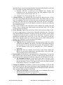
The above command tells the tool that the pin named clk is the clock and that your desired clock period is 5 nanoseconds. We need to set the clock period constraint carefully. If the period is unrealistically small, then the tools will spend forever trying to meet timing and ultimately fail. If the period is too large, then the tools will have no trouble but you will get a very conservative implementation. You could also add additional constraints such as constrain the arrival of certain input signals, the drive strength of the input signals, capacitive load on the output signals etc. Below are some examples. These constraints are defined by you, the user; hence we can call them user specified constraints. Set input constraints by defining how much time would be spent by signals arriving into your design, outside your design with respect to clock. dc_shell-xg-t> set_input_delay 2.0 [remove_from_collection [all_inputs] clk ] –clock ideal_clock1 Similarly you can define output constraints, which define how much time would be spent by signals leaving the design, outside the design, before being captured by the same clk. dc_shell-xg-t> set_output_delay 2.0 [all_outputs] –clock ideal_clock1 Set area constraints: set maximum allowed area to 0 , well it’s just to instruct design compiler to use as less area as possible. dc_shell-xg-t > set_max_area 0 Please refer to tutorial on “Basics of Static Timing Analysis” for more understanding of concepts of STA and for more information on the commands used in STA, please refer to the Primetime Manual and DC Compiler Manual at location /packages/synopsys/ 10. Now we are ready to use the compile command to actually synthesize our design into a gate-level netlist. Two of the most important options for the compile command are the map effort and the area effort. Both of these can be set to one of none, low, medium, or high. They specify how much time to spend on technology mapping and area reduction. dc_shell-xg-t> compile -map_effort medium -area_effort medium DC will attempt to synthesize your design while still meeting the constraints. DC considers two types of constraints: user specified constraints and design rule constraints. We looked at the user specified constraints in the previous step. Design rule constraints are fixed constraints which are specified by the standard cell library. For example, there are restrictions on the loads specific gates can drive and on the transition times of certain pins. To get a better understanding of the standard cell library, please refer to Generic 90nm library documents in the below location which we are using in the tutorial. San Francisco State University Nano-Electronics & Computing Research Lab 52