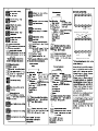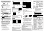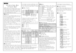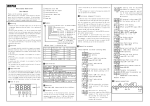
1
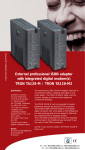
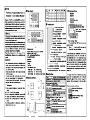
AL2
SV
T h a n k s a l o t f o r s e l e c t i n g MYPIN p r o d u c t s !
Before operating this instrument, please carefully
>
>
electrical shock, fire or malfunction
Use this instrument in the scope of its
specifications. Otherwise fire or malfunction may
result.
! Caution
The
instruments
should
be
installed
to
avoid strong noise resources.If the sign al c ab le i s t oo l on g, we w ou l d su gg es t yo u
Rpm
Lin
⑤
④
⑥
67.5+0.5
67.5+0.5
95
95
72
72
12
100
91+0.5
43.5+0.5
65
① Measured value
12
T:
SCR
R:RELAY
S:SSR/LOGIC
A L 1 :N :N o n
T:
SCR
R:RELAY
T:
SCR
S:SSR/LOGIC
B l a n k :N o n
or
4-20mA
Display
4:4 digit
5:5 digit
4:48H × 96W
6:6 digit
supply:
FA Series
Frequency/Line-speed
and
E:DC
24V
↑
A
ment of dust or flalmable gass.
+
↑
B
D
Measure range
A c c ur ac y
0 . 0 1 HZ -1 0 KH Z
0 . 1 % F . S ± 2d ig i t
Pulse,
Input signals
Insulation
resistance
Operation
environment
F
↑
↑
↑
H
square
wave,5V ≤ H ≤ 30V
0 ≤ L ≤ 2V,up edge contact
Weight
(B e t w e e n p o w e r t e r m i n a l
and the housing)
t e m p e r a t u r e :0 - 5 0 ℃
key for more
Calibration
setting
setting
☆ Rate setting steps:
A :P r e s s << / R s t k e y ,L E D f l a s h e s a n d y o u c a n
B:Press
/
key to modify the numerals
☆ Notice: When the instrument is for measuring frequency, the rate should be set
t o 1 .0 0 0 . W h e n i t i s f o r m e a s u r i n g t e c h o ,
the rate should be set according to concret
applicaiton. When it is for measuring linespeed, the rate should be set according
to the measuring unit/pulse.eg.10 pulse
in perimeter of 1m.then you can setit 110=0.1m.
☆ Display convertion:In displaying state,
press SET to convert.There are 3 data to
display:Hz,Rpm,Lin.The relative lamp will
o n w h e n i t ’s d i s p l a y e d i n t h e l o w L E D .
Alarm
parameter
↓
setting
M e a s u r e d v al u e d i s p l a y
Rate setting
R E L A Y : n o r m a l o p e n 2 5 0 V A C 3 A / 3 0 V D C 3 A C O S ¢= 1
DC 2 4 V / 1 5V
30 m A m a x
AC 1500V 1min
and
than 2 seconds
Alarm
≥ 10K Ω
Withstand voltage ≥ 1 0 0 M Ω (D C 5 0 0 V B e t w e e n p o w e r
strength
terminal and the housing)
↑
G
90-260VAC or 220V 50/60Hz consumption<5VA
0.1-9999,0.1-99999 depend on digits display
0 . 1 - 9 9 9 9 、0 . 1 - 9 9 9 9 9
Alarm
Auxiliary power
↑
C
Tachometer
Display LED
Display range
Inputimpedance
+
8:48H × 96W
Specifications
Power
Mounting and Sizes
7:72H × 72W
↓ Press
C:P r e s s S E T k e y t o c o n f i r m
output:
I :0 - 2 0 m A
Measured value display
Rate setting/Timing setting
shift the digit
Size:
6 、P o w e r f a i l p r o t e c t i o n f o r a t l e a s t 1 0
years
ALL LED ON
4:RS485
B la nk :9 0- 2 60 V A C 5 0/ 6 0H z
+
↓
↓SET > 3S
S:SSR/LOGIC
Power
+
Power ON
100
power:
2:RS232
Analogue
Unit indicator lamps.
E
Auxiliary
R:RELAY
Set value
Shift key
Up key
Down key
3 、U s e h i g h q u a l i t y M I C R O C H I P c o n t r o l C P U
4 、I n p u t a n d o u t p u t i s o p t i c a l i s o l a t e d
48
Self-check
A L 3 :N :N o n
ON: Alarm OFF: No alarm
F/T: on:Frequency,flash:Timer
③ Select/Confirm key
↑
96
Parameter setting
↓
Blank:non
② Output indicator lamp for AL1 and AL2
④
⑤
⑥
⑦
⑧
115
A :1 2 V B :2 4 V
Communication:
⑦
on: Indicate Line-speed,
machine,
80
FA8
Lin/S lamp
7 、W i d e l y a p p l i e d i n c h e m i c a l ,
light industrial etc,,
8
A L 2 :N :N o n
with the power.
T o a vo i d u si n g t he in st r um e nt s i n e n vi r on -
speed
2 、4 , 5 , 6 d i g i t L E D d i s p l a y
48
↑ ↑ ↑
on: Indicate Hz,
on: Indicate Rpm,
1 、C a n m e a s u r e f r e q u e n c y , t e c h o a n d l i n e -
48
<<
<</RST
Hz/H lamp
Rpm/M lamp
★ Features
65
⑧
use shield cables.
Please do not install the signal together
ment of strong shock
or concussion.
T o av oi d us in g t he i ns tr um en t
in e nv ir on -
65
FA □□ - □□□□□□□
Hz
↑
H
<<
when cleaning this instrument. Do not disassemble,
repair or modify the instrument. This may cause
FA
②
Do not wire when the power is on. Do not connect the
unused terminals. Do not turn on the power supply
G
Ordering code
<<
the wiring is completed. Otherwise electrical shock,
fire or malfunction may result.
Lin
↑
Please do not turn on the power supply until all of
F
45+0.5
→
→
→
→
→ AL2
→AL3
③→ SET
E
44.5+0.5
①
AL1
D
<<
tributors whom you buy from. This manual is subject
to change without prior notice.
Warning
Rpm
Hz
/RST
C
FA4
>
>
SET
>
>
F/T
read this manual and fully understand its contents.
If have probroms, please contact our sales or dis-
B
<<
PV
AL1
A
<<
Tachometer I n s t r u c t i o n M a n u a l
Model
FA4
HH4
FA7
HH7
FA8
HH8
↓
Sizes
Name of parts
FA Series Frequency/Line-speed /
↓
MYPIN
humidity: 35-85%RH
FA4(HH4):abt 250g
FA7/FA8(HH7/HH8):atb 350g
↓
SET>3S
A l a r m 1 s e t t i n g ,r a n g e
L S P ≤A L 1 ≤U S P
↓ SET
Low
Bit
setting,
Low
alarm
↓
value:Display
value-Modified
value,range= ± 50.0
Password setting. Range 0-200
LCK=000,Parameter can be
LCK=010,Parameter can be
↓
measurement process
0:0.01-1Hz,will return 0 after
100sec.
1:>1 Hz,will return 0
SET
2-5:Average measuring
display setting.
Password setting:
factory setting is
read
read
for those models with alarm or analogue only.
for
Low
:
frequency/tacho/
accordingly
display
setting,
press
frequency
point setting
,
<<
to
Rate setting
I n
m e a s u r i n g
estate,
press
SET
key, Hz indicator
↓l a m p o n
Measured value display
Rate setting
shift, press
confirm
SET
↓SET
<<
SET key to confirm
Alarm 2 hystersis value setting.
↓ SET
↓
6
5
4
2
1
3
RXD TXD
AL2
★ Diagram for FA with alarms
measurement
process:
with
of
roller
and
belt,circumfer-
roller=0.5cm,sensoris
rotary
encoder with 10 impulses per rotation.
1.Request meter to display frequency
of
roller:modulus=0.1(1/10).
2.Request meter to display tacho of
roller,modulus=impulse per rotation=10.
Tacho=(measureing
value+no.of pulse
per
rotation)*60=(measuring value*60)+10.
3.Request meter to display the speed of
the
unit meter/minute
Modulus=(roller circumference+no.of
press
↓ SET
↓
Device
press SET key to
confirm
Decimal point setting. Press <</RST key
to shift, press
key to modify and
0 :0 . 0 1 t o 1 H z , w i l l r e t u r n “0 ” a f t e r 1 0 0 s e c o n d s
1 :> 1 H z , w i l l r e t u r n “0 ” i n 1 s e c o n d
<<
<<
A l a r m 3 h y s t e r s is v a l u e s e t t i n g .
SET
Frequency
<<
↓ SET
7
ence
SET key to confirm
↓
A l a rm 1 h y s te r s i s v al u e s e t ti n g .
↓ SET
8
key to modify and
Decimal point setting. Press <</RST key
to shift, press
key to modify and
press
10 9
will return
Rate setting
Input signal setting
In measuring estate,
↓ Press and hold
SET key, Lin indikey for
↓press
cator lamp on
more than 3
Measured value display
↓ seconds, press
Rate setting
<</RST k e y t o
key to modify and
press SET key to
key to con firm
90-260V AC
★(If any changed, please refer to the
<<
<<
P re s s << / R S T k e y t o s h i f t , P r e s s
/ key to modify and press SET
↓
↓
1 :> 1 H z ,
“0” in 1 second
<<
shift, press
High display setting for Max
<<
↓
SET
↓SET
more than 3
↓seconds,
<</RST k e y
↓SET Decimal
seconds
↓ setting
Input signal setting
↓Press and hold
key for
AL1
GND Fin
SET key to confirm
<<
line-speed
press
Line-speed measurement
<<
stands
SET
<<
Input signal selection
↓SET
↓
↓
for more than 3 seconds
4~20mA
pro duct sho wing .)
<<
and hold
↓ SET
setting
<<
<<
↓Press
1
220V AC
20 19 18 17 16 15 14 13 12 11
Frequency measurement
setting
<<
Rate
2
3
Decimal point setting. Press <</RST key
to shift, press
key to modify and
015
available for those models with alarm only.
Measured value display
12/24V
Frequency measurement process:
0 :0.01 to 1 Hz, will return “0” after 100
★ Note: The parameters in black color are available
4
↓SET
in 1sec.
value
and write
★ Note: The parameters in black color are
5
★ Diagram for FA without alarms
Rate setting
<<
value=Measured
Measured value display
to
confirm
SET F r e q u e n c y
6
Fin COM
key to modify and
press SET key to
address,
r an ge 0 0 0 -2 0 0 .
alarm
Modified
shift, press
communication
setting
press
<</RST k e y
7
→
High
L:
↓seconds,
Bit/S
8
→
H:
mode
9.6K
10 9
cator lamp on
+
3
setting is
↓
→
Alarm
setting,
↓SET
L S P ≤A L 3 ≤U S P
↓ SET
rate
factory
range
press SET key, RPM indi-
more than 3
<<
3
Rate setting
In measuring estate,
→
↓SET
alarm
Input signal setting
↓Press and hold
key for
→
mode setting
alarm
setting,
,
→
L:
Alarm
↓ SET
value
<<
Alarm 2
H: High
↓ SET
↓ SET
high
20 19 18 17 16 15 14 13 12 11
↓
→
Analogue
range:LSP ≤ trL ≤ USP
SET
setting
↓SET
range
Terminal configurations
Tacho measurement
setting,
→
setting,
L S P ≤A L 2 ≤U S P
↓
value
→
alarm
2
low
range:LSP ≤ trL ≤ USP,
<<
Low
Alarm
Analogue
<<
L:
↓
setting
alarm
<<
↓ SET
mode
<<
/
1
High
<<
H:
SET
belt,eg.the
pulse
per
Frequency measurement process:
linespeed
per
minute,
rotation)=0.0+10=0.05
L i n e s p e e d = m e a s u r i n g
value*modulus*60s=measuring value*0.
05*60=3(Viz.modulus=3)
User can
modulus
set and adjust the value of
according
to
the
real
application.
0 :0.01 to 1 Hz, will return “0” after 100
seconds
1:More than 1 Hz, will return
“0” in 1 second
Press
and hold
key for more
than 3 seconds, it will return to
Press
measuring estate.
measuring estate.
and hold
<<
Alarm
<<
↓SET
key for more
than 3 seconds, it will return to
2