1
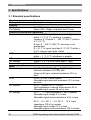
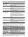
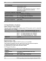
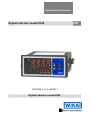
Operating instructions
Digital indicator model DI25
14027536 • V1.6 • 09/2011
Digital indicator model DI25
GB
GB
Operating instructions model DI25 page 1 - 44
© 2010 WIKA Alexander Wiegand SE & Co. KG
All rights reserved.
WIKA® is a registered trademark in various countries.
Prior to starting any work, read the operating instructions!
Keep for later use!
2
WIKA operating instructions digital indicator DI25
Contents
1
2
General information ................................................................................5
Safety .......................................................................................................6
2.1
2.2
2.3
2.4
3
Intended use ........................................................................................6
Personnel qualification.........................................................................8
Special hazards ...................................................................................8
Labelling / Safety marks ......................................................................9
Specifications ........................................................................................10
3.1 Standard specifications......................................................................10
3.2 Specification of options ......................................................................12
3.3 Circuit isolation configuration .............................................................14
4
Design and function ..............................................................................18
4.1 Short description................................................................................18
4.2 Scope of delivery ...............................................................................18
5
Transport, packaging and storage .......................................................19
5.1 Transport ...........................................................................................19
5.2 Packaging..........................................................................................19
5.3 Storage ..............................................................................................19
6
Commissoning, operation ....................................................................20
6.1
6.2
6.3
6.4
Mounting............................................................................................20
Electrical connection ..........................................................................21
Funktions- und Bedienbeschreibung..................................................23
Parameterization/Setup .....................................................................24
6.4.1 Auxiliary function setting mode 2 ................................................. 24
6.4.2 Auxiliary function setting mode 1 ................................................. 25
6.4.3 Alarm setting mode ..................................................................... 25
6.4.4 Actual stored alarm values .......................................................... 26
6.5 Description of parameters ..................................................................26
6.5.1
6.5.2
6.5.3
6.5.4
Auxiliary function setting mode 2 ................................................. 26
Auxiliary function setting mode 2 ................................................. 31
Alarm setting mode ..................................................................... 32
Actual stored alarm values .......................................................... 33
6.6 Functional principle of the setpoints ...................................................34
6.7 Alarm action explanation ...................................................................35
7 Maintenance and cleaning ....................................................................37
7.1 Maintenance ......................................................................................37
WIKA operating instructions digital indicator model DI25
3
7.2 Cleaning............................................................................................ 37
8
9
Faults ..................................................................................................... 37
Dismounting, return and disposal ....................................................... 41
9.1 Dismounting ...................................................................................... 41
9.2 Return ............................................................................................... 41
9.3 Disposal ............................................................................................ 41
10 Appendix: Declaration of conformity .................................................. 42
Declarations of conformity can be found online at www.wika.com.
4
WIKA operating instructions digital indicator DI25
1 General information
1 General information
The instrument described in the operating instructions has been
designed and manufactured using state-of-the-art technology.
All components are subject to stringent quality and environmental
criteria during production. Our management systems are certified to
ISO 9001 and ISO 14001.
These operating instructions contain important information on handling
the instrument. Working safely requires that all safety instructions and
work instructions are observed.
Observe the relevant local accident prevention regulations and general
safety regulations for the instrument's range of use.
The operating instructions are part of the instrument and must be kept
in the immediate vicinity of the instrument and readily accessible to
skilled personnel at any time.
Skilled personnel must have carefully read and understood the
operating instructions, prior to beginning any work.
The manufacturer's liability is void in the case of any damage caused by
using the product contrary to its intended use, non-compliance with
these operating instructions, assignment of insufficiently qualified skilled
personnel or unauthorised modifications to the instrument.
The general terms and conditions, contained in the sales
documentation, shall apply.
Subject to technical modifications.
Further information:
- Internet address:
- Relevant data sheet:
- Application consultant:
www.wika.de / www.wika.com
AC 80.02
Tel.: (+49) 9372/132-0
Fax: (+49) 9372/132-406
E-Mail: [email protected]
WIKA operating instructions digital indicator model DI25
5
2 Safety
Explanation of symbols
WARNING!
... indicates a potentially dangerous situation that can result
in serious injury or death, if not avoided.
Information
... points out useful tips, recommendations and information
for efficient and trouble-free operation.
DANGER!
...identifies hazards caused by electric power. Should the
safety instructions not be observed, there is a risk of serious
or fatal injury.
2 Safety
WARNING!
Before installation, commissioning and operation, ensure that
the appropriate instrument has been selected in terms of
measuring range, design and specific measuring conditions.
Non-observance can result in serious injury and/or damage
to equipment.
Further important safety instructions can be found in the
individual chapters of these operating instructions.
2.1 Intended use
The device is designed for the evaluation and display of current loop signals.
With the setpoints, it is possible to perform simple control tasks (only possible
for devices with setpoints).
The instrument has been designed and built solely for the intended use
described here, and may only be used accordingly.
6
WIKA operating instructions digital indicator DI25
2 Safety
Please read the following safety advice and the assembly before installation
and keep it for future reference.
If the instrument is transported from a cold into a warm environment, the
formation of condensation may result in the instrument malfunctioning. Before
putting it back into operation, wait for the instrument temperature and the
room temperature to equalise.
Notes on installation
There must be no magnetic or electric fields in the vicinity of the device,
e.g. due to transformers, mobile phones or electrostatic discharge.
Do not install inductive consumers (relays, solenoid valves etc.) near
the device and suppress any interference with the aid of RC spark
extinguishing combinations or free-wheeling diodes.
Keep input, output and supply lines separate from one another and do
not lay them parallel with each other. Position “go” and “return lines”
next to one another. Where possible use twisted pair. So, you receive
best measuring results.
Screen off and twist sensor lines. Do not lay current-carrying lines in the
vicinity. Connect the screening on one side on a suitable potential
equaliser (normally signal ground).
The device is not suitable for installation in areas where there is a risk
of explosion.
Any electrical connection deviating from the connection diagram can
endanger human life and/or can destroy the equipment.
The terminal area of the devices is part of the service. Here electrostatic
discharge needs to be avoided. Attention! High voltages can cause
dangerous body currents.
Galvanic insulated potentials within one complex need to be placed on
a appropriate point (normally earth or machines ground). So, a lower
disturbance sensibility against impacted energy can be reached and
dangerous potentials, that can occur on long lines or due to faulty
wiring, can be avoided.
The manufacturer shall not be liable for claims of any type based on
operation contrary to the intended use.
WIKA operating instructions digital indicator model DI25
7
2 Safety
2.2 Personnel qualification
WARNING!
Risk of injury should qualification be insufficient!
Improper handling can result in considerable injury and
damage to equipment.
The activities described in these operating instructions
may only be carried out by skilled personnel who have
the qualifications described below.
Keep unqualified personnel away from hazardous areas.
Skilled electrical personnel
Skilled electrical personnel are understood to be personnel who, based on
their technical training, knowledge of measurement and control technology
and on their experience and knowledge of country-specific regulations,
current standards and directives, are capable of carrying out work on
electrical systems and independently recognising and avoiding potential
hazards.
The skilled electrical personnel have been specifically trained for the work
environment they are working in and know the relevant standards and
regulations.
The skilled electrical personnel must comply with current legal accident
prevention regulations.
2.3 Special hazards
DANGER!
Danger of death caused by electric current.
Upon contact with live parts, there is a direct danger of
death.
Electrical instruments may only be installed and mounted
by skilled electrical personnel.
Operation using a defective power supply unit (e.g. short
circuit from the mains voltage to the output voltage) can
result in life-threatening voltages at the instrument!
WARNING!
Do NOT use this product as safety or emergency stopping
device, or in any other application where failure of the
product could result in personal injury or material damage.
Failure to comply with these instructions could result in
death or serious injury and material damage.
8
WIKA operating instructions digital indicator DI25
2 Safety
2.4 Labelling / Safety marks
Product label
Explanation of symbols
Before mounting and commissioning the instrument, ensure
you read the operating instructions!
CE, Communauté Européenne
Instruments bearing this mark comply with the relevant
European directives.
WIKA operating instructions digital indicator model DI25
9
3 Specifications
3 Specifications
3.1 Standard specifications
Mounting method
Control panel
Setting method:
Input system using membrane sheet key
Display
PV display:
Red LED, 4 digits, character size 16 mm
SV-Display:
Green LED, 4 digits, character size 10 mm
Accuracy (Setting and Indication)
Thermocouple:
Within ± 0.2 % of each input span ±1digit or
within ± 2 °C (4 °F), whatever is greater.
However R, S inputs 0 ... 200 °C (400 °F):within ±
6 °C (12 °F)
B input 0 ... 300 °C (600 °F): accuracy is not
guaranteed.
K, J, E, T, N inputs less than 0 °C (32 °F):within ±
0.4 % of each input span ±1digit
RTD:
Within ±0.1 % of each input span ± 1digit, or
within ± 1 °C (2 °F) whichever is greater
DC current:
Within ± 0.2 % of each input span ± 1digit
DC voltage:
Within ± 0.2 % of each input span ± 1digit
Input sampling period:
0.25 seconds
Input
Thermocouple:
K, J, R, S, B, E, T, N, PL- , C (W/Re5-26),
external resistance 100 Ω or less
(However B input: external resistance 40 Ω or
less)
RTD:
Pt100, JPt100, 3-wire system
Allowable input lead wire resistance 10 Ω or less
per wire
DC current:
DC 0 ... 20 mA, DC 4 ... 20 mA
Input impedance: external shunt resistor 50 Ω
Allowable input current 50 mA or less
DC voltage:
DC 0 ... 1 V input impedance 1 MΩ or greater
Allowable input voltage 5 V or less
Allowable signal source resistance 2 kΩ or less
DC 0 ... 5 V, DC 1 ... 5 V, DC 0 ... 10 V input
impedance 100 kΩ or greater
Allowable input voltage 15 V or less
Allowable signal source resistance 100 Ω or less
10
WIKA operating instructions digital indicator DI25
3 Specifications
Alarm output A1, A2
The alarm action can be of No alarm action, High limit alarm, Low limit
selected out of:
alarm, High limit alarm with standby and Low limit
alarm with standby.
Action:
ON/OFF action
Hysteresis:
0.1 ... 100.0 °C (°F) or 1 to 1000
(The placement of the decimal point follows the
selection)
Output:
Relay contact 1a
Control capacity 3 A, AC 250 V (resistive load)
Electric life 100,000 times
Alarm output A3
The alarm action can
No alarm action, High limit alarm, Low limit alarm,
be selected out of
High limit alarm with standby, Low limit alarm with
standby and High/Low limit range alarm.
However High/Low limit range alarm can only be
selected, when A1 High limit alarm (High limit
alarm with standby) and A2 Low limit alarm (Low
limit alarm with standby) are combined, or vice
versa.
Action:
ON/OFF action
Hysteresis:
0.1 ... 100.0 °C (°F) or 1 ... 1000
(The placement of the decimal point follows the
selection)
Output:
Relay contact 1a
Control capacity 3 A, AC 250 V (resistive load)
Electric life 100,000 times
Analogue signal output (transmission output) 4 ... 20 mA
The input value is converted in analog every 0.25 seconds and is outputted
in DC current.
When using the transmission output as an input for other instruments,
check that the input impedance of these instruments is smaller than the
maximum load resistance of the transmission output.
Resolution:
1/12000
DC current:
DC 4 ... 20 mA (load resistance max. 500 Ω)
Output accuracy:
Within ± 0.3 % of output span
Power supply
AC 100 ... 240 V 50/60 Hz or
AC/DC 24 V 50/60 Hz
Allowable voltage
for AC 100 ... 240V: AC 85 ... 264 V
fluctuation range
for AC/DC 24V: AC/DC 20 ... 28 V
Power consumption:
Approx. 10 VA
Storage
Configuration is stored in a nonvolatile storage
WIKA operating instructions digital indicator model DI25
11
3 Specifications
CE-Conformity
2004/108/EG (EMV)
2006/95/EG (LVD)
EN 61326-1:2006 (Emission for group 1, class A,
Immunity for industrial environments)
EN 61010-1:2010
Permissible ambient conditions
Ambient temperature:
0 ... 50 °C (32 ... 122 °F)
Storage temperature:
-20 … +50 °C (-4 ... 122 °F)
Ambient humidity:
35 ... 85 % RH (non-condensing)
Mass:
approx. 300 g
External dimensions:
96 x 48 x 100 mm (w x h x d)
Dust-proof/Drip-proof:
IP66 (front)
Material:
Flame resistant resin (case)
3.2 Specification of options
Other analogue output signals
The input value is converted in analog every 0.25 seconds, and it is outputted
in DC current or DC voltage.
DC current:
DC 0 ... 20 mA (load resistance max. 500 Ω)
DC voltage:
DC 0 ... 1 V (load resistance min. 100 kΩ)
DC 0 ... 5 V (load resistance min. 500 kΩ)
DC 1 ... 5 V (load resistance min. 500 kΩ)
DC 0 ... 10 V (load resistance min. 1 MΩ)
Resolution:
1/12000
Output accuracy:
Within ± 0.3 % of output span
Digital interface: [C5]
When this option is added, HOLD function is not available.
The following operations can be carried out from the external computer.
(1) Reading and setting of the various setting values
(2) Reading of the input value and action status
(3) Change of functions
Communication
interface:
Communication
method:
Data transfer rate
Parity:
12
Based on EIA RS-485
Half-duplex communication start stop
synchronous
2400, 4800, 9600, 19200 bps
Even, Odd and No parity
WIKA operating instructions digital indicator DI25
3 Specifications
Stop bit:
Communication
protocol:
Connectable number of
units:
Communication error
detection:
Communication
protocol
Start bit
Data bit
Parity
1, 2
WIKA protocol, Modbus RTU, Modbus ASCII
Maximum 31 units to 1 host computer
Double detection by parity and checksum
WIKA protocol
Modbus ASCII
Modbus RTU
1
7
even
1
7
Selectable
(even)
selectable (1)
1
8
Selectable
(no)
selectable (1)
Stop bit
1
(x) Basic setting value
Data bit is automatically selected upon selecting the communication protocol.
Transmitter supply [P24]
Output voltage
24 ± DC 3 V (when load current is 30 mA)
Ripple voltage
Within 200 mV (when load current is 30 mA)
Maximum load current
30 mA
Terminal cover [K]
Electrical shock protecting terminal cover
WIKA operating instructions digital indicator model DI25
13
3 Specifications
3.3 Circuit isolation configuration
Ground terminal
Isolated
Power supply
Isolated
Isolated
A1 output
CPU
Isolated
Nonisolated
A2 output or
Isolated power
output
Isolated
Isolated
HOLD input
Isolated
Communication
Transmission
output
Input
Isolated
A3 output
Isolation resistance:
Dielectric strength:
Isolated
10 MΩ or greater at DC 500 V
AC 1.5 kV for 1minute between input terminal and
ground terminal
AC 1.5 kV for 1minute between input terminal and
power terminal
AC 1.5 kV for 1minute between power terminal
and ground terminal
AC 1.5 kV for 1minute between output terminal
and ground terminal
AC 1.5 kV for 1minute between output terminal
and power terminal
Output terminal comprises A1, A2 and A3 output
terminals, transmission output terminal and
communication terminal.
For further specifications see WIKA data sheet AC80.02 and the order
documentation.
14
WIKA operating instructions digital indicator DI25
3 Specifications
Model name and order code
DI25 Input
Power
supply
MM
Multi-range (*1)
AC 100...240 V, 50...60
Hz
AC/DC 24 V
3 alarm outputs for
process value monitoring
H
L
Output
configuration
3AS
(*2)
P24
Analogue
signal output
Digital interface
Terminal cover
Colour of the case
Instrument configuration
Additional text
*1
*2
*3
A
B
V
G
K
W
ZZ
C5
Transmitter power supply
and 2 alarm outputs (*2)
4 ... 20 mA
0 ... 20 mA
0 ... 1 V
0 ... 5 V
1 ... 5 V
0 .... 10 V
without
RS-485 (*3)
Z
ohne
K
Electrical shock
protecting cover
B
black
B
Factory adjustment
K
Customer specific
configuration
Z without
T Additional text
The input type can be selected out of thermocouple (10 types), RTD
(2 types), DC current (2 types)
and DC voltage (4 types) by key operation.
Alarm actions (5 types and No alarm action) and Energized/
Deenergized can be selected by key operation.
If the option digital interface is added, HOLD function is not available.
WIKA operating instructions digital indicator model DI25
15
3 Specifications
Dimensions
Terminal cover
96
11.5
2 (1)
48
44.5
Gasket
98.5
104.5 (1)
106.2
Operating elements
(10)
(13)
(12)
(6)
(7)
(8)
(9)
(11)
(1)
(2)
No. Name
(1) PV
Display for actual
value
(2) SV
Display for setting
valuess
(3) A1
A1 indicator
(4)
A2
A2 indicator
(5)
A3
A3 indicator
(6)
HOLD HOLD indicator
(7)
A1
A1 setting indicator
(8)
A2
A2 setting indicator
(9)
A3
A3 setting indicator
16
(3) (4) (5)
Description
Indicates the input value with a red
LED.
Indicates the setting value with a
green LED.
When A1 output is ON, a red LED
lights up.
When A2 output is ON, a red LED
lights up
When A3 output is ON, a red LED
lights up.
When PV HOLD (Hold, Peak hold,
Bottom hold) output is ON, a yellow
LED lights up.
When A1 setting is indicated, a green
LED lights up
When A2 setting is indicated, a green
LED lights up.
When A3 setting is indicated, a green
WIKA operating instructions digital indicator DI25
3 Specifications
(10)
-key
(11)
(12)
-key
MODE key
(13)
FAST key
LED lights up.
Increases the numeric setting value
Decreases the numeric setting value
Selects the setting mode or registers
the setting value.
(To register the setting value or
selected value, press the MODE key)
Makes the setting value change faster
while holding down Increase or
Decrease key together
WIKA operating instructions digital indicator model DI25
17
4 Design and function
4 Design and function
4.1 Short description
The digital indicator DI25 is a competitively-priced, multifunction instrument
for a wide variety of measuring tasks. The multi-function input has 18 different
input configurations, which can be selected via the rear connections and also
by selection the appropriate input signal with in the instrument configuration.
In this way it is possible to connect transmitters with current or voltage
signals, and both resistance thermometers or thermocouples to the same
instrument.
The measured value can be retransmitted for further processing via an
analogue 4 ... 20 mA output (standard) or via an RS-485 Serial Interface
(optional). Other analogue retransmission signals are also available as
option.
The basic version of the DI25 indicator features three alarm outputs.
Instruments with the optional 24 V transmitter power supply have two alarm
outputs available.
With the high ingress protection of the fascia (IP66) the digital indicator DI25
can also be used under extreme operating conditions. All configuration and
programming can be done using the front control keys.
4.2 Scope of delivery
The scope of delivery is:
Indicator
2 fixing elements
Seal
Operating instructions
Cross-check scope of delivery with delivery note.
18
WIKA operating instructions digital indicator DI25
5 Transport, packaging and storage
5 Transport, packaging and storage
5.1 Transport
Check instrument for any damage that may have been caused by transport.
Obvious damage must be reported immediately.
5.2 Packaging
Do not remove packaging until just before mounting. Keep the packaging as it
will provide optimum protection during transport (e.g. change in installation
site, sending for repair).
5.3 Storage
Permissible conditions at the place of storage:
Storage temperature: -20 ... +50 °C
Humidity: 35 ... 80 % relative humidity (no condensation)
Avoid exposure to the following factors:
Direct sunlight or proximity to hot objects
Mechanical vibration, mechanical shock (putting it down hard)
Soot, vapour, dust and corrosive gases
Potentially explosive environments, flammable atmospheres
Store the instrument in its original packaging in a location that fulfils the
conditions listed above. If the original packaging is not available, pack and
store the instrument as described below:
1. Wrap the instrument in an antistatic plastic film.
2. Place the instrument, along with shock-absorbent material, in the
packaging.
3. If stored for a prolonged period of time (more than 30 days), place a
bag, containing a desiccant, inside the packaging.
WARNING!
Before storing the instrument (following operation), remove
any residual media. This is of particular importance if the
medium is hazardous to health, e.g. caustic, toxic,
carcinogenic, radioactive, etc.
WIKA operating instructions digital indicator model DI25
19
6 Commissoning, operation
6 Commissoning, operation
Please read the safety instructions and installation instructions in chapter 2
before installation and keep this user manual for future reference.
6.1 Mounting
Mount the instrument into a vertical panel to fulfill the Dust-proof/Drip-proof
specification (IP66).
1. Insert the instrument from the front side of the panel.
2. Attach the screw type mounting brackets by the holes on the sides of
the case and fix the instrument in place with the screws.
Mountable panel thickness: within 1 to 15 mm
WARNING:
20
As the case is made of resin, do not use excessive force
while screwing in the mounting bracket, or the case or
screw type mounting bracket could be damaged. The
torque is approximately 0.12 Nm.
WIKA operating instructions digital indicator DI25
6 Commissoning, operation
6.2 Electrical connection
POWER SUPPLY
24 V AC/DC
24 V DC
30 mA
P24
A2
3A
250 V
AC
9
20
8
7
3A
250 V
AC
NO
DC mA
DC V
RTD B
TC
TRANSMIT
OUTPUT
A1
10
5
4
3
2
1
(shunt resistor)
A
19
6
GND
NO
50 Ω
B
3
2
POWER SUPPLY
100 to 240 V AC
18
SG
17
YB(+)
HOLD
16
15
RS-485
14
Ya(-)
A3
13
3A
250 V
AC
12
11
NO
WARNING!
Turn the power supply to the instrument off before wiring or
checking it.
Working or touching the terminal with the power switched on
may result in Electric Shock causing severe injury or death.
Name
A1, A2, A3
TRANSMIT OUTPUT
P24
HOLD
RS-485
TC
RTD
DC V
DC mA
Description
Alarm output 1, 2, 3
Analogue signal output
Transmitter supply
HOLD function
Serial communication (RS-485)
Thermocouple
Resistance temperature detector
DC voltage
DC current (Shunt resistor: 50 Ω, necessary for
input signals DC current)
(Dotted lines show options
WIKA operating instructions digital indicator model DI25
21
6 Commissoning, operation
Hint
The terminal block of the DI25 is designed to be wired from
the upper side. The lead wire must be inserted from the
upper side of the terminal, and fastened by the terminal
screw.
Use a thermocouple and compensating lead wire according
to the sensor input specification of this instrument.
Use the 3-wire RTD which corresponds to the input
specification of this instrument.
This instrument does not have built-in power switch, circuit
breaker or fuse. Therefore, it is necessary to install them in
the circuit near the external instrument. (Recommended fuse:
Time-lag fuse, rated voltage AC 250 V, rated current 2 A)
When using a AC/DC 24 V for the power source, do not
confuse the polarity when it is DC.
When using a relay contact output type, externally use a relay
according to the capacity of the load to protect the built-in
relay contact.
When wiring, keep input wires (thermocouple, RTD, etc.)
away from AC sources or load wires to avoid external
interference.
Do not apply a commercial power source to the sensor
connected to the input terminal nor allow the power source to
come into contact with the sensor.
y-Type
Round type
22
Tightening
torque
0,6 Nm
Max. 1,0 Nm
3,2mm
5,8mm oder
weniger
terminal
5.8mm oder
weniger
Use a solderless terminal with isolation sleeve that fits in the M3 screw as
shown below.
3,2mm
WIKA operating instructions digital indicator DI25
6 Commissoning, operation
6.3 Funktions- und Bedienbeschreibung
First wire the power terminals only. After the power is turned on, the sensor
input characters and temperature unit are indicated on the PV display and the
input range high limit value is indicated on the SV display for approx. 3
seconds.
During this time, all outputs and the LED indicators are in OFF status.
Indication will then start and the input value will be indicated on the PV
display and alarm setting value will be indicated on the SV display.
Chose the setting values, referring to chapter “Parameterization/Setup”.
After this, turn off the power supply and connect sensor, TC or RTD. When
finished wiring, turn on the power supply.
Possible input configurations
Sensorinput
°C
PV-Display
SV-Display
K
°F
PV-Display
SV-Display
J
R
S
B
E
T
N
PLC (W/Re5-26)
Pt100
JPt100
DC 4 ...
20mA
DC 0 ...
20mA
DC 0 ... 1V
DC 0 ... 5V
DC 1 ... 5V
DC 0 ... 10V
Scaling high limit value
WIKA operating instructions digital indicator model DI25
23
6 Commissoning, operation
Hint
For input configuration DC 4 ... 20 mA or DC 0 ... 20 mA the 50
Ω shunt resistor has to be connected to terminals 18 and 19.
6.4 Parameterization/Setup
The indicators configuration is done in four different menu levels:
Auxiliary function setting mode 2
Configuration of input, of alarm
settings and analog output signal
Auxiliary function setting mode 1: Configuration of lock mode, sensor
correction and serial interface
Alarm setting mode:
Configuration of alarm values
Actual stored alarm values
Indication of actual stored alarm
values
6.4.1 Auxiliary function setting mode 2
To configure the auxiliary function setting mode 2, press first “ +
then additionally the “MODE” key for 3 seconds.
To reach the next parameter, press “MODE” key.
Display
Meaning
[
]
Input type selection
[
]
Scaling high limit setting
[
]
Scaling low limit setting
[
]
Decimal point place selection
[
]
PV filter time constantsetting
[
]
A1 action selection
[
]
A2 action selection
[
]
A3 action selection
A1 Energized/Deenergized selection
[
]
A2 Energized/Deenergized selection
[
]
A3 Energized/Deenergized selection
[
]
A1 hysteresis setting
[
]
A2 hysteresis setting
[
]
A3 hysteresis setting
[
]
A1 action delayed timer setting
[
]
A2 action delayed timer setting
[
]
A3 action delayed timer setting
[
]
Transmission output high limit setting
[
]
Transmission output low limit setting
[
24
key” and
*
]
*
*
*
WIKA operating instructions digital indicator DI25
6 Commissoning, operation
Display
Meaning
[
]
HOLD function selection
*
After configuration of the last parameter you leave the menu with the „MODE“
key.
*: Parameters marked with a “ * “ show options, which are effective only when
the options are designated.
If the option digital interface [C5] is applied, the setting item “HOLD function
selection” is not indicated.
6.4.2 Auxiliary function setting mode 1
To configure the auxiliary function setting mode 1, press first “ key” and
then additionally the “MODE” key for 3 seconds.
To reach the next parameter, press “MODE” key.
Display
Meaning
[
]
Setting value lock designation
[
]
Sensor correction setting
[
]
Communication protocol selection
*
[
]
Instrument number selection
*
[
]
Data transfer rate selection
*
[
]
Parity selection
*
[
]
Stop bit selection
*
After configuration of the last parameter you leave the menu with the „MODE“
key.
*: Parameters marked with a “ * “ show options, which are effective only when
the options are designated.
6.4.3 Alarm setting mode
To configure the auxiliary function setting mode 1, press “MODE” key.
To reach the next parameter, press “MODE” key.
Display
Meaning
[
]
A1 alarm value setting
[
]
A2 alarm value setting
[
]
A3 alarm value setting
After configuration of the last parameter you leave the menu with the „MODE“
key.
WIKA operating instructions digital indicator model DI25
25
6 Commissoning, operation
6.4.4 Actual stored alarm values
To display the actual stored alarm values during operation/process, “
and the “MODE” key.
To reach the next parameter, press again “ key” and “MODE” key.
Display
Meaning
*
A1 setting value is indicated
*
A2 setting value is indicated
*
A3 setting value is indicated
*: actual stored alarm value is indicated
key”
6.5 Description of parameters
6.5.1 Auxiliary function setting mode 2
Symbol
26
Name, Function, Range
Default value
Input type selection
Typ K
The input type can be selected from thermocouple
(–200 ... +1370°C)
(10 types), RTD (2 types), DC current (2 types) and
DC voltage (4 types), and the unit °C/°F can be
selected as well.
When changing the input from DC voltage to other
inputs, remove the sensor connected to this
instrument first, then change the input type. If the
input is changed with the sensor connected, the
input circuit may be broken.
TCs & RTDs
°C
°F
K
–200 ... +1370 °C
–320 ... +2500 °F
–199.9 ... +400.0 °C
–199.9...+750.0 °F
J
–200 ... +1000 °C
–320 ... +1800 °F
R
0 ... 1760 °C
0 ... 3200 °F
S
0 ... 1760 °C
0 ... 3200 °F
B
0 ... 1820 °C
0 ... 3300 °F
E
–200 ... +800 °C
–320 ... +1500 °F
T
–199.9 ... +400.0 °C
–199.9...+750.0 °F
N
–200 ... +1300 °C
–320 ... +2300 °F
PL-II
0 ... 1390 °C
0 ... 2500 °F
C (W/Re5-26) 0 ... 2315 °C
0 ... 4200 °F
Pt100
–199.9 ... +850.0 °C
–199.9...+999.9 °F
JPt100
–199.9 ... +500.0 °C
–199.9...+900.0 °F
Pt100
–200 ... +850 °C
–300...+1500 °F
JPt100
–200 ... +500 °C
–300 ... +900 °F
Current and voltage signals
Notice:
DC 4...20mA –1999 ... 9999
At input configuration 4 ... 20
DC 0...20mA –1999 ... 9999
mA or 0 ... 20 mA it’s
DC 0 ... 1V
–1999 ... 9999
essential to connect the
DC 0 ... 5V
–1999 ... 9999
provided 50Ω measuring
DC 1 ... 5V
–1999 ... 9999
shunt to the terminals 18 and
DC 0 ... 10V
–1999 ... 9999
19.
WIKA operating instructions digital indicator DI25
6 Commissoning, operation
Symbol
Name, Function, Range
Scaling high limit value
Sets scaling high limit value.
Setting range: Scaling low limit value to input range
high limit value
Available only for DC inputs
Scaling lowh limit value
Sets scaling low limit value.
Setting range: Scaling low limit value to input range
high limit value
Available only for DC inputs
Decimal point place selection
Selects decimal point place
No decimal point:
1 digit after decimal point:
2 digit after decimal point:
3 digit after decimal point:
Available only for DC inputs
PV filter time constant setting
Sets PV filter time constant. (If the value is set too
large, it affects alarm action due to the delay of
response)
Setting range: 0.0 to 10.0 seconds
A1 action selection
Selects an action for A1
no alarm action:
high limit alarm:
low limit alarm
high limit alarm with standby:
low limit alarm with standby:
A2 action selection
Selects an action for A1
no alarm action:
high limit alarm:
low limit alarm
high limit alarm with standby:
low limit alarm with standby:
Not available if the option Transmitter supply [P24]
is added
A3 action selection
Selects an action for A1
no alarm action:
high limit alarm:
low limit alarm
high limit alarm with standby:
low limit alarm with standby:
high/low limit range alarm:
High/Low limit range alarm is activated depending
on A1 and A2 setting values. If both A1 and A2 are
turned OFF, A3 is turned ON in combination with
A1 High limit alarm (High limit alarm with standby)
and A2 Low limit alarm (Low limit alarm with
standby) or in combination with A1 Low limit alarm
(Low limit alarm with standby) and A2 High limit
alarm (High limit alarm with standby).
WIKA operating instructions digital indicator model DI25
Default value
9999
–1999
No decimal point
0.0 seconds
No alarm action
No alarm action
No alarm action
27
6 Commissoning, operation
Symbol
28
Name, Function, Range
If High/Low limit range alarm is selected, A3
related setting items (A3 setting, A3 action
Energized / Deenergized selection, A3 hysteresis
setting, A3 action delayed timer setting) are not
available.)
A1 action Energized / Deenergized selection
Selects Energized / Deenergized for A1.
Energized:
Deenergized:
Not available if No alarm action is selected in A1
action selection
A2 action Energized / Deenergized selection
Selects Energized / Deenergized for A2.
Energized:
Deenergized:
Not available if No alarm action is selected in A1
action selection or if the option Transmitter supply
[P24] is added.
A3 action Energized / Deenergized selection
Selects Energized / Deenergized for A3.
Energized:
Deenergized:
Not available if No alarm action is selected in A1
action selection or if high/low limit range alarm
action is selected in A3 action selection.
A1 hysteresis setting
Sets hysteresis for A1
Setting range: 0.1 to 100.0 °C (°F) or 1 to 1000
Not available if no alarm action is selected in A1
action selection
A2 hysteresis setting
Sets hysteresis for A2
Setting range: 0.1 to 100.0 °C (°F) or 1 to 1000
Not available if no alarm action is selected in A2
action selection selection or if the option
Transmitter supply [P24] is added
A3 hysteresis setting
Sets hysteresis for A3
Setting range: 0.1 to 100.0 °C (°F) or 1 to 1000
Not available if no alarm action is selected in A3
action selection or if High/Low limit range alarm is
selected
A1 action delayed timer setting
Sets action delayed timer for A1.When setting time
has passed after the input enters the alarm output
range, the alarm is activated
Not available if No alarm action is selected in A1
action selection
Setting range: 0 to 9999 seconds
A2 action delayed timer setting
Sets action delayed timer for A2.When setting time
has passed after the input enters the alarm output
range, the alarm is activated.
Setting range: 0 to 9999 seconds
Not available if the option Transmitter supply [P24]
Default value
Energized
Energized
Energized
1.0 °C
1.0 °C
1.0 °C
0 seconds
0 seconds
WIKA operating instructions digital indicator DI25
6 Commissoning, operation
Symbol
Name, Function, Range
is added or if No alarm action is selected in A2
action selection
A3 action delayed timer setting
Sets action delayed timer for A3.When setting time
has passed after the input enters the alarm output
range, the alarm is activated.
Setting range: 0 to 9999 seconds
Not available if No alarm action is selected in A3
action selection or if High/Low limit range alarm is
selected.
Transmission output high limit setting
Sets the transmission output high limit value. The
value to be set is that when DC 20 mA is outputted
in standard specification. However, when the
optional Transmission output is added, the value to
be set is that when high limit value of the added
option range is outputted.
Setting range: Transmission output low limit value
to input range high limit value
Transmission output low limit setting
Sets the transmission output low limit value. The
value to be set is that when DC 4 mA is outputted
in standard specification. However, when the
optional Transmission output is added, the value to
be set is that when low limit value of the added
option range is outputted.
Setting range: input range low limit value to
transmission output high limit value
HOLD function selection
Not available if the option Serial communication is
added
3 types of HOLD function can be selected.
HOLD:
(PV at that time is being held and indicated)
Peak HOLD:
(The renewed maximum PV is indicated)
Bottom HOLD:
(The renewed minimum PV is indicated)
How to use HOLD function
Connect terminals 14 and 17 to use HOLD
function. If the terminals are disconnected, the hold
value is deleted and the display shows the regular
measured value.
WIKA operating instructions digital indicator model DI25
Default value
0 seconds
1370 °C
–200 °C
HOLD
29
6 Commissoning, operation
Indication range with DC current and voltage inputs
[Scaling low limit value – Scaling span x 1 %] to [Scaling high limit value
+Scaling span x 10 %]
If the input value exceeds the range -1999 ... 9999, the PV display flashes
also “
” or “
”, even if the real indication range according to the
definition is not yet exceeded.
[Automatic cold junction temperature compensation]
(Only thermocouple input type)
This detects the temperature at the connecting terminal between the
thermocouple and the instrument and always keeps it set to the same status
as when the reference junction is located at 0 °C (32 °F).
[HOLD function]
The following HOLD functions can be selected by the key operation.
HOLD:
By connecting terminals 14 and 17, PV at that time is
being held and indicated.
Peak HOLD:
By connecting terminals 14 and 17, the renewed
maximum PV is indicated.
Bottom HOLD:
By connecting terminals 14 and 17, the renewed
minimum PV is indicated.
Sensor correction function
This corrects the input value from the sensor. When a sensor cannot be set at
a location where control is desired, the sensor measuring temperature may
deviate from the temperature in the controlled location. When controlling with
plural indicators, sometimes the measured temperatures (input value) do not
concur with the same setting value due to difference in sensor accuracy or
dispersion of load capacities. In such a case, the control can be set at the
desired temperature by adjusting the input value of sensors.
30
WIKA operating instructions digital indicator DI25
6 Commissoning, operation
6.5.2 Auxiliary function setting mode 2
Symbol
Name, Function, Range
Setting value lock designation
Locks the setting values to prevent setting
errors. The setting item to be locked
depends on the designation.
(Unlock):
All setting values can be changed.
(Lock 1):
None of the setting values can be
changed.
(Lock 2):
Only main setting value can be
changed.
(Lock 3):
All setting values can be changed.
However, do not change the setting
items in the Auxiliary function
setting mode 2. They return to their
former value after power is turned
off because they are not saved in
the non-volatile memory.
Sensor correction setting
Sets the correction value for the sensor
Setting range: –100,0 to 100,0 °C (°F)
or –1000 to 1000
Communication protocol selection
Selects the communication protocol
WIKA-Protocoll:
Modbus ASCII:
Modbus RTU:
Available only when the option digital
interface [C5] is applied.
Instrument number setting
Sets the instrument number individually
to each instrument when
communicating by connecting plural
instruments in serial communication.
Setting range: 0 to 95
Available only when the option digital
interface [C5] is applied
Data transfer rate selection
Selects a transfer rate to meet of the
host computer.
WIKA operating instructions digital indicator model DI25
Default value
unlock
0.0 °C
WIKA protocol
0
9600bps
31
6 Commissoning, operation
Symbol
Name, Function, Range
2400 bps:
4800 bps:
9600 bps:
19200 bps:
Available only when the option digital
interface [C5] is applied.
Parity selection
Selects the parity.
No parity:
even parity:
odd parity:
Not available when the option digital
interface [C5] is not applied or when
WIKA protocol is selected in the
communication protocol selection.
Stop bit selection
Selects the stop bit.
Setting rate: 1, 2
Not available when the option digital
interface [C5] is not applied or when
WIKA protocol is selected in the
communication protocol selection.
Default value
even
1
6.5.3 Alarm setting mode
Symbol
[
]
[
]
[
]
32
Name, Function, Range
Alarm settings A1
Sets A1 output action point.
Not available if No alarm action is
selected in A1 action selection.
Refer to table „setting range of alarm
action types”.
Alarm settings A2
Sets A2 output action point.
Not available if No alarm action is
selected in A2 action selection or if the
option Transmitter supply [P24] is
applied.
Refer to table „setting range of alarm
action types”.
Alarm settings A3
Sets A3 output action point.
Default value
0 °C
0 °C
0 °C
WIKA operating instructions digital indicator DI25
6 Commissoning, operation
Not available if No alarm action is
selected in A3 action selection.
Refer to table „setting range of alarm
action types”.
Setting range of alarm action types
Alarm action type
Setting range
High limit alarm
Input range low limit to input range high limit value
Low limit alarm
Input range low limit to input range high limit value
High limit alarm with Input range low limit to input range high limit value
standby
Low limit alarm with Input range low limit to input range high limit value
standby
High/Low limit range none
alarm *1
*1: High/Low limit range alarm is available only for A3. If High/Low limit
range alarm is selected, the setting items which are related to A3 (A3
setting, A3 action Energized/Deenergized selection, A3 hysteresis
setting, A3 action delayed timer setting) will not be indicated.
6.5.4 Actual stored alarm values
Name, Function
A1 setting value indication
A1 setting value is indicated on the SV display and A1
setting indicator lights up.
Not available if No alarm action is selected in A1 action
selection.
A2 setting value indication
A2 setting value is indicated on the SV display and A2
setting indicator lights up.
Not available if the option Transmitter supply [P24] is
applied, or if No alarm action is selected in A2 action
selection
A3 setting value indication
A3 setting value is indicated on the SV display and A3
setting indicator lights up.
Not available if No alarm action is selected in A3 action
selection, or if High/Low limit range alarm is selected.
WIKA operating instructions digital indicator model DI25
Default value
0 °C
0 °C
0 °C
33
6 Commissoning, operation
6.6 Functional principle of the setpoints
Alarm Energized
When [alarm action energized] is selected, A1 (A2, A3) output (between
terminals 7-8, 9-10, 12-13) is conducted (ON) while A1 (A2, A3) indicator is
lit.
A1 (A2, A3) output is not conducted (OFF) while A1 (A2, A3) indicator is not
lit.
Alarm Deenergized
When [alarm action deenergized] is selected, A1 (A2, A3) output (between
terminals 7-8, 9-10, 12-13) is not conducted (OFF) while A1 (A2, A3) indicator
is lit.
A1 (A2, A3) output is conducted (ON) while A1 (A2, A3) indicator is not lit.
High limit alarm (energized)
High limit alarm (deenergized)
A1 hysteresis
ON
ON
OFF
OFF
+ A1 set point
34
A1 hysteresis
+ A1 set point
WIKA operating instructions digital indicator DI25
6 Commissoning, operation
6.7 Alarm action explanation
High limit alarm and low limit alarm actions
High limit alarm
Low limit alarm
Alarm hysteresis
Alarm
action
ON
Alarm hysteresis
ON
OFF
OFF
Alarm set point
Alarm set point
Alarm
output
High limit alarm with standby
Low limit alarm with standby
Alarm hysteresis
ON
Alarm hysteresis
ON
Alarm
action
OFF
OFF
Alarm set point
Alarm set point
Alarm
output
Alarm output ON
Alarm output ON or OFF
Alarm output OFF
Standby functions in this section
The alarm output 1 is connected to the terminals 7 and 8, alarm output 2 to
the terminals 9 and 10 and alarm output 3 to the terminals 12 and 13.
WIKA operating instructions digital indicator model DI25
35
6 Commissoning, operation
High/low limit range alarm action (only for A3)
High/Low limit range alarm action
[Low limit alarm action]
A1 (A2) hysteresis
[High limit alarm action]
A2 (A1) hysteresis
ON
Alarm
action
ON
OFF
A1 (A2)
set point
OFF
A1 (A2)
hysteresis
set point
A2 (A1)
hysteresis
set point
A2 (A1)
set point
[High/Low limit range alarm action]
ON
A3 action
OFF
Alarm
output
A3 High/low limit range alarm is activated depending on the status of A1 and
A2 indicators (when both A1 and A2 are OFF, A3 is ON).
So when using standby function, hysteresis and delayed timer for A1 and A2,
be careful about the A3 action point.
Note
If A1 or A2 standby function is selected and while A1 or A2 standby
functions, A3 is ON.
When A1 or A2 hysteresis is increased, A3 ON span is decreased.
When A1 or A2 delayed timer setting (time) is changed, also the A3 ON
time is changing.
If A1 or A2 delayed timer setting (time) is set and while A1 or A2
delayed timer is working, A3 is ON.
Alarm outputs A1 and A2 are OFF, Alarm output A3 is ON
Alarm outputs A1, A2 or A3 are ON or OFF
Alarm outputs A1 and A2 are ON, Alarm output A3 is OFF
36
WIKA operating instructions digital indicator DI25
8 Faults
7 Maintenance and cleaning
7.1 Maintenance
This instrument is maintenance-free.
Repairs must only be carried out by the manufacturer.
7.2 Cleaning
CAUTION!
Before cleaning, correctly disconnect the instrument
from the mains.
Clean the instrument with a moist cloth.
Electrical connections must not come into contact with
moisture.
For information on returning the instrument see chapter "9.2
Return".
8 Faults
If any malfunctions occur, refer to the following items after checking the
power supply to the indicator.
Problem
[
] is flashing
on the PV display.
Presumed cause and solution
Thermocouple, RTD or DC voltage (DC 0 ... 1 V) input
sensor is burnt out. Change each sensor.
How to check sensor burnout
[Thermocouple]
If the input terminal of the instrument is shorted and if
nearby room temperature is indicated, the instrument
should be normal and sensor may be burnt out.
[RTD]
If approx. 100 Ω of resistance is connected to the input
terminals between A-B of the instrument and between
B-B is shorted, then if nearby 0 °C (32 °F) is indicated,
the instrument should be normal and sensor may be
burnt out.
WIKA operating instructions digital indicator model DI25
37
8 Faults
Problem
Presumed cause and solution
[DC voltage (DC 0 ... 1V)]
If the input terminal of the instrument is shorted and if
scaling low limit value is indicated, the instrument
should be normal and the signal wire may be
disconnected.
[
] is flashing
on the PV display.
Check, whether the input terminal of thermocouple,
RTD or DC voltage (DC 0 ... 1V) are securely mounted
to the instrument input terminals.
Connect the sensor terminals to the instrument input
terminals securely.
Check, whether the input signal source for DC voltage
(DC 1 ... 5 V) or DC current (DC 4 ... 20 mA) is normal.
How to check each signal wire
[DC voltage (DC 1 ... 5 V)]
If the input to the input terminals of the instrument is DC
1 V and scaling low limit value is indicated, the
instrument should be normal and the signal wire may be
disconnected.
[DC current (DC 4 ... 20 mA)]
If the input to the input terminals of the instrument is DC
4 mA and scaling low limit value is indicated, the
instrument should be normal and the signal wire may be
disconnected.
Check, whether the input signal wire for DC voltage (DC
1 ... 5 V) or DC current (DC 4 ... 20 mA) is securely
connected to the instrument input terminals. Connect
the signal lead wire to the instrument input terminals
securely.
The PV display
keeps indicating
the value which
was set in the
Scaling low limit
38
Check, whether the polarity of thermocouple or
compensating lead wire is correct. Check, whether
codes (A, B, B) of the RTD agree with the instrument
terminals. Wire them properly.
Check whether the input signal source for DC voltage
(DC 0 ... 5 V, DC 0 ... 10 V) and DC current (DC 0 ... 20
mA) is disconnected.
How to check each signal wire
WIKA operating instructions digital indicator DI25
8 Faults
Problem
setting.
Presumed cause and solution
[DC voltage (DC 0 ... 5 V, DC 0 ... 10 V)]
If the input to the input terminals of the instrument is DC
1 V and the value corresponding to DC 1 V is indicated,
the instrument should be normal and the signal wire
may be disconnected.
[DC current (DC 0 ... 20 mA)]
If the input to the input terminals of the instrument is DC
1mA and the value corresponding to DC 1 mA is
indicated, the instrument should be normal and the
signal wire may be disconnected.
The indication of
the PV display is
abnormal or
unstable.
Check, whether the input lead wire terminals for DC
voltage (DC 0 ... 5 V, DC 0 ... 10 V) or DC current (DC 0
... 20 mA) are securely mounted to the instrument input
terminals.
Check, whether the sensor input or temperature unit (°C
or °F) settings are correct.
Select the proper sensor input and temperature unit (°C
or °F).
Sensor correcting value is unsuitable.
Set it to a suitable value.
Check, whether the specification of the sensor is
correct.
The PV display is
].
indicating [
The value on the
PV display does
not change.
The values do not
change by
or
key.
AC leaks into the sensor circuit.
Use an ungrounded type sensor.
There may be equipment that interferes with or makes
noise near the indicator. Keep the equipment producing
inductive interference or noise away from the indicator.
Internal memory is defective.
Contact our agency or us..
Check, whether the HOLD function is working.
Release the HOLD function.
Setting value lock (Lock 1 or Lock 2) is selected.
Release the lock selection.
WIKA operating instructions digital indicator model DI25
39
8 Faults
Sensor burnout
input
thermocouples
RTD
DC 4 ... 20 mA
DC 0 ... 20 mA
DC 0 ... 1 V
DC 0 ... 5 V
DC 1 ... 5 V
DC 0 ... 10 V
Indication on the PV-display at sensor
burnout
flashes [
]
flashes [
]
flashes [
]
Scaled low limit setting
flashes [
]
Scaled low limit setting
flashes [
]
Scaled low limit setting
Self-diagnosis
The CPU is monitored by a watchdog timer and when any abnormal status
occurs on the CPU, the indicator is switched to warm-up status.
For all other malfunctions please contact our main office or a subsidiary.
CAUTION!
If faults cannot be eliminated by means of the measures
listed above, the instrument must be shut down immediately,
and it must be ensured that pressure and/or signal are no
longer present, and it must be prevented from being
inadvertently put back into service.
In this case, contact the manufacturer.
If a return is needed, please follow the instructions given in chapter "9.2
Return".
40
WIKA operating instructions digital indicator DI25
9 Dismounting, return and disposal
9 Dismounting, return and disposal
WARNING!
Residual media in dismounted instruments can result in a
risk to persons, the environment and equipment. Take
sufficient precautionary measures.
9.1 Dismounting
To dismount the instrument, do the following steps:
1. Open the clamping screws and remove the fixing elements.
2. Remove the instrument and seal from panel cutout.
9.2 Return
WARNING!
Strictly observe when shipping the instrument:
All instruments delivered to WIKA must be free from any kind
of hazardous substances (acids, bases, solutions, etc.).
When returning the instrument, use the original packaging or a suitable
transport package.
Enclose the completed return form with the instrument.
The return form is available on the internet:
www.wika.de / Service / Return
9.3 Disposal
Incorrect disposal can put the environment at risk.
Dispose of instrument components and packaging materials in an
environmentally compatible way and in accordance with the country-specific
waste disposal regulations.
WIKA operating instructions digital indicator model DI25
41
10 Appendix: Declaration of conformity
10 Appendix: Declaration of conformity
42
WIKA operating instructions digital indicator DI25
10 Appendix: Declaration of conformity
WIKA operating instructions digital indicator model DI25
43
WIKA global
WIKA subsidiaries worldwide can be found online at www.wika.com.
WIKA Alexander Wiegand SE & Co. KG
Alexander-Wiegand-Straße 30
63911 Klingenberg • Germany
Tel. (+49) 9372/132-0
Fax (+49) 9372/132-406
E-Mail [email protected]
www.wika.de
44
WIKA operating instructions digital indicator DI25