1
Application program for pCO
Standard air conditioning unit
pCO in pLAN
Manual version: 1.1 - 09/07/1998
Program code:
Rif.: 102EM
EPSTDECZUB
Standard pCO for Air-Conditioning units in pLAN
CONTENTS
1. INTRODUCTION TO THE REGULATION:......................................................................................................3
1.1. FUNCTIONS CARRIED OUT BY THE SYSTEM ...............................................................................................3
1.2. HARDWARE BEING UTILISED.........................................................................................................................3
2. INPUT/OUTPUT DESCRIPTION ........................................................................................................................5
2.1. DIGITAL INPUTS................................................................................................................................................5
2.2. ANALOG INPUTS ...............................................................................................................................................6
2.3. DIGITAL OUTPUTS............................................................................................................................................6
2.4. ANALOG OUTPUTS ...........................................................................................................................................6
3. INITIAL INSTALLATION OR UPDATING THE EPROM...............................................................................7
4. REGULATION STRATEGIES.............................................................................................................................7
5. TEMPERATURE REGULATION DIAGRAMS .................................................................................................8
5.1. TWO-COMPRESSOR UNIT WITHOUT THE ENERGY-SAVING OPTION.......................................................8
5.2. A TWO-COMPRESSOR UNIT WITH THE ENERGY SAVING OPTION...........................................................8
5.3. SINGLE-COMPRESSOR UNIT WITHOUT ENERGY SAVING OPTION ..........................................................9
5.4. SINGLE-COMPRESSOR UNIT WITH THE ENERGY SAVING OPTION..........................................................9
5.5. TWO-RESISTANCE UNIT ................................................................................................................................ 10
5.6. SINGLE-RESISTANCE UNIT ........................................................................................................................... 10
6. DEVICE MANAGEMENT: ................................................................................................................................ 11
6.1. COMPRESSORS ................................................................................................................................................ 11
6.2. DEHUMIDIFICATION STOP ............................................................................................................................ 11
6.3. NOTES ON THE ENERGY SAVING ................................................................................................................ 11
6.4. MANUAL CONTROL........................................................................................................................................ 11
7. HUMIDITY REGULATION GRAPH................................................................................................................ 12
7.1. INTEGRATED HUMIDIFIER CONTROL ...................................................................................................................... 12
7.2. PROGRAMMING OF THE HUMIDIFIER ...................................................................................................................... 14
7.3. MANAGEMENT OF THE HUMIDIFIER ALARMS .......................................................................................................... 15
8. PLAN NETWORK .............................................................................................................................................. 16
8.1. PCO MAIN BOARD ADDRESS SELECTION ................................................................................................... 16
8.2. PCO TERMINALS ADDRESS SELECTION..................................................................................................... 17
8.3. NETWORK NODES ADDRESSING PROCEDURE .......................................................................................... 18
8.4. PLAN NODES LOGIC CONFIGURATION........................................................................................................ 18
8.5. USER-TERMINALS LOGIC TYPES ................................................................................................................ 18
8.6. PLAN CONFIGURING PROCEDURE ............................................................................................................... 19
9. STAND-BY .......................................................................................................................................................... 21
10. LIST 0F THE PROGRAMMABLE SETS........................................................................................................ 22
11. ALARM MANAGEMENT................................................................................................................................ 25
12. USER INTERFACE........................................................................................................................................... 26
12.1. KEYPAD.......................................................................................................................................................... 26
12.2. LED.................................................................................................................................................................. 26
13. TREE OF THE MASKS.................................................................................................................................... 27
14. ALARMS: .......................................................................................................................................................... 35
15. DATABASE OF THE SUPERVISOR............................................................................................................... 38
15.1. DIGITAL VARIABLES ........................................................................................................................................... 38
15.2. WHOLE VARIABLES ............................................................................................................................................ 39
15.3. ANALOG VARIABLES ........................................................................................................................................... 40
16. MATERIALS AND CODES.............................................................................................................................. 41
Cod. +030221401 - rel. 1.1 date 09/07/1998
2
Standard pCO for Air-Conditioning units in pLAN
REGULATION AND MICROPROCESSOR-CONTROL MANUAL
FOR AIR-CONDITIONING UNITS:
1.
INTRODUCTION TO THE REGULATION:
The system provides advanced microprocessor management of air-treatment and air-conditioning units.
1.1.
FUNCTIONS CARRIED OUT BY THE SYSTEM
- Temperature and relative humidity regulation.
- Control and signalling of the status of all the components in the plant.
- Possibility to set and modify the regulation parameters.
-Signalling of possible anomalies of the devices controlled by means of acoustic (BUZZER) and visual (ALARM MASK) signals.
- USER - MACHINE (KEYPAD- DISPLAY) communication interface.
- Possibility of connection to remote supervisor through RS422 serial communication.
- Possibility of connection up to 8 pCO units in pLAN with STAND-BY management.
- Possibility to control all pCO units, using just 1 DISPLAY.
1.2.
1.
2.
3.
4.
HARDWARE BEING UTILISED
8-Analog input pCO card.
4x20 LCD pCO terminal.
Clock board with address (Only for pCO card n.1).
Address board for the other pCO cards.
EPROM codes:
Italian version:
English version:
EPSTDICZUB
EPSTDECZUB
Cod. +030221401 - rel. 1.1 date 09/07/1998
3
Standard pCO for Air-Conditioning units in pLAN
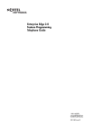
General description :
Where a series of many A/C units ( close controls ) are installed for cooling a single environment - tipically in Telecom switching rooms - one unit
is configured as STAND-BY. This unit intervenes when a RUNNING unit is stopped because of an alarm or for giving a rest to the running unit
in
order to balance the working hours for each close control.
In the picture above the second running unit becomes a stand-by one and the third stand-by units intervene becoming a runnning unit.
This pLAN system can be also connected with EasyTel, Carel supervisory/telemaintenance Network.
Cod. +030221401 - rel. 1.1 date 09/07/1998
4
Standard pCO for Air-Conditioning units in pLAN
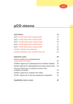
2.
INPUT/OUTPUT DESCRIPTION
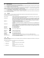
The control card represents the heart of the system, as it contains the microprocessor that executes the control algorithm.
10 W
1. Power supply connector 24 V~ 50/60 Hz 15 VA or 24 V
2. pLAN connector
3. Telephone-type connector for connection to the User terminal
unit (MMI, Man Machine Interface) or to local network
4. Yellow LED indicating the mains power present.
5. `250 VAC, 2 A slow-blow fuse (2TA).
6. EPROM containing the application program.
7. Address /real time clock card (optional).
8. RS422 or RS485 card for connection to serial line for CAREL
supervisor and/or telemaintenance network.
9. Jumpers to select the local network communication mode:
J8 at position 1-2 allows you to connect the board to a terminal
unit or, possibly, to the supervisory PC; at position 2-3 allows
you to connect the board to the local network;
J9 at position 1-2 allows the supervisory PC to reset the pCO;
at position 2-3 prevents the supervisory PC from resetting the
pCO
10. Jumpers for selecting the analogue inputs: J14=B5; J15=B6;
J28=B7; J29=B8.
11. Additional analogue inputs no.7 and no.8 (only in the cards with
8 analogue inputs) can be selected to accept either 4÷20mA or
0÷1VDC signals.
12. Analogue inputs
B(n):
Analogue input 1÷6 (8 for boards with 8 analogue
inputs, code PCOB000**1)
AVSS: Common reference for analogue inputs B(n)
From B1 to B4 preset to accept Carel NTC probes. B5 and B6
can be selected to accept either 0÷1 VDC or 4÷20 mA signals
(see point 10).
13. Digital inputs, 24 VAC (10 mA):
ID(n):
Digital inputs 1÷10;
IDCM1:
Common reference for digital inputs 1÷5;
IDCM2:
Common reference for digital inputs 6÷10.
14. Digital outputs (commutable power 2500 VA, 10 A/250 VAC):
NO(n):
Normally open contact output(n)
NC(n):
Normally closed contact output(n)
C(n):
Common contact output(n)
15. Digital inputs available at 230 VAC or 24VAC (10 mA):
ID11-230 VAC, ID12-230 VAC: Digital inputs 11 and 12 for signals at 230 VAC;
ID11-24 VAC, ID12-24 VAC:
Digital inputs 11 and 12 for signals at 24 VAC;
ID11R, ID12R:
common reference for, respectively, digital inputs ID11 and ID12.
230 VAC signals must not be connected to 24 VAC terminals, as this will damage the board itself.
16. Analogue outputs, 0÷10 VDC:
Y(n):
Analogue outputs 1 and 2, 10 mA max;
VG1:
External power for analogue outputs (24 VAC or 24 VDC);
VG0:
Reference for power and for the analogue output signal Y0 and Y1.
The "Reference" column indicates the contacts on the pCO card.
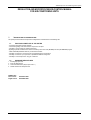
2.1.
DIGITAL INPUTS
REFERENCE
ID1 - IDCM1
ID2 - IDCM1
ID3 - IDCM1
ID4 - IDCM1
ID5 - IDCM1
ID6 - IDCM2
ID7 - IDCM2
ID8 - IDCM2
ID9 - IDCM2
ID10 - IDCM2
ID11 - ID11R
ID12 - ID12R
DIGITAL INPUT
COMPRESSOR 1 GENERAL ALARM (HIGH PRESSURE OR THERMAL)
COMPRESSOR 2 GENERAL ALARM (HIGH PRESSURE OR THERMAL)
COMPRESSOR 1 LOW PRESSURE
COMPRESSOR 2 LOW PRESSURE
DIRTY FILTER SIGNALLING
FAN THERMAL
AIR FLOW CONTROLLER
REMOTE ON / OFF
THERMAL RESISTANCE 1
THERMAL RESISTANCE 2
HUMIDIFIER LEVEL CONTACT
PRESENCE OF FIRE
Cod. +030221401 - rel. 1.1 date 09/07/1998
5
Standard pCO for Air-Conditioning units in pLAN
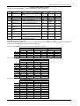
2.2.
ANALOG INPUTS
REFERENCE
B1 - AVSS
B2 - AVSS
B3 - AVSS
B4 - AVSS
B5 - AVSS
B7 - AVSS
B8 - AVSS
2.3.
DIGITAL OUTPUTS
REFERENCE
C1-NO1
C2-NO2
C3-NO3
C4-NO4
C5-NO5
C6-NO6
C-7-NO7
C-8-NO8
C-9-NO9 or C9-NA9
C10-NO10 or C10-NA10
C11-NO11 or C11-NA11
2.4.
ANALOG INPUT
AMBIENT TEMPERATURE PROBE
AIR THROW TEMPERATURE PROBE
OUTLET WATER TEMPERATURE PROBE
EXTERNAL AIR / INLET WATER TEMPERATURE PROBE
AMBIENT HUMIDITY PROBE
CURRENT MEASUREMENT PROBE IN THE HUMIDIFIER
HUMIDIFIER INLET-WATER CONDUCTIVITY PROBE
DIGITAL OUTPUT
DEHUMIDIFICATION
MAIN FAN - (ACTIVE UNIT)
ENERGY SAVING VALVE
HUMIDIFICATION / HUMIDIFIER POWER REMOTE-CONTROL SWITCH
COMPRESSOR 1 CAPACITY CONTROL / HUMIDIF. WATER-LOAD
COMPRESSOR 2 CAPACITY CONTROL / HUMID. WATER-DRAIN
3 POINT COLD VALVE OPENING / COMPRESSOR 1
3 POINT COLD VALVE CLOSING / COMPRESSOR
3 POINT WARM VALVE OPENING / RESISTANCE 1
3 POINT WARM VALVE CLOSING / RESISTANCE 2
GENERIC ALARM SITUATION
ANALOG OUTPUTS
REFERENCE
VG0 - Y0
VG0 - Y1
ANALOG OUTPUT
COLD WATER RAMP
WARM WATER RAMP
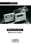
Connections :
In the following picture the wiring between pCO and devices is shown :
Cod. +030221401 - rel. 1.1 date 09/07/1998
6
Standard pCO for Air-Conditioning units in pLAN
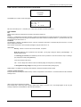
3.
INITIAL INSTALLATION OR UPDATING THE EPROM
The initial installation can be divided into three parts:
a) Hardware connection
AFTER MAKING SURE THAT THE MATERIAL RECEIVED CORRESPONDS EXACTLY TO THAT ORDERED, BEGIN UNPACKING AND
CONNECT THE INDIVIDUAL PARTS TO ASSEMBLE THE CONTROLLER.
The sequence of the operations is as follows:
• connect the telephone cable between the user terminal and the relay board.
Insert the program eprom into the special socket .
* BE CAREFUL TO INSERT THE EPROM IN THE CORRECT DIRECTION
connect the probes and devices to the relay card, as per the input/output table on page 4
connect the power supply to the interface
connect the card in pLAN using the J11 connector
b)pLAN configuration (see chapter 8.0 pLAN network))
c) Software initialisation
SOFTWARE INITIALISATION INVOLVES SETTING THE FOLLOWING:
• the control parameters (set-points, alarm thresholds, etc.)
• the type of control (proportional; proportional +integral; compressor rotation, etc.)
• the available devices (compressors; valves; etc.)
• ALL THE SELECTED DATA IS STORED IN THE PERMANENT MEMORY SO AS TO AVOID IT BEING LOST WHEN THE UNIT IS
CLEARED.
d) Updating the EPROM program
Every time the eprom is changed, the unit must be reprogrammed. To carry out this operation select the parameter found in the “M_DEFAULT”
window in “UNIT INSTALLATION “, protected by manufacturer’s password.
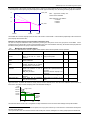
4.
REGULATION STRATEGIES
The temperature control can be of the proportional or proportional + integral type; selection is possible in the M_MANUF_PARAM2 window, "Unit
configuration under manufacturer’s word” branch. The proportional control operates according to the difference between the temperature or
humidity requested (SET POINT) and the value actually being measured, consequently real. The P+I regulation depends on the difference
between the requested temperature and the temperature being measured and on the permanence time (the integration constant is selectable at
the M_MANUF_TIME2 window). The humidity control is only proportional.
The PROPORTIONAL BAND defines the area of the temperature / humidity control. The control effect is proportional to the deviation from the
set-point. The DEAD ZONE defines an area near the set-point in which no device is energised.
PROPORTIONAL CONTROL
HEATING
COOLING
DEAD ZONE
HALF OF TOTAL
SET-POINT
SET BAND
HALF OF TOTAL
STEP CONCEPT
By step is meant an area of the proportional band which defines the values of switching on and off of a device (e.g. compressors; resistance;
humidifier; etc.)
MEANING OF STEP
HOT STEP
•
COLD STEP
the hysteresis is expressed as half the range between switching on (ON) and switching off (OFF).
Cod. +030221401 - rel. 1.1 date 09/07/1998
7
Standard pCO for Air-Conditioning units in pLAN
5.
5.1.
TEMPERATURE REGULATION DIAGRAMS
TWO-COMPRESSOR UNIT WITHOUT THE ENERGY-SAVING OPTION
Factory values:
- Compressor1set: 25%
Compressor1 hysteresis: 25%
- Compressor2set: 75%
Compressor1 hysteresis: 25%
If factory capacity-controlled compressors are utilised the steps of the compressors and its capacity controls coincide.
5.2.
A TWO-COMPRESSOR UNIT WITH THE ENERGY SAVING OPTION
Factory values:
- Compressor1set: 49%
- Compressor2set: 82%
Compressor1 hysteresis: 16%
Compressor1hysteresis: 16%
If factory capacity-controlled compressors are utilised the steps of the compressors and its capacity controls coincide.
Cod. +030221401 - rel. 1.1 date 09/07/1998
8
Standard pCO for Air-Conditioning units in pLAN
5.3.
SINGLE-COMPRESSOR UNIT WITHOUT ENERGY SAVING OPTION
Factory values:
- Compressor set: 50%
Compressor hysteresis: 50%
If factory capacity-controlled compressors are utilised the step of the compressor and its capacity control coincide.
5.4.
SINGLE-COMPRESSOR UNIT WITH THE ENERGY SAVING OPTION
Factory values:
- Compressor1 set: 66% Compressor1 hysteresis: 33%
If factory capacity-controlled compressors are utilised the step of the compressor and its capacity control coincide.
Cod. +030221401 - rel. 1.1 date 09/07/1998
9
Standard pCO for Air-Conditioning units in pLAN
5.5.
TWO-RESISTANCE UNIT
Rampa Acqua Calda
Factory values:
- Resistance1 set: 25%
- Resistance2 set: 75%
5.6.
HOT
RAMP
WATER
Resistance1 hysteresis: 25%
Resistance 2 hysteresis: 25%
SINGLE-RESISTANCE UNIT
Rampa Acqua Calda
Factory value:
- Resistance set: 50%
Resistance hysteresis: 50%
Cod. +030221401 - rel. 1.1 date 09/07/1998
10
HOT
RAMP
WATER
Standard pCO for Air-Conditioning units in pLAN
6.
6.1.
DEVICE MANAGEMENT:
COMPRESSORS
Once started a compressor can not be stopped before 1 min. (factory-made) (MASK-SELECTABLE VALUE).
Once started a compressor can not be stopped before 6 min. (factory-made ) (MASK-SELECTABLE VALUE).
The possible starting of the second compressor can not take place within 3 min. from the starting of the first one (factory-made)
(MASK-SELECTABLE VALUE).
In the two-compressor configuration the compressor ROTATION can be selected
RESISTANCE
In the 2-resistance configuration the following 2 functions are available:
• STANDARD
during connection:
RESISTANCE1
RESISTANCE1 + RESISTANCE2
during disconnection:
RESISTANCE1 + RESISTANCE2
RESISTANCE1
• BINARY
during insertion
RESISTANCE1
RESISTANCE2
RESISTANCE2 + RESISTANCE1
during connection
RESISTANCE2 + RESISTANCE1
RESISTANCE2
RESISTANCE1
6.2.
DEHUMIDIFICATION STOP
The HIGH-LIMIT step operates during the dehumidification as follows:
- when reaching the upper limit of the cold band (85%) the HIGH-LIMIT step is energised and stops the dehumidification.
the step remains energised up to a value of 15% of the warming band, and the dehumidification will start again only if still
requested.
6.3.
NOTES ON THE ENERGY SAVING
In order to be able to exploit the Energy Saving option the following relationship has to be verified:
Tambient - Twater > (SETenergy saving + IST energy saving)
The value SET ENERGY SAVING is mask-selectable (M_MANUF_PARAM10 window in the "General parameters" branch).
If this situation is verified then the following will occur:
- if in the M_MANUF_PARAM1window ("Compressors with valve in Energy Saving") you answer yes, then the compressor steps within the band
are delayed in reference to the cold-water ramp, but only when the necessary conditions for the energy saving operation occur. In the opposite
case, namely energy saving being enabled but in the absence of the functioning conditions, the compressors operate normally.
- if you answer no in this window, then the compressor steps are eliminated and only the ramp in action is maintained in the presence of the
conditions which require that energy saving be started. In the opposite case the compressors operate normally.
6.4.
MANUAL CONTROL
This part of the program allows you to manually operate the unit’s DEVICES, thus excluding the operation of the pCO control, but maintaining the
interlock with the protections in order to ensure the security and integrity of the components being utilised.
To enable manual functioning it is necessary to carry out the operations described in the paragraph dedicated to the pCO keypad.
The manual state of the machine is identified by the appearance of the message “Manual procedure” on the last line of the display.
Cod. +030221401 - rel. 1.1 date 09/07/1998
11
Standard pCO for Air-Conditioning units in pLAN
7.
HUMIDITY REGULATION GRAPH
Humidity regulation can be selected from the M_MANUF_CONF4 window in
UNIT CONFIGURAT., protected by the manufacturer’s password.
DEHUMIDIFICATION can be carried out:
- by means of the compressor starting (selected in the mask
M_MANUF_PARAM2 within the "PARAMETRI GENERAL" branch);
- with capacity control of the cold-water ramp
- through the reduction of the fan speed
- Dehumidification is enabled only if the ambient temperature falls within the
alarm limits.
FOR
VALUES
EXCEEDING
THIS
TEMPERATURE
RANGE
DEHUMIDIFICATION IS INHIBITED (see graphs of the temperature control).
Humidification can be carried out through the ON/OFF control as for the
dehumidification, described above (that is a humidification step is selected in
exactly the same way as for dehumidification) or with the integrated-humidifier
control
(selectable from M_MANUF_CONF4 mask, under the “Unit
configuration” branch, protected by manufacturer’s password).
7.1.
HUMIDITY CONTROL
HUMIDIFICATION
DEHUMIDIFICATION
SET BAND
HALF OF TOTAL
Integrated humidifier control
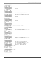
The humidifier control standard pCO for air conditioning units manages the immersed-electrode humidifiers (to be paired with the OEM kits) , can
control all the humidifiers from 1 to 42Kg/h , three-phase single-phase, with power-supply voltage from 200 to 660 V.( 220-240 V or 380-415 V
voltages are recommended). For the regulation an eight analog-input pCO interface is being utilised along with an optional card, so as the pCO
interface can read the signal from the TAM current transducer, the conductivity-reading signal and the full sensor. The pCO, in accordance with
the current and relative humidity, controls the steam production and the working conditions of the humidifier; it also manages and signals all the
states and alarms of the humidifier.
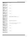
pCOUMID0000 card connection diagram:
G
220 Vac
24Vac
G0
RS422
CONDUCTIVITY
B8
J1
+24
1
B7
CURRENT
B6
J15
AVSS
J14
B5
clock
VG0
VG1
Y2
B4
AVSS
1
J2
B8 G0
B7
G
G0
O1 O2
B3
B2
J20
J6
J5
J4
AVSS
Y1
B1
1
ID11R
LEVEL
1
IDCM2
ID10
ID11
J3
J21
ID7
ID6
1
ID12
NO11
1
R11
IDCM1
ID5
C11
ID4
NC11
J4
R10
NO10
C10
J22
1
ID1
C1
R9
NO1
R2
J5
NO9
NC9
R8
R3
1
T1
C3
NO3
R7
R4
R6
R5
NO7
TAM
NO4
J24
J6
C5
NO6
C6
NO5
R13
R12
NO13
C12
1
C13
NO12
L1
N
Cod. +030221401 - rel. 1.1 date 09/07/1998
POWER
C4
C7
J2
J1
NO2
1
C8
DRAIN
J3
C2
C9
NO8
ID3
ID2
R1
NC10
24 Vac
ID9
ID8
ID12R
12
FILL
T2
C1
C2
L1
L2
Standard pCO for Air-Conditioning units in pLAN
Description of the humidifier parameters
To select and control the humidifier it is necessary to properly preset the following parameters:
N.
1
NAME
Nominal cap.
U.M.
kg/h
RANGE.
0.42
DEF.
3
Voltage
Phase no.
TAM model
Preset capacity
DESCRIPTION
Cylinder nominal or maximum-output
capacity
Supply voltage
Phase no. of the mains
TAM model utilised
Capacity preset as maximum
2
3
4
5
Volt
....
.....
kg/h
220
1
100
3
6
Humidity set-point
Set-point of the humidity regulation
rH%
7
Humidity
Band of the humidity regulation
rH%
differential
High
humidity High humidity alarm threshold
rH%
threshold
Low
humidity Low humidity alarm threshold
rH%
threshold
C0
Algorithm constant (see the following ...
paragraph)
C1
Algorithm constant
...
(see the following paragraph)
0.660
1/3
50.700
30%Pn..
100%Pn
0.100
rH%
0.100
rH%
0.100
rH%
0.100
rH%
...
...
70
8
9
10
11
50
10
80
30
93
Preset tables of the C0-C1 parameters
The C0 and C1 constants change according to the type of humidifier being connected. In the following tables the values of C0 and C1are reported
as a function of the nominal capacity (columns) and of the voltage (rows) :
C0 and C1 for F200MA single-phase cylinders with a nominal capacity from 1 to 3Kg/h :
Nominale Capacity in Kg/h
1 Kg/h
2 Kg/h
C0
C1
C0
C1
208
90
70
96
70
220
78
70
86
70
230
72
70
80
70
240
67
70
74
70
C0 and C1 for F400TA three-phase cylinders with a nominal capacity from 3 to 5 Kg/h :
Nominal Production in Kg/h
3Kg/h
5Kg/h
C0
C1
C0
C1
208
94
150
100
150
220
84
150
90
150
230
78
150
83
150
240
72
150
77
150
380
34
150
39
150
400
31
150
37
150
415
29
150
35
150
440
27
150
33
150
480
25
150
31
150
575
20
150
26
150
C0 and C1 for E400TA three-phase cylinders with a nominal capacity from 8 to 13 Kg/h:
Nominal Capacity in Kg/h
8 Kg/h
13 Kg/h
C0
C1
C0
C1
208
95
250
103
250
220
84
250
93
250
230
78
250
85
250
240
72
250
79
250
380
34
250
37
250
400
32
250
34
250
415
30
250
32
250
440
28
250
30
250
480
26
250
27
250
575
21
250
22
250
Cod. +030221401 - rel. 1.1 date 09/07/1998
13
3 Kg/h
C0
103
93
87
82
C1
70
70
70
70
Standard pCO for Air-Conditioning units in pLAN
C0 and C1 for I400TW three-phase cylinders with a nominal capacity from 23 to 42Kg/h
Nominal Capacity in Kg/h
23Kg/h
33Kg/h
C0
C1
C0
C1
208
57
500
59
500
220
52
500
53
500
230
48
500
49
500
240
44
500
46
500
380
20
500
22
500
400
18
500
20
500
415
17
500
19
500
440
16
500
17
500
480
14
500
16
500
575
11
500
13
500
380
400
415
440
480
575
7.2.
Nominal Capacity
42Kg/h
C0
C1
23
150
21
150
20
150
19
150
18
150
15
150
Programming of the humidifier
Selection of the type of humidifier
To select the type of humidifier to be controlled you must properly preselect 4 parameters in the masks intended for the humidifier under the
manufacturer’s password:
NOMINAL C. is the nominal steam capacity or maximum cylinder delivery that is available. It is possible to preset values ranging from 1Kg/h to
42 Kg/h.
VOLTAGE is the voltage value of the power supply. It is possible to preselect values ranging from 0 to 660 V.
PHASE NUMBER is the phase number of the power supply. It is possible to preset 1 or 3 phases (single-phase or three-phase)
TAM MODEL you select the model of amperometric transformer to be utilised. By presetting 0= TAM 50, 1=TAM 100, 2=TAM 150, 3=TAM 300,
4=TAM 500 , 5=TAM 700
DRAIN ENABLING WITHOUT VOLTAGE you preset how to carry out the drainage, that is to say with the power remote control switch being
connected or disconnected.
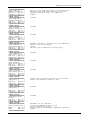
Capacity and humidity regulation
The regulation of the humidifier steam capacity depends on:
-Humidity Regulation
-Preset capacity CAPACITY (window M_PARAM_USER4 protected by manufacturer’s password)
The humidity regulation is carried out by the control based on the reading of the humidity probe at a set-point and a humidity differential. The
control calculate a proportional humidity error ERP :
100%
ERP
0%
DIFFERENZ.
UMIDITÁ %rH
SET-POINT
Cod. +030221401 - rel. 1.1 date 09/07/1998
14
Standard pCO for Air-Conditioning units in pLAN
The preset capacity is the maximum required capacity and is a value that can change between the 30% of nominal C. and the 100% of nominal
C. According to the nominal capacity, the preset capacity and the ERP proportional humidity error, the following humidifier graph will be obtained :
A
100%P_NOM
B
C
30%P_NOM
100%ERP
10%ERP
ERP = propotional humidity error
relevant set and differential
Steam production to de obtained :
A-100%Pn
B-50%Pn
C-30%Pn
0%ERP
The humidifier has a minimum capacity equal to the 30% of the nominal C. when the ERP = 0 and increases proportionally to the increase of the
preset capacity when the ERP=100%
Monitoring of the steam capacity and of the humidifier characteristic values
The user can verify the instantaneous steam production by checking the value present in the mask group bound to the MENU button.
Furthermore, the user will be able to monitor some characteristic values such as the feedwater conductivity, the absorbed current per phase and
the different working modes in the group of masks bound to the I/O button.
7.3.
Management of the humidifier Alarms
Below the various detectable alarms are listed, together with the detection criterion and the possible corrective operations.
DISPLAY
CRITERIA
OPERATION
RELA SIRENS
Y
Alarm deficiency of When the water level reaches the Turn off the power
Yes
Yes
current
sensor of full and Im <5%In is Empty out the cylinder2
measured 1
Alarm deficiency of Load valve open for more than 20 None
Yes
Yes
water
minutes consecutive
High or low humidity Humidity over or below the preset None
Yes
Yes
alarm
threshold. Signalled only 20 minutes
after the pressure of the ON button
Foam
presence Foam has been detected inside the The situation is managed up to its NO
NO
indication
cylinder. The presence of foam is extinction with a special procedure by
signalled in the “i/o”
the control.
HUMI_PCO_IO window.
(temporarily maximum capacity is not
guaranteed)
Full cylinder indication
The
cylinders
saturated
with (cylinder replacement is suggested)
NO
NO
limestone.
High current alarm
Current higher than the established Forced drain for 5 seconds. Cut off
limits (see relevant chapter)
power.
High current alarm. To prevent the current from raising over the maximum allowable values, limits have been established. These however are
bound to time, since they must allow temporary peaks at the instrument switching on.
Imax
300%In
High current
250%In
200%In
170%In
130%In
Forced
drain
0
20
60
t
The forced drain lasts 5 seconds, and is not signalled. The high current alarm causes a 30-second water drainage and stops the humidifier.
In case of current failure neither the control should operate, but if only a phase is absent you could measure no current whereas actually this is
above the security threshold
2 This to prevent the current, once the alarm has been reset and the power contactor reenergised, from raising quickly beyond the allowed limits.
1
Cod. +030221401 - rel. 1.1 date 09/07/1998
15
Standard pCO for Air-Conditioning units in pLAN
8.
PLAN NETWORK
Every pLAN node must be addressed to be identified by the other nodes. Each address (an integer number) must be unique in the network for
avoiding messages mismatch: in case two or more nodes have the same identifing address the network cannot work.
The max address number selectable is in the 1-16 range for the Terminals and 1-16 for the pCO main boards.
I
BECAUSE OF HARDWARE CHARACTERISTICS IT IS POSSIBLE TO CONNECT UP TO 16 ADDRESSES.
A example of combinations could be :
8.1.
8 Terminals + 8 pCO main boards
pCO MAIN BOARD ADDRESS SELECTION
pCO main boards are addressed using the additional PCOADR0000/PCOCLKMEM0 plug-in cards. They have these part numbers:
F
F
PCOCLKMEM0
Plug - in board for address selection plus real time clock and calendar (only for pCO n.1)
PCOADR0000
Plug - in board for address selection (for the other pCO boards)
These boards must be present on every pCO main board for a correct networking. If the addressing board is not plugged, the pCO main board
works as stand-alone without interacting with all the others local network nodes (pCO main boards and Terminals).
Adr
0
1
2
3
4
....
15
16
Sw1 Sw2 Sw3 Sw4
not possible
on
off
off
off
off
on
off
off
on
on
off
off
off
off
on
off
....
....
....
....
off
on
on
on
on
on
on
on
Sw1
Sw2
Sw3
Sw4
State off on off on off on off on
P
0 1 0 2 0 4 0 8
Addr=P(Sw1)+P(Sw2)+P(Sw3)+P(Sw4)
Sw1
OFF
STATUS LED
ON
R Y G
Sw2
present only in pCOADDCLK0
Sw3
Sw4
Sw5
NOT USED
OFF
ON
PCOADR0000 or PCOADDCLK0
Address selection
(see table)
to be inserted on pCO main board - clock board pin-strip
In the application standard air conditioning + humidifier EPSTD*CZUB unit, the dip-switches configuration allowed for the pCO cards are the
following :
1
2
3
4
Unit n.1
Unit n.2
5
Unit n.5
Unit n.3
6
Unit n.6
Cod. +030221401 - rel. 1.1 date 09/07/1998
Unit n.4
7
8
Unit n.7
Unit n.8
16
Standard pCO for Air-Conditioning units in pLAN
If all the dip-switches are OFF (not allowed configuration) the R-Y-G Leds are lit.
PCOADRxxxx boards have three LEDs on the top side for indicating basic node status. They are Red, Yellow and Green coloured.
LED
STATUS
ON
DESCRIPTION
pCO main board is syncronized with all the other pLAN nodes. The node is working correctly.
OFF
pCO main board is not network conneceted or it doesn' t receive any signal from the pLAN
BLINKING
pCO main board is transmitting data to other network nodes
OFF
pCO main board is not transmitting messages
OFF
ON
No hardware and software problem
pCO main board software not compatible or variables database not correct
Contact Carel Service
GREEN
YELLOW
RED
BLINKING pCO main board hardware is not compatible - RAM is smaller than 32KB. The pCO board model
is just for working in a stand-alone mode.
At the start-up all Leds are ON and after few seconds OFF again. After 5-15 secs elapse , the led configuration is among those listed above.
NOTE: If PCOADRxxxx board is removed ( or it fails ) while pCO main board is working it doesn’t affect the correct program running, but the
next restart, for instance after a black out or after having replaced a board, the pCO main board doesn't recognize any address card
and it is excluded from the network system.
I For a correct pLAN working every PCOADRxxxx card must be left inserted on its own pCO main board during the run-time.
8.2.
pCO TERMINALS ADDRESS SELECTION
Terminal address is programmed by means the dip-switches set on the Terminal board rear side. Dip-switches are selectable without removing
the Terminal plastic case. Ref. to the pCO main board addressing table for setting Terminal address and refer also to the picture below.
Microprocessor
ON
Dip-switch
pLAN telephone connector
SW
1 2 3 4 5
OFF
ALWAYS OFF
In the application standard air conditioning + humidifier EPSTD*CZUB unit, the dip-switches configuration allowed for the pCO Terminal are the following :
Sw1
Sw2
Sw3
Sw4
Sw5
State off on off on off on off on off on
P
0 1 0 2 0 4 0 8 0 16
Addr=P(Sw1)+P(Sw2)+P(Sw3)+P(Sw4)+P(Sw5)
In the application standard air conditioning + humidifier EPSTD*CZUB unit, the dip-switches configuration allowed for the terminals are the following :
9
10
11
12
Terminal n.1
13
Terminal n.2
14
Terminal n.3
15
Terminal n.4
16
Terminal n.5
Terminal n.6
Terminal n.7
Terminal n.8
I
I
SW6,SW7,SW8 ALWAYS OFF.
NOTE:
Take care in avoiding to leave all the dip switches on OFF position. In this case the network will not work properly.
Cod. +030221401 - rel. 1.1 date 09/07/1998
17
Standard pCO for Air-Conditioning units in pLAN
8.3.
NETWORK NODES ADDRESSING PROCEDURE
After having electrically connected every node by T-DEVICES as described before, follow these stages for completing the nodes addressing
depending on the project strategy chosen.
F
pCO main boards and Terminals ( if they have an external power supply) powered OFF.
F
Select the pCO main board address by means of the dip switches located on PCOADRxxxxx boards looking at the above table and
instructions.
F
Insert the PCOADRxxxxx card into the pin strip usually reserved for the clock board on pCO main board. Make this operation carefully for
not damaging the connectors and the boards. Touch with hands a metal case connected to earth before handling every board (see also
pCO User Manual).
F
Repeat this procedure with all the other pCO main boards you are going to install into the network.
F
Address Terminals using the dedicated dip switches on the Terminal rear side.
F
pCO main boards and Terminals ( if they have an external power supply) powered ON. At this point all the addresses are recognized by all
the pCO main boards and Terminals.
F
Now pLAN can be ready to be logically configured (see after).
NOTE:
The network nodes addressing procedure must be done and checked every time a new pCO main board or a new Terminal is linked to
the network and when a new Eprom program is installed on a pCO main board.
If the user realize to have programmed wrong addresses, the addressing procedure must be repeated from scratch.
8.4.
pLAN NODES LOGIC CONFIGURATION
This chapter describes how to create logic relations among all the Terminals and pCO main boards connected - and already addressed - in
pLAN.
Before starting this procedure check that every node address is properly programmed.
This procedure can be carried out using just one Terminal, but with all the other Terminals connected to pLAN.
8.5.
USER-TERMINALS LOGIC TYPES
Before describing the config. procedure , a description about the two modes how a Terminal can be configured is explained.
A pCO user-terminal in the pLAN will be considered as PRIVATE or SHARED (hardware is the same) in the pLAN strategy.
F
PRIVATE pCO user-terminal
The terminal is dedicated to work with only one pCO main board.
This terminal will receive and transmit data only to one (its own) pCO main board. It means that all messages which appear on the
display and leds will be driven by one pCO main board. Every key-stroke signal will be sent to one pCO main board.
A terminal is defined as PRIVATE by the user during an initial configuration procedure ( a built-in function in BIOS firmware ). Terminal
status ( Private or Shared ) cannot be changed during the run time for avoiding any system bad working.
PRIVATE terminals can also drive ( option ) a local serial printer.
F
SHARED pCO user-terminal
A SHARED terminal can be associated to two or more pCO main boards.
In a certain moment only one pCO main board can keep the shared terminal under control and sending or receiving commands to/from a
pCO terminal.
Switching a shared terminal from one to another pCO main board can be done in two ways:
F
Automatically: Depending on the particular application program. The EasyTools application program, built-in the pCO main
board Eprom, can set a dedicated variable for this aim.
F
Manually: Pushing dedicated keys on pCO terminal keyboard. A terminal is defined as SHARED by the user during an initial
configuration procedure ( a built-in function in BIOS firmware ) when it is possible to assign also the pCO main board associated
address.
I
Max no. 3 terminals can be software-driven by only one pCO main board. Among these three terminals only one can be
assigned as SHARED. The remaining two terminals must be configured as PRIVATE.
I
A SHARED and a PRIVATE Terminal must be of the same type.
Cod. +030221401 - rel. 1.1 date 09/07/1998
18
Standard pCO for Air-Conditioning units in pLAN
Every pCO main board up to date PRIVATE terminals indications continuously. A SHARED terminal is up to date by the pCO main board which
is keeping the terminal under control in that particular moment.
Ex:
PRIVATE
PRIVATE
S
S
pCO
SHARED
pCO
4
1
Switching sequence
S
S
PRIVATE
PRIVATE
pCO
2
pCO
3
In the picture above the SHARED terminal is associated to pCO main boards no. 1,2,3,4 but in this moment it is kept under control by pCO main
board no. 2. <S> is just a logic switch indicating which pCO main board is controlling the shared terminal at a certain time.
For switching to the next pCO main board :
F push keys. The switching sequence is (1--> 2---> 3---> 4---> 1--->2 ....) or
F wait for the automatic switching sequence managed by the particular application program
VERY IMPORTANT. In the application standard air conditioning + humidifier EPSTD*CZUB unit, two possibilities are given to the customer. First
one is to connect a terminal for any pCO board. Second one is to connect just a terminal (number 16) shared between all pCO boards. It could be
also possible to foresee a mixed configuration : private terminals plus a shared terminal.
8.6.
pLAN CONFIGURING PROCEDURE
Follow these stages for a correct pLAN Terminals configuration. Firstly the procedure for a LCD display Terminal is described; then the one for a
LED display Terminal.
The program is stored in the Terminal microprocessor.
STAGE 1: pCO main board selection
This stage associates a pCO main board to the Terminal.
Push simoultaneously the first three keys on the upper left corner of the keyboard. Push them for at least 5 seconds.
5 sec.
6
menu
This mask appears:
Terminal Adr: nn
I/O Board Adr: 01
Terminal Adr is not changable. <nn> represents the address set on the dip-switch on the rear side of the Terminal.
I/O Board Adr field shows the pCO main board address that is connected to the Terminal.
Arrow keys: change the pCO main board address in order to connect the Terminal with another pCO main board.
If no pCO main board is connected with the Terminal a '--' is shown in place of the figure representing the pCO main
board address. Push Arrow Keys for changing it. If no pCOmain board is connected to the pLAN or no pCO main board
is addressed it is not possible to make any communication.
Enter: Exit from the STAGE 1 procedure. STAGE 2 first mask appears.
The configuration procedure is automatically cleared if no key is pushed within 15 seconds from the former key-stroke.
Cod. +030221401 - rel. 1.1 date 09/07/1998
19
Standard pCO for Air-Conditioning units in pLAN
STAGE 2: Selection of Terminals associated with a pCO main board.
Terminal Config
Press ENTER
to continue
Push ENTER key to Continue. A new mask appears:
P:01
Trm1
Trm2
Trm3
Adr Priv/Shared
09
Pr
none -16
Sh Ok? No
We can now associate up to no. 3 Terminals (Trm1 , Trm2, Trm3) to the pCO main board addressed 01.
Fields LEGENDA:
P:01
Address of pCO main board connected to the Terminal. In this case the address is 01.
Trm(x):
Terminal. (x) = 3 indicates the max number of terminals (3) which can be logically related to a single pCO main board. The Terminal you are using
for configuring the pLAN could not be among Trm1/2/3 indicated on the mask: for instance it could have address 11 ( not shown in the mask ) and
not associated to pCO main board no. 01.
Priv/Shared:
Terminal attribute : PRIVATE or SHARED (see above). If the Trm1 is Shared it means that it is associated with pCO main board n. 01 and at
least to another pCO main board .
Trm2 is Private: it means that it can be associated (managed) by only pCO main board no. 01.
PROCEDURE:
Enter key: it allows to move the cursor to the mask fields , in sequence.
Arrow keys: When the cursor is positioned on the field where you are going to change an address, push arrow keys
selecting another address.
for
For confirming your selection press ENTER key until the cursor is positioned on Ok? field. Push Arrow keys for selecting Y
(Yes) or N(No) and confirm pushing ENTER key.
If Yes: data are stored in the memory
If No: You can change some value that couldn' t be selected properly according with your pLAN strategy.
For exiting without storing changes into memory just wait for 30 seconds without pushing any key.
Repeat STAGE 1 and STAGE 2 for associating other Terminals to other pCO main boards present in pLAN.
TERMINAL RUNNING MESSAGES
If the pCO main board controlling the Terminal is faulty or there is some problem in communication or it was disconnected from the Terminal this
message occours:
I/O Board xx faulty
where xx stands for the pCOmain board address.
If the Terminal doesn' t receive any token message ( network syncro signal ) for at least 10 sec., this message appears on the LCD (This
message corresponds to the PCOADDxxxx Green LED OFF information.) :
NO LINK
Cod. +030221401 - rel. 1.1 date 09/07/1998
20
Standard pCO for Air-Conditioning units in pLAN
9.
STAND-BY
The connection of pCO boards in a pLAN local network allows them to communicate with one another and exchange variables.
The main function of this exchange of variables is to allow all the units to be controlled by one single pCO terminal.
In addition, it allows the units to be rotated according to a time schedule, with the possibility to leave one of them in Stand-By, ready in the case
where one of the units in operation malfunctions. Below is a schematised diagram of the connections which need to be made.
The connection between boards in the pLAN network is made
using an AWG20/22 shielded cable, twisted pair + shield. The
boards are connected in parallel, using terminal J11 as reference.
WARNING: make sure the order of connection is respected.
The following parameters manage the rotation of the units and are present only in the screen of unit number 1. They are listed and described below.
• screen M_MANUF_PARAM25 (manuf. branch). Number Units: indicates the total number of units involved in the scheduled rotation (the
number set must also take
into account unit number 1).
• screen M_MANUF_PARAM25 (manuf. branch). Reset Rotation: if enabled, this parameter resets the rotation; this should
be set after
having completed the parameter
installation procedures.
• screen M_MANUF_PARAM26 (manuf. branch). Select. Hours/Minutes: determines if the rotations are performed in minutes (test only) or in
hours (normal conditions)
• screen M_MANUF_PARAM26 (manuf. branch). Type of Rotation: if Cyclical the units in Stand-By follow the order 1, 2,
3...1, etc...; if
Op. Time, at the end of the rotation
time the unit with the highest number of operating
hours
is
placed Stand-By (referred to the number of
operating hours of the main fan)
• screen M_MANUF_PARAM27 (manuf. branch). Test Rotation Cycle: sets the number of minutes for the rotation test
• screen M_MANUF_PARAM27 (manuf. branch). Rotation Cycle: sets the number of hours of rotation in normal operation
One further parameter is however present on all units
• screen M_MANUF_CONF7 (manuf. branch). Unit Configuration: sets if the unit functions alone
(INDEPENDENT UNIT), that is
without being part of the rotation, or in rotation
(UNIT IN ROTATION)
Cod. +030221401 - rel. 1.1 date 09/07/1998
21
Standard pCO for Air-Conditioning units in pLAN
After all these parameters have been correctly set, the rotation reset should be performed using the Reset Rotation parameter, and then the units
should be started.
IMPORTANT. It is good practice for the units which are part of the rotation to have sequential addresses. If, for example, an installation to be
configured with 4 units in rotation and 2 independent units, the first 4 units must have addresses from 1 to 4, and the other 2 must have
addresses 5 and 6.
When a critical alarm occurs in one of the units, this unit may continue to function and the stand-by unit is switched on. List of critical alarms :
• compressor high pressure
• compressor low pressure
• electrical element thermal cut-out
• high / low ambient temperature
• high / low water temperature at outlet
• faulty ambient temperature / water outlet / external air / supply air probe
• high current at humidifier
• no current at humidifier
• no water in humidifier
• eeprom malfunction
• interruption to the pLAN local network
When a serious alarm occurs in one of the units, this unit is switched off and the stand-by unit is switched on. List of serious alarms:
• air flowmeter
• main fan thermal cut-out
• fire / smoke
• unit black-out
The PCOCLKMEM0 clock board installed in unit number 1 allows the cyclical rotation, the timer and the address of the unit in stand-by to be
store in the clock’s buffer RAM. Following a black-out, the system recommences from the state before the black-out (same unit in stand-by, the
cyclical rotation timer does not start from 0 but rather counts the hours already passed).
10.
LIST 0F THE PROGRAMMABLE SETS
When the factory values are inserted the machine is configured with the presence of the following devices:
•
•
•
•
•
•
Outlet water temperature probe
Internal humidity
Both the compressors
Both the resistance
Warm modulating valve
Cold modulating valve
Factory values being taken as machine parameters by the pCO if you answer yes to the first window of the “Init. configuration” in the
manufacturer’s menu:
SELECTABLE QUANTITIES
LEVEL
RANGE
PRE-SET
Fan hour threshold
Compressor 1 hour threshold
Compressor 2 hour threshold
Temperature probe calibration
Delivery air temp. probe calibration
Outlet water probe calibration
External air temp. probe calibration
assistance
assistance
assistance
assistance
assistance
assistance
assistance
0 / 999 (x1000)
0 / 999 (x1000)
0 / 999 (x1000)
-99°C / 99°C
-99°C / 99°C
-99°C / 99°C
-99°C / 99°C
200h
100h
100h
0°C
0°C
0°C
0°C
Manual procedure
Fan
Energy saving
Dehumidifier
Humidifier
Compressor 1
Compressor 2
Resistance 1
Resistance 2
Cold fan
Warm fan
assistance
0 / 10.0V
0 / 10.0V
N
N
N
N
N
N
N
N
N 0V
N 0V
Cod. +030221401 - rel. 1.1 date 09/07/1998
22
Standard pCO for Air-Conditioning units in pLAN
SELECTABLE QUANTITIES
LEVEL
RANGE
PRE-SET
set-points
set-points
variable
variable
23°C
50%
Temperature minimum set-point limits
Temperature maximum set-point limits
Humidity minimum set-point limits set-point
Humidity minimum set-point limits
Temperature band
Temperature neutral zone
Humidity band
Capacity
Automatic restart after voltage drop
Remote ON/OFF enabling
Compensation enabling
Compensation set-point
Compensation band
Compensation offset
Temperature alarm
low offset
high offset
user
user
user
user
user
user
user
user
user
user
user
user
user
user
user
-99.9 / 99.9°C
-99.9 / 99.9°C
0%
100%
0 / 99.9°C
0 / 99.9°C
0 / 99.9%
variable
-99.9°C
99.9°C
0%
100%
3°C
0°C
10%
3 kg/h
N
N
N
Humidity alarm
low offset
high offset
user
Outlet water temperature threshold alarm
low offset
high offset
user
Temperature set-point
Humidity set-point
Print repetition
printer
Temperature set-point automatic variation
clock
Temperature time band (1-4)
Start time
Set-point
clock
Humidity time band (1-4)
Start time
Set-point
(MANUFACTURER’S PARAMETERS)
Clock card enabling
Printer enabling
Supervisory system enabling
Delivery air probe enabling
Outlet water probe enabling
External air probe enabling
Inlet water probe enabling
Humidity probe enabling
Integrated humidifier enabling
Energy Saving enabling
No. resistance
No. compressors
Compressor capacity control enabling
Cold modulating valve enabling
Warm modulating valve enabling
Cold 3 point valve enabling
Warm 3 point valve enabling
Configuration Unit Type
clock
Regulation time
Dehumidification logic
Cod. +030221401 - rel. 1.1 date 09/07/1998
-99.9 / 99.9
-99.9 / 99.9
-99.9 / 99.9
0 / 100°C
0 / 100°C
10°C
10°C
0 / 100%
0 / 100%
20%
30%
-99.9 / 99.9°C
-99.9 / 99.9°C
2°C
20°C
0 / 999h
24h
N
00:00 / 23:59
variable
00:00
0°C
00:00 / 23:59
variable
00:00
0%
unit configurat.
unit configurat.
unit configurat.
unit configurat.
unit configurat.
unit configurat.
unit configurat.
unit configurat.
unit configurat.
unit configurat.
unit configurat.
unit configurat.
unit configurat.
unit configurat.
unit configurat.
unit configurat.
unit configurat.
general parameters
general parameters
23
0/2
0/2
Rotation / Stand-Alone
Prop. / Prop.+Integral
N
N
N
N
S
N
N
S
N
N
2
2
N
S
S
N
N
Rotation
Prop.
Normal. Open
Standard pCO for Air-Conditioning units in pLAN
SELECTABLE QUANTITIES
LEVEL
RANGE
PRE-SET
0 / 100 %
0 / 100 %
0%
100%
0 / 100 %
0 / 100 %
0%
100%
0 / 100 %
0 / 100 %
0%
100%
0%
100%
0%
100%
0%
100%
0%
100%
0 / 100%
0 / 100%
0%
100%
0 / 100%
0 / 100%
0%
100%
0 / 100%
0 / 100%
50%
50%
0 / 100%
0 / 100%
50%
50%
0 / 100%
0 / 100%
50%
35%
0 / 100%
0 / 100%
0 / 42
0 / 660
1o3
50 / 700
50%
35%
3 kg/h
220V
1
100
general parameters
general parameters
general parameters
general parameters
general parameters
general parameters
time
time
time
time
time
time
0 / 1000
0 / 1000
1/8
0/1
Hours/ Minutes
Cyclic / Running Hours
1 / 10
1 / 168
0 / 999
0 / 999
0 / 9999
0 / 9999
0 / 9999
0 / 9999
N
93
75
0
0
Hours
Cyclic
0
0
10 sec.
20 sec.
600 sec.
180 sec.
180 sec.
600 sec.
time
time
time
0 / 9999
0 / 9999
0 / 9999
10 sec.
10 sec.
3 sec.
1/2 compressor step with/without Energy Saving
Position
Hysteresis
general parameters
1/2 capacity control step with/without Energy
Saving
Position
Hysteresis
1/2/binary resistance step
Position
Hysteresis
Cold modulating valve
Start
End
Warm modulating valve
Start
End
Cold 3 point valve
Start
End
Warm 3 point valve
Start
End
Humidification step
Position
Hysteresis
Dehumidification step
Position
Hysteresis
Low temp. limit (stop dehumidification)
Position
Hysteresis
High temp. limit (stop dehumidification)
Position
Hysteresis
Humidifier nominal capacity
Humidifier Voltage
Humidifier phase No.
Humidifier TAM model
general parameters
Drain enabling without voltage
C0 parameter
C1 parameter
Number of Units engaged for Rotation
Rotation’s Reset
Select Hours / Minutes of Rotation
Rotation’s Type
Rotation Cycle Test
Rotation Cycle Time
Fan start delay time
Fan stop delay time
Integration time
3 point valve opening time
Low pressure alarm delay
Probe alarm delay (temperature, humidity, outlet
water)
Air flow controller alarm delay
Delay between 2 capacity controller start
Delay between different resistance start
general parameters
Cod. +030221401 - rel. 1.1 date 09/07/1998
general parameters
general parameters
general parameters
general parameters
general parameters
general parameters
general parameters
general parameters
general parameters
general parameters
general parameters
general parameters
general parameters
24
Standard pCO for Air-Conditioning units in pLAN
11.
ALARM MANAGEMENT
Every state of alarm is signalled:
- acoustically by the buzzer incorporated into the pCO relay card;
- visually by the LED lighting of the ALARM button
It is possible to recall a message relative to an alarm occurred by pressing the ALARM button. To rearm the alarms merely press the ALARM
button when an alarm window is displayed.
The alarms are divided into three categories:
LED signalling
Serious alarms
yes
Device alarms
yes
Signalling alarms
yes
ALARM
compressor 1 general
general compressor 2
low pressure 1
low pressure 2
air flow controller
fan general
resistance 1thermal
resistance 2 thermal
fire / smoke
V
Window signalling
yes
yes
yes
Remote signalling
yes
yes
yes
Stops the unit
yes
no
no
C1 C2 R1 R2 V1 V2 V3P1 V3P2 REARM DELAY
yes
Cod. +030221401 - rel. 1.1 date 09/07/1998
25
HUMID NOTES
.
yes
imm.
imm.
imm.
imm.
imm.
yes
yes
man.
imm.
yes
yes
man.
man.
man.
imm.
imm.
imm.
yes
man.
man.
man.
man.
man.
man.
man.
man.
man.
man.
man.
imm.
imp.
imp.
imp.
imp.
imp.
imp.
imm.
imm.
imm.
1 MIN.
yes
yes
yes
yes
yes
yes
yes
yes
yes
yes
yes
man.
man.
1 MIN.
1 MIN.
yes
yes
man.
1 MIN.
yes
man.
man.
man.
man.
man.
imm.
imm.
20 MIN
imm.
imm.
yes
yes
air filter
high temperature
low temperature
high humidity
low humidity
outlet water high temperature
outlet water low temperature
comp1working hours
comp2 working hours
fan working hours
ambient temperature probe out of
order
outlet water probe out of order
inlet water temp. probe or external
air out of order
delivery air temperature probe out
of order
humidity probe out of order
high curr. in the humidifier
absence of water in the humidifier
current failure to the humidifier
clock card failure
ONLY
VIS
man.
man.
man.
man.
man.
yes
yes
ye yes yes yes yes yes yes yes
s
ye yes yes yes yes yes yes yes
s
yes
yes
ye yes yes yes yes yes yes yes
s
Stops the device
yes
no
no
yes
yes
yes
yes
LOAD
UNLOAD
Standard pCO for Air-Conditioning units in pLAN
12.
USER INTERFACE
The user interface of this application is divided into three fundamental parts:
-A USER part, not protected by password, which allows monitoring the quantities being regulated, selecting the set-point of principal
control, displaying the active alarms and the stored alarms.
- A USER part, protected by password, which allows selecting all the control parameters of the various functions and processes
managed by the program: set-point limits, regulation differential , regulation dead zone, compensation.....; only the parameters regarding functions
enabled under manufacturer’s password will be displayed and consequently selectable.
-An ASSISTANCE part , protected by password , intended for the assistance, for the hour counter management of the compressors
and machine , for the calibration of the connected probes and for forcing of the relay outputs.
-A MANUFACTURER part , protected by Password , enables the configuration of the system with the selection and activation of the
functions of the devices to be controlled.
12.1.
KEYPAD
The pCO is equipped with a 15-button keypad that along with the display represents the interface between the operator and the pCO system.
The keypad provides the operator with the following functions:
ON / OFF button
MENU button
INFO button
Energises and deenergizes the unit. The unit has to be switched on by this button in order to carry out any
control, verification or operation. (See Regulation ON/OFF)
The pressure of this button displays the first active alarm window and simultaneously it switches off the
buzzer. A second pressure of this button reactivates the alarm or the active alarm. The display of several
alarm masks can be obtained by pressing the UP / DOWN arrow buttons. If there are no active alarms in
storage, by pressing this button you go to the window NO ACTIVE ALARM.(See the regulation of the Alarms)
These buttons have a double functionality:
1) Scrolling of the mask branches; when the cursor is on the upper left
2) Increasing and decreasing the parameters or changing the values, when the cursor is at the beginning of the
parameter.
In the value pre-setting masks, by pressing the button the first time, the cursor goes to the first parameter of
the window. When pressing again, the selected parameter is confirmed and the cursor moves to the following
parameter. Afterwards, from the last parameter you return to the position on the upper left (cursor in the
0.0 position of the display)
Go to the MAIN_MASK window
Go to the next pCO-boards
MANUT button
Go to the M_VIS_TIMER1 window
PRINT button
I/O button
Usable in the version with printer
Go to the M_SYNOPTIC1 window
HOUR button
SET button
PROG button
MENU+PROG buttons
Go to the M_REG_CLOCK window
Go to the M_CALC_SETP window
The password is requested. If properly introduced, you move to the M_PARAM_USER3 window
The buttons must be pressed and released simultaneously. The password is requested. If properly introduced,
you move to the M_MANUF_PASS window
ALARM button
st buttons
ENTER button
12.2.
LED
At the side of each button a green LED is found which lights up when the associated button is being pressed and indicates in which group of
masks the user is situated.
Three other LEDs are placed under the rubber buttons and indicate respectively:
1.
ON / OFF button
green LED
indicates that the instrument is ON and operating.
2.
ALARM button
red LED
indicates the presence of an alarm condition.
3.
ENTER button
yellow LED
Indicates that the instrument is properly supplied.
Cod. +030221401 - rel. 1.1 date 09/07/1998
26
Standard pCO for Air-Conditioning units in pLAN
13.
TREE OF THE MASKS
START
ÉÍÍÍÍÍÍÍÍÍÍÍÍÍÍÍÍÍÍÍÍ»
º
º
º-- WAIT PLEASE --º
º-- READING INPUTS --º
º
º
ÈÍÍÍÍÍÍÍÍÍÍÍÍÍÍÍÍÍÍÍͼ
MENU BUTTON
MAIN_MASK
ÉÍÍÍÍÍÍÍÍÍÍÍÍÍÍÍÍÍÍÍÍ»
º00:00 00/00/00 Unit1º
ºRoom temp.
00.0 §Cº
ºRoom humid. 00.0% º
º
º
ÈÍÍÍÍÍÍÍÍÍÍÍÍÍÍÍÍÍÍÍͼ
WORK_MODE
ÉÍÍÍÍÍÍÍÍÍÍÍÍÍÍÍÍÍÍÍÍ»
º
Working mode
º
º
º
ºÛ Cooling Û Heating º
ºÛ Humid. Û Dehumid.º
ÈÍÍÍÍÍÍÍÍÍÍÍÍÍÍÍÍÍÍÍͼ
MAINTENANCE BUTTON
M_VIS_TIMER1
ÉÍÍÍÍÍÍÍÍÍÍÍÍÍÍÍÍÍÍÍÍ»
ºOperating hours:
º
ºMain fan
000000º
ºCompressor 1 000000º
ºCompressor 2 000000º
ÈÍÍÍÍÍÍÍÍÍÍÍÍÍÍÍÍÍÍÍͼ
M_MAINT_PASS
ÉÍÍÍÍÍÍÍÍÍÍÍÍÍÍÍÍÍÍÍÍ»
ºEnter maintenance
º
ºpassword
º
º
0000
º
ºRight password!
º
ÈÍÍÍÍÍÍÍÍÍÍÍÍÍÍÍÍÍÍÍͼ
M_SEL_TIMER1
ÉÍÍÍÍÍÍÍÍÍÍÍÍÍÍÍÍÍÍÍÍ»
ºMain fan hour meter º
º
º
ºThreshold: 000x1000 º
ºReq.reset: N 000000 º
ÈÍÍÍÍÍÍÍÍÍÍÍÍÍÍÍÍÍÍÍͼ
M_SEL_TIMER2
ÉÍÍÍÍÍÍÍÍÍÍÍÍÍÍÍÍÍÍÍÍ»
ºCompressor 1 hour
º
ºmeter
º
ºThreshold:: 000x1000º
ºReq.reset: N 000000 º
ÈÍÍÍÍÍÍÍÍÍÍÍÍÍÍÍÍÍÍÍͼ
M_SEL_TIMER3
ÉÍÍÍÍÍÍÍÍÍÍÍÍÍÍÍÍÍÍÍÍ»
ºCompressor 2 hour
º
ºmeter
º
ºThreshold:: 000x1000º
ºReq.reset: N 000000 º
ÈÍÍÍÍÍÍÍÍÍÍÍÍÍÍÍÍÍÍÍͼ
M_CALIBRATION1
ÉÍÍÍÍÍÍÍÍÍÍÍÍÍÍÍÍÍÍÍÍ»
ºProbe adjustment:
º
ºRoom temp.:
0.0§C º
ºSupply air: 0.0§C º
ºOut water: 0.0§C
º
ÈÍÍÍÍÍÍÍÍÍÍÍÍÍÍÍÍÍÍÍͼ
M_CALIBRATION2
ÉÍÍÍÍÍÍÍÍÍÍÍÍÍÍÍÍÍÍÍÍ»
ºProbe adjustment:
º
ºInlet water: 0.0 §C º
ºRoom humid.:0.0 %
º
º
º
ÈÍÍÍÍÍÍÍÍÍÍÍÍÍÍÍÍÍÍÍͼ
M_MANUAL1
ÉÍÍÍÍÍÍÍÍÍÍÍÍÍÍÍÍÍÍÍÍ»
ºManual procedure:
º
º
º
ºMain fan:
N
º
ºEnergy saving
N º
ÈÍÍÍÍÍÍÍÍÍÍÍÍÍÍÍÍÍÍÍͼ
Appears when the pCO is switched on
Remains visible for about 5 seconds
and is used as a warning to wait for the
machine to be initialised
Displays the current working modes
of temperature and humidity.
Displays the current working
mode. The blackened box
means that the specific
function at issue is now activated
Shows the operating time of the equipment’s
Pre-setting of the fan time operating time
established before the maintenance
As above
As above
Probe calibration window no.1
Probe calibration window no.2
Manual activation of the devices
Cod. +030221401 - rel. 1.1 date 09/07/1998
27
Standard pCO for Air-Conditioning units in pLAN
M_MANUAL2
ÉÍÍÍÍÍÍÍÍÍÍÍÍÍÍÍÍÍÍÍÍ»
ºManual procedure:
º
º
º
ºDehumidifier
N º
º Humidifier
N º
ÈÍÍÍÍÍÍÍÍÍÍÍÍÍÍÍÍÍÍÍͼ
M_MANUAL3
ÉÍÍÍÍÍÍÍÍÍÍÍÍÍÍÍÍÍÍÍÍ»
ºManual procedure:
º
º
º
ºOpen cool.fl.v.
N º
ºClose cool.fl.v. N º
ÈÍÍÍÍÍÍÍÍÍÍÍÍÍÍÍÍÍÍÍͼ
M_MANUAL4
ÉÍÍÍÍÍÍÍÍÍÍÍÍÍÍÍÍÍÍÍÍ»
ºManual procedure:
º
º
º
ºUnloader 1
N º
ºUnloader 2
N º
ÈÍÍÍÍÍÍÍÍÍÍÍÍÍÍÍÍÍÍÍͼ
M_MANUAL5
ÉÍÍÍÍÍÍÍÍÍÍÍÍÍÍÍÍÍÍÍÍ»
ºManual procedure:
º
º
º
ºOpen heat.fl.v.
N º
ºClose heat.fl.v. N º
ÈÍÍÍÍÍÍÍÍÍÍÍÍÍÍÍÍÍÍÍͼ
M _MANUAL6
ÉÍÍÍÍÍÍÍÍÍÍÍÍÍÍÍÍÍÍÍÍ»
ºManual procedure
º
º
º
ºCool. valve N 00.0 Vº
ºHeat. valve N 00.0 Vº
ÈÍÍÍÍÍÍÍÍÍÍÍÍÍÍÍÍÍÍÍͼ
M_DISABLE_HUMID
ÉÍÍÍÍÍÍÍÍÍÍÍÍÍÍÍÍÍÍÍÍ»
º Integr. humidifier º
ºDisable humid.
N º
ºManual drain
N º
ºManual drain
N º
º(120 sec of timeout)º
ÈÍÍÍÍÍÍÍÍÍÍÍÍÍÍÍÍÍÍÍͼ
PRINTER BUTTON
M_PRINTER
ÉÍÍÍÍÍÍÍÍÍÍÍÍÍÍÍÍÍÍÍÍ»
º Printer management º
ºCyclic print
000 hº
ºImmediate print of º
ºunit report
N º
ÈÍÍÍÍÍÍÍÍÍÍÍÍÍÍÍÍÍÍÍͼ
I/O BUTTON
M_SYNOPTIC1
ÉÍÍÍÍÍÍÍÍÍÍÍÍÍÍÍÍÍÍÍÍ»
º
Analog inputs
º
ºRoom Temp.
00.0 §Cº
ºSupply air -00.0 §Cº
ºRoom humid. -00.0 % º
ÈÍÍÍÍÍÍÍÍÍÍÍÍÍÍÍÍÍÍÍͼ
M_SYNOPTIC2
ÉÍÍÍÍÍÍÍÍÍÍÍÍÍÍÍÍÍÍÍÍ»
º
Analog Inputs
º
ºInlet water -00.0 §Cº
ºOutlet water-00.0 §Cº
º
º
ÈÍÍÍÍÍÍÍÍÍÍÍÍÍÍÍÍÍÍÍͼ
M_SYNOPTIC3
ÉÍÍÍÍÍÍÍÍÍÍÍÍÍÍÍÍÍÍÍÍ»
º
Digital inputs
º
ºC=Close O=Open
º
º01:CCCCC 06:CCCCC
º
º11:CC
º
ÈÍÍÍÍÍÍÍÍÍÍÍÍÍÍÍÍÍÍÍͼ
M_SYNOPTIC4
ÉÍÍÍÍÍÍÍÍÍÍÍÍÍÍÍÍÍÍÍÍ»
º
Analog outputs
º
º
º
ºCooling valve 00.0 Vº
ºHeating valve 00.0 Vº
ÈÍÍÍÍÍÍÍÍÍÍÍÍÍÍÍÍÍÍÍͼ
As above
As above
As above
As above
As above
Integrated humidifier disabling
Manual drainage activation(maximum 120 sec.)
Time interval for the cyclic print
Activation /forcing of a print
Displays the state of the analog inputs and outputs
It is displayed with the I/O button
As above
As above
As above
Cod. +030221401 - rel. 1.1 date 09/07/1998
28
Standard pCO for Air-Conditioning units in pLAN
M_SYNOPTIC5
ÉÍÍÍÍÍÍÍÍÍÍÍÍÍÍÍÍÍÍÍÍ»
º Digital outputs
º
ºC=Close O=Open
º
º01:OOO
04:OOO
º
º07:OOO
10:OO
º
ÈÍÍÍÍÍÍÍÍÍÍÍÍÍÍÍÍÍÍÍͼ
M_SYNOPTIC6
ÉÍÍÍÍÍÍÍÍÍÍÍÍÍÍÍÍÍÍÍÍ»
º
Humidifier
º
ºMain switch
OFF º
ºFill valve
OFF º
ºDrain valve
OFF º
ÈÍÍÍÍÍÍÍÍÍÍÍÍÍÍÍÍÍÍÍͼ
M_SYNOPTIC7
ÉÍÍÍÍÍÍÍÍÍÍÍÍÍÍÍÍÍÍÍÍ»
º
Humidifier
º
ºMeasur.Amps 000.00 Aº
ºTarget Amps 000.00 Aº
ºNomin. Amps 000.00 Aº
ÈÍÍÍÍÍÍÍÍÍÍÍÍÍÍÍÍÍÍÍͼ
M_SYNOPTIC8
ÉÍÍÍÍÍÍÍÍÍÍÍÍÍÍÍÍÍÍÍÍ»
º
Humidifier
º
º
º
ºWat.level open
º
ºConduct. 0000 uS/Cmº
ÈÍÍÍÍÍÍÍÍÍÍÍÍÍÍÍÍÍÍÍͼ
M_SYNOPTIC9
ÉÍÍÍÍÍÍÍÍÍÍÍÍÍÍÍÍÍÍÍÍ»
º
Humidifier
º
ºCyl. worn out
N º
ºMode
---------º
ºStatus h. ---------º
ÈÍÍÍÍÍÍÍÍÍÍÍÍÍÍÍÍÍÍÍͼ
M_VERSION
ÉÍÍÍÍÍÍÍÍÍÍÍÍÍÍÍÍÍÍÍÍ»
ºCONTROLLER STANDARD º
ºCLOSE CONTROL UNITS º
º Code EPSTDECZUB
º
ºVer.1.312 - 04/06/98º
ÈÍÍÍÍÍÍÍÍÍÍÍÍÍÍÍÍÍÍÍͼ
CLOCK BUTTON
M_REG_CLOCK
ÉÍÍÍÍÍÍÍÍÍÍÍÍÍÍÍÍÍÍÍÍ»
º
Clock & date
º
ºSetting
º
ºTime
00:00
º
ºDate
00/00/00 º
ÈÍÍÍÍÍÍÍÍÍÍÍÍÍÍÍÍÍÍÍͼ
M_CLOCK_PASS
ÉÍÍÍÍÍÍÍÍÍÍÍÍÍÍÍÍÍÍÍÍ»
ºEnter the clock
º
ºpassword
º
º
0000
º
ºRight password
º
ÈÍÍÍÍÍÍÍÍÍÍÍÍÍÍÍÍÍÍÍͼ
M_DAILY_TEMP
ÉÍÍÍÍÍÍÍÍÍÍÍÍÍÍÍÍÍÍÍÍ»
ºDaily time zone withº
ºautomatic temper.
º
ºset-point variation º
º
N
º
ÈÍÍÍÍÍÍÍÍÍÍÍÍÍÍÍÍÍÍÍͼ
M_DAILY1_TEMP
ÉÍÍÍÍÍÍÍÍÍÍÍÍÍÍÍÍÍÍÍÍ»
º
Temperature
º
ºDaily time zone 1
º
ºStart time 00:00
º
ºSet-point
00.0§Cº
ÈÍÍÍÍÍÍÍÍÍÍÍÍÍÍÍÍÍÍÍͼ
M_DAILY2_TEMP
ÉÍÍÍÍÍÍÍÍÍÍÍÍÍÍÍÍÍÍÍÍ»
º
Temperature
º
ºDaily time zone 2
º
ºStart time 00:00
º
ºSet-point
00.0§Cº
ÈÍÍÍÍÍÍÍÍÍÍÍÍÍÍÍÍÍÍÍͼ
M_DAILY3_TEMP
ÉÍÍÍÍÍÍÍÍÍÍÍÍÍÍÍÍÍÍÍÍ»
º
Temperature
º
ºDaily time zone 3
º
ºStart time 00:00
º
ºSet-point
00.0§Cº
ÈÍÍÍÍÍÍÍÍÍÍÍÍÍÍÍÍÍÍÍͼ
As above
As above
Current absorbed by the humidifier
Current to be maintained
Maximum current allowed by the cylinder
As above
As above
Current version of the software.
Regulation of the internal clock
(it is necessary to mount the watch card)
Enabling of the automatic operation with
change of the temperature set-point
Pre-setting of the time band no.1
The time band starting hour
and the relevant temperature set-point
will be selected.
The time band ending will be the
beginning of the following one.
As above
As above
Cod. +030221401 - rel. 1.1 date 09/07/1998
29
Standard pCO for Air-Conditioning units in pLAN
M_DAILY4_TEMP
ÉÍÍÍÍÍÍÍÍÍÍÍÍÍÍÍÍÍÍÍÍ»
º
Temperature
º
ºDaily time zone 4
º
ºStart time 00:00
º
ºSet-point
00.0 §Cº
ÈÍÍÍÍÍÍÍÍÍÍÍÍÍÍÍÍÍÍÍͼ
M_DAILY_HUMID
ÉÍÍÍÍÍÍÍÍÍÍÍÍÍÍÍÍÍÍÍÍ»
ºDaily time zone withº
ºautomatic humidity º
ºset-point variation º
º
N
º
ÈÍÍÍÍÍÍÍÍÍÍÍÍÍÍÍÍÍÍÍͼ
M_DAILY_HUMID1
ÉÍÍÍÍÍÍÍÍÍÍÍÍÍÍÍÍÍÍÍÍ»
º
Humidity
º
ºDaily time zone 1
º
ºStart time 00:00
º
ºSet-point
000.0 %º
ÈÍÍÍÍÍÍÍÍÍÍÍÍÍÍÍÍÍÍÍͼ
M_DAILY_HUMID2
ÉÍÍÍÍÍÍÍÍÍÍÍÍÍÍÍÍÍÍÍÍ»
º
Humidity
º
ºDaily time zone 2
º
ºStart time 00:00
º
ºSet-point
000.0 %º
ÈÍÍÍÍÍÍÍÍÍÍÍÍÍÍÍÍÍÍÍͼ
M_DAILY_HUMID3
ÉÍÍÍÍÍÍÍÍÍÍÍÍÍÍÍÍÍÍÍÍ»
º
Humidity
º
ºDaily time zone 3
º
ºStart time 00:00
º
ºSet-point
000.0 %º
ÈÍÍÍÍÍÍÍÍÍÍÍÍÍÍÍÍÍÍÍͼ
M_DAILY_HUMID4
ÉÍÍÍÍÍÍÍÍÍÍÍÍÍÍÍÍÍÍÍÍ»
º
Humidity
º
º
Humidity
º
ºDaily time zone 4
º
ºStart time 00:00
º
ºSet-point
000.0 %
ÈÍÍÍÍÍÍÍÍÍÍÍÍÍÍÍÍÍÍÍͼ
SET BUTTON
M_CALC_SETP
ÉÍÍÍÍÍÍÍÍÍÍÍÍÍÍÍÍÍÍÍÍ»
ºActual set-points
º
ºTemperature 00.0 §Cº
ºHumidity
000.0 % º
º
º
ÈÍÍÍÍÍÍÍÍÍÍÍÍÍÍÍÍÍÍÍͼ
M_SELECT_SETP
ÉÍÍÍÍÍÍÍÍÍÍÍÍÍÍÍÍÍÍÍÍ»
ºSet-points
º
ºTemperature 00.0 §Cº
ºHumidity
000.0 % º
º
º
ÈÍÍÍÍÍÍÍÍÍÍÍÍÍÍÍÍÍÍÍͼ
PROG BUTTON
M_SERV_PASS
ÉÍÍÍÍÍÍÍÍÍÍÍÍÍÍÍÍÍÍÍÍ»
ºEnter the service
º
ºpassword
º
º
0000
º
ºRight password
º
ÈÍÍÍÍÍÍÍÍÍÍÍÍÍÍÍÍÍÍÍͼ
M_PARAM_USER1
ÉÍÍÍÍÍÍÍÍÍÍÍÍÍÍÍÍÍÍÍÍ»
ºTemperature setpointº
ºlimits
º
ºMinimum
00.0§C º
ºMaximum
00.0 §Cº
ÈÍÍÍÍÍÍÍÍÍÍÍÍÍÍÍÍÍÍÍͼ
M_PARAM_USER2
ÉÍÍÍÍÍÍÍÍÍÍÍÍÍÍÍÍÍÍÍÍ»
ºHumidity setpoint
º
ºlimits
º
ºMinimum
000.0 % º
ºMaximum
000.0 % º
ÈÍÍÍÍÍÍÍÍÍÍÍÍÍÍÍÍÍÍÍͼ
As above
Enabling of the automatic operation with change of the
humidity set-point
Time band no.1 pre-setting
The band hour-start and the relevant humidity
set-point will be preset.
The end of the time band will be the start of the
following one.
As above
As above
As above
Displays the values of the
active set-points.
(if the functions are active
of time
and temperature compensation and
humidity or compensation)
Change of the set-points.
The values must be included within the limits
being preset
in the M_PARAM_USERx masks
Presetting of the temperature set-point limits.
Presetting of the humidity set-point limits
Cod. +030221401 - rel. 1.1 date 09/07/1998
30
Standard pCO for Air-Conditioning units in pLAN
M_PARAM_USER3
ÉÍÍÍÍÍÍÍÍÍÍÍÍÍÍÍÍÍÍÍÍ»
º
Temperature
º
ºBand
00.0§C º
ºNeutral zone 00.0§C º
º
º
ÈÍÍÍÍÍÍÍÍÍÍÍÍÍÍÍÍÍÍÍͼ
M_PARAM_USER4
ÉÍÍÍÍÍÍÍÍÍÍÍÍÍÍÍÍÍÍÍÍ»
º
Humidity
º
ºBand
00.0 %
º
ºProduction 00.0 kg/hº
º
º
ÈÍÍÍÍÍÍÍÍÍÍÍÍÍÍÍÍÍÍÍͼ
M_PARAM_USER5
ÉÍÍÍÍÍÍÍÍÍÍÍÍÍÍÍÍÍÍÍÍ»
ºAutomatic restart
º
ºafter power fail. N º
ºRemote on/off
º
ºenabled
N º
ÈÍÍÍÍÍÍÍÍÍÍÍÍÍÍÍÍÍÍÍͼ
M_PARAM_USER6
ÉÍÍÍÍÍÍÍÍÍÍÍÍÍÍÍÍÍÍÍÍ»
ºOffset energy
º
ºsaving
00.0 §Cº
º
º
º
º
ÈÍÍÍÍÍÍÍÍÍÍÍÍÍÍÍÍÍÍÍͼ
M_PARAM_USER7
ÉÍÍÍÍÍÍÍÍÍÍÍÍÍÍÍÍÍÍÍÍ»
ºCompensation
º
ºenabled
N º
º
º
º
º
ÈÍÍÍÍÍÍÍÍÍÍÍÍÍÍÍÍÍÍÍͼ
M_PARAM_USER8
ÉÍÍÍÍÍÍÍÍÍÍÍÍÍÍÍÍÍÍÍÍ»
ºCompensation
º
ºSetpoint
00.0 §Cº
ºBand
00.0 §Cº
ºOffset
00.0 §Cº
ÈÍÍÍÍÍÍÍÍÍÍÍÍÍÍÍÍÍÍÍͼ
M_PARAM_USER9
ÉÍÍÍÍÍÍÍÍÍÍÍÍÍÍÍÍÍÍÍÍ»
ºRoom temperature
º
ºalarms
º
ºOffset low
00.0 §Cº
ºOffset high 00.0 §Cº
ÈÍÍÍÍÍÍÍÍÍÍÍÍÍÍÍÍÍÍÍͼ
M_PARAM_USER10
ÉÍÍÍÍÍÍÍÍÍÍÍÍÍÍÍÍÍÍÍÍ»
ºRoom humidity
º
ºalarms
º
ºOffset low 000.0 % º
ºOffset high 000.0 % º
ÈÍÍÍÍÍÍÍÍÍÍÍÍÍÍÍÍÍÍÍͼ
M_PARAM_USER11
ÉÍÍÍÍÍÍÍÍÍÍÍÍÍÍÍÍÍÍÍÍ»
ºOutlet water temp. º
ºthresholds alarms
º
ºLow
00.0 §Cº
ºHigh
00.0 §Cº
ÈÍÍÍÍÍÍÍÍÍÍÍÍÍÍÍÍÍÍÍͼ
M_PARAM_USER12
ÉÍÍÍÍÍÍÍÍÍÍÍÍÍÍÍÍÍÍÍÍ»
ºIdentific. address º
ºfor supervisor
º
ºsystem network
000º
º
º
ÈÍÍÍÍÍÍÍÍÍÍÍÍÍÍÍÍÍÍÍͼ
M_PARAM_USER13
ÉÍÍÍÍÍÍÍÍÍÍÍÍÍÍÍÍÍÍÍÍ»
ºEnter new service
º
ºpassword
º
º
0000
º
º
º
ÈÍÍÍÍÍÍÍÍÍÍÍÍÍÍÍÍÍÍÍͼ
Presetting of the proportional band
and of the neutral zone for the temperature
regulation.
Humidity proportional band
Maximum preset production
Automatic start enabling after voltage drop.
Enabling / disabling On/Off remote
(from digital input)
Presetting of the offset parameter
energy saving
Enabling of the temperature set-point compensation
Parameters for the compensation
Values that limit the temperature range
Value to be subtracted from the temperature set-point
Value to be added to the temperature set-point
As above for the humidity
Values within which the outlet water temperature has to
be maintained
Address for the serial connection
to an external supervisory system
New user password presetting
Cod. +030221401 - rel. 1.1 date 09/07/1998
31
Standard pCO for Air-Conditioning units in pLAN
MENU+PROG BUTTON
M_MANUF_PASS
ÉÍÍÍÍÍÍÍÍÍÍÍÍÍÍÍÍÍÍÍÍ»
ºEnter manufacturer º
ºpassword
º
º
0000
º
ºRight password
º
ÈÍÍÍÍÍÍÍÍÍÍÍÍÍÍÍÍÍÍÍͼ
M_MANUF_MENU
ÉÍÍÍÍÍÍÍÍÍÍÍÍÍÍÍÍÍÍÍÍ»
ºUnit configuration º
ºGeneral parameters º
ºTiming
º
ºUnit initializat.
º
ÈÍÍÍÍÍÍÍÍÍÍÍÍÍÍÍÍÍÍÍͼ
M_MANUF_CONF1
ÉÍÍÍÍÍÍÍÍÍÍÍÍÍÍÍÍÍÍÍÍ»
ºClock board
N º
ºPrinter
N º
ºSupervisor board N º
º
º
ÈÍÍÍÍÍÍÍÍÍÍÍÍÍÍÍÍÍÍÍͼ
M_MANUF_CONF2
ÉÍÍÍÍÍÍÍÍÍÍÍÍÍÍÍÍÍÍÍÍ»
ºSupply air temper. º
ºprobe enabled
N º
ºOutlet water temper.º
ºprobe enabled
N º
ÈÍÍÍÍÍÍÍÍÍÍÍÍÍÍÍÍÍÍÍͼ
M_MANUF_CONF3
ÉÍÍÍÍÍÍÍÍÍÍÍÍÍÍÍÍÍÍÍÍ»
ºExternal air temper.º
ºprobe enabled
N º
ºInlet water temper. º
ºprobe enabled
N º
ÈÍÍÍÍÍÍÍÍÍÍÍÍÍÍÍÍÍÍÍͼ
M_MANUF_CONF4
ÉÍÍÍÍÍÍÍÍÍÍÍÍÍÍÍÍÍÍÍÍ»
ºRoom humidity
º
ºprobe enabled
N º
ºIntegr. humidifier º
ºenabled
N º
ÈÍÍÍÍÍÍÍÍÍÍÍÍÍÍÍÍÍÍÍͼ
M_MANUF_CONF5
ÉÍÍÍÍÍÍÍÍÍÍÍÍÍÍÍÍÍÍÍÍ»
ºEnergy saving
N º
ºHeaters no.
0 º
ºCompressors no.
0 º
ºUnloader comp.
N º
ÈÍÍÍÍÍÍÍÍÍÍÍÍÍÍÍÍÍÍÍͼ
M_MANUF_CONF6
ÉÍÍÍÍÍÍÍÍÍÍÍÍÍÍÍÍÍÍÍÍ»
ºCooling valve
N º
ºHeating valve
N º
ºCooling fl.valve N º
ºHeating fl.valve N º
ÈÍÍÍÍÍÍÍÍÍÍÍÍÍÍÍÍÍÍÍͼ
M_MANUF_CONF7
ÉÍÍÍÍÍÍÍÍÍÍÍÍÍÍÍÍÍÍÍÍ»
ºUnit Configuration º
º
º
º AUTO SEQUENCE
º
º
º
ÈÍÍÍÍÍÍÍÍÍÍÍÍÍÍÍÍÍÍÍͼ
M_MANUF_PARAM1
ÉÍÍÍÍÍÍÍÍÍÍÍÍÍÍÍÍÍÍÍÍ»
ºCompresser with
º
ºvalve in
º
ºenergy saving
N º
º
º
ÈÍÍÍÍÍÍÍÍÍÍÍÍÍÍÍÍÍÍÍͼ
M_MANUF_PARAM2
ÉÍÍÍÍÍÍÍÍÍÍÍÍÍÍÍÍÍÍÍÍ»
ºTemp.regulation
P º
ºRotation comp.
N º
ºComp.per dehumid. 0 º
ºLogic unloader N.C.º
ÈÍÍÍÍÍÍÍÍÍÍÍÍÍÍÍÍÍÍÍͼ
M_MANUF_PARAM3
ÉÍÍÍÍÍÍÍÍÍÍÍÍÍÍÍÍÍÍÍÍ»
ºLogic
º
ºdehumidific.
N.O.º
º
º
º
º
ÈÍÍÍÍÍÍÍÍÍÍÍÍÍÍÍÍÍÍÍͼ
Submenu of the manufacturer's branch.
To preset the item being requested
you move downwards with arrow and
and presetting is made with ENTER
The devices present in the machine are enabled
As above
As above
As above
As above
As above
Select if the unit will work in Rotation
(Auto Sequence) or indipendently (Stand-Alone)
In this window, if at least one
compressor is installed, it is specified
if the valve will be operating in energy saving
with the compressors
I two compressors are installed,
operation in rotation of the compressors;
no. of compressors for the dehumidification;
capacity control logic: Normally Closed or
Normally Open.
The regulation
proportional(P) or proportional +integral(P+I)
Logic of the dehumidification relay
Cod. +030221401 - rel. 1.1 date 09/07/1998
32
Standard pCO for Air-Conditioning units in pLAN
M_MANUF_PARAM4
ÉÍÍÍÍÍÍÍÍÍÍÍÍÍÍÍÍÍÍÍÍ»
ºStep compressor 1
º
ºwithout energy sav. º
ºPosition
000.0 % º
ºHysteresis 000.0 % º
ÈÍÍÍÍÍÍÍÍÍÍÍÍÍÍÍÍÍÍÍͼ
M_MANUF_PARAM5
ÉÍÍÍÍÍÍÍÍÍÍÍÍÍÍÍÍÍÍÍÍ»
ºStep compressor 2
º
ºwithout energy sav. º
ºPosition
000.0 % º
ºHysteresis 000.0 % º
ÈÍÍÍÍÍÍÍÍÍÍÍÍÍÍÍÍÍÍÍͼ
M_MANUF_PARAM6
ÉÍÍÍÍÍÍÍÍÍÍÍÍÍÍÍÍÍÍÍÍ»
ºStep unloader 1
º
ºwithout energy sav. º
ºPosition
000.0 % º
ºHysteresis 000.0 % º
ÈÍÍÍÍÍÍÍÍÍÍÍÍÍÍÍÍÍÍÍͼ
M_MANUF_PARAM7
ÉÍÍÍÍÍÍÍÍÍÍÍÍÍÍÍÍÍÍÍÍ»
ºStep unloader 2
º
ºwithout energy sav. º
ºPosition
000.0 % º
ºHysteresis 000.0 % º
ÈÍÍÍÍÍÍÍÍÍÍÍÍÍÍÍÍÍÍÍͼ
M_MANUF_PARAM8
ÉÍÍÍÍÍÍÍÍÍÍÍÍÍÍÍÍÍÍÍÍ»
ºStep compressor 1
º
ºwith energy saving º
ºPosition
000.0 % º
ºHysteresis 000.0 % º
ÈÍÍÍÍÍÍÍÍÍÍÍÍÍÍÍÍÍÍÍͼ
M_MANUF_PARAM9
ÉÍÍÍÍÍÍÍÍÍÍÍÍÍÍÍÍÍÍÍÍ»
ºStep compressor 2
º
ºwith energy saving º
ºPosition
000.0 % º
ºHysteresis 000.0 % º
ÈÍÍÍÍÍÍÍÍÍÍÍÍÍÍÍÍÍÍÍͼ
M_MANUF_PARAM10
ÉÍÍÍÍÍÍÍÍÍÍÍÍÍÍÍÍÍÍÍÍ»
ºStep unloader 1
º
ºwith energy saving º
ºPosition
000.0 % º
ºHysteresis 000.0 % º
ÈÍÍÍÍÍÍÍÍÍÍÍÍÍÍÍÍÍÍÍͼ
M_MANUF_PARAM11
ÉÍÍÍÍÍÍÍÍÍÍÍÍÍÍÍÍÍÍÍÍ»
ºStep unloader 2
º
ºwith energy saving º
ºPosition
000.0 % º
ºHysteresis 000.0 % º
ÈÍÍÍÍÍÍÍÍÍÍÍÍÍÍÍÍÍÍÍͼ
M_MANUF_PARAM12
ÉÍÍÍÍÍÍÍÍÍÍÍÍÍÍÍÍÍÍÍÍ»
ºStep heater 1
º
º
º
ºPosition
000.0 % º
ºHysteresis 000.0 % º
ÈÍÍÍÍÍÍÍÍÍÍÍÍÍÍÍÍÍÍÍͼ
M_MANUF_PARAM13
ÉÍÍÍÍÍÍÍÍÍÍÍÍÍÍÍÍÍÍÍÍ»
ºStep heater 2
º
º
º
ºPosition
000.0 % º
ºHysteresis 000.0 % º
ÈÍÍÍÍÍÍÍÍÍÍÍÍÍÍÍÍÍÍÍͼ
M_MANUF_PARAM14
ÉÍÍÍÍÍÍÍÍÍÍÍÍÍÍÍÍÍÍÍÍ»
ºStep heater binary º
ºcontrol
º
ºPosition
000.0 % º
ºHysteresis 000.0 % º
ÈÍÍÍÍÍÍÍÍÍÍÍÍÍÍÍÍÍÍÍͼ
M_MANUF_PARAM15
ÉÍÍÍÍÍÍÍÍÍÍÍÍÍÍÍÍÍÍÍÍ»
ºCooling 0/10V valve º
º
º
ºBegin
000.0 % º
ºEnd
000.0 % º
ÈÍÍÍÍÍÍÍÍÍÍÍÍÍÍÍÍÍÍÍͼ
Position of the steps with respect to the proportional
band. To better understand the function go to the
paragraph "Concept of step", see "regulation
graphs"
As above
As above
As above
Parameters relevant to the position of the compressors,
capacity controls with energy
saving.
See "Unit with a compressor in energy saving"
As above
As above
As above
Presetting of of the step relevant to the resistance
heating. See paragraph "Concept of step"
As above
As above
Parameters for the regulation
of the 0/10V modulating cooling valve
type. The operating features
are described in the paragraph "Temperature regulation
graphs"
Cod. +030221401 - rel. 1.1 date 09/07/1998
33
Standard pCO for Air-Conditioning units in pLAN
M_MANUF_PARAM16
ÉÍÍÍÍÍÍÍÍÍÍÍÍÍÍÍÍÍÍÍÍ»
ºHeating 0/10V valve º
º
º
ºBegin
000.0 % º
ºEnd
000.0 % º
ÈÍÍÍÍÍÍÍÍÍÍÍÍÍÍÍÍÍÍÍͼ
M_MANUF_PARAM17
ÉÍÍÍÍÍÍÍÍÍÍÍÍÍÍÍÍÍÍÍÍ»
ºCooling 3p valve
º
º
º
ºBegin
000.0 % º
ºEnd
000.0 % º
ÈÍÍÍÍÍÍÍÍÍÍÍÍÍÍÍÍÍÍÍͼ
M_MANUF_PARAM18
ÉÍÍÍÍÍÍÍÍÍÍÍÍÍÍÍÍÍÍÍÍ»
ºHeating 3p valve
º
º
º
ºBegin
000.0 % º
ºEnd
000.0 % º
ÈÍÍÍÍÍÍÍÍÍÍÍÍÍÍÍÍÍÍÍͼ
M_MANUF_PARAM19
ÉÍÍÍÍÍÍÍÍÍÍÍÍÍÍÍÍÍÍÍÍ»
ºStep humidification º
º
º
ºPosition
000.0 % º
ºHysteresis 000.0 % º
ÈÍÍÍÍÍÍÍÍÍÍÍÍÍÍÍÍÍÍÍͼ
M_MANUF_PARAM20
ÉÍÍÍÍÍÍÍÍÍÍÍÍÍÍÍÍÍÍÍÍ»
ºStep dehumidific.
º
º
º
ºPosition
000.0 % º
ºHysteresis 000.0 % º
ÈÍÍÍÍÍÍÍÍÍÍÍÍÍÍÍÍÍÍÍͼ
M_MANUF_PARAM21
ÉÍÍÍÍÍÍÍÍÍÍÍÍÍÍÍÍÍÍÍÍ»
ºLow temperature
º
ºlimit (stop dehum.) º
ºPosition
000.0 % º
ºHysteresis 000.0 % º
ÈÍÍÍÍÍÍÍÍÍÍÍÍÍÍÍÍÍÍÍͼ
M_MANUF_PARAM22
ÉÍÍÍÍÍÍÍÍÍÍÍÍÍÍÍÍÍÍÍÍ»
ºHigh temperature
º
ºlimit (stop dehum.) º
ºPosition
000.0 % º
ºHysteresis 000.0 % º
ÈÍÍÍÍÍÍÍÍÍÍÍÍÍÍÍÍÍÍÍͼ
M_MANUF_PARAM23
ÉÍÍÍÍÍÍÍÍÍÍÍÍÍÍÍÍÍÍÍÍ»
ºNomin. prod. 00 kg/hº
ºVoltage
000 V
º
ºPhase number 1
º
ºTAM model
050
º
ÈÍÍÍÍÍÍÍÍÍÍÍÍÍÍÍÍÍÍÍͼ
M_MANUF_PARAM24
ÉÍÍÍÍÍÍÍÍÍÍÍÍÍÍÍÍÍÍÍÍ»
ºEnable drain withoutº
ºvoltage
N º
ºParameter C0
0000º
ºParameter C1
0000º
ÈÍÍÍÍÍÍÍÍÍÍÍÍÍÍÍÍÍÍÍͼ
M_MANUF_PARAM25
ÉÍÍÍÍÍÍÍÍÍÍÍÍÍÍÍÍÍÍÍÍ»
º
º
ºUnits Number
0º
º
º
ºSequence Reset
Nº
ÈÍÍÍÍÍÍÍÍÍÍÍÍÍÍÍÍÍÍÍͼ
M_MANUF_PARAM26
ÉÍÍÍÍÍÍÍÍÍÍÍÍÍÍÍÍÍÍÍÍ»
ºSelect Hour/Minute º
º
HOUR
º
ºRotation Type
º
º
NORMAL
º
ÈÍÍÍÍÍÍÍÍÍÍÍÍÍÍÍÍÍÍÍͼ
M_MANUF_PARAM27
ÉÍÍÍÍÍÍÍÍÍÍÍÍÍÍÍÍÍÍÍÍ»
ºTest Change Over P. º
º
00 minutes
º
ºChange Over Period º
º
000 hours
º
ÈÍÍÍÍÍÍÍÍÍÍÍÍÍÍÍÍÍÍÍͼ
As above
Parameters for the three-point modulating
valve. See " Temperature regulation graphs"
As above
Humidification step regulation.
See "HUMIDITY CONTROL GRAPHS"
Humidification step regulation.
See "HUMIDITY CONTROL GRAPHS"
Dehumidification stop step.
See "HUMIDITY CONTROL GRAPHS"
Dehumidification stop step.
See "HUMIDITY CONTROL GRAPHS"
Parameters for the identification of
humidifier type
Enabling of the drain without voltage
CAREL PARAMETER 0(see paragraph Integrated humidifier control)
CAREL PARAMETER 1
Select total Unit's number engaged for rotation
Rotation's Reset and restart
Select rotation cycle: Hours (normal) or Minutes (test)
Rotation can be cyclic (1, 2, 3, 1, 2...) or depending
by the unit who have the major amount of Running Hours
Select minutes number for Rotation test
Select Rotation hours
Cod. +030221401 - rel. 1.1 date 09/07/1998
34
Standard pCO for Air-Conditioning units in pLAN
M_MANUF_TIME1
ÉÍÍÍÍÍÍÍÍÍÍÍÍÍÍÍÍÍÍÍÍ»
ºTime delay switchingº
ºmain fan on 000 secº
ºTime delay switchingº
ºmain fan off 000 secº
ÈÍÍÍÍÍÍÍÍÍÍÍÍÍÍÍÍÍÍÍÍ
M_MANUF_TIME2
ÉÍÍÍÍÍÍÍÍÍÍÍÍÍÍÍÍÍÍÍÍ»
ºIntegral time
º
º(only P+I) 0000 secº
ºFloat. valve runningº
ºtime
0000 secº
ÈÍÍÍÍÍÍÍÍÍÍÍÍÍÍÍÍÍÍÍͼ
M_MANUF_TIME3
ÉÍÍÍÍÍÍÍÍÍÍÍÍÍÍÍÍÍÍÍÍ»
ºLow pressure alarm º
ºdelay time 0000 secº
ºTemperature alarm
º
ºdelay time 0000 secº
ÈÍÍÍÍÍÍÍÍÍÍÍÍÍÍÍÍÍÍÍͼ
M_MANUF_TIME4
ÉÍÍÍÍÍÍÍÍÍÍÍÍÍÍÍÍÍÍÍÍ»
ºAir flow alarm delayº
ºtime
0000 secº
º
º
º
º
ÈÍÍÍÍÍÍÍÍÍÍÍÍÍÍÍÍÍÍÍͼ
M_MANUF_TIME5
ÉÍÍÍÍÍÍÍÍÍÍÍÍÍÍÍÍÍÍÍÍ»
ºMinimum compressor º
ºoff time
0000 secº
ºMinimum compressor º
ºon time
0000 secº
ÈÍÍÍÍÍÍÍÍÍÍÍÍÍÍÍÍÍÍÍͼ
M_MANUF_TIME6
ÉÍÍÍÍÍÍÍÍÍÍÍÍÍÍÍÍÍÍÍÍ»
ºDelay between startsº
ºsame comp. 0000 secº
ºDelay between startsº
ºdiff. comp. 0000 secº
ÈÍÍÍÍÍÍÍÍÍÍÍÍÍÍÍÍÍÍÍͼ
M_MANUF_TIME7
ÉÍÍÍÍÍÍÍÍÍÍÍÍÍÍÍÍÍÍÍÍ»
ºDelay between startsº
ºtwo unload. 0000 secº
ºDelay between startsº
ºdiff. heat. 0000 secº
ÈÍÍÍÍÍÍÍÍÍÍÍÍÍÍÍÍÍÍÍͼ
M_DEFAULT
ÉÍÍÍÍÍÍÍÍÍÍÍÍÍÍÍÍÍÍÍÍ»
ºPress key ENTER to º
ºinsert manufacturer º
ºparameters
º
º
WAIT PLEASE
º
ÈÍÍÍÍÍÍÍÍÍÍÍÍÍÍÍÍÍÍÍͼ
M_PASS_MANUF
ÉÍÍÍÍÍÍÍÍÍÍÍÍÍÍÍÍÍÍÍÍ»
ºEnter new
º
ºmanufacturer
º
ºpassword
0000 º
º
º
ÈÍÍÍÍÍÍÍÍÍÍÍÍÍÍÍÍÍÍÍͼ
14.
Fan start time delay»
Fan stop time delayº
Constant for the temperature control
proportional + integral.
Three point modulating valve opening time
Low pressure alarm delay. Starts when the
compressor starts.
high /low humidity alarm delay
Air flow controller acquisition delay
Compressor timing
As above
Resistance timing
Storage loading of the factory values
See table "PROGRAMMABLE SETS"
ALARMS:
AL_1
ÉÍÍÍÍÍÍÍÍÍÍÍÍÍÍÍÍÍÍÍÍ»
ºAL01 00:00 00/00/00º
º
Compressor 1
º
º
General Alarm
º
º
º
ÈÍÍÍÍÍÍÍÍÍÍÍÍÍÍÍÍÍÍÍͼ
AL_2
ÉÍÍÍÍÍÍÍÍÍÍÍÍÍÍÍÍÍÍÍÍ»
ºAL02 00:00 00/00/00º
º
Compressor 2
º
º
General Alarm
º
º
º
ÈÍÍÍÍÍÍÍÍÍÍÍÍÍÍÍÍÍÍÍͼ
AL_3
ÉÍÍÍÍÍÍÍÍÍÍÍÍÍÍÍÍÍÍÍÍ»
ºAL03 00:00 00/00/00º
º
Low Pressure
º
ºCircuit 1 Pressostatº
º
º
ÈÍÍÍÍÍÍÍÍÍÍÍÍÍÍÍÍÍÍÍͼ
High pressure alarm or thermal
of the compressor number 1.
High pressure alarm or thermal
of the compressor number 2.
Cod. +030221401 - rel. 1.1 date 09/07/1998
35
Standard pCO for Air-Conditioning units in pLAN
AL_4
ÉÍÍÍÍÍÍÍÍÍÍÍÍÍÍÍÍÍÍÍÍ»
ºAL04 00:00 00/00/00º
º
Low Pressure
º
ºCircuit 2 Pressostatº
º
º
ÈÍÍÍÍÍÍÍÍÍÍÍÍÍÍÍÍÍÍÍͼ
AL_5
ÉÍÍÍÍÍÍÍÍÍÍÍÍÍÍÍÍÍÍÍÍ»
ºAL05 00:00 00/00/00º
º Air Flow Alarm
º
º (serious alarm)
º
º
UNIT OFF
º
ÈÍÍÍÍÍÍÍÍÍÍÍÍÍÍÍÍÍÍÍͼ
AL_6
ÉÍÍÍÍÍÍÍÍÍÍÍÍÍÍÍÍÍÍÍÍ»
ºAL06 00:00 00/00/00º
º Main Fan Overload º
º (serious alarm)
º
º
UNIT OFF
º
ÈÍÍÍÍÍÍÍÍÍÍÍÍÍÍÍÍÍÍÍͼ
AL_7
ÉÍÍÍÍÍÍÍÍÍÍÍÍÍÍÍÍÍÍÍÍ»
ºAL07 00:00 00/00/00º
º
º
º Heater 1 Overload º
º
º
ÈÍÍÍÍÍÍÍÍÍÍÍÍÍÍÍÍÍÍÍͼ
AL_8
ÉÍÍÍÍÍÍÍÍÍÍÍÍÍÍÍÍÍÍÍÍ»
ºAL08 00:00 00/00/00º
º
º
º Heater 2 Overload º
º
º
ÈÍÍÍÍÍÍÍÍÍÍÍÍÍÍÍÍÍÍÍͼ
AL_9
ÉÍÍÍÍÍÍÍÍÍÍÍÍÍÍÍÍÍÍÍÍ»
ºAL09 00:00 00/00/00º
ºFire or Smoke Alarm º
º (serious alarm)
º
º
UNIT OFF
º
ÈÍÍÍÍÍÍÍÍÍÍÍÍÍÍÍÍÍÍÍͼ
AL_10
ÉÍÍÍÍÍÍÍÍÍÍÍÍÍÍÍÍÍÍÍÍ»
ºAL10 00:00 00/00/00º
º Air Filter Alarm º
º
º
º
º
ÈÍÍÍÍÍÍÍÍÍÍÍÍÍÍÍÍÍÍÍͼ
AL_11
ÉÍÍÍÍÍÍÍÍÍÍÍÍÍÍÍÍÍÍÍÍ»
ºAL11 00:00 00/00/00º
º
High Room
º
º Temperature Alarm º
º
º
ÈÍÍÍÍÍÍÍÍÍÍÍÍÍÍÍÍÍÍÍͼ
AL_12
ÉÍÍÍÍÍÍÍÍÍÍÍÍÍÍÍÍÍÍÍÍ»
ºAL12 00:00 00/00/00º
º
Low Room
º
º Temperature Alarm º
º
º
ÈÍÍÍÍÍÍÍÍÍÍÍÍÍÍÍÍÍÍÍͼ
AL_13
ÉÍÍÍÍÍÍÍÍÍÍÍÍÍÍÍÍÍÍÍÍ»
ºAL13 00:00 00/00/00º
º
High Room
º
º
Humidity Alarm
º
º
º
ÈÍÍÍÍÍÍÍÍÍÍÍÍÍÍÍÍÍÍÍͼ
AL_14
ÉÍÍÍÍÍÍÍÍÍÍÍÍÍÍÍÍÍÍÍÍ»
ºAL14 00:00 00/00/00º
º
Low Room
º
º
Humidity Alarm
º
º
º
ÈÍÍÍÍÍÍÍÍÍÍÍÍÍÍÍÍÍÍÍͼ
AL_15
ÉÍÍÍÍÍÍÍÍÍÍÍÍÍÍÍÍÍÍÍÍ»
ºAL15 00:00 00/00/00º
º High Outlet Water º
º Temperature Alarm º
º
º
ÈÍÍÍÍÍÍÍÍÍÍÍÍÍÍÍÍÍÍÍͼ
AL_16
ÉÍÍÍÍÍÍÍÍÍÍÍÍÍÍÍÍÍÍÍÍ»
ºAL16 00:00 00/00/00º
º Low Outlet Water º
º Temperature Alarm º
º
º
ÈÍÍÍÍÍÍÍÍÍÍÍÍÍÍÍÍÍÍÍͼ
Cod. +030221401 - rel. 1.1 date 09/07/1998
36
Standard pCO for Air-Conditioning units in pLAN
AL_17
ÉÍÍÍÍÍÍÍÍÍÍÍÍÍÍÍÍÍÍÍÍ»
ºAL17 00:00 00/00/00º
º
Compressor 1
º
º
Operation Hour
º
º
Alarm
º
ÈÍÍÍÍÍÍÍÍÍÍÍÍÍÍÍÍÍÍÍͼ
AL_18
ÉÍÍÍÍÍÍÍÍÍÍÍÍÍÍÍÍÍÍÍÍ»
ºAL18 00:00 00/00/00º
º
Compressor 2
º
º
Operation Hours º
º
Alarm
º
ÈÍÍÍÍÍÍÍÍÍÍÍÍÍÍÍÍÍÍÍͼ
AL_19
ÉÍÍÍÍÍÍÍÍÍÍÍÍÍÍÍÍÍÍÍÍ»
ºAL19 00:00 00/00/00º
º
Main Fan
º
º
Operation Hours º
º
Alarm
º
ÈÍÍÍÍÍÍÍÍÍÍÍÍÍÍÍÍÍÍÍͼ
AL_20
ÉÍÍÍÍÍÍÍÍÍÍÍÍÍÍÍÍÍÍÍÍ»
ºAL20 00:00 00/00/00º
º Room Temperature º
ºProbe Faulty or not º
º
Connected
º
ÈÍÍÍÍÍÍÍÍÍÍÍÍÍÍÍÍÍÍÍͼ
AL_21
ÉÍÍÍÍÍÍÍÍÍÍÍÍÍÍÍÍÍÍÍÍ»
ºAL21 00:00 00/00/00º
º Outlet Water Temp. º
ºProbe Faulty or not º
º
Connected
º
ÈÍÍÍÍÍÍÍÍÍÍÍÍÍÍÍÍÍÍÍͼ
AL_22
ÉÍÍÍÍÍÍÍÍÍÍÍÍÍÍÍÍÍÍÍÍ»
ºAL22 00:00 00/00/00º
ºInlet water temp.
º
ºProbe Faulty or not º
º
Connected
º
ÈÍÍÍÍÍÍÍÍÍÍÍÍÍÍÍÍÍÍÍͼ
AL_23
ÉÍÍÍÍÍÍÍÍÍÍÍÍÍÍÍÍÍÍÍÍ»
ºAL23 00:00 00/00/00º
º Supply Air Temp. º
ºProbe Faulty or not º
º
Connected
º
ÈÍÍÍÍÍÍÍÍÍÍÍÍÍÍÍÍÍÍÍͼ
AL_24
ÉÍÍÍÍÍÍÍÍÍÍÍÍÍÍÍÍÍÍÍÍ»
ºAL24 00:00 00/00/00º
º Room Humidity
º
ºProbe Faulty or not º
º
Connected
º
ÈÍÍÍÍÍÍÍÍÍÍÍÍÍÍÍÍÍÍÍͼ
AL_25
ÉÍÍÍÍÍÍÍÍÍÍÍÍÍÍÍÍÍÍÍÍ»
ºAL25 00:00 00/00/00º
º
Alarm E06
º
º
High Current
º
º in the Humidifier º
ÈÍÍÍÍÍÍÍÍÍÍÍÍÍÍÍÍÍÍÍͼ
AL_26
ÉÍÍÍÍÍÍÍÍÍÍÍÍÍÍÍÍÍÍÍÍ»
ºAL26 00:00 00/00/00º
º
Alarm E09
º
º
Lack of Water
º
º in the Humidifier º
ÈÍÍÍÍÍÍÍÍÍÍÍÍÍÍÍÍÍÍÍͼ
AL_27
ÉÍÍÍÍÍÍÍÍÍÍÍÍÍÍÍÍÍÍÍÍ»
ºAL27 00:00 00/00/00º
º
Alarm E10
º
º Lack of Current
º
º in the Humidifier º
ÈÍÍÍÍÍÍÍÍÍÍÍÍÍÍÍÍÍÍÍͼ
AL_28
ÉÍÍÍÍÍÍÍÍÍÍÍÍÍÍÍÍÍÍÍÍ»
ºAL28 00:00 00/00/00º
º
Clock Board
º
º
Faulty or not
º
º
Connected
º
ÈÍÍÍÍÍÍÍÍÍÍÍÍÍÍÍÍÍÍÍͼ
AL_29
ÉÍÍÍÍÍÍÍÍÍÍÍÍÍÍÍÍÍÍÍÍ»
ºAL29 00:00 00/00/00º
º
EEPROM Faulty
º
º Call Assistance
º
º
º
ÈÍÍÍÍÍÍÍÍÍÍÍÍÍÍÍÍÍÍÍͼ
The operating threshold
preset in the mainutenance branch has been
exceeded
As above
As above
Cod. +030221401 - rel. 1.1 date 09/07/1998
37
Standard pCO for Air-Conditioning units in pLAN
15.
DATABASE OF THE SUPERVISOR
The variables reported below will be transmitted between pCO and supervisor only if all the following conditions will be met:
- the serial card is inserted into the proper connector that is found on the interface
- the supervisory function is enabled in the M_MANUF_CONF1.window protected by manufacturer’s password
- the address of the unit is properly select with reference to the supervisory network in the M_PARAM_USER12 window protected by user
password.
- the equipments have been correctly connected to the network (supervisor and pCO)
15.1.
Address
1
2
3
4
5
6
7
8
9
10
11
12
13
14
15
16
17
18
19
20
21
22
23
24
25
26
27
28
29
30
31
32
33
34
35
36
37
38
40
43
44
45
46
47
48
49
51
53
55
56
Digital variables
Description
Compressor 1 general alarm digital input
Compressor 2 general alarm digital input
Pressure controller 1 low pressure circuit digital input
Pressure controller 2 low pressure circuit alarm digital
input
Air filter alarm digital input
Fan thermal alarm digital input
Air flow controller alarm digital input
ON/OFF remote
Resistance 1 thermal alarm digital input
Resistance 2 thermal alarm digital input
fire / smoke alarm digital input
Dehumidification
ON /OFF unit
Energy saving
Humidification / Humidification power contact
Compressor 1 capacity control / Integrated
humidifier loading
Compressor 2 capacity control / Integrated
humidifier unloading
3p cold valve opening contact
3p cold valve closing contact
3p warm valve opening contact
3p warm valve closing contact
General alarm
Compressor 1 general alarm
Compressor 2 general alarm
Circuit 1 low pressure pressure-controller alarm
Circuit 2 low pressure pressure-controller alarm
Air flow controller alarm
Fan thermal alarm
Resistance 1 thermal alarm
Resistance 2 thermal alarm
Fire / smoke alarm
Air filter alarm
Ambient high temperature alarm
Ambient low temperature alarm
Ambient high humidity alarm
Ambient low humidity alarm
Compressor 1 operating time alarm
Compressor 2 operating time alarm
Fan operating time alarm
Outlet water high temperature alarm
Outlet water low temperature alarm
Ambient temperature probe failure alarm
Air supply temperature probe failure alarm
Outlet water temperature probe failure alarm
External air temperature probe disconnection alarm
Humidity probe failure alarm
E²PROM failure alarm
Temperature regulation type
Humidity probe enabling
Outlet water probe enabling
Cod. +030221401 - rel. 1.1 date 09/07/1998
38
Type
Digital
Digital
Digital
Digital
Communication type
Reading
Reading
Reading
Reading
Digital
Digital
Digital
Digital
Digital
Digital
Digital
Digital
Digital
Digital
Digital
Digital
Reading
Reading
Reading
Reading
Reading
Reading
Reading
Reading
Reading
Reading
Reading
Reading
Digital
Reading
Digital
Digital
Digital
Digital
Digital
Digital
Digital
Digital
Digital
Digital
Digital
Digital
Digital
Digital
Digital
Digital
Digital
Digital
Digital
Digital
Digital
Digital
Digital
Digital
Digital
Digital
Digital
Digital
Digital
Digital
Digital
Digital
Digital
Reading
Reading
Reading
Reading
Reading
Reading
Reading
Reading
Reading
Reading
Reading
Reading
Reading
Reading
Reading
Reading
Reading
Reading
Reading
Reading
Reading
Reading
Reading
Reading
Reading
Reading
Reading
Reading
Reading
Reading
Writing / Reading
Writing / Reading
Writing / Reading
Standard pCO for Air-Conditioning units in pLAN
Address
57
58
59
60
61
62
63
64
65
66
67
68
71
73
74
75
76
77
78
80
82
83
90
100
15.2.
Address
10
11
12
13
16
17
18
19
22
23
24
25
26
28
29
30
31
32
33
34
38
39
40
41
44
45
46
47
48
50
51
52
54
Description
External water probe enabling
Inlet water probe enabling
Supply air probe enabling
Binary combination resistance enabling
Cold modulating valve 0/10V enabling
Energy saving enabling
Enabling of simultaneous operation of compressors
with 0/10V valve
Warm 0/10V modulating valve enabling
Capacity control enabling
Compressor rotation enabling
Compressor 1dehumidification enabling
Compressor 2 dehumidification enabling
Temperature time band enabling
ON/OFF from supervisor enabling
3p cold valve enabling
3p warm valve enabling
Manual procedure enabling
Alarm-stopped machine alarm
Humidity time band enabling
High current in the humidifier alarm
Water absence in the humidifier alarm
No current in the humidifier alarm
Integrated humidifier enabling
Supervisor internal variable for version check
Type
Digital
Digital
Digital
Digital
Digital
Digital
Digital
Communication type
Reading
Writing / Reading
Writing / Reading
Reading
Writing / Reading
Writing / Reading
Writing / Reading
Digital
Digital
Digital
Digital
Digital
Digital
Digital
Digital
Digital
Digital
Digital
Digital
Digital
Digital
Digital
Digital
Digital
Writing / Reading
Writing / Reading
Writing / Reading
Reading
Reading
Writing / Reading
Writing / Reading
Reading
Reading
Reading
Reading
Writing / Reading
Reading
Reading
Reading
Reading
Reading
Type
Whole
Whole
Whole
Whole
Whole
Whole
Whole
Whole
Whole
Whole
Whole
Whole
Whole
Whole
Whole
Whole
Communication
Writing / Reading
Writing / Reading
Writing / Reading
Writing / Reading
Writing / Reading
Writing / Reading
Writing / Reading
Writing / Reading
Writing / Reading
Writing / Reading
Writing / Reading
Writing / Reading
Writing / Reading
Writing / Reading
Writing / Reading
Writing / Reading
Whole
Whole
Whole
Whole
Whole
Whole
Whole
Whole
Writing / Reading
Writing / Reading
Writing / Reading
Writing / Reading
Writing / Reading
Writing / Reading
Writing / Reading
Writing / Reading
Whole
Whole
Whole
Whole
Whole
Whole
Whole
Whole
Whole
Writing / Reading
Writing / Reading
Writing / Reading
Writing / Reading
Writing / Reading
Writing / Reading
Writing / Reading
Writing / Reading
Writing / Reading
Whole variables
Description
Cold 0/10V valve ramp start
Cold 0/10V valve ramp end
Warm 0/10V valve ramp start
Warm 0/10V valve ramp end
Compressor 1 step without energy saving
Compressor 1 hysteresis without energy saving
Compressor 2 step without energy saving
Compressor 2 hysteresis without energy saving
Compressor 1 step with energy saving
Compressor 1 hysteresis with energy saving
Compressor 2 step with energy saving
Compressor 2 hysteresis with energy saving
Time interval between same compressor switching on
Low pressure delay alarm
Stop minimum time
Time interval between different compressor switching
on
Resistance no.
Compressor no.
High / low temperature / humidity alarm delay
Resistance switching on time interval
Capacity control 1 step without energy saving
Capacity control 1 hysteresis without energy saving
Capacity control 2 step without energy saving
Capacity control 2 hysteresis without energy energy
saving
Capacity control 1 step saving
Capacity control 1 hysteresis with energy saving
Capacity control 2 step with energy saving
Capacity control 2 hysteresis with energy saving
Integration time
Fan operation time limit
Compressor 1 operation time limit
Compressor 2 operation time limit
Cold 3p valve ramp start
Cod. +030221401 - rel. 1.1 date 09/07/1998
39
type
Standard pCO for Air-Conditioning units in pLAN
Address
55
56
57
58
59
61
62
63
65
66
67
68
69
15.3.
Address
1
2
3
4
5
6
7
8
9
10
11
12
13
17
18
19
Description
Cold 3p valve ramp end
Warm 3p valve start ramp
Warm 3p valve end ramp
3p valve complete opening time
Fan switching on delay
Cold valve ramp limit
Warm valve ramp limit
Fan operating-hour carried out high part
Compressor 1 operating-hour carried out high part
Compressor 2 operating-hour carried out high part
Fan operating-hour low part
Compressor 1 operating-hour carried out low part
Compressor 2 operating-hour carried out low part
Type
Whole
Whole
Whole
Whole
Whole
Whole
Whole
Whole
Whole
Whole
Whole
Whole
Whole
Communication
Writing / Reading
Writing / Reading
Writing / Reading
Writing / Reading
Writing / Reading
Reading
Reading
Reading
Reading
Reading
Reading
Reading
Reading
type
Type
Analog
Analog
Analog
Analog
Analog
Analog
Analog
Analog
Analog
Analog
Analog
Analog
Analog
Analog
Analog
Analog
Communication type
Reading
Reading
Reading
Reading
Reading
Writing / Reading
Writing / Reading
Writing / Reading
Writing / Reading
Writing / Reading
Writing / Reading
Writing / Reading
Writing / Reading
Writing / Reading
Writing / Reading
Writing / Reading
Analog variables
Description
Ambient temperature
Ambient humidity
Outlet water temperature
External air temperature
Supply air temperature
Dead zone in temperature
Ambient humidity band
Ambient humidity set
Low temperature alarm offset
High temperature alarm offset
Low humidity alarm offset
High humidity alarm offset
Ambient temperature set
Ambient temperature band
Water low temperature limit
Water high temperature limit
Cod. +030221401 - rel. 1.1 date 09/07/1998
40
Standard pCO for Air-Conditioning units in pLAN
16.
MATERIALS AND CODES
The Standard pCO for Air Conditioning units consists of the following devices:
- user interface :
cod. PCOT000CB0 LCD "4X20"
- eprom :
cod. EPSTD*CZUB
English(E) and Italian(I) versions are available
- pCO relay card:
- extractable terminals
- fix terminals
cod. PCOB000A21
cod. PCOB000B21
- interface / main board connection cables :
cod. S90CONN000/1/2
-address board :
-address + clock + EEPROM 32Kb
-address only
cod. PCOCLKMEM0 (necessary for the pCO board n.1)
cod. PCOADR0000 (for the other units)
-T connector for terminals :
cod. TCONN6J000
- probes: of different type and code according to request.
Carel reserves the right to modify the features of its products without prior notice.
Cod. +030221401 - rel. 1.1 date 09/07/1998
41