1
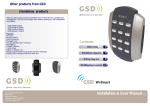
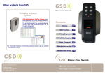
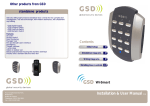
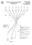
YOUR SECURITY IS OUR PRIORITY
Other products from GSD
“Wireless Network
System”
GSD Wi-Enterprise/Wi-Plus System is the
next generation in access control solutions.
It provides a Wireless Network throughout
the premises, giving the convenience and
security of a fully networked system for a
fraction of the cost.
Contents
Operation Instructions
2
Installation Diagrams
6
Wiring Diagrams
8
Quick Reference
13
Administration Notes 14
For more information on the Wireless Network System visit our website
www.globalsecurity.ie
Global Security Devices Ltd: No.3 Broomhill Business Complex, Tallaght,
Dublin 24, Ireland, Phone: +353 (1) 524 2691, Email: [email protected]
www.globalsecurity.ie
2 door digital keypad
Installation & User Manual
V2.02
Operation Instructions
2
Operation Instructions
Technical Specs
Power Supply
Current consumption
Current consumption with load (max)
Relay Contact Rating
Operating Temperature
Moisture Resistance
Dimensions - Flush Mount
- Surface Mount
Number of Users
12 - 24V AC or DC
100mA
130mA
5 Amps /240V ac
- 20 C to +60 C
IP 67
W. 87mm D. 21mm H. 119mm
W. 87mm D. 35mm H. 119mm
50
3
Adding and Removing User PINs
Code Description
01 Add a Standard User/Toggle User/Manager User PIN to Door 1
02 Add a Standard User/Toggle User/Manager User PIN to Door 2
03 Remove any User PIN
Example: To Add User PIN ‘5656' to Door 1..
X key then
Engineer
Code
+
Code = 01
+
PIN = 5656
+
Example: To Remove User PIN ‘4545’ from any door..
Factory Default PIN codes
X key then
Engineer
Code
The following PIN codes are the Factory Default Settings:
- User PIN ‘1111’ will grant access on door 1
- User PIN ‘2222’ will grant access on door 2
- The Default Engineer code is ‘6666’
Note: These User PINs (’1111’,’2222’) are deactivated when the first User PIN
is added to the keypad.
+
Code = 03
+
PIN = 4545
+
Example: To Add Toggle User PIN ‘1234’ to Door 2..
X key then
Engineer
Code
+
Code = 02
+
PIN = 1234
1 = Toggle User
+
1
Example: To Add Manager User PIN ‘5678’ to Door 2..
2 = Manager User
Restoring Factory Settings
Code
55
X key then
Engineer
Code
Description
Restore Factory Default Settings
Example:
X key then
Engineer
Code
+
Code = 55
+
Note: If Engineer code is lost, Remove the Security Caps (see Page 7) and
hold down the X key during power-up and enter the default Engineer
code ‘6666’ immediately. This will restore the factory settings.
+
Code = 02
+
PIN = 5678
+
2
4
Operation Instructions
Operation Instructions
5
Table 1
Changing Relay Times and Engineer Codes
Code
10
11
12
13
14
15
Description
Change the Number of PIN Digits
Change the Engineer Code
Change the Relay Active Time Door 1
Change the Door Ajar Time
Change the Guest Buzzer Time
Change the Relay Active Time Door 2
Default Settings
4 digit PIN (4,5,6 only)
6666
5 seconds (0-255)
30 seconds (2-255)
3 seconds (1-10)
5 seconds (0-255)
Note: The Number of PIN digits can not be reduced once a User Pin has
been added.
Input 3
Output 1
Output 2
0
Door 1 Exit
Default Button
Door 1
Contact
Interlock
I/P
Alarm/
Buzzer
Interlock
O/P
Page 8
1
Door 1 Exit
Button
Door 1
Contact
Interlock
I/P
Follow
Relay 1
Interlock
O/P
Page 8
2
Door 1 Exit
Button
Door 1
Contact
Alarm Panel
I/P
Alarm/
Buzzer
Alarm Panel
O/P
Page 9
3
Door 1 Exit
Button
Door 1
Contact
Fire Alarm
Override
Follow
Relay 1
Alarm/
Buzzer
Page 10
4
Door 1 Exit
Button
Door 1
Contact
Door 2
Exit Button
Follow
Relay 1
Alarm/
Buzzer
Page 11
5
Door 1 Exit
Button
Door 1
Contact
Door 2
Exit Button
Follow
Relay 1
Follow
Relay 2
Page 11
Example: To Change the Engineer Code..
X key then
Engineer
Code
+
Code = 11
+
New
Engineer
Code
Example: To Change the Relay Active Time to 14 seconds..
X key then
Engineer
Code
+
Code = 12
+
Time = 14
+
Example: To Change the Relay Active Time to a 200msec pulse..
X key then
Engineer
Code
+
Code = 12
+
Time = 0
+
Input 1
Turning Features ON or OFF
Code
20
21
22
23
24
25
26
27
28
Description
Set Silent Operation on/off
Set Ajar Alarm on/off
Set Guest Button on/off
Set Duress codes on/off
Set Toggle Relay on/off
Set Door Forced Alarm on/off
Set Anti-Tail Gate on/off
Set Constant Backlight on/off
Set Invalid PIN Lockout on/off
Note: 0 = Off
Changing Input/Output Options
Wiring
Diagrams
Input 2
Option
Default Settings
Off
On
On
Off
On
On
Off
On
On (3 Retries)
1= On
Example: To Set the Backlight to always stay ON...
Code Description
30 Change the Input and Output Options
X key then
Engineer
Code
+
Code = 27
+
ON = 1
Example: To Set the Backlight to stay ON for 10 seconds only after a key press...
Example:
X key then
Engineer
Code
+
Code = 30
+
Enter 0-5
Refer to
Table 1
X key then
Engineer
Code
+
Code = 27
+
OFF = 0
6
Installation Diagrams
Installation Diagrams
7
Flush Mounting
Fix Surface Mount Collar to
wall, ensure arrow is
pointing upwards
Keypad is mounted to pattress box using security
screws provided. Both Security Caps are
then clipped onto Keypad.
Surface Mounting
Fix Surface Mount Collar to wall (as above).
After wiring is complete, Keypad may
then be screwed to Surface Mount Collar
using security screws provided.
Both Security Caps are then
clipped onto keypad
To attach Security Caps hook tabs
into holes and push on.
To release Security Caps push a
screwdriver into slots on the side
and pull forward.
To attach Security Caps hook tabs
into holes and push on.
8
Wiring Diagrams
Wiring Diagrams
Wiring Diagrams for Door 1 with
Interlock connections
9
Wiring Diagrams for Door 1
with Alarm Panel Connections
Door 1
Exit Button
Only the Manager User can
activate/deactivate the Alarm
Panel. When the Alarm Panel is
activated all other users are
locked out.See notes on Page 12
for explanation of feature.
Door 1 Exit Button
12V Linear
Power supply
0V
Door 1
Contact
12V
0V
12V Linear
Power supply
Door 1
Contact
12V
12V
IP1
IP2
0V
OP1
NO
COM TAMP
TAMP
NC
0V
Varistor
12V
Door MagLock
Always connect a
varistor between a
solid ground OV and
the NC for a maglock.
Volt Free
Tamper Contacts
1 and 2
Varistor
Sounder
Or
Follow
Relay 1
Interlock OP to Interlock IP
on 2nd Door
12 - 24 VAC
0V
12V
NC2
COM
NO2
IP3
OP2
NC2
COM
NO2
IP3
OP2
Varistor
12V
IP1
IP2
0V
OP1
NO
TAMP
COM
TAMP
NC
Interlock IP from Interlock OP
on 2nd Door
12V
0V
NO
COM
NC
Door MagLock
Volt Free
Tamper Contacts
1 and 2
Always connect a
varistor between a
solid ground OV and
the NC for a maglock.
Arm Alarm Input
12 - 24 VAC
Varistor
Arm Output (N/O)
12V
0V
NO
COM
NC
Common OV from the Intruder Alarm Panel
and the OV from the Keypad to avoid
any ground loop issues.
12 - 24 VAC
12 - 24 VAC
Wiring for StikeLock only using 12 - 24VAC supply
0V
Note: All OV shown in the diagram are connected
to OV at the back of the keypad terminal block.
Wiring for StikeLock only using 12 - 24VAC supply
0V
Note: All OV shown in the diagram are connected
to OV at the back of the keypad terminal block.
10
Wiring Diagrams
Wiring Diagrams
Wiring Diagrams for Door 1 and
Fire Alarm Override
12V Linear
Power supply
11
Wiring Diagrams for Door 1 and Door 2
Door 1
Exit Button
12V Linear
Power supply
Door 1 Exit Button
0V
0V
Door 1
Contact
Door 1
Contact
12V
12V
Varistor
Follow
Relay 1
NC2
COM
NO2
IP3
OP2
Varistor
0V
12V
IP1
IP2
0V
OP1
NO
COM TAMP
TAMP
NC
Volt Free
Tamper Contacts
1 and 2
Door MagLock
12V
Always connect a
varistor between a
solid ground OV and
the NC for a maglock.
0V
Follow
Relay 1
NC2
COM
NO2
IP3
OP2
12V
IP1
IP2
0V
OP1
NO
TAMP
COM
TAMP
NC
Volt Free
Tamper Contacts
1 and 2
Door MagLock
Always connect a
varistor between a
solid ground OV and
the NC for a maglock.
12V
Door 2 Exit
button
Fire Alarm
Panel
12 - 24 VAC
Varistor
Sounder
12V
0V
NO
COM
NC
When the fire alarm
is activated (0V removed
from IP3) the door will
be opened
0V
Common OV from the Fire Alarm Panel
and the OV from the Keypad to avoid
any ground loop issues.
12 - 24 VAC
Wiring for StikeLock only using 12 - 24VAC supply
0V
Note: All OV shown in the diagram are connected
to OV at the back of the keypad terminal block.
12 - 24 VAC
Varistor
12V
0V
NO
COM
NC
Sounder
Or
Follow
Relay 2
0V
12 - 24 VAC
Wiring for StikeLock only using 12 - 24VAC supply
0V
Note: All OV shown in the diagram are connected
to OV at the back of the keypad terminal block.
Quick reference
12 Operation Instructions
Notes:
Invalid PIN Lockout – Entering an invalid PIN 3 times will lockout the keypad for
15 seconds. All lights will flash during this time. Turning this feature off reduces the
security of the keypad.
Number of PIN Digits – The number of digits each User PIN will contain.(4 or 5 or 6).
The number of digits can not be reduced after a User PIN has been added.
If the number of PIN digits is increased then add leading Zeros to existing PIN’s.
E.G if increasing PIN digits from 4 to 5 then existing PIN code ‘1234’ changes to
‘01234’
Relay Active Time – This is the amount of time the relay will remain active. Entering
0 for the relay active time will generate a 200millisecond pulse .
Ajar Alarm – This alarm will activate if the door is open longer than the Door Ajar Time.
Door Forced Alarm – This alarm will activate if the door contact is forced open.
Anti-Tail Gate – If this option is set, the door relay time is shortened to 2 seconds.
Guest Button - If this option is set, then the tick key can be used to sound the buzzer.
Silent Operation - If this option is set, then all audible tones are silenced.
Duress codes - If this option is set, the door will open but the alarm will be activated if
the duress PIN code is entered. (duress PIN code is the code above the user PIN code
e.g. user code=8888 then duress code=8889).
Toggle Relay - If this option is set, then the door will remain open or closed on each PIN
entry for a Toggle User.
Manager User – If the Alarm Panel option is setup using the IO options then only the
Manager User will be granted access if the alarm is set.
The Manager User is the only user that can activate or deactivate the
Alarm Panel.The RED light Flashes to indicate the Alarm Panel is set.
The Manager User must press the ‘tick key’ and enter a PIN code to activate
the Alarm Panel.
To deactivate the Alarm Panel the Manager user enters a PIN code.If the Alarm
is deactivated then the Manager User operates as a standard user.
Quick Reference - Menu Codes
Code
Description
Default Settings
01
Add a User PIN to Door 1
1111
02
Add a User PIN to Door 2
2222
03
Remove a User PIN
10
Change the Number of PIN Digits
11
Change the Engineer Code
12
Change the Relay Active Time Door 1
5 seconds (0-255)
13
Change the Door Ajar Time
30 seconds (2-255)
14
Change the Guest Buzzer Time
3 seconds (1-10)
15
Change the Relay Active Time Door 2
5 seconds (0-255)
20
Set Silent Operation on/off
Off
21
Set Ajar Alarm on/off
On
22
Set Guest Button on/off
On
23
Set Duress codes on/off
Off
24
Set Toggle Relay on/off
On
4 digit PIN (4,5,6 only)
6666
25
Set Door Forced Alarm on/off
On
26
Set Anti-Tail Gate on/off
Off
27
Set Constant Backlight on/off
On
28
Set Invalid PIN Lockout on/off
On (3 Retries)
30
Change the Input and Output Options
0
55
Restore Factory Default Settings
3 Step Quick Setup :
Step 1, Restore Factory Default Settings..
X key then
Engineer
Code
+
Code = 55
+
Step 2, Change the Engineer Code..
X key then
Engineer
Code
+
Code = 11
+
Enter New
Engineer
Code
Step 3, Add a User PIN to Door 1 and then another User PIN to Door 2.
X key then
Engineer
Code
+
Code = 01 or 02
+
XXXX
(User PIN)
+
13
14 Administration Notes
Administration Notes
User Administrator
User
Location
1
2
3
4
5
6
7
8
9
10
11
12
13
14
15
16
17
18
19
20
21
22
23
24
25
User Name
PIN Number
User
Location
26
27
28
29
30
31
32
33
34
35
36
37
38
39
40
41
42
43
44
45
46
47
48
49
50
User Name
PIN Number
15