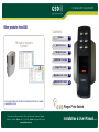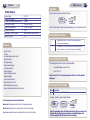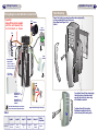
1
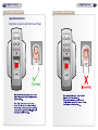
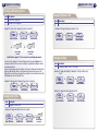
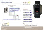
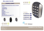
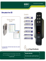
YOUR SECURITY IS OUR PRIORITY
Other products from GSD
Contents
“Wireless Network
System”
GSD Wi-Enterprise/Wi-Plus System is the
next generation in access control solutions.
It provides a Wireless Network throughout
the premises, giving the convenience and
security of a fully networked system for a
fraction of the cost.
For more information on the Wireless Network System visit our website
www.globalsecurity.ie
Global Security Devices Ltd: No.3 Broomhill Business Complex, Tallaght,
Dublin 24, Ireland, Phone: +353 (1) 524 2691, Email: [email protected]
www.globalsecurity.ie
Features
2
Best Practices
3
Wiring Diagrams
4
Installation Diagrams
5
Finger Placement
6
Operation Instructions
8
Administration Notes
10
Finger Print Switch
Operation Instruction:
Enter User Location xx and Present Finger
Administration Notes
Administration Notes
User Administrator
User
Location
User Name
Finger Reference
User
Location
11
12
13
14
15
16
51
52
53
54
55
56
21
22
23
24
25
26
61
62
63
64
65
66
31
32
33
34
35
41
42
43
44
45
46
User Name
Finger Reference
Note: Users are enrolled to the User Locations defined in the table above only.
YOUR SECURITY IS OUR PRIORITY
Other products from GSD
Contents
“Wireless Network
System”
GSD Wi-Enterprise/Wi-Plus System is the
next generation in access control solutions.
It provides a Wireless Network throughout
the premises, giving the convenience and
security of a fully networked system for a
fraction of the cost.
For more information on the Wireless Network System visit our website
www.globalsecurity.ie
Global Security Devices Ltd: No.3 Broomhill Business Complex, Tallaght,
Dublin 24, Ireland, Phone: +353 (1) 524 2691, Email: [email protected]
www.globalsecurity.ie
Features
2
Best Practices
3
Wiring Diagrams
4
Installation Diagrams
5
Finger Placement
6
Operation Instructions
8
Administration Notes
10
Finger Print Switch
Installation & User Manual
V2.02
2
Quick Reference
Features
3
Operation
Technical Specs
Power Supply
Current consumption
Current consumption with load (max)
Relay Contact Rating
Operating Temperature
Moisture Resistance
Dimensions - Surface Mount
Number of Users
Enter 2 digit User location and Present Finger
12V DC
70mA
100mA
5 Amps /240V ac
- 20 C to +60 C
IP 65
W. 87mm D. 35mm H. 160mm
35
Enter
User Loc
xx
Present Finger
Note: The Red Light on the Sensor Window will only turn on for valid user locations
Best Installation Practice
1
Features
+
Always Default the Door Control to Factory Settings before
commencing programming.
2
It is important to ensure that the varistor supplied with the Door
Control is fitted across the lock terminals on all installations.
Controls 1 Door
35 Users
Door Monitoring via Door Contact
Tamper Resistant
Easy Programming
Programmable Settings:
- Programming Code
- Relay Active Time
- Silent or Audible Operation
- Keypad Backlight
- Inputs/Outputs Options
Indoor/Outdoor Use - IP 65
Robust Polycarbonate Housing
Mounts onto Standard Electrical Patress Box
Factory Default PIN codes
The following PIN codes are the Factory Default Settings:
- The Default Engineer code is ‘6666’
- User PIN ‘1111’
Note: The User PIN ’1111’ is deactivated when the first User PIN is added to
the keypad.
Restoring Factory Settings
Code
55
Description
Restoring Factory Default Settings
Example: To Restore Factory Default Settings
Note: Engineering mode status Led indicators.
Amber Led flashing indicates that the unit is in Engineering mode.
Red Led flashing indicates user needs to enter data or present finger.
Engineering mode will time out automatically after 5 seconds of no activity.
Enter
Engineer
Code
+
Code = 55
+
Present Finger
to Confirm
Note: If programming code is lost, Remove the Security Caps (see page 5) and
hold down the 5 key during power-up and enter the default Engineer code
‘6666’ immediately. This will restore the factory settings.
4
Installation Diagrams
Wiring Diagrams
Flush Mounting
Wiring Diagrams with Interlock Connections
Important:
Always fit the varistor supplied
with the unit between the
lock terminals as shown
12V
Finger Print Switch is mounted to pattress box using security
screws provided. Both Security Caps are
then clipped onto Finger Print
Switch.
Sounder
Door
Exit Button
12V
NC
COM
NO
0V
12V
Varistor
Door MagLock
OP2
OP1
IP1
IP2
IP3
0V
Door
Contact
0V
Always connect a
varistor between a
solid ground OV and
the NC for a maglock.
12V Linear
Power supply
0V
12VDC
Varistor
NC
COM
NO
0V
12V
Interlock OP to
Interlock IP on
2nd Door
Interlock IP from
Interlock OP on
2nd Door
0V
0V
Note: All OV shown in the diagram are connected
to OV at the back of the keypad terminal block.
Wiring for StikeLock only using 12VDC supply
Table 1
Default
To re-attach Security Caps simply align
tabs into holes as shown above and
ease the Caps back into place using
a flat bladed screwdriver.
Input 1
Input 2
Input 3
Output 1
Output 2
Door Exit
Button
Door
Contact
Interlock
I/P
Interlock
O/P
Alarm/
Buzzer
Wiring
Diagrams
Page 5
To release Security Caps push a
flat bladed screwdriver into slots
on the side and pull forward gently.
5
6
Finger Placement
Finger Placement
Correct Finger Placement
Operation Instruction:
Enter User Location xx and then Present Finger
Incorrect Finger Placement
7
8
Operation Instructions
Operation Instructions
Enrolling and Removing Users
Changing Engineer Code
Code Description
1
Enrol a User Fingerprint
2
Remove a User Fingerprint
Code Description
4
Changing the Engineer Code
Example: To Change the Engineer Code to 1234
Example: To Enrol a Users Fingerprint in User Location 22
Enter
Engineer
Code
+
Amber LED flashes
+
Code = 1
Red LED flashes
User Loc. = 22
Red LED flashes
Enter
Engineer
Code
+
Amber LED flashes
+
Code = 4
1234
New Eng Code
+
Red LED flashes
Amber LED flashes
+
Present Finger
to Enroll
Present Finger
to Enroll
Note: Refer to pages 6 & 7 for correct/incorrect finger placement.
To enrol a users fingerprint , the users finger must be presented ‘twice’ to the
scansensor window. The scan sensor must get 2 good quality readings to have a
successful enrolment.
As per the steps above present the finger to the sensor window until confirmation
beep is heard and Red Led turns off momentarily. Remove and re-present the
finger for the second time to complete the enrolment. A successful enrolment will
be followed by an Access Granted Tone.
Example: To Remove Users Fingerprint from User Location 34
Enter
Engineer
Code
+
Amber LED flashes
+
Code = 2
Red LED flashes
User Loc. = 34
Amber LED flashes
Example: To Change the Relay Time to 15 seconds
Amber LED flashes
Code = 3
Red LED flashes
Example: To Toggle the Backlight to ‘Always On’ or ‘Only On after a Key
Press’
Enter
Engineer
Code
+
Seconds = 15
Red LED flashes
+
Present Finger
to Confirm
+
Amber LED flashes
Code = 6
1
+
Red LED flashes
Amber LED flashes
Example: To Toggle the Silent Operation On/Off
Amber LED flashes
Code Description
3
Changing the Relay Time
+
Code Description
6
Changing Backlight, Silent or Scan Mode
Enter
Engineer
Code
Changing Relay Time
Enter
Engineer
Code
Changing Settings
+
Code = 6
Red LED flashes
+
2
Amber LED flashes
9
Administration Notes
10 Administration Notes
User Administrator
User
Location
User Name
Finger Reference
User
Location
11
12
13
14
15
16
51
52
53
54
55
56
21
22
23
24
25
26
61
62
63
64
65
66
31
32
33
34
35
41
42
43
44
45
46
User Name
Finger Reference
Note: Users are enrolled to the User Locations defined in the table above only.