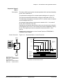
1
Chapter 4 - I/O Interfaces and Application Macros
Input and Output
Signals
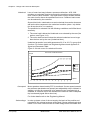
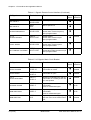
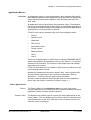
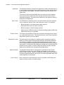
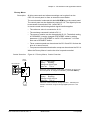
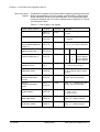
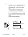
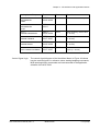
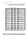
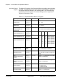
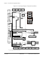
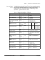
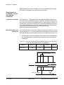
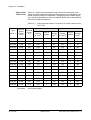
The default I/O signals of the Master/Follower Macro regarding opening/
closing the MCB, starting/stopping the drive, speed, control location, reference and actual values are shown in the following table. The corresponding parameters are listed as well. For further settings refer to
Appendix K - Signal and Parameter Table.
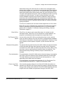
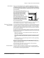
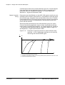
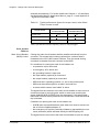
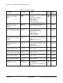
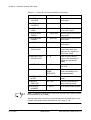
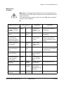
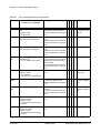
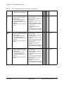
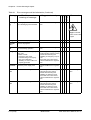
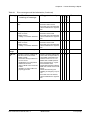
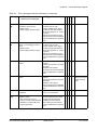
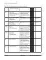
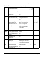
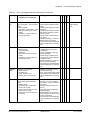
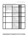
Table 4-12 Master/Follower Macro, I/O Signals
Digital Inputs/Outputs
Terminal
Parameter
Remarks
DI 2.1 START/STOP
IOEC 2
X11/1-2
11.01
1 = start
0 = stop
DI 2.2 DIRECTION
IOEC 2
X11/3-4
11.01
1 = forward
0 = reverse
DI 2.4
ACCEL/DECELERATION
RAMP 1/2
IOEC 2
X11/7-8
22.01
Selection of ramp time
0 = ramp time set 1
1 = ramp time set 2
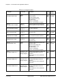
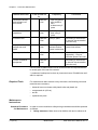
DI 2.5
CONST SPEED SEL 1
IOEC 2
X11/9-10
33.01
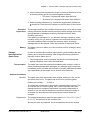
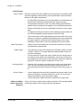
Sel1
Sel2
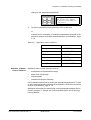
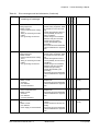
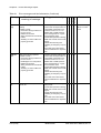
DI 2.6
CONST SPEED SEL 2
IOEC 2
X12/1-2
33.01
0
1
0
1
0
0
1
1
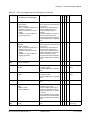
DI 1.8
DISABLE LOCAL
X301
X1-2
-
0 = control panel is enabled
1 = control panel is disabled
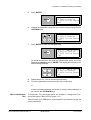
DI 2.8
/PROCESS STOP
IOEC 2
X12/5-6
16.01
Process stop or run enable
0 = drive will not start or stop if
running
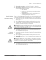
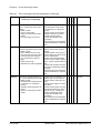
DI 2.7
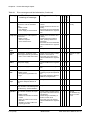
REMOTE ORD MCB
CLOSE
IOEC 2
X12/3-4
11.04
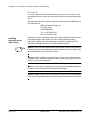
pulse -> 1 = command for closing the main circuit breaker
DI 2.13
REMOTE ORD MCB
OPEN
IOEC 2
X13/5-6
11.04
pulse -> 1 = command for opening the main circuit breaker
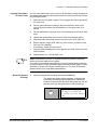
DI 2.9
MCB IS OPEN
IOEC 2
X12/7-8
21.06
Feedback from MCB
0 = MCB is open
1 = MCB is closed
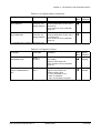
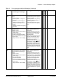
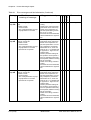
DO 2.5
/MCB ORD OPEN
IOEC 2
X25/2-3
21.05
Command to open the MCB
pulse -> 0 = MCB open 1
DO 2.6
MCB ORD CLOSE
IOEC 2
X26/2-3
21.05
Command to close the MCB
pulse -> 1 = MCB close
ACS 1000 User’s Manual, Rev. C
3BHS102769
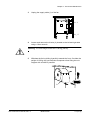
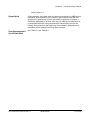
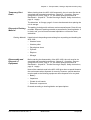
Selection
Analog Ref.
Const. Speed 1
Const. Speed 2
Const. Speed 3
4-35 (of 38)