1
fishcamp engineering
FPCI-DIO - Digital Input/Output Card for PCI bus
© fishcamp engineering, 1996
Revision - 28 April, 1996
Limited Warranty
The FPCI-DIO interface hardware is warranted to be free from defects in materials and
workmanship for a period of one year from date of shipment from fishcamp engineering. Defects caused
by misuse, abuse, or shipment are not covered.
Defective equipment that is subject to this limited warranty will be repaired or replaced at the
option of fishcamp engineering if we are notified during the warranty period. The customer must obtain
a Return Material Authorization (RMA) number before returning any equipment. Shipping costs from
fishcamp engineering will be paid by fishcamp engineering. Equipment should be packaged in the
original shipping container if possible, and the RMA number must be clearly marked on the outside of
the package.
The information provided in this manual is believed to be correct, however fishcamp
engineering assumes no responsibility for errors contained within. The software programs are provided
"as is" without warranty of any kind, either expressed or implied.
No other warranty is expressed or implied. Fishcamp engineering shall not be liable or
responsible for any kind of damages, including direct, indirect, special, incidental, or consequential
damages, arising or resulting from its products, the use of its products, or the modification to its
products. The warranty set forth above is exclusive and in lieu of all others, oral or written, express or
implied.
The information covered in this manual is subject to change without notice.
Contents
Contents
i
Chapter 1 - Introduction . . . . . . . . . . . . . . . . . . . . . . . . . . . . . . . . . . . . . . . . . . . . . . . . . . . .
1.0 Introduction . . . . . . . . . . . . . . . . . . . . . . . . . . . . . . . . . . . . . . . . . . . . . . . . . . . . .
1
2
Chapter 2 - Installation . . . . . . . . . . . . . . . . . . . . . . . . . . . . . . . . . . . . . . . . . . . . . . . . . . . . . 3
2.0 Hardware Installation . . . . . . . . . . . . . . . . . . . . . . . . . . . . . . . . . . . . . . . . . . . . . 4
2.1 Software Installation . . . . . . . . . . . . . . . . . . . . . . . . . . . . . . . . . . . . . . . . . . . . . . 4
2.2 Checkout . . . . . . . . . . . . . . . . . . . . . . . . . . . . . . . . . . . . . . . . . . . . . . . . . . . . . . . . 4
Chapter 3 - Hardware . . . . . . . . . . . . . . . . . . . . . . . . . . . . . . . . . . . . . . . . . . . . . . . . . . . . . .
3.0 Overview . . . . . . . . . . . . . . . . . . . . . . . . . . . . . . . . . . . . . . . . . . . . . . . . . . . . . . . .
3.1 PCI Local Bus Interface Logic . . . . . . . . . . . . . . . . . . . . . . . . . . . . . . . . . . . . . . .
3.2 Port Logic . . . . . . . . . . . . . . . . . . . . . . . . . . . . . . . . . . . . . . . . . . . . . . . . . . . . . . .
3.3 Connector Pinouts . . . . . . . . . . . . . . . . . . . . . . . . . . . . . . . . . . . . . . . . . . . . . . .
8
9
9
10
13
Chapter 4 - Software . . . . . . . . . . . . . . . . . . . . . . . . . . . . . . . . . . . . . . . . . . . . . . . . . . . . . .
4.0 Software . . . . . . . . . . . . . . . . . . . . . . . . . . . . . . . . . . . . . . . . . . . . . . . . . . . . . . . .
17
18
Appendix A - MacOS Software Support . . . . . . . . . . . . . . . . . . . . . . . . . . . . . . . . . . . . .
A.1 Overview . . . . . . . . . . . . . . . . . . . . . . . . . . . . . . . . . . . . . . . . . . . . . . . . . . . . . .
A.2 Software Installation . . . . . . . . . . . . . . . . . . . . . . . . . . . . . . . . . . . . . . . . . . . .
A.3 Device Driver . . . . . . . . . . . . . . . . . . . . . . . . . . . . . . . . . . . . . . . . . . . . . . . . . .
A.3.1 OpenDriver Routine . . . . . . . . . . . . . . . . . . . . . . . . . . . . . . . . . . . .
A.3.2 CloseDriver Routine . . . . . . . . . . . . . . . . . . . . . . . . . . . . . . . . . . . .
A.3.3 Read Routine . . . . . . . . . . . . . . . . . . . . . . . . . . . . . . . . . . . . . . . . . . .
A.3.4 Write Routine . . . . . . . . . . . . . . . . . . . . . . . . . . . . . . . . . . . . . . . . . .
A.4 Error Codes . . . . . . . . . . . . . . . . . . . . . . . . . . . . . . . . . . . . . . . . . . . . . . . . . . . . .
A.5 Cookbook . . . . . . . . . . . . . . . . . . . . . . . . . . . . . . . . . . . . . . . . . . . . . . . . . . . . . .
A.6 FPCIManager Library . . . . . . . . . . . . . . . . . . . . . . . . . . . . . . . . . . . . . . . . . . . .
A.6.1 Overview . . . . . . . . . . . . . . . . . . . . . . . . . . . . . . . . . . . . . . . . . . . . . . .
A.6.2 FPCIManager Use . . . . . . . . . . . . . . . . . . . . . . . . . . . . . . . . . . . . . . .
A.6.3 FPCIManager Cookbook . . . . . . . . . . . . . . . . . . . . . . . . . . . . . . . . . .
19
20
21
21
22
22
23
26
29
30
35
35
35
35
FPCI-DIO Specifications . . . . . . . . . . . . . . . . . . . . . . . . . . . . . . . . . . . . . . . . . . . . . . . . . . .
45
ii
Contents
Chapter 1 - Introduction
Introduction
1
1.0 Introduction
The FPCI-DIO card is a parallel digital interface for personal computers supporting the PCI
expansion bus. It provides for 96 TTL compatible signal lines which may be configured, in groups of
eight, to act as either input or output signals. Interconnection between the user's circuitry and the FPCIDIO card is via three 50-pin ribbon cable headers on the card. Each of the connectors carries 32 signal
lines as well as ground reference and protected +5V power from the computer.
The FPCI-DIO card is compatible with Rev 2.1 of the PCI local bus specification. The PCI
implementation supports a +5 Volt only bus interface in a short card form factor. A full 32 bit interface
as well as on board FIFOs enables zero wait-state burst mode operation over the bus.
Software control of the FPCI-DIO card is facilitated by a device driver compatible with the
various operating systems supported. Currently the MacOS and Windows 95 are the only operating
systems supported by fishcamp engineering. Contact fishcamp engineering for information on support
for other operating systems.
We have provided as much information as possible about the FPCI-DIO card so that users will
never be stymied in their development cycle because of the lack of relevant information. To this end we
have provided both schematic diagrams of the hardware logic on the card and software source code
listings of interface software shipped with the card. The user is encouraged to examine these documents
when more detail is needed on the architecture of the FPCI-DIO card.
2
Introduction
Chapter 2 - Installation
Installation
3
2.0 Hardware Installation
The card installation procedure you follow depends upon which model of computer you have.
For detailed installation instructions, please refer to the manual that came with your computer. The
card may be installed into any 32 bit PCI slot. The FPCI-DIO card operates from +5V only. It does not
support the 64 Bit nor +3.3V options in the PCI specification. The edge connector of the FPCI-DIO card
is keyed to prevent any installation errors in computers supporting these bus options.
Use a standard 50-Pin ribbon cable header to access the customer I/O signals. Carefully route
the ribbon cables though the card’s metal bracket and out of the access slot from the computer.
The FPCI-DIO card may be plugged into any PCI slot in the computer. The accompanying
software does not assume any particular slot. There are no switches nor jumpers to set on the card.
WARNING When handling the FPCI-DIO card, hold the card by its edges to avoid
touching any of the integrated circuits or the connector that plugs into the slot on the
main logic board of your computer. Make sure the power to the computer is off before
installation.
2.1 Software Installation
The various software drivers for the FPCI-DIO card are documented in the appendices of this
manual. Since each computer platform supported by the FPCI-DIO card will have a unique software
installation procedure, the reader should refer to the appendix of interest. Appendix A documents the
installation of the FPCI-DIO software driver for the MacOS. Windows95 software installation is
documented in Appendix B.
2.2 Checkout
This section describes the ‘FPCI-DIO Check’ program included on the distribution disks. This
program is used to verify the correct operation of the FPCI-DIO card in the computer. It also checks for
the proper installation of the required software for the card. It should be run after installing both the
FPCI-DIO card itself and the software driver for the card.
The operation of the ‘FPCI-DIO Check’ program is identical on each platform supported and
thus is documented here without reference to any particular computer platform’s specifics. Run the
application by double-clicking on the program’s icon. The ‘FPCI-DIO Check’ program’s icon looks like:
4
Installation
FPCI-DIO Check
Figure 1 - FPCI-DIO Check program icon.
The program will perform a test while launching in order to determine if the software for the
card has been properly loaded. If various software files are not found, the program will display an
error message informing the user of the problem. If there is a problem in this area the program will
then terminate. The reader should refer to the appendix detailing the software installation for the
particular platform being used if this error occurs.
If the software is properly installed, after the program starts, you will see the following
window displayed on the computer’s screen:
Figure 2 - FPCI-DIO Check Program Warning.
This message reminds the user that the test program will periodically drive the I/O signal
lines on the card during the performance of its test routines. Because of this the user should make sure
that nothing is connected to the I/O ports on the card before running this test.
Installation
5
The user should click the ‘OK’ button to dismiss the warning message’s window. Afterwards,
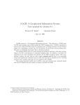
the program will display the main test window. This window will look as shown in figure 3.
Figure 3 - FPCI-DIO Check Program Main Window
Displayed in the center of the main program’s window, will be displayed a status line for each
FPCI-DIO card detected in the computer. The number of the slot for each card will be displayed as
well as the status of any test run on the particular card. On the beginning of each card’s status line is
displayed a check box which will allow you to select that particular card to be tested. Check the box
by clicking the mouse cursor within the box. Multiple cards may be selected before beginning the test.
After you have selected the desired card(s) to test, you must check the ‘Run Tests’ check box in
the upper right hand corner of the window. The program will then begin cycling through all of its test
routines for each card selected. Also in the upper right of the window are two status lines. One line
will display the total number of times the program has cycled through one complete set of tests for
each board selected. The other line, labeled as ‘Error count’ will display the total number of errors
detected since the test was begun. This count is a summary of all errors found on any of the boards
currently being tested.
The status line for the individual cards themselves will show any error relating to the
particular card in question. If no errors are detected for a particular card, then its status line will show
a ‘status- PASS’ message. Any other errors detected on the card will be displayed with a unique error
description for the particular error detected. If multiple errors were detected on a card, then only the
first error will be displayed.
6
Installation
During the course of running the test, the FPCI-DIO Check program will detect problems of a
hardware nature only. If any errors are detected, the card will have to be returned to fishcamp
facilities for replacement or repair. There are no user reparable components on the card.
Installation
7
Chapter 3 - Hardware
8
Hardware Overview
3.0 Overview
The FPCI-DIO card's logic is implemented on a 7" long PCI card. This 'half-length' card
should be capable of being used in any of the computer platforms which support the PCI interface. Only
+5 volt power is required by the card. The card is not compatible with the +3.3 volt subset of the PCI
specification. It supports 32 bit transfers over the PCI bus as well as a full 32 bit data path to the
customer I/O ports on the card.
Three memory spaces are mapped from the card into the memory space of the host computer via
the PCI base address registers on the FPCI-DIO card. The first memory space is mapped to respond to
either memory or I/O accesses and contains all of the PCI bus related configuration registers on the card.
The second memory space contains the I/O port registers and the port configuration register of the user
I/O ports on the FPCI-DIO card. The I/O port registers correspond to the I/O signal lines accessible via
the user I/O connectors. Simple memory READ and WRITE operations provide the mechanism by
which data is transferred between the host computer and the I/O ports. The third memory space is
allocated to give the host CPU access to the Expansion ROM on the card. All data paths on the card
are a full 32 bits wide with the exception of the Expansion ROM. Access to the ROM is performed via
an 8 bit data path.
The I/O signals from the card are made available to the user via three 50-pin ribbon cable
headers. They are referenced in the software as 'port0', 'port1', and 'port2'. The connectors are labeled
'PORT 0', 'PORT 1' and 'PORT 2' on the silkscreen on the printed circuit card. Each port/connector
carries 32 of the 96 signals supported by the FPCI-DIO card. Along with the 32 I/O signals are included
17 ground connections and protected +5v power from the host computer.
The +5v power can be used to power custom circuitry in the user's interface provided that the
limit of the computer's power supply is not exceeded. Each model of computer has its own power
specification and the user should consult the documentation for the particular model being used. In any
case, the +5v power lines made available to the user are protected with a single 1 Amp resettable fuse
in order to protect the computer incase of power shorts in the user's equipment. Therefore, maximum
combined current draw from all three customer I/O ports should be limited to 1Amp.
The resettable fuse used to protect the +5 volt customer power lines will latch into its high
impedance mode when tripped. It will remain in this mode once tripped. To reset the fuse, the user
will need to power off the computer for a short while and correct the fault condition before re-applying
power. The protector requires no manual resetting or replacement.
A total of seventeen ground connections are provided on each connector in order to help maintain
signal integrity in noisy environments or when using long cable runs. Each of the three connectors have
the same pinout thus simplifying interconnection to the user's equipment.
3.1 PCI Local Bus Interface Logic
The FPCI-DIO card implements a full 32-bit interface to the PCI local bus. The control logic
allows the FPCI-DIO card to respond as a slave only device on the PCI bus. Therefore, only host CPU
generated READ and WRITE operations are supported. The card cannot assume bus mastership nor
generate interrupts. Zero wait-state burst mode transfers are supported by means of on board FIFOs.
There is a separate FIFO for READ and WRITE operations to the board. Each FIFO is sixteen longwords deep.
Hardware Overview
9
Normally, the user's program simply READs from or WRITEs to the addresses assigned to the
I/O port registers on the card. In this way the user may acquire the state of the input signals or write
new values to the output signals.
The addresses of the I/O port registers on the FPCI-DIO card are not constant values. This is
because the PCI Bus specification requires that interface card address values be dynamically assigned
by the host computer during the boot-up process. The FPCI-DIO card defines three memory regions on
the card which are to be dynamically assigned by the host system.
The first memory region is that which contains the PCI configuration space registers. This
region is 128 bytes deep and can be accessed via either a memory access or an I/O cycle access over the
PCI Bus. The PCI Base address register at location 10h of the configuration space is used to map these
registers for memory cycle accesses. The PCI Base address register at location 14h of the configuration
space is used to map these registers for I/O cycle accesses. Normally these registers are not of any
concern to the application driving the FPCI-DIO card. They are used primarily during the host system
boot-up procedure.
The second memory region on the FPCI-DIO card is where the Expansion ROM is mapped. This
region is 128K bytes in size and can be accessed via a memory cycle access over the PCI Bus. The PCI
Base address register at location 30h of the configuration space is used to map the expansion ROM for
memory cycle accesses. The Expansion ROM is used to store two vital pieces of data. The first data
block is for the logic fuse map to a field programmable gate array on the card. This gate array
implements much of the hardware logic for the FPCI-DIO card. Normally the fuse map data is used to
configure the logic on the card upon power-up and is not normally read by the host CPU. It is accessible
by the host CPU for diagnostic purposes during board manufacture. The second data block is for driver
code for the card. This driver provides for card initialization under various operating systems.
Currently supported are an Open Firmware and PC-AT compatible data structures. The Expansion ROM
memory space on the FPCI-DIO card is mapped as a byte-wide interface to the PCI Bus. This was done
in order to save on the cost to manufacture the card. It does not compromise performance during the
normal operation of the card since the driver code within the Expansion ROM is read into system
memory upon startup and then executed out of system memory after that. All I/O operations to the user
ports on the card are always performed in full 32 bit operations.
The last memory region on the FPCI-DIO card is the area where the user I/O port and port
configuration register exist. This region is 64K bytes in size and can be accessed via a memory cycle
access over the PCI Bus. The PCI Base address register at location 18h of the configuration space is used
to map this region for memory cycle accesses. There are four memory registers in this group which may
be written or read by the host computer’s processor. Three of these registers are assigned to the I/O
ports on the card. One register for each port. These port registers are a full 32 bits wide with a bit
corresponding to its respective signal on the I/O port. Because the FPCI-DIO card’s PCI interface logic
implements the full 32 bit interface, all of the signals on a port may be accessed in a single memory
reference operation by the processor. The fourth register is a control register which, among other
things, allows the user to specify the direction of the I/O signals. Only 14 bits are defined in the
control register. For more information on the control register please refer to section 3.2.
3.2 Port Logic
As mentioned in the previous section, there are four user I/O registers defined in the memory
map of the FPCI-DIO card. The first register is a control register which is located at address offset
10
Hardware Overview
0xC000 from the base address register at location 18h. The control register is cleared to all zero's upon
restart of the computer or whenever the driver for the card is opened.
Only 14 of the bits are valid within the control register. The 12 least significant bits control
the direction of the I/O port signals on the card. Each of the three I/O ports on the FPCI-DIO card
provide for 32 user signal lines on its interface. These 32 signal bits are grouped into four groups of eight
bits (four bytes). Within each byte the user has control over the direction of the signal flow within
that particular byte. All eight of the signals in the byte will assume the same signal direction flow.
The way the user specifies the signal direction is by that byte's corresponding direction control bit in
the control register. There are 12 direction control bits defined in the register. One for each of the 12
bytes or 96 signal lines provided for by the FPCI-DIO card. A '1' written into the data direction bit
will set the 'output' mode for that particular byte. Conversely, a '0' programmed into the data
direction bit will set that byte to the 'input' mode of operation. The FPCI-DIO card will clear all of
the bits in the control register each time the host computer is restarted. Therefore all 96 signal lines
will be placed in the 'input' mode of operation and the card will not drive any of the I/O signals. The
driver's initialization code is responsible for clearing all of the registers on the card.
Bit #
31 3 0 2 9 28 27 26 2 5 2 4 23 22 21 2 0 1 9 18 17 16 1 5 1 4 13 12 11 1 0
9
8
7
6
5
4
3
2
1
0
La tch ed _da ta
Te st
Port 2
Port 1
Port 0
Legend
Mo de
Di rec ti on
11
Di rec ti on
10
Di rec ti on
9
Di rec ti on
8
Di rec ti on
7
Di rec ti on
6
Di rec ti on
5
Di rec ti on
4
Di rec ti on
3
Di rec ti on
2
Di rec ti on
1
Di rec ti on
0
Default Value = 0x0000 (power-up)
Direction Bits:
0 = signal line defined as an INPUT
1 = signal line defined as an OUTPUT
Test Mode:
0 = Normal Operation
1 = Test mode operation
Latched_data:
0 = Data NOT latched
1 = Data LATCHED
Direction 11 - Port 2 Byte 3
Direction 10 - Port 2 Byte 2
Direction 9 - Port 2 Byte 1
Direction 8 - Port 2 Byte 0
Direction 7 - Port 1 Byte 3
Direction 6 - Port 1 Byte 2
Direction 5 - Port 1 Byte 1
Direction 4 - Port 1 Byte 0
Direction 3 - Port 0 Byte 3
Direction 2 - Port 0 Byte 2
Direction 1 - Port 0 Byte 1
Direction 0 - Port 0 Byte 0
Figure 4 - Control Register Bit definitions.
Hardware Overview
11
The other two bits defined in the control register are used to define certain modes of operation
of the FPCI-DIO card. The 'latch_data' bit is used to enable a data sampling clock on the card. This
clock is used to latch the state of the input signals being acquired by the FPCI-DIO card from the user's
equipment before being read by the host CPU. Even though it is true that any data acquisition program
running on the host computer will usually be sampling the user's inputs asynchronously to any events in
the user's equipment, it is sometimes advantageous to enable the 'latch_data' bit in the control register
on the FPCI-DIO card. This is usually done if the FPCI-DIO card will be sampling very fast changing
data or when the input signal's transition time is very slow. When the 'latch_data' bit is set in the
control register, the FPCI-DIO card will clock the input data into an intermediate register with a
sample clock signal prior to sending the data on to the host computer’s processor during a 'read'
operation. This input latch has a much smaller sample window than the normal input logic on the card
and thus will be better able to correctly sample data during these periods of uncertainty. The
'latch_data' bit is cleared to '0' upon restart of the host computer.
The last bit defined in the control register is a bit which is used to facilitate testing of the
FPCI-DIO board during its manufacture at the fishcamp facilities. Normally this bit is left in the
cleared ('0') state during operation. The user should never set this bit to a '1' during operation of the
FPCI-DIO card. This bit is cleared upon restart of the host computer via the card’s driver
initialization code.
The remaining three user registers defined in the memory map of the FPCI-DIO card correspond
to the three I/O ports of the card. It is thru these three registers that the user's program can input or
output data from the FPCI-DIO card.
Each port is addressed from the software by means of long-word memory READs and WRITEs to
that port's register memory location on the FPCI-DIO. Each of the 32 bits in the long-word corresponds
to a particular signal on the connector of the I/O port for that register. Since the FPCI-DIO card is
designed as a full 32 bit PCI Bus interface, all 32 signals lines may be written or read in a single longword memory operation from the host computer’s processor. The hardware logic on the FPCI-DIO card
actually requires that only long-word operations to be performed. The software drivers provided by
fishcamp engineering enforce this requirement. The following table lists the user I/O port mapping of
the card:
Register Memory Address Offset
0x8000
0x8010
0x8020
Port Connector
Port 0
Port 1
Port 2
Figure 5 - I/O Register Port Mapping.
When writing applications programs which drive the FPCI-DIO card, the programmer should
keep in mind that the FPCI-DIO hardware conforms to the PCI Bus specification’s ‘little-endian’ data
format. The byte lane alignment of the data may be an issue to the programmer depending upon which
host computer platform the FPCI-DIO board is being used. The fishcamp engineering drivers for the
various computer platforms supported automatically take care of any endian conversion required by the
platform.
12
Hardware Overview
3.3 Connector Pinouts
Each of the three ports on the FPCI-DIO card has its signals made available for the customer's
use via a standard 50-pin ribbon cable header. These headers have contacts made up of 25mil square
pins. There are two rows of 25 pins each for a total of 50 pins. The pin spacing is a standard 100 mils.
The numbering of the pins is as shown in figure 6. For clarity, only one port connector is shown. All
three port connectors have the same numbering.
PORT2
1
49
2
50
Figure 6 - I/O port pin numbering.
(The view shown is from the component side of the FPCI-DIO card.)
Each of the connectors contains all of the signals for a single port on the FPCI-DIO card or 32
signal lines. The remaining pins carry logic ground (17 pins) and protected +5V power (1 pin) from the
computer's power supply. All three connectors have the same pinout defined for the signals on their
respective ports.
Hardware Overview
13
I/O Connector Pin
Port 0 - 1
Port 0 - 2
Port 0 - 3
Port 0 - 4
Port 0 - 5
Port 0 - 6
Port 0 - 7
Port 0 - 8
Port 0 - 9
Port 0 - 10
Port 0 - 11
Port 0 - 12
Port 0 - 13
Port 0 - 14
Port 0 - 15
Port 0 - 16
Port 0 - 17
Port 0 - 18
Port 0 - 19
Port 0 - 20
Port 0 - 21
Port 0 - 22
Port 0 - 23
Port 0 - 24
Port 0 - 25
Port 0 - 26
Port 0 - 27
Port 0 - 28
Port 0 - 29
Port 0 - 30
Port 0 - 31
Port 0 - 32
Port 0 - 33
Port 0 - 34
Port 0 - 35
Port 0 - 36
Port 0 - 37
Port 0 - 38
Port 0 - 39
Port 0 - 40
Port 0 - 41
Port 0 - 42
Port 0 - 43
Port 0 - 44
Port 0 - 45
Port 0 - 46
Port 0 - 47
Port 0 - 48
Port 0 - 49
Port 0 - 50
Signal
Port 0 - Data Bit 0
+5V
Port 0 - Data Bit 1
Ground
Port 0 - Data Bit 2
Ground
Port 0 - Data Bit 3
Ground
Port 0 - Data Bit 4
Ground
Port 0 - Data Bit 5
Ground
Port 0 - Data Bit 6
Ground
Port 0 - Data Bit 7
Port 0 - Data Bit 8
Port 0 - Data Bit 9
Ground
Port 0 - Data Bit 10
Port 0 - Data Bit 11
Ground
Port 0 - Data Bit 12
Port 0 - Data Bit 13
Ground
Port 0 - Data Bit 14
Port 0 - Data Bit 15
Ground
Port 0 - Data Bit 16
Port 0 - Data Bit 17
Ground
Port 0 - Data Bit 18
Port 0 - Data Bit 19
Ground
Port 0 - Data Bit 20
Port 0 - Data Bit 21
Ground
Port 0 - Data Bit 22
Port 0 - Data Bit 23
Ground
Port 0 - Data Bit 24
Port 0 - Data Bit 25
Ground
Port 0 - Data Bit 26
Port 0 - Data Bit 27
Ground
Port 0 - Data Bit 28
Port 0 - Data Bit 29
Ground
Port 0 - Data Bit 30
Port 0 - Data Bit 31
Figure 7- Port 0 Pinouts.
14
Hardware Overview
I/O Connector Pin
Port 1 - 1
Port 1 - 2
Port 1 - 3
Port 1 - 4
Port 1 - 5
Port 1 - 6
Port 1 - 7
Port 1 - 8
Port 1 - 9
Port 1 - 10
Port 1 - 11
Port 1 - 12
Port 1 - 13
Port 1 - 14
Port 1 - 15
Port 1 - 16
Port 1 - 17
Port 1 - 18
Port 1 - 19
Port 1 - 20
Port 1 - 21
Port 1 - 22
Port 1 - 23
Port 1 - 24
Port 1 - 25
Port 1 - 26
Port 1 - 27
Port 1 - 28
Port 1 - 29
Port 1 - 30
Port 1 - 31
Port 1 - 32
Port 1 - 33
Port 1 - 34
Port 1 - 35
Port 1 - 36
Port 1 - 37
Port 1 - 38
Port 1 - 39
Port 1 - 40
Port 1 - 41
Port 1 - 42
Port 1 - 43
Port 1 - 44
Port 1 - 45
Port 1 - 46
Port 1 - 47
Port 1 - 48
Port 1 - 49
Port 1 - 50
Signal
Port 1 - Data Bit 0
+5V
Port 1 - Data Bit 1
Ground
Port 1 - Data Bit 2
Ground
Port 1 - Data Bit 3
Ground
Port 1 - Data Bit 4
Ground
Port 1 - Data Bit 5
Ground
Port 1 - Data Bit 6
Ground
Port 1 - Data Bit 7
Port 1 - Data Bit 8
Port 1 - Data Bit 9
Ground
Port 1 - Data Bit 10
Port 1 - Data Bit 11
Ground
Port 1 - Data Bit 12
Port 1 - Data Bit 13
Ground
Port 1 - Data Bit 14
Port 1 - Data Bit 15
Ground
Port 1 - Data Bit 16
Port 1 - Data Bit 17
Ground
Port 1 - Data Bit 18
Port 1 - Data Bit 19
Ground
Port 1 - Data Bit 20
Port 1 - Data Bit 21
Ground
Port 1 - Data Bit 22
Port 1 - Data Bit 23
Ground
Port 1 - Data Bit 24
Port 1 - Data Bit 25
Ground
Port 1 - Data Bit 26
Port 1 - Data Bit 27
Ground
Port 1 - Data Bit 28
Port 1 - Data Bit 29
Ground
Port 1 - Data Bit 30
Port 1 - Data Bit 31
Figure 8 - Port 1 Pinouts.
Hardware Overview
15
I/O Connector Pin
Port 2 - 1
Port 2 - 2
Port 2 - 3
Port 2 - 4
Port 2 - 5
Port 2 - 6
Port 2 - 7
Port 2 - 8
Port 2 - 9
Port 2 - 10
Port 2 - 11
Port 2 - 12
Port 2 - 13
Port 2 - 14
Port 2 - 15
Port 2 - 16
Port 2 - 17
Port 2 - 18
Port 2 - 19
Port 2 - 20
Port 2 - 21
Port 2 - 22
Port 2 - 23
Port 2 - 24
Port 2 - 25
Port 2 - 26
Port 2 - 27
Port 2 - 28
Port 2 - 29
Port 2 - 30
Port 2 - 31
Port 2 - 32
Port 2 - 33
Port 2 - 34
Port 2 - 35
Port 2 - 36
Port 2 - 37
Port 2 - 38
Port 2 - 39
Port 2 - 40
Port 2 - 41
Port 2 - 42
Port 2 - 43
Port 2 - 44
Port 2 - 45
Port 2 - 46
Port 2 - 47
Port 2 - 48
Port 2 - 49
Port 2 - 50
Signal
Port 2 - Data Bit 0
+5V
Port 2 - Data Bit 1
Ground
Port 2 - Data Bit 2
Ground
Port 2 - Data Bit 3
Ground
Port 2 - Data Bit 4
Ground
Port 2 - Data Bit 5
Ground
Port 2 - Data Bit 6
Ground
Port 2 - Data Bit 7
Port 2 - Data Bit 8
Port 2 - Data Bit 9
Ground
Port 2 - Data Bit 10
Port 2 - Data Bit 11
Ground
Port 2 - Data Bit 12
Port 2 - Data Bit 13
Ground
Port 2 - Data Bit 14
Port 2 - Data Bit 15
Ground
Port 2 - Data Bit 16
Port 2 - Data Bit 17
Ground
Port 2 - Data Bit 18
Port 2 - Data Bit 19
Ground
Port 2 - Data Bit 20
Port 2 - Data Bit 21
Ground
Port 2 - Data Bit 22
Port 2 - Data Bit 23
Ground
Port 2 - Data Bit 24
Port 2 - Data Bit 25
Ground
Port 2 - Data Bit 26
Port 2 - Data Bit 27
Ground
Port 2 - Data Bit 28
Port 2 - Data Bit 29
Ground
Port 2 - Data Bit 30
Port 2 - Data Bit 31
Figure 9 - Port 2 Pinouts.
16
Hardware Overview
Chapter 4 - Software
Software Overview
17
4.0 Software
Although the hardware design of the FPCI-DIO card allows its use in any platform that has
PCI 2.1 compliant expansion slots, each platform will require a software driver specific to that
platform before the card can be utilized. This is because of the multitude of different processors which
may be used in the host machine (eg. PowerPC, x86, SPARC) and the various requirements of the
operating system being used (MacOS, Win95, OS/2, etc.).
This manual has the software support for each of the platforms supported described in the
appendixes in this manual. In addition to the documentation for the card’s driver, there may be
documentation for other software such as higher level code libraries or test utilities. Refer to the
appendix of interest for information on the desired platform support.
18
Software Overview
Appendix A - MacOS Software Support
MacOS Software Support
19
A.1 Overview
Programming of the FPCI-DIO card under the MacOS is facilitated by two software packages
included with the card. The first is the card’s driver code, which is a MacOS ‘NDRV’ code segment
stored in the file ‘FPCIDioDrvr’. This driver is loaded into memory from the computer’s hard disk and
executed during the boot-up routine of the computer. Once loaded, the driver routines may be called via
any programming language which supports calling the MacOS Device Manager. The driver contains
routines which allow the calling application to access all features of the FPCI-DIO card. Generally,
these routines are at a very low level and just provide basic functionality. The card device driver is
compiled to native code for the PowerPC processor.
The second software package included with the FPCI-DIO card is a Dynamic Link Library
stored in the file ‘FPCIManager’. This library contains other routines than those available in the
standard card device driver. These routines take care of many of the details of calling the MacOS
Device Manager and are at a much higher level than those of the standard card device driver. Because
of the ease of use and added functionality, the user will generally wish to call the routines in this
library rather than the card’s driver routines directly. The library is loaded into memory from disk
anytime an application calls one of its routines. The Library is compiled to native code for the
PowerPC processor.
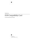
User Application
FPCIManager
FPCI-DIO card
FPCIDioDrvr
Extensions
System Folder
Figure A.1 - FPCI-DIO card Software relationships
20
MacOS Software Support
A.2 Software Installation
Copy the ‘FPCIDioDrvr’ and ‘FPCIManager’ file from the distribution floppy over to the
‘System’ folder on the MAC. These files’ icons look like:
FPCIDioDrvr
FPCIManager
Figure A.2 - FPCIDioDrvr and FPCIManager icons.
The system will ask you if you want the files placed in the ‘Extensions’ folder within the
‘System’ folder. Answer ‘yes’ to the question. The files will then be copied over to the extensions
folder. You will then have to re-boot the computer.
The ‘FPCIDioDrvr’ file is the actual software driver for the FPCI-DIO card. The driver gets
loaded by the MacOS upon restart. All I/O calls to the FPCI-DIO card are made thru this driver.
The ‘FPCIManager’ file is a SOMobjects™ Library file which implements a higher level API
than that provided by the ‘FPCIDioDrvr’ driver code. The library is a Dynamic Link Library which is
loaded only when needed by an application. The ‘FPCIManager’ makes all of its calls to the FPCI-DIO
card hardware via the standard calls provided by the ‘FPCIDioDrvr’ code. To take advantage of the
routines provided for by the ‘FPCIManager’, you will have to have SOMobjects™ previously loaded on
your computer. SOMobjects™ is Apple Computer’s implementation of IBM’s SOMobjects ™ on the
Macintosh. SOMobjects ™ is a multi-platform standard providing for system-level sharable objects in a
language-neutral way.
A.3 Device Driver
The driver is stored in a file that is normally located within the Extensions folder within the
System folder on the boot-up volume. It is read into memory and executed by the MacOS upon system
restart. The user may call the driver routines via any programming language which supports the
MacOS Device Manager. As long as the calling parameters are followed as directed, the routines will
execute regardless of what programming language was used to call them.
At boot-up time of the computer, the MacOS will match the driver up with the FPCI-DIO card
by means of the PCI Device and Vendor IDs stored in the configuration ROM of the card. When the
match is found, the MacOS will load the driver and call the driver’s Initialization and Open routines.
The driver is then available to be used by the user’s applications.
The driver has four primary routines which will need to be called by the user’s application
code. Two of the routines are used only for operating system housekeeping. They are the Open and
Close routines which need to be called at the start and finish respectively of your application. The
other two routines, the Read and Write routines, are used to do the actual data transfers between your
MacOS Software Support
21
program and the user I/O ports on the FPCI-DIO interface card.
Included on the distribution disk for the FPCI-DIO card is header file that contains some
definitions needed when writing your application program. The file is named ‘FPCIDioDriver.h’ and
defines certain data structures and constants which are used by the driver routines for the card.
The 'FPCIDioDrvrParam' structure is the single most important data type defined. Critical
information required during data transfer operations with the port registers are defined in this data
structure. This record is a 12 byte long data type with 3 distinct fields within it used. The format of
'FPCIDioDrvrParam' is:
struct FPCIDioDrvrParam {
UInt32
portNumber;
Nanoseconds updateDelay;
UInt32
errorCode;
};
/* -> the port number desired
/* -> # Nanoseconds between port writes
/* <- error code
*/
*/
*/
typedef struct FPCIDioDrvrParam FPCIDioDrvrParam, *FPCIDioDrvrParamPtr;
Figure A.3 - FPCIDioDrvrParam Structure Definition.
The use of the ‘FPCIDioDrvrParam’ structure will be documented below, in the sections
describing the Read and Write routines of the FPCIDioDrvr.
A.3.1 OpenDriver Routine
The standard MacOS OpenDriver routine can be used to open the FPCI-DIO card’s driver and
get it ready for subsequent data transfer operations. The PASCAL string "\p.FPCIDioDrvr" should be
used to specify the driver for the FPCI-DIO card. The following C language syntax should be used for
the call:
OSErr
short
err;
refNum;
err = OpenDriver(kDriverNamePString, &refNum);
This call will call the Open routine within the FPCIDioDrvr and return the ‘refNum’ to be
used for all succeeding calls to the driver. If more than one FPCI-DIO card is installed in the computer,
the OpenDriver call will select the first card that the MacOS finds. For information on using multiple
cards in the computer please refer to the section on the ‘FPCIManager’ software. If all goes well, the
execution of the OpenDriver routine will return ‘noErr’ in the ‘err’ variable. The constant
‘kDriverNamePString ‘ is defined in the ‘FPCIDioDriver.h’ include file.
A.3.2 CloseDriver Routine
After you are all finished making calls to the ‘FPCIDioDrvr’, you should close the driver with
a call to the MacOS CloseDriver routine. The ‘refNum’ parameter returned to you in the original
22
MacOS Software Support
OpenDriver call should be used in the parameter to this routine. The following C language syntax
should be used for the call:
OSErr
short
err;
refNum;
err = CloseDriver(refNum);
If all goes well, the execution of the CloseDriver routine will return ‘noErr’ in the ‘err’
variable. The ‘FPCIDioDrvr’ will be available for use by other application programs after the
execution of this call. Typically, you would make a call to this routine just before your application
terminates.
A.3.3 Read Routine
This routine is used for all INPUT data transfer operations. That is those operations which
transfer data FROM the I/O ports signals TO the host computer’s memory. Calls to the driver Read
routine can be made by either the PBReadSync or PBReadAsync MacOS routines. The prototype
definitions of these routines are specified in the MacOS header filer ‘Files.h’ as:
OSErr PBReadSync(ParmBlkPtr paramBlock);
and
OSErr PBReadAsync(ParmBlkPtr paramBlock);
The routines used will depend upon whether or not you wish to make the call synchronously or
asynchronously. Generally, you will make the call synchronously if you have very little data to send
and/or you want to make sure the data gets transferred before your application does anything else. The
PBReadSync routine should be called in situations such as this. The MacOS will enter the
‘FPCIDioDrvr’ and begin reading data from the interface into the computer’s main memory. It will
remain in a tight loop, continuing to transfer data until the byte count specified by the application is
met. Not until all the data has been transferred will the driver return control back to the application.
The PBReadAsync routine, on the other hand, should be used whenever you are transferring a large
amount of data or, because of the updateDelay parameter, the operation will take a significant amount
of time to complete. In this case, it will be wise to allow the application program to continue processing
while the data transfer completes. When a call to PBReadAsync is made, the ‘FPCIDioDrvr’ will
queue up the data transfer operation’s parameters, begin the transfer, and then return control back to
the calling application. The data transfer will continue in background until the byte count parameter is
finally met. At this time, a user specified completion routine will be executed in order to inform the
application that the data transfer has completed. The use of this kind of data transfer operation will
allow the application to provide the user a better experience than otherwise possible. In fact, under
certain conditions, the PBReadSync may make the computer appear to ‘hang’ to the user. The
PBReadAsync routine would never exhibit this kind of effect. Only one outstanding PBReadAsync
operation can be executing at a time. You must not start another transfer operation until any previous
one has fully completed.
Two data structures will need to be filled in and passed as parameters to the Read routine. The
first is an IOParam data structure which is defined in the ‘Files.h’ header file for the MacOS. A
Pointer to this data structure is what is passed as a parameter to either of the two routines. The second
data structure is an FPCIDioDrvrParam data structure that is defined in the ‘FPCIDioDriver.h’ file on
MacOS Software Support
23
the distribution disk.
The ‘IOParam’ data structure is where you specify all of the standard MacOS device manager
parameters. Six fields are parameters which must be filled in by the calling program before the call is
made to one of the Device Manager routines. You must return the refNum value which was returned to
you in the original OpenDriver call in the ‘ioRefNum’ field. This value will allow the application
program to specify a particular FPCI-DIO card in all subsequent driver calls.
The ‘ioBuffer’ parameter is user to specify a block of memory where all the data values read
from the desired I/O port will be stored. This memory block will need to be previously allocated by the
calling program before making the driver call. The ‘ioReqCount’ parameter is used to specify the
number of data words to read during the call. This value actually specifies the number of data bytes (8bit values) which are to be read. Remember that the FPCI-DIO card only supports 32 bit transfers so
the ‘ioReqCount’ field value must therefore be a multiple of 4 bytes. Any other value will result in an
error return from the driver call. The ‘ioPosMode’ field must be specified as the constant ‘ioMapBuffer’
and is a requirement imposed upon the driver by the MacOS. The last field in the ‘IOParam’ data
structure is the ‘ioCompletion’ field. This is where the calling application specifies the address of a
completion routine and is used whenever the driver call is performed asynchronously. This completion
routine will be called after all data words have been transferred by the driver. It is in this way that
the calling application will know when the previously specified transfer operation has finally
finished. You can specify the completion routine’s address by using the MacOS system call
‘NewIOCompletionProc’. If the driver call is to be made synchronously then you may specify NULL as
the value for the ‘ioCompletion’ field.
Several fields in the ‘IOParam’ data structure are used for return parameters. The ‘ioActCount’
field details the actual number of data bytes transferred during the driver call. Normally it will equal
the value specified in the ‘ioReqCount’ field upon entering the driver call. If it is not, then the driver
call encountered some sort of error and examination of the error return fields in the calling data
structured needs to be made to determine the nature of the error.
The ‘ioResult’ field will return any error code supplied by the MacOS. The possible error code
values are documented in the Inside Macintosh documentation from Apple Computer. The ‘errorCode’
field described below in the ‘FPCIDioDrvrParam’ data structure will contain the code for any errors
detected by the ‘FPCIDioDrvr’ software itself. Typically these will be errors in the calling parameter
list. Please see section A.4 for a list of these error codes.
The FPCIDioDrvrParam structure has 3 fields defined. Two of the fields are for parameters to
be defined by the calling application. The first of these parameters is the ‘ portNumber’ field. You must
specify in this field the desired register or I/O port you wish to read data from. Valid parameters are
one of the four port number constants defined in the ‘FPCIDioDriver.h’ header file:
// Defined board addresses
#define
#define
#define
#define
24
kFPCI_DIO_Port0
kFPCI_DIO_Port1
kFPCI_DIO_Port2
kFPCI_DIO_Cntrl
0x8000
0x8010
0x8020
0xC000
MacOS Software Support
The first three port numbers correspond to the three physical ports on the FPCI-DIO card. The
kFPCI_DIO_Cntrl constant actually refers to the configuration control register on the card. For
information on the configuration control register, please refer to section 3.2 on the port logic.
The second input parameter is the ‘updateDelay’ field. This field is used to specify a time
duration between consecutive read operations. This is useful when you want to input data continuously
from a given port over a period of time. The calling application will specify the number of port reads to
perform and then, in this ‘updateDelay’ field, the time in nanoseconds between these reads. The user
must understand that the timing of these data transfers is not precise. The ‘FPCIDioDrvr’ uses a
software interrupt timer mechanism to orchestrate the timing of the transfers. These software
interrupt timers have a lower priority than other items in the system such as hardware interrupts and
the execution of these interrupt routines will affect the precise time at which the software interrupt
timer routine is executed. Typically, the use of the ‘ updateDelay’ parameter is useful for time intervals
of a few microseconds or longer. You should specify a value of zero when you want to read data as fast
as possible. When a ‘updateDelay’ parameter of zero is specified in a call to PBReadAsync, the
‘FPCIDioDrvr’ will sit in a tight loop reading data but will periodically return control to the
application code so that the application will appear responsive to the user even during lengthy
transfer operations.
The third field in the ‘FPCIDioDrvrParam’ data structure is used for an error code return from
the driver. This fields is labeled ‘errorCode’ and will normally return zero if everything went fine
during the course of execution of the current driver call. If anything goes wrong, you should refer to the
code returned in this field to ascertain the nature of the problem. Please refer to section A.4 for a list of
possible error codes.
Once the ‘FPCIDioDrvrParam’ data structure is setup, you must insert a pointer to it in the
.ioMisc field of the IOParam. The following C language syntax illustrates the call to PBReadSync:
OSErr
FPCIDioDrvrParam
IOParam
Nanoseconds
long
long
status;
anFPCIDrvrParam;
anIOParam;
aNanosecondVar;
aLong;
actualTransferCount;
status = noErr;
// assume no error
//
// Setup the MacOS and FPCIDioDrvr parameter blocks
//
CLEAR(anIOParam);
// the CLEAR macro simply zeros all fields
CLEAR(anFPCIDrvrParam);
anIOParam.ioRefNum = refnum;
// was a return value from the OpenDriver call
anFPCIDrvrParam.portNumber = kFPCI_DIO_Port0; // port 0
aNanosecondVar.hi = 0;
aNanosecondVar.lo = 0;
// read data as fast as possible
anFPCIDrvrParam.updateDelay = aNanosecondVar;
anIOParam.ioMisc = (Ptr) &anFPCIDrvrParam;
anIOParam.ioBuffer = (char*) &aLong; // read a single long word from the port
anIOParam.ioReqCount = 4;
// 4 bytes to read
MacOS Software Support
25
anIOParam.ioCompletion = NULL;
anIOParam.ioPosMode = ioMapBuffer;
// no completion routine
// tell device manager to map
// (not copy) the ioBuffer data
// all parameters setup, now make the call...
status = PBReadSync((ParmBlkPtr) &anIOParam);
actualTransferCount = anIOParam.ioActCount;
if (anIOParam.ioResult == ioErr)
SysBeep(2);
A.3.4 Write Routine
This routine is used for all OUTPUT data transfer operations. That is those operations which
transfer data FROM the host computer’s memory TO the I/O ports signals. Calls to the driver Write
routine can be made by either the PBWriteSync or PBWriteAsync MacOS routines. The prototype
definitions of these routines are specified in the MacOS header file ‘Files.h’ as:
OSErr PBWriteSync(ParmBlkPtr paramBlock);
and
OSErr PBWriteAsync(ParmBlkPtr paramBlock);
The routines used will depend upon whether or not you wish to make the call synchronously or
asynchronously. Generally, you will make the call synchronously if you have very little data to send
and/or you want to make sure the data gets transferred before your application does anything else. The
PBWriteSync routine should be called in situations such as this. The MacOS will enter the
‘FPCIDioDrvr’ and begin writing data to the interface from the computer’s main memory. It will
remain in a tight loop, continuing to transfer data until the byte count specified by the application is
met. Not until all the data has been transferred will the driver return control back to the application.
The PBWriteAsync routine, on the other hand, should be used whenever you are transferring a large
amount of data or, because of the updateDelay parameter, the operation will take a significant amount
of time to complete. In this case, it will be wise to allow the application program to continue processing
while the data transfer completes. When a call to PBWriteAsync is made, the ‘FPCIDioDrvr’ will
queue up the data transfer operation’s parameters, begin the transfer, and then return control back to
the calling application. The data transfer will continue in background until the byte count parameter is
finally met. At this time, a user specified completion routine will be executed in order to inform the
application that the data transfer has completed. The use of this kind of data transfer operation will
allow the application to provide the user a better experience than otherwise possible. In fact, under
certain conditions, the PBWriteSync may make the computer appear to ‘hang’ to the user. The
PBWriteAsync routine would never exhibit this kind of effect. Only one outstanding PBWriteAsync
operation can be executing at a time. You must not start another transfer operation until any previous
one has fully completed.
Two data structures will need to be filled in and passed as parameters to the Write routine.
The first is an IOParam data structure which is defined in the ‘Files.h’ header file for the MacOS. A
Pointer to this data structure is what is passed as a parameter to either of the two routines. The second
data structure is an ‘FPCIDioDrvrParam’ data structure that is defined in the ‘FPCIDioDriver.h’ file
on the distribution disk.
26
MacOS Software Support
The ‘IOParam’ data structure is where you specify all of the standard MacOS device manager
parameters. Six fields are parameters which must be filled in by the calling program before the call is
made to one of the Device Manager routines. You must return the ‘refNum’ value which was returned to
you in the original OpenDriver call in the ‘ioRefNum’ field. This value will allow the application
program to specify a particular FPCI-DIO card in all subsequent driver calls.
The ‘ioBuffer’ parameter is user to specify a block of memory where all the data values to be
written to the desired I/O port are initially stored. This memory block will need to be previously
allocated and the desired data stored there by the calling program before making the driver call. The
‘ioReqCount’ parameter is used to specify the number of data words to write during the call. This value
actually specifies the number of data bytes (8-bit values) which are to be written. Remember that the
FPCI-DIO card only supports 32 bit transfers so the ‘ioReqCount’ field value must therefore be a
multiple of 4 bytes. Any other value will result in an error return from the driver call. The ‘ioPosMode’
field must be specified as the constant ‘ioMapBuffer’ and is a requirement imposed upon the driver by
the MacOS. The last field in the ‘IOParam’ data structure is the ‘ioCompletion’ field. This is where
the calling application specifies the address of a completion routine and is used whenever the driver
call is performed asynchronously. This completion routine will be called after all data words have
been transferred by the driver. It is in this way that the calling application will know when the
previously specified transfer operation has finally finished. You can specify the completion routine’s
address by using the MacOS system call ‘NewIOCompletionProc’. If the driver call is to be made
synchronously then you may specify NULL as the value for the ‘ioCompletion’ field.
Several fields in the ‘IOParam’ data structure are used for return parameters. The ‘ioActCount’
field details the actual number of data bytes transferred during the driver call. Normally it will equal
the value specified in the ‘ioReqCount’ field upon entering the driver call. If it is not, then the driver
call encountered some sort of error and examination of the error return fields in the calling data
structures needs to be made to determine the nature of the error.
The ‘ioResult’ field will return any error code supplied by the MacOS. The possible error code
values are documented in the Inside Macintosh documentation from Apple Computer. The ‘errorCode’
field described below in the ‘FPCIDioDrvrParam’ data structure will contain the code for any errors
detected by the ‘FPCIDioDrvr’ software itself. Typically these will be errors in the calling parameter
list. Please see section A.4 for a list of these error codes.
The ‘FPCIDioDrvrParam’ structure has 3 fields defined. Two of the fields are for parameters to
be defined by the calling application. The first of these parameters is the ‘ portNumber’ field. You must
specify in this field the desired register or I/O port you wish to write data to. Valid parameters are
one of the four port number constants defined in the ‘FPCIDioDriver.h’ header file:
// Defined board addresses
#define
#define
#define
#define
kFPCI_DIO_Port0
kFPCI_DIO_Port1
kFPCI_DIO_Port2
kFPCI_DIO_Cntrl
0x8000
0x8010
0x8020
0xC000
The first three port numbers correspond to the three physical ports on the FPCI-DIO card. The
kFPCI_DIO_Cntrl constant actually refers to the configuration control register on the card. For
information on the configuration control register, please refer to section 3.2 on the port logic.
MacOS Software Support
27
The second input parameter is the ‘updateDelay’ field. This field is used to specify a time
duration between consecutive write operations. This is useful when you want to output data
continuously to a given port over a period of time. The calling application will specify the number of
port writes to perform and then, in this ‘updateDelay’ field, the time in nanoseconds between these
writes. The user must understand that the timing of these data transfers is not precise. The
‘FPCIDioDrvr’ uses a software interrupt timer mechanism to orchestrate the timing of the transfers.
These software interrupt timers have a lower priority than other items in the system such as hardware
interrupts and the execution of these interrupt routines will affect the precise time at which the
software interrupt timer routine is executed. Typically, the use of the ‘updateDelay’ parameter is useful
for time intervals of a few microseconds or longer. You should specify a value of zero when you want to
write data as fast as possible. When an ‘updateDelay’ parameter of zero is specified in a call to
PBWriteAsync, the ‘FPCIDioDrvr’ will sit in a tight loop writing data but will periodically return
control to the application code so that the application will appear responsive to the user even during
lengthy transfer operations.
The third field in the ‘FPCIDioDrvrParam’ data structure is used for an error code return from
the driver. This fields is labeled ‘errorCode’ and will normally return zero if everything went fine
during the course of execution of the current driver call. If anything goes wrong, you should refer to the
code returned in this field to ascertain the nature of the problem. Please refer to section A.4 for a list of
possible error codes.
Once the ‘FPCIDioDrvrParam’ data structure is setup, you must insert a pointer to it in the
.ioMisc field of the IOParam. The following C language syntax illustrates the call to PBWriteSync:
OSErr
FPCIDioDrvrParam
IOParam
Nanoseconds
long
long
status;
anFPCIDrvrParam;
anIOParam;
aNanosecondVar;
aLong;
actualTransferCount;
status = noErr;
// assume no error
//
// Setup the MacOS and FPCIDioDrvr parameter blocks
//
aLong = 0x12345678;
// data to send
CLEAR(anIOParam);
// the CLEAR macro simply zeros all fields
CLEAR(anFPCIDrvrParam);
anIOParam.ioRefNum = refnum;
// was a return value from the OpenDriver call
anFPCIDrvrParam.portNumber = kFPCI_DIO_Port0; // port 0
aNanosecondVar.hi = 0;
aNanosecondVar.lo = 0;
// output data as fast as possible
anFPCIDrvrParam.updateDelay = aNanosecondVar;
anIOParam.ioMisc = (Ptr) &anFPCIDrvrParam;
anIOParam.ioBuffer = (char*) &aLong; // write a single long word to the port
anIOParam.ioReqCount = 4;
// 4 bytes to read
anIOParam.ioCompletion = NULL;
// no completion routine
anIOParam.ioPosMode = ioMapBuffer; // tell device manager to map
// (not copy) the ioBuffer data
28
MacOS Software Support
// all parameters setup, now make the call...
status = PBWriteSync((ParmBlkPtr) &anIOParam);
actualTransferCount = anIOParam.ioActCount;
if (anIOParam.ioResult == ioErr)
SysBeep(2);
A.4 Error Codes
The file ‘FPCIDioDrvr.h’ header file included on the distribution disks define several error
codes which may be returned by the ‘FPCIDioDrvr’ software in response to an error condition. These
error codes will always be returned in the ‘FPCIDioDrvrParam.errorCode’ data field. The user’s
application code should always examine the contents of this field after every driver call is made. The
following definition is reproduced here from the ‘FPCIDioDrvr.h’ file:
// FPCIDioDrvr error codes returned
enum {
kFPCIDioDrvrNoErr
= 0,
kFPCIDioDrvrUnkErr
= 1,
kFPCIDioDrvrBadPortNum
= 2,
kFPCIDioDrvrBadDataCount
= 3,
kFPCIDioDrvrAsynchOpInProg = 4
in the FPCIDioDrvrParam.errorCode field
/*
/*
/*
/*
/*
/*
no error
unknown error
bad port number specified
invalid data count specified
Asynch operation specified
when one is already executing
*/
*/
*/
*/
*/
*/
};
MacOS Software Support
29
A.5 Cookbook
This section of the manual will take you thru an example program of how to call the routines in
the driver for the FPCI-DIO card. The example is written in ‘C’ and should compile under all of the
popular development environments available for the MacOS. The user may wish to translate the code
from ‘C’ into another programming language if desired. All that is required is that the pass parameter
conventions expected by the driver are adhered to.
The example makes use of the ‘FPCIDioDriver.h’ header file included on the distribution disk.
In this file are defined constants and data structures that will be needed to utilize the driver calls. The
user is encourages to browse this file for more information on the driver interface.
On with the example...
#include <stdio.h>
#include <stdlib.h>
#include <time.h>
#include "FPCIDioDriver.h"
//
//
//
//
//
//
// FPCI-DIO driver specifics
global flag to signal execution of the asynch I/O completion routine.
we clear this flag before calling the asynchronous I/O read operation.
when the operation completes the completion routine will set this
flag to signal the main program.
Boolean
gDidCompletionRoutine;
//
// A handy macro to clear a (small) structure.
//
#undef CLEAR
#define CLEAR(what) ClearMemory((Ptr) &what, sizeof what)
// function prototypes
void ClearMemory(register Ptr memPtr, register Size memSize);
void AsynchIOCompletionRoutine(ParmBlkPtr paramBlock);
void ClearMemory(register Ptr memPtr, register Size memSize)
{
while (memSize > 0) {
*memPtr++ = 0;
--memSize;
}
}
//
// my own completion routine for asynch I/O. We will give the driver
// a pointer to this routine so that it gets called after any I/O
// operation executed asynchronously.
//
30
MacOS Software Support
void AsynchIOCompletionRoutine(ParmBlkPtr paramBlock)
{
gDidCompletionRoutine = true;
}
void main(void)
{
OSErr
short
IOParam
long
long
Boolean
long
long
UInt32
FPCIDioDrvrParam
Nanoseconds
err;
refNum;
anIOParam;
aLong[10];
// test data buffer
i;
done;
timer;
actualTransferCount;
driverErrorCode;
anFPCIDrvrParam;
aNanosecondVar;
// open the driver
err = OpenDriver(kDriverNamePString, &refNum);
// use the name "\p.FPCIDioDrvr"
if (err == noErr)
printf("Just opened the <.FPCIDioDrvr> driver with no error.\n\n");
else
printf("Could not open the <.FPCIDioDrvr> driver.\n\n");
// first configure PORT 0 as an output port
CLEAR(anIOParam);
CLEAR(anFPCIDrvrParam);
// setup the FPCIDioDrvrParam data structure
anFPCIDrvrParam.portNumber = kFPCI_DIO_Cntrl;
aNanosecondVar.hi = 0;
aNanosecondVar.lo = 0;
anFPCIDrvrParam.updateDelay = aNanosecondVar;
// setup the IOParam data structure
anIOParam.ioMisc = (Ptr) &anFPCIDrvrParam;
anIOParam.ioRefNum = refNum;
aLong[0] = 0x000f;
anIOParam.ioBuffer = (char*) &aLong[0];
anIOParam.ioReqCount = 4;
// the address of the CONTROL register
//
//
//
//
//
specify all four bytes of PORT 0
as OUTPUT bytes
the data buffer to write
will write a single long-word,
expressed as 4 bytes
anIOParam.ioCompletion = NULL;
err = PBWriteSync((ParmBlkPtr) &anIOParam);
if (err == noErr)
{
MacOS Software Support
31
printf("Just configured PORT 0 as OUTPUT with no error.\n");
actualTransferCount = anIOParam.ioActCount;
// get the actual number of bytes
// transfered
driverErrorCode = anFPCIDrvrParam.errorCode;
// get any error code from the driver
printf("
Actual number of bytes transfered = %ld\n", actualTransferCount);
printf("
Driver error code = %ld\n\n", driverErrorCode);
}
else
printf("Just configured PORT 0 as OUTPUT but got an error!\n\n");
// setup a data pattern to send to the port
for (i = 0; i < 10; i++)
{
aLong[i] = i;
// aLong[9] will equal a 9,
// this will be the last value written to the port
}
// try a synchronous write call.
CLEAR(anIOParam);
CLEAR(anFPCIDrvrParam);
// setup the FPCIDioDrvrParam data structure
anFPCIDrvrParam.portNumber = kFPCI_DIO_Port0;
aNanosecondVar.hi = 0;
aNanosecondVar.lo = 100000000;
anFPCIDrvrParam.updateDelay = aNanosecondVar;
// setup the IOParam data structure
anIOParam.ioMisc = (Ptr) &anFPCIDrvrParam;
anIOParam.ioRefNum = refNum;
anIOParam.ioBuffer = (char*) &aLong[0];
anIOParam.ioReqCount = sizeof(aLong);
// write a data word every 100mSec
// the data buffer to write from
// will write 10 long-words,
// expressed as 40 bytes
anIOParam.ioCompletion = NULL;
err = PBWriteSync((ParmBlkPtr) &anIOParam);
if (err == noErr)
{
printf("Just perfomed PBWriteSync call with no error.\n");
actualTransferCount = anIOParam.ioActCount;
// get the actual number of bytes
// transfered
driverErrorCode = anFPCIDrvrParam.errorCode;
// get any error code from the driver
printf("
Actual number of bytes transfered = %ld\n", actualTransferCount);
printf("
Driver error code = %ld\n\n", driverErrorCode);
}
else
printf("Just perfomed PBWriteSync call but got an error!\n\n");
32
MacOS Software Support
// now try a READ but do it asynchronously.
CLEAR(anIOParam);
CLEAR(anFPCIDrvrParam);
// setup the FPCIDioDrvrParam data structure
anFPCIDrvrParam.portNumber = kFPCI_DIO_Port0;
aNanosecondVar.hi = 0;
aNanosecondVar.lo = 100000000;
anFPCIDrvrParam.updateDelay = aNanosecondVar;
// input a data word every 100mSec
// setup the IOParam data structure
anIOParam.ioMisc = (Ptr) &anFPCIDrvrParam;
anIOParam.ioRefNum = refNum;
anIOParam.ioBuffer = (char*) &aLong[0];
anIOParam.ioReqCount = sizeof(aLong);
// the data buffer to read to
// will read 10 long-words,
// expressed as 40 bytes
anIOParam.ioCompletion = NewIOCompletionProc(AsynchIOCompletionRoutine);
gDidCompletionRoutine = false;
// this flag raised when call is done
err = PBReadAsync((ParmBlkPtr) &anIOParam);
printf("Just perfomed PBReadAsync!\n");
printf("
Entering my wait-loop waiting for the completion routine to execute...\n");
done = false;
timer = TickCount();
while (!done)
{
if ((timer + 600) < TickCount())
// wait for first of:
//
Completion routine execution or
//
10 seconds
// the transfer should only take
// 1 second (10 words every 100 mSec)
{
printf("
Timer expired while waiting for the asynch I/O call to complete.\n\n");
done = true;
}
if (gDidCompletionRoutine)
{
printf("
Asynch I/O routine just finished!\n");
actualTransferCount = anIOParam.ioActCount;
// get the actual number of bytes
// transfered
driverErrorCode = anFPCIDrvrParam.errorCode;
// get any error code from the
// driver
printf("
Actual number of bytes transfered = %ld\n", actualTransferCount);
printf("
Driver error code = %ld\n\n", driverErrorCode);
// if everything went alright, we should have read the last value written to
// PORT 0 in the previous call. That should have been the value <9>
MacOS Software Support
33
printf("
printf("
Value read from PORT 0 = %ld", aLong[0]);
(Should have been a '9')\n\n");
done = true;
}
}
// cleanup
err = CloseDriver(refNum);
if (err == noErr)
printf("Just closed the driver with no error.\n\n");
else
printf("Just closed the driver but got an error!\n\n");
}
34
MacOS Software Support
A.6 FPCIManager Library
A.6.1 Overview
This section of the manual describes a Dynamic Link Library which has been designed to make
the programming of the FPCI-DIO card easier. As the previous sections of this appendix show, the
basic card driver provides only minimal functionality and requires extensive call setup code in order to
use. The ‘FPCIManager’ code library attempts to address these two limitations of the card driver
software.
First, it takes care of many of the details necessary to call any of the basic card driver routines.
Such tasks such as the filling in of certain function pass parameters required by the MacOS and the use
of fishcamp defined driver constants are handled automatically for the user. Much of the time
associated with documentation reference can thus be eliminated.
Second, the library provides additional high level routines which will greatly enhance the
kinds of things which can be accomplished by the application without having to specifically write
your own code to do it. For example, there are routines included to handle multiple FPCI-DIO cards
plugged into a single computer as well as routines for detecting which slot a particular card is inserted.
The ‘FPCIManager’ library is designed as a Dynamic Link library which runs under Apple’s
implementation of IBM’s SOMobjects™ on the Macintosh. SOMobjects™ is a multi-platform standard
providing for system-level sharable objects in a language-neutral way. To take advantage of the
routines provided for by the ‘FPCIManager’, you will have to have SOMobjects™ previously loaded on
your computer. Apple has stated that SOMobjects™ will be supported under the next generation of
operating system (code-named Copland) for the Mac. This should help preserve the user’s investment
in code which utilizes the ‘FPCIManager’ library.
The ‘FPCIManager’ makes all of its calls to the FPCI-DIO card hardware via the standard
calls provided by the ‘FPCIDioDrvr’ code. The library routines never bypass the driver to write
directly to the hardware.
A.6.2 FPCIManager Use
The development process of writing applications which utilize the ‘FPCIManager’ is very
straight forward.
Two files...
‘FPCIManager.xh’ and ‘FPCIManager.idl’ are included on the
distribution disk. These two files and the ‘FPCIManager’ library itself are the only things needed.
The ‘FPCIManager.xh’ file is a header file which you will need to include in your source code. It
contains all of the function prototypes of the routines in the ‘FPCIManager’. The ‘FPCIManager.idl’
file is the Interface Description Language (IDL) file used to build the ‘FPCIManager’ itself. While the
actual source code to the ‘FPCIManager’ is not included on the disk, you can refer to this file for the
routine calling conventions during your development cycle.
FPCIManager will support up to 12 fishcamp engineering PCI cards plugged into this computer.
A.6.3 FPCIManager Cookbook
This section of the manual will take you thru an example program of how to call the routines in
the FPCIManager. The example is written in ‘C++’ and should compile under all of the popular
development environments available for the MacOS.
MacOS Software Support
35
The example makes use of the ‘FPCIManager.xh’ header file included on the distribution disk.
In this file are defined constants and data structures that will be needed to utilize the driver calls. The
user is encouraged to browse this file for more information on the FPCIManager interface.
The example program will make a call to each and every function implemented within the
FPCIManager library.
On with the example...
#include <stdio.h>
#include <stdlib.h>
#include <time.h>
#include "FPCIManager.xh"
//
//
//
//
//
//
//
//
//
//
//
// the C++ header file for the 'FPCIManager' library
global flag to signal execution of the asynch I/O completion routine.
The FPCIManager has a default completion routine which gets called
after an asynchronous I/O transfer completes. The default routine
does nothing and simply returns. We can specify our own completion
routine which can do something usefull in our application by calling
the FPCIManager _set_completionRoutine function. In this example
program we simply set a flag signalling the completion of the data
transfer. you may do other data processing functions in your own
application
booleangDidCompletionRoutine;
long
gActualTransferCount;
// flag to signal end of data transfer
// actual number of byte transfered
// during our asynchronous I/O transfer
//
// my own completion routine for asynch I/O. We will give the FPCIManager
// object a pointer to this routine so that it gets called after any I/O
// operation executed asynchronously.
//
void AsynchIOCompletionRoutine(ParmBlkPtr paramBlock)
{
IOParam*
myParamBlkPtr;
gDidCompletionRoutine = true;
myParamBlkPtr = (IOParam*) paramBlock;
gActualTransferCount = myParamBlkPtr->ioActCount;
}
36
MacOS Software Support
//
//
//
//
//
//
main program for our example application. The prgram will perform one
each of every function implimented in the FPCIManager library. All
result data is written to the std output window.
This example was written with the MetroWerks development environment.
void main ( void )
{
Environment
long
boolean
short
OSErr
FPCIManager
char
long
long
long
long
unsigned long
long
UniversalProcPtr
UniversalProcPtr
boolean
CntrlParam
ev;
numBoards = 0;
isOurBoard = false;
refnum = 0;
err = 0;
*obj;
*slotName;
aLong;
actualTransferCount;
timer;
i;
driverErrCode;
aBuffer[1000];
myIoCompletionRoutine;
oldIoCompletionRoutine;
done;
aCntrlParam;
//
// the following call is made to satify some general housekeeping
// for the SOM environment.
//
SOM_InitEnvironment ( & ev );
printf ("This project uses the SIOUX console library:\n");
printf ("
choose 'Quit' from the file menu to quit.\n\n");
//
allocate a FPCIManager object
obj = new FPCIManager;
if ( obj ) {
//
// find out how many of fishcamp engineering's boards are installed
// in this computer. Right now the 'FPCIManager' only counts
// FPCI-DIO type boards.
numBoards = obj -> HowManyFishcampBoards( & ev );
//
// we will now find out how many FPCI-DIO type boards are installed in this computer
numBoards = obj -> HowManyFPCIDioBoards( & ev );
//
MacOS Software Support
37
// check each of the three slots in this computer for a fishcamp engineering
// data acquisition board. The test is being run from a PowerMac 7500 which
// has three PCI slots. These slots are labeled 'A1', 'B1', and 'C1'.
isOurBoard = obj -> BoardIsFishcamps( & ev, "A1");
isOurBoard = obj -> BoardIsFishcamps( & ev, "B1");
isOurBoard = obj -> BoardIsFishcamps( & ev, "C1");
//
// now check
isOurBoard =
isOurBoard =
isOurBoard =
the
obj
obj
obj
same three slots but
-> BoardIsFPCIDio( &
-> BoardIsFPCIDio( &
-> BoardIsFPCIDio( &
look specifically for a FPCI-DIO card.
ev, "A1");
ev, "B1");
ev, "C1");
//
// The FPCIManager keeps track of the number of FPCI-DIO cards installed
// in this computer. We can query certain parameters of these boards
// by refering to them by their number. Board #1, Board #2, etc.
// in this example we find out the slot name that the first FPCI-DIO board
// (board #1) is plugged into.
err = obj -> GetThisFPCIDioBoardSlotName( & ev, 1, & slotName);
// we do the same query for FPCI-DIO baord #2.
// Find out the slot name that the second FPCI-DIO board is plugged into.
err = obj -> GetThisFPCIDioBoardSlotName( & ev, 2, & slotName);
//
// try to open a FPCI-DIO card's driver. In this call the very first
// FPCI-DIO card that the FPCIManager detected is opened. This call is mostly
// usefull when only a sinf FPCI-DIO card is installed in the computer
// since in the case of multiple boards, you would want to be specific.
// in all cases, when we call one of the FPCIManager's routines which opens
// the driver for a particular card, the library routine will return a
// driver reference number (refnum). This is the same refnum that the MacOS
// returns to the library routine. All subsequent data transfer operations
// will specify this card by supplying this refnum back to the library function.
// you will therfore need to store this away in a variable for later use by
// you application.
err = obj -> OpenFirstFPCIDioBoard( & ev, & refnum);
//
//
//
//
//
if
close the FPCI-DIO card's driver that we just opened. Normally you would
open the driver for the card at the beginning of your application's code
execution and then clos that driver befor you application terminates. We
make this call here an an example only.
(refnum != 0)
err = obj -> CloseFPCIInterfaceBoard( & ev, & refnum);
//
// try to open the first FPCI-DIO card's driver.
38
MacOS Software Support
In this example we perform
// the same operation of opening the first card's driver but we use a call
// which allows us to be explicit about which board we want (board #1).
err = obj -> OpenThisFPCIDioBoard( & ev, 1, & refnum);
//
// again, we close the FPCI-DIO card's driver.
if (refnum != 0)
err = obj -> CloseFPCIInterfaceBoard( & ev, & refnum);
//
// now try to open the second FPCI-DIO card's driver (board #2).
err = obj -> OpenThisFPCIDioBoard( & ev, 2, & refnum);
//
// close the FPCI-DIO card's driver
if (refnum != 0)
err = obj -> CloseFPCIInterfaceBoard( & ev, & refnum);
//
// try to open the driver for the FPCI-DIO card in slot 'C1'. The following
// library call will open the card by specifying the slot name of the slot
// that the board is plugged into. In this case slot 'C1'.
err = obj -> OpenIntfcBoardSlotName( & ev, "C1", & refnum);
//
// close the FPCI-DIO card's driver
if (refnum != 0)
err = obj -> CloseFPCIInterfaceBoard( & ev, & refnum);
//
// test the general I/O data transfer routine. we will first need to open the
// driver for the card we will use. In this case we simply specify the first
// card found by the FPCIManager.
err = obj -> OpenFirstFPCIDioBoard( & ev, & refnum);
//
//
//
//
//
//
//
//
//
//
//
//
In our first data transfer example, we will write a long word value to the
control register on the FPCI-DIO card. The control register is used primarily
for setting the direction of the signal lines on the port signals. Upon
power-up reset, or whenever the driver is opened, the control register will
be cleared thus specifying a direction of 'Input' for all signal lines.
We will write a value of 0x0000000f to this port. The 'f' value specifies
that all four bytes within port 0 will be used as output signals.
The DoFPCIDrvrIO function call is a general purpose call... we specify all
of the specifics of the data transfer via routine parameters. The following
parameters will need to be defined in this call:
MacOS Software Support
39
//
// Function prototype:
//
short
DoFPCIDrvrIO( Environment *ev,
//
short refnum,
//
boolean isInput,
//
unsigned long portNumber,
//
char* dataBufferPtr,
//
long transferCount,
//
long* actualTransferCount,
//
boolean asynch,
//
long updateDelay);
//
//
// *ev
- value returned by the call to SOM_InitEnvironment
// refnum
- value returned from the call to open the card's driver
// isInput
- true to transfer data FROM the application TO the card
//
false to transfer data FROM the card TO the application
// portNumber
- The destination address of the data. Valid addresses
//
are defined as follows:
//
Defined board addresses:
//
#definekFPCI_DIO_Port0
0x8000
//
#definekFPCI_DIO_Port1
0x8010
//
#definekFPCI_DIO_Port2
0x8020
//
#definekFPCI_DIO_Cntrl
0xC000
// dataBufferPtr
- The data buffer used to store the data to be transfered.
//
This buffer will hold the data to be writtin on OUTPUT
//
operations, and will receive the data being read on INPUT
// transferCount
- The number of BYTES you wish to transfer. Remeber that
//
the FPCI-DIO card only allows long word transfers so this
//
value must be a multiple of four bytes.
// actualTransferCount - This variable will return the actual number of bytes
//
transfered during this operation. normally this number
//
will contain the same number specified in the 'transferCount'
//
parameter. It will be difference if an error was encountered
//
during the excecution of the call.
// asynch
- Boolean to specify asynchronous or synchronous I/O. Pass
//
true to specify asynchronous I/O transfers.
// updateDelay
- For transfers of data buffers of more than a single long-word,
//
the application can specify the time between consecutive
//
transfers. This parameter is used and is specified in
//
nanoseconds.
//
aLong = 0x0f; // set port 0 to outputs
err = obj -> DoFPCIDrvrIO(
& ev,
refnum,
/* from previous open command
*/
false,
/* Input, output
*/
0x0C000,
/* FPCI-DIO control register number */
(char*)&aLong,
/* User data buffer
*/
4,
/* desired transfer count in bytes */
&actualTransferCount,
false,
/* TRUE if we want this to be an
asynchronous operation
*/
0
/* # Nanoseconds between data
transfer operations
*/
);
40
MacOS Software Support
//
// we now make the same call to write some data to port 0. we only change
// the 'portNumber' value to the address of port 0.
// output a value to port 0
aLong = 0x01;
// value to output
err = obj -> DoFPCIDrvrIO(
& ev,
refnum,
/* from previous open command
false,
/* Input, output
0x8000,
/* FPCI-DIO port 0 register
(char*)&aLong,
/* User data buffer
4,
/* desired transfer count in bytes
&actualTransferCount,
false,
/* TRUE if we want this to be an
asynchronous operation
0
/* # Nanoseconds between data
transfer operations
);
*/
*/
*/
*/
*/
*/
*/
//
// The above calls were made synchronously. We will now try transfering
// a large data buffer and do it asynchronously. We will do this to show
// asynchronous operation with a completion routine specified in our program
// as well as utilizing the 'updateDelay' parameter to time consecutive words
// sent to the port.
//
// try an asynchronous routine with a long buffer and a delay between updates.
for (i = 0; i < 1000; i++)
aBuffer[i] = i;
// setup some test data (1000 bytes worth)
//
// save a reference to the default completion routine incase we need to restore it.
oldIoCompletionRoutine = (UniversalProcPtr)obj -> _get_completionRoutine( & ev);
//
// setup my own I/O completion routine so I know when the operation is done.
myIoCompletionRoutine = NewIOCompletionProc(AsynchIOCompletionRoutine);
obj -> _set_completionRoutine( & ev, (Ptr)myIoCompletionRoutine);
gDidCompletionRoutine = false;
err = obj -> DoFPCIDrvrIO(
// semaphore to signal end of I/O operation
// my completion routine will set this flag
// when it gets called.
& ev,
refnum,
/*
false,
/*
0x8000,
/*
(char*)&aBuffer[0], /*
1000,
/*
&actualTransferCount,
true,
/*
10000000
MacOS Software Support
from previous open command
Input, output
FPCI-DIO register number
User data buffer or NULL
desired transfer count in bytes
TRUE if we want this to be an
asynchronous operation
/* # Nanoseconds between data
transfer operations. In this
*/
*/
*/
*/
*/
*/
41
case 0.1 sec/word
*/
);
printf("Waiting for 10 seconds or till I/O operation complete. \n\n");
//
// wait around awhile until the operation finishes. In the above call we specified
// 1000 bytes or 250 long words to be transfered. The delay was spec'd at 0.01 sec/word
// so it will take 2.5 seconds to complete.
timer = TickCount();
done = false;
while (!done)
{
if ((timer + 600) < TickCount())
// wait around for 10 seconds.
{
done = true;
printf ("ERROR - timer expired before completion routine executed.\n");
}
if (gDidCompletionRoutine == true)
// the completion routine will set this
{
done = true;
SysBeep(2);
printf("finally executed the completion routine!\n\n");
}
}
//
// check any error code returned by the driver.
driverErrCode = obj -> GetDriverErrorCode( & ev, refnum);
printf("actual count = %ld\n", gActualTransferCount);
//
// the following call will first issue a KillIO call to terminate the asych I/O operation
// before closing.
err = obj -> CloseFPCIInterfaceBoard( & ev, & refnum);
//
// test the driver error code return methode. We will create an error by specifying
// a byte count that is a non-multiple of long words (3 bytes).
err = obj -> OpenFirstFPCIDioBoard( & ev, & refnum);
aLong = 0x01;
err = obj -> DoFPCIDrvrIO(
42
& ev,
refnum,
/*
false,
/*
0x8000,
/*
(char*)&aLong,
/*
3,
/*
&actualTransferCount,
false,
/*
MacOS Software Support
from previous open command
Input, output
FPCI-DIO register number
User data buffer or NULL
desired transfer count in bytes
TRUE if we want this to be
*/
*/
*/
*/
*/
0
an asynchronous operation
/* # Nanoseconds between data
transfer operations
*/
*/
);
//
// get the error code. The codes returned here are those documented in the
// driver documentation
driverErrCode = obj -> GetDriverErrorCode( & ev, refnum);
err = obj -> CloseFPCIInterfaceBoard( & ev, & refnum);
//
// the next group of calls will perform simple synchronous I/O calls by explicitly calling
// a read or a write function for the defined registers on the FPCI-DIO card.
err = obj -> OpenFirstFPCIDioBoard( & ev, & refnum);
aLong = 0x01;
// some data value to write
//
// a simple write buffer function
err = obj -> FPCIDioWrBuffer(& ev, refnum, 0x8000, (char*)&aLong, 4, 0);
//
// a simple read buffer function
err = obj -> FPCIDioRdBuffer(& ev, refnum, 0x8000, (char*)&aLong, 4, 0);
//
// a simple write control register function
obj -> FPCIDioWrCntrlReg(& ev, refnum, 0xfff);
//
// a simple read control register function
aLong = obj -> FPCIDioRdCntrlReg(& ev, refnum);
//
// a simple write port 0 register function
obj -> FPCIDioWrPort0(& ev, refnum, 0x11111111);
//
// a simple read port 0 register function
aLong = obj -> FPCIDioRdPort0(& ev, refnum);
//
// a simple write port 1 register function
obj -> FPCIDioWrPort1(& ev, refnum, 0x22222222);
//
// a simple read port 1 register function
aLong = obj -> FPCIDioRdPort1(& ev, refnum);
//
MacOS Software Support
43
// a simple write port 2 register function
obj -> FPCIDioWrPort2(& ev, refnum, 0x33333333);
//
// a simple read port 2 register function
aLong = obj -> FPCIDioRdPort2(& ev, refnum);
err = obj -> CloseFPCIInterfaceBoard( & ev, & refnum);
// test the PCI specific routines
err = obj -> OpenFirstFPCIDioBoard( & ev, & refnum);
err = obj -> FPCIConfigReadLong( & ev, refnum, 0x30, &anUnsignedLong);
err = obj -> FPCIConfigWriteLong( & ev, refnum, 0x30, anUnsignedLong);
err = obj -> CloseFPCIInterfaceBoard( & ev, & refnum);
// perform some housekeeping before the application terminates.
obj -> somFree ();
}
SOM_UninitEnvironment ( & ev );
printf ("Program execution complete!\n\n");
}
44
MacOS Software Support
FPCI-DIO Specifications
General:
Card form factor
Operating temperature
Storage temperature
Operating humidity
4.25” X 7” PCI card
0 to 70 degrees Celsius
-55 to 150 degrees Celsius
5% to 90%, non-condensing
PCI Local Bus:
PCI Bus vendor ID
PCI Bus Device ID
Transfer Types
Local Bus FIFO depth
I/O port data path width
Expansion ROM bus width
Byte Lane Alignment
123016
000116
Slave Only
16 long-words
32 bits
8 bits
Little Endian
Power Requirement:
Supply Voltage
Current Consumption
+5 VDC (±5%)
870 mA
Customer I/O:
Number of channels
Data direction control
Data transfer
Maximum data transfer rate
Interface connectors
Power Available @ I/O Connector
+5 volt fuse trip current
+5 volt fuse hold current
Logic Levels
Level
96 Total signals organized into 3 - 32 bit ports
Independent direction control for each byte lane
Programmed I/O
9 Mbytes/sec
50 pin ribbon cable headers with .1” pin centers
+5 VDC (±10%) fused @ 1 A
2.2 Amps
1.1 Amps
TTL
Minimum
Typical
Maximum
Input low voltage
-0.3 V
-
+0.8 V
Input high voltage
+2.0 V
-
+5.5 V
Output low voltage
(Iout = 12 mA)
(Iout = 24 mA)
-
0.25
0.35
+0.4 V
+0.5 V
Output high voltage
(Iout = -3.0 mA)
(Iout = -15 mA)
+2.4 V
+2.0 V
3.2
-
FPCI-DIO Specifications
45
fishcamp engineering
4860 Ontario Way
Santa Maria, CA 93455
TEL: 805-345-2324
Fax: 805-345-2325
eMail: [email protected]
Internet: http://www.fishcamp.com
46
FPCI-DIO Specifications