1
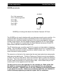
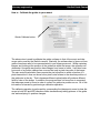
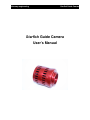
fishcamp engineering
Starfish Guide Camera
Starfish Guide Camera
User’s Manual
fishcamp engineering
Starfish Guide Camera
Table of Contents
Limited Warranty
4
Introduction
5
Installation
6
Hardware I/O Connectors
6
GUIDER port pinouts
7
Software Installation
8
Microsoft Windows Software Support
8
Mac OS X Software Support 9
StarLink Tutorials
10
Navigating the ‘StarLink Control’ Window
10
How to - Take a Picture with the Starfish Camera
12
How to - Adjust the Image Display
14
How to - Work with a sub-frame of the image sensor.
18
How to - Capture Calibration data for the image sensor
20
How to - Auto Calibrate Images
25
How to - Save images to Disk
27
How to - Operate the Camera’s TEC cooler
29
Operating as a Guide Camera
31
How to - Setup the camera for guiding
31
Hardware interface checks
31
How to - Setup ‘Guiding’ mode on the program
32
How to - Acquire a Guide Star
34
fishcamp engineering
Starfish Guide Camera
How to - Calibrate the guider to your mount
36
How to - Start Guiding
38
Reference - Guider Windows 39
Reference - Guiding -> Summary tab view
39
Reference - Guiding -> Guide Star Data tab view
41
Reference - Guiding -> Guide Star Error tab view
43
Reference - Guider -> Parameters tab view
44
Reference - Guider -> Images tab view
47
Reference - Guide History Window
48
Reference - Imaging Windows
Reference - Imaging -> Filter Wheel tab view
49
49
Troubleshooting
50
Autoguiding
50
fishcamp engineering
Starfish Guide Camera
Limited Warranty
The Starfish camera hardware is warranted to be free from defects in materials and workmanship for
a period of one year from date of shipment from fishcamp engineering. Defects caused by misuse,
abuse, or shipment are not covered.
Defective equipment that is subject to this limited warranty will be repaired or replaced at the option
of fishcamp engineering if we are notified during the warranty period. The customer must obtain a Return
Material Authorization (RMA) number before returning any equipment. Shipping costs from fishcamp
engineering will be paid by fishcamp engineering. Equipment should be packaged in the original shipping
container if possible, and the RMA number must be clearly marked on the outside of the package.
The information provided in this manual is believed to be correct, however fishcamp engineering
assumes no responsibility for errors contained within. The software programs are provided "as is" without
warranty of any kind, either expressed or implied.
No other warranty is expressed or implied. Fishcamp engineering shall not be liable or responsible
for any kind of damages, including direct, indirect, special, incidental, or consequential damages, arising
or resulting from its products, the use of its products, or the modification to its products. The warranty set
forth above is exclusive and in lieu of all others, oral or written, express or implied.
The information covered in this manual is subject to change without notice.
fishcamp engineering
Introduction
Starfish Guide Camera
fishcamp engineering
Starfish Guide Camera
Installation
Hardware I/O Connectors
GUIDER
Pin #1
Back of Starfish Camera showing I/O connectors
‘Guider’ connector - this connector is used to connect the Starfish camera to your
telescope mount so that it can control the mount movement. Guide corrections to the
mount are accomplished through this interface.
‘USB’ connector - this connector is used to connect the starfish camera to your computer. Power to operated the camera is also provided by the USB interface.
‘TEC PWR’ connector - this connector provides power for the TEC cooler in the camera. +12VDC with center pin positive.
‘RS-232’ connector - this is a standard serial data connector for interfacing with external devices such as filer wheels or motorized focusers.
Status LED’s - these indicators provide visual feedback on the camera’s operation.
The ‘status’ indicator will blink when the camera is communicating with the host computer. Each individual ‘direction’ indicator will blink to signify that the telescope mount is
being commanded to move in that particular direction.
fishcamp engineering
Starfish Guide Camera
GUIDER port pinouts
Pin 1: Not connected
Pin 2: Common (ground)
Pin 3: RA+
Pin 4: DEC+
Pin 5: DECPin 6: RA-
GUIDER
Pin #1
GUIDER port looking at the back of the Starfish Camera’s I/O Panel.
The GUIDER port is used to interface with your telescope mount’s motor controller. It is
via this interface that guide correction commands are sent to the telescope mount.
While there is no universal standard interface on the various manufacturer’s telescope
mounts for this function, the most popular interface standard is the ST-4 style guider
port. The ST-4 guide port is named after the Santa Barbara Instruments Group ST-4
guide camera that was manufactured years ago.
The ST-4 interface uses a modular style RJ-12 connector and jack similar to telephone
cabling. They are different however. Telephone cabling uses an RJ-11 connector which
is a six position connector but with only the four middle contacts used. The RJ-12 connector uses all six contact positions.
The connector on the back of the camera has the exact same pinouts as many popular
telescope mount guider ports. The Astro-Physics and Celestron mounts are examples
of these. As such, you will need a ‘one-to-one’ interface cable to connect the camera to
the mount. That is the cable must connect pin-1 to pin-1. Be careful since it is possible
to have a cable constructed as a ‘reverse’ pinout cable. These cables have pin- connected to pin-6 on the opposite end of the cable.
The key point to note is that signal pin-2 is the common pin. Make certain that
this signal is connected properly to the correct signal pin on your telescope
mount’s guide port. Otherwise you run the risk of damage to the Starfish camera
or your mount’s controller. If there is an uncertainty about this, don’t hesitate to
contact fishcamp engineering’s technical support staff for assistance.
fishcamp engineering
Starfish Guide Camera
Software Installation
Microsoft Windows Software Support
PC support for the Starfish camera comes with a Windows XT driver and camera plug-in
support for various image capture applications. Regardless of which image capture
program you use, you will need to install the Windows XP driver first.
There are four files associated with the Windows driver for the Starfish camera:
1. FCUSB.SYS - Windows driver
2. FCUSB.INF - Driver INF file
3. ‘gdr_usb.hex’ - this file is a firmware program that runs on the USB interface
processor in the Starfish camera. It is downloaded to the camera at startup time
from the host computer.
4. Guider_mono_revx_intel.srec - firmware program that executes on the image
processor in the Starfish camera. It is also downloaded to the camera from the
host computer at startup time.
All of these files are stored in the C:\Program Files\fishcamp install directory.
To install this driver, connect the Starfish camera to your PC. When Windows prompts
for a driver or indicates that it needs a driver, direct the PC to use the FCUSB.SYS
driver by steering it to the FCUSB.INF file.
fishcamp engineering
Starfish Guide Camera
Mac OS X Software Support
Insert the CD-ROM that came with the Starfish camera and double click the install program’s icon to start the installation procedure. Follow the on-screen instructions.
There are four files that will be installed on your computer by the installation:
1) ‘gdr_usb.hex’ - this file is a firmware program that runs on the USB interface
processor in the starfish camera. It is downloaded to the camera at startup time from
the host computer. This file is copied to the /Library/Application Support/fishcamp/ directory on your computer.
2) ‘Guider_mono_revx_intel.srec’, ‘Guider_mono_revx_ppc.srec’ - these files are
firmware programs that execute on the image processor in the starfish camera. It is
also downloaded to the camera from the host computer at startup time. The files are
copied to the /Library/Application Support/fishcamp/ directory on your computer. Only
one of these files are used depending upon which processor is in your Macintosh computer.
3) ‘Starlink’ - this file is the application software for the starfish camera that allows
you to operate the camera in order to take pictures or auto-guide. This file is copied to
the /Applications folder on your computer.
StarLink Application ICON.
fishcamp engineering
Starfish Guide Camera
StarLink Tutorials
Navigating the ‘StarLink Control’ Window
The StarLink application displays a main control window that allows the user to change
parameter settings and get status information from the camera being controlled. It is
helpful to the user to understand basic navigation within the control window.
The application is designed for three distinct modes of operation:
• controlling a camera to be used as the primary imager.
• controlling a camera to be used as an auto-guider.
• processing captured images.
Main Operation view tabs
Sub-operation view tabs
This is the window where you will control most of all the operations of the starfish camera. It has a set of tabbed views at the top of the window that correspond to the three
modes of operation. The following three modes are presently defined:
Operation Tabs:
• Guiding - tabbing to this view will allow you to operate the Starfish camera as a
telescope mount guide camera.
• Imaging - tabbing to this view will allow you to use the Starfish camera as a primary imaging camera.
• Processing - tabbing to this view will allow you to manipulate images you previously captured with the Starfish camera. This function is not yet implemented in
the current version of this program.
fishcamp engineering
Starfish Guide Camera
Sub-operation Tabs:
Below the ‘Operation Tabs’ are a set of ‘Sub-operation Tabs’. These allow you to bring
up views that display more detailed information applicable to the currently selected top
level view.
fishcamp engineering
Starfish Guide Camera
How to - Take a Picture with the Starfish Camera
1) Connect the Starfish camera to your computer via the supplied USB interface cable
2) Double click the ‘StarLink’ application icon to launch the camera’s control program.
3) The program will take a few seconds to establish communication with any cameras
plugged into the computer before opening up the application’s windows. While it is
searching for cameras, it will display status messages in the main control window. It will
then display the following window:
StarLink application main control window
fishcamp engineering
Starfish Guide Camera
4) Press the ‘Camera’ sub tab under the ‘Imaging’ main tab view.
Select a Camera
Then press ‘Connect’
5) Select a camera from the camera popup control and then hit ‘connect’. This defines
the camera that you will be using for subsequent operations.
6) Press the ‘Summary’ sub tab under the ‘Imaging’ main tab view.
7) Enter an appropriate time value in the ‘Exposure Time (secs.)’ txt field. This number
is any number from 0.001 to 300.0 (1ms to 5 Minutes) and sets up the exposure time for
any subsequent pictures taken with the camera.
8) Press the ‘Take Light Frame(s)’ button to start the exposure and upload the image
from the camera. The picture will be displayed in the image window.
Click this button to take a
picture.
Enter exposure time here.
9) You have successfully taken your first picture with the Starfish camera!
fishcamp engineering
Starfish Guide Camera
How to - Adjust the Image Display
The ‘Image Adjustment’ window has several controls that allow you to adjust the appearance of the images in the image
display windows. There are two sets of controls. One for
the Main Imaging Camera Window and the other for the
Guide Camera Window. You select which set of controls are
active via the tabs at the top of the Image Adjustment window.
The following controls are available in the Image Adjustment
window:
Median filter - when this box is checked, the program will
compute the median value for a group of neighboring pixels
and replace each pixel value with the median
Noise Reduction - Reduces noise using a threshold value
to define what’s noise. Small changes in luminance below
that value are considered noise and get a noise reduction
treatment by locally blurring. Changes above the threshold
value are considered edges, so they are sharpened.
Sharpness - increases the image detail by sharpening.
Gamma - Adjusts midtone brightness. This is a nonlinear adjustment that effectively
changes the slope of the transition between black and white.
Exposure - Adjusts the exposure setting for an image similar to the way you control exposure for a camera when you change the F-stop.
Contrast / Brightness - familiar image adjustment controls.
Invert - flips pixel mapping such that smaller pixel intensities are mapped to white and
larger values mapped to black
Any or all of these image adjustments can be applied to the image simultaneously.
Pressing the ‘Reset All’ button will put all of the controls back to their default values.
fishcamp engineering
Starfish Guide Camera
Another related topic to image adjustment is the histogram display that can be a useful
tool for determining the correct exposure setting when taking a picture. Getting most of
the pixel values in a wide range across the possible pixel values will help you get the
most information out of your image.
The ‘Imaging -> Display’ sub-operation tab view shows the histogram of the last captured image from the camera. This view is shown below.
The bottom of the window shows some statistical information about the RAW image
data of the current picture. In the center is the histogram graph. Since only the monochrome version of the Starfish camera is supported at this time, only a luminance graph
of the image is drawn.
There is a zoom slider on the right side of the graph that allows you to adjust the scale
of the Y-axis of the graph.
fishcamp engineering
Starfish Guide Camera
Drag mouse over histogram to show bin information.
Dragging the mouse across the histogram graph will display information cumulative to
all of the histogram bins selected. This can be helpful in determining features visible in
a particular image.
Since looking at the shape of the image histogram is so useful in determining the correct exposure setting for a picture, we have included a small thumbnail version in the
upper left hand corner of the image display window. This histogram auto-scales the Yaxis depending upon the nature of the histogram value counts.
fishcamp engineering
Starfish Guide Camera
There is one last tool that you can use to help understand the pixel intensity levels in
your captured images. In the image display window if you hold down the <option> key
while mousing around the image, the intensity of the pixel under the mouse will be displayed. An example of this is shown below. It is sometimes helpful to have the zoom
scale set pretty high when using this feature of the program.
Pixel intensity display attached to cursor.
fishcamp engineering
Starfish Guide Camera
How to - Work with a sub-frame of the image sensor.
The Starfish camera has a native resolution of 1280 x 1024 pixels. A single image from
the camera will have a total of 1.3 Mpixels. However, the camera can be operated in a
sub-frame mode where an arbitrary rectangular region of the image is captured by the
camera.
This can be useful when you are imaging a small object that does not take up the entire
field of view in the full frame mode. The advantage here is that the image file size is a
lot smaller thus saving disk space on your computer.
There is another advantage in that image capture and upload to the computer can be
much faster since a smaller number of pixels have to be transfered over the USB interface and handled by the computer. This is especially useful during auto-guiding with the
camera or focusing the camera. You can define a small sub-frame around a particular
star being used for focusing or guiding and then operate the camera in sub-frame mode.
Frame rates can be greater than 60 frames/sec for small sub-frames.
To select a sub-frame region of interest on the Starfish camera:
1) Make sure you have ‘Full Frame’ mode set in the image window. It is also
helpful to have the zoom scale set so that you can see the entire image.
2) Click the ‘Take Light’ button to take a picture with the camera. The image window will display the picture just taken.
3) Using the mouse, draw a rectangle around the desired region in the image
window. The region will be displayed with a yellow rectangle overlay on the
image.
4) Click the ‘Sub Frame’ button at the top of the image window. This will switch
the camera’s mode of operation.
5) Click the ‘Take Light’ button to take a picture. The image window will display
the picture just taken but the image will be smaller as defined by the region of
interest just entered.
fishcamp engineering
Starfish Guide Camera
Defining a sub-frame region in the image window.
Subsequent image capture.
fishcamp engineering
Starfish Guide Camera
How to - Capture Calibration data for the image sensor
Modern image sensors have astounding image quality over those of older designs.
However, astro-imaging places high demands on the sensor in terms of image quality
due to the fact that the objects being imaged have such low light intensity. There are
techniques that can be used to extract the best image information from a given picture
and this can have a dramatic effect on the resulting quality of the picture. The techniques rely primarily on reference images from the image sensor in order to correct for
various image noise sources.
The program can assist in creating three different reference images from the camera for
use in calibrating the final image. These reference images are called ‘bias’, ‘dark’, and
‘flat-field’ images.
‘Bias’ frames are images taken at the absolute fastest exposure setting of the camera
and will record the basic noise floor of the image sensor. They can be used to correct
for fixed differences in levels across the entire frame of an image. The level differences
are inherent in the image sensor and not related to the actual light falling on the sensor.
‘Dark’ frames are images that capture the build up of something called dark current in
the image sensor. Just like Bias frame pixel offsets, the pixel intensity due to dark current is not related to the actual amount of light falling on the sensor. Dark frames are
taken with the lens cap covering the camera so that no light is falling on the sensor during the exposure. That is why they are called ‘Dark Frames’. Dark current builds up
over the duration of an exposure being taken by the camera. Long duration exposures
will accumulate more dark current in the pixel wells than a picture taken with a shorter
exposure setting. Because of this time dependancy in the dark current captured by an
exposure, dark frames are always taken with the same exposure setting as is used for
the actual picture of interest. Of note, is that an image sensor’s dark current specification is lower when the operating temperature of the chip is colder. In general, the dark
current gets halved for each ~7C drop in temperature of the chip. That is why the Starfish camera has a TEC cooler built into its design. Turning on the cooler in the camera
will reduce the dark current noise in your images by a significant amount. To see how
much, you can compare the image histograms of two images. Each taken at a different
temperature.
The following pictures, and accompanying histograms, illustrate the effect of cooling the
image sensor. The two dark frames were each taken with a 60 second exposure time
on the Starfish camera. The one on the left was taken, without the TEC cooler turned
on, at 25 degrees C. The one on the right was taken with the image sensor cooled to
10 degrees C.
fishcamp engineering
Starfish Guide Camera
60 seconds @ 25C 60 seconds @ 10C
60 seconds @ 25C 60 seconds @ 10C
Dark frames taken at different temperature settings.
‘Flat’ frames are images taken with an even amount of illumination across the image
sensor. One way of achieving this is by placing a T-shirt over the objective of your telescope while taking a picture of the twilight sky. Make sure that the exposure setting is
such that the average pixel intensity of the resulting image is somewhere around 33% of
maximum as shown by the histogram display. Flat frames will record the intensity variation of the pixels across the frame of the entire imaging system. This includes the optical system as well as that of the camera itself.
Once the three calibration reference frames are acquired, they can be used to adjust
any subsequent pictures taken with the camera such that the resulting image shows
only light intensity variations due only to actual photons falling on the image sensor.
The image will not have any noise associated with the various noise sources described
above.
fishcamp engineering
Starfish Guide Camera
10 Second exposure (magnified) before Dark Frame subtraction example.
10 Second exposure (magnified) after Dark Frame subtraction example.
On thing to note is that there will be some time-dependent variation in the calibration
frames from random electrical noise sources within the camera. This is due to some
basic physical properties associated with the image sensor itself. This characteristic is
not unique to the design of the Starfish camera but is something that all astro-cameras
fishcamp engineering
Starfish Guide Camera
will exhibit. To circumvent this, you will usually take several different images of each
type of calibration frame and average or median combine them together before using
them. A good rule of thumb is to take at least 5 of each calibration frame.
To capture the calibration frames for the Starfish camera:
1) Setup the camera for the image resolution you will use for the final picture.
Changing from full-frame to sub-frame mode or changing the size of the subframe will invalidate the calibration frames.
2) Go to the ‘Imaging -> Calibration’ tab.
3) Cover the camera lens prior to taking either the Bias or Dark calibration
frames.
4) Take a Bias calibration frame by specifying the number of bias frames to take
and then pressing the ‘Take Bias’ button. The specified number of Bias frames
will be taken and then median combined into a Master Bias frame that will be
used for all subsequent image calibration operations.
5) Take a Dark calibration frame by specifying the number of dark frames to take
and entering the exposure duration to use. Make sure to enter the same exposure time that will be used to take the actual images. Complete the operation by pressing the ‘Take Dark’ button. The specified number of Dark frames
will be taken and then median combined into a Master Dark frame that will be
used for all subsequent image calibration operations. Since most astrophotography picture are taken with long exposure times, this operation can
fishcamp engineering
Starfish Guide Camera
take a very long time. For instance, if the exposure setting is set to 180 seconds, and you are going to average 8 dark frames, it will take 24 minutes to
take all of the required dark frames. Dark frames should also be taken with
the image sensor at the same temperature that the final picture will be taken
with. If using the TEC cooler on the camera, let the sensor stabilize at its final
temperature setting before taking the Dark frames.
6) Setup for the flat frame exposures by evenly illuminating the image sensor on
the camera and selecting an appropriate exposure setting. It is best to select
an exposure time that puts most of the pixels in the histogram graph at the 1/3
point between black and white.
7) Enter the number of frames to average for the Master Flat Frame and then
press the ‘Take Flat’ button.
10) Optionally save any of the calibration frames to your disk.
When all of the calibration frames have been collected, you can begin taking the actual
images.
fishcamp engineering
Starfish Guide Camera
How to - Auto Calibrate Images
After you have acquired calibration frames for the camera’s picture taking session, you
can use them to calibrate the images you take with the camera. The calibration frames
are used in the following sequence:
1) Subtract the Master Bias Frame from the camera’s RAW image.
2) Subtract the Master Dark Frame from the image generated in step #1
3) Divide the image generated in step #2 by the Master Flat Frame.
Since you can just save any of the RAW image frames taken by the Starfish camera to
disk, you could just do the above image calibration using other third party image processing applications. There are several good programs to chose from including programs dedicated to Astro-photography as well as general purpose image processing
applications like Photoshop.
An easier way to do this is to let the StarLink program do it automatically for you as it
captures images from the camera. This is called ‘On-the-fly Calibration’.
The tab view ‘Imaging->Summary’ has several controls that allow control over the
automatic image calibration features of the program. There are four check boxes presented to the user. The first three are associated with the three types of calibration reference frames and allow you to select whether or not to apply that particular calibration
operation.
Auto-calibrate controls.
fishcamp engineering
Starfish Guide Camera
The fourth check box allow you to perform a bad pixel removal operation on the image.
Even after calibrating the image with the calibration reference frames, the image may
have several hot or cold pixels. These are usually associated with defects in the image
sensor and are at a fixed position relative to the pixel array in the sensor. Checking the
‘Bad-pixel Removal’ box will allow the program to find, and map out all of these bad pixels in the image.
You may notice that in the above screen snapshot, one of the check boxes are shown
disabled. The program checks to see that a valid calibration frame has been acquired
by the camera before allowing you to specify the operation to be performed. If, for instance, you have not collected a flat frame, the ‘Flat Field’ check box will be disabled
and the red warning text will be displayed reminding you to perform the Flat Frame acquisition.
Changing the mode of the camera from Full-frame to Sub-frame operation, or changing
the size of the sub-frame region will invalidate the calibration frame data and you will
have to take them over again.
You can see the effects of applying a various calibration operation by checking and unchecking the respective check box. The operation will be alternatively done and undone with the image redisplayed each time.
fishcamp engineering
Starfish Guide Camera
How to - Save images to Disk
You will usually want to save any captured pictures to your hard disk for later postprocessing and viewing. The following controls allow you to save images to disk:
Controls to allow saving images to disk
Two kinds of image files can be generated by the program. The first is the RAW camera
image as captured by the camera. No image manipulation operations will be performed
on the image. It will be saved as is.
The second image type that can be saved is an auto-calibrated image. This kind of image is a version of the camera RAW image with the calibration frames applied. Only the
calibration operations specified by the check boxes in the ‘Imaging -> Summary’ view
will be applied.
You can specify either, or both image file types to be generated by the program. Any
images stored, will be TIFF file types. Images are saved right after being downloaded
from the camera.
Pressing the ‘Set Save Folder’ button will allow you to specify where the images will be
stored. You can specify a directory location as well as a file name prefix that will be
used to name the image files. The program will automatically append a file name suffix
to the image file names.
fishcamp engineering
Starfish Guide Camera
The following naming convention is used by the program to name the image files when
they are saved:
<prefix>_RAWlight_#.tiff
<prefix>_CALlight_#.tiff
So, for example, if you specify a file name prefix of “M51” and capture two pictures with
the camera, the following image files are saved:
M51_RAWlight_0.tiff
M51_CALlight_0.tiff
M51_RAWlight_1.tiff
M51_CALlight_1.tiff
fishcamp engineering
Starfish Guide Camera
How to - Operate the Camera’s TEC cooler
The Starfish camera can be operated with the internal TEC cooler optionally enabled.
You do not need to turn on the cooler, nor have its power cable attached, in order to
take pictures with the camera. This is true for imaging sessions where the camera is
used for short exposure settings like planetary imaging or operation as a guide camera.
You would, however, want to turn the cooler on when imaging deep space objects that
require long exposure durations. This is because with long exposures, the dark noise
will be a significant noise source in the final images. It is recommended that the cooler
be used for any exposures longer than about 15 seconds.
The following controls are associated with the camera’s internal cooler:
TEC Cooler controls
To use the TEC cooler, you will need to provide a +12VDC power source. The camera
comes with both an AC power supply and a battery cable for use with a user supplied
battery. A standard, auto style cigarette light plug is used on the battery cable.
If the camera does not detect that the external power cable is attached to the camera, it
will display a warning message and not allow you to turn on the TEC cooler.
fishcamp engineering
Starfish Guide Camera
Two controls are provided. The ‘TEC Enable’ check box allows you to turn on and off
the cooler. The ‘Set Temperature’ number field allow you to set the target temperature
of the cooler.
The starfish camera can cool to a minimum of -12C below the ambient temperature. You
can get an idea of what the ambient temperature is by looking at the ‘Current Temperature’ reading before turning on the TEC cooler. The camera has a built in thermistor for
measuring the image sensor’s temperature. It uses this to regulate the cooler’s temperature. The program displays the temperature measurement reading with an update
approximately every 5 seconds.
So, for example, if the ambient temperature of the camera is 20°C, you could easily cool
to 8°C by entering an 8 in the ‘Set Temperature’ number field and checking the TEC enable check box.
Along with the current temperature reading, the program will display the current power
level set by the cooler controller.
The TEC cooler in the camera will generate a lot of heat when operating. This heat is
dissipated by the camera’s internal fan when operating. This design works fine up to a
point since at high power settings to the cooler, more heat will be generated than can
easily be dissipated by the heat sink and fan. It is recommended that you chose a temperature setting that results in a power level setting of 75% or lower so that there is
plenty of headroom for the cooler regulator to operate.
fishcamp engineering
Starfish Guide Camera
Operating as a Guide Camera
How to - Setup the camera for guiding
Hardware interface checks
The Starfish camera was designed to be used primarily as a guide camera for your telescope mount. It does this by taking a picture of a star at regular intervals and determining if your mount is tracking the star accurately enough. If it detects a mount tracking
error, it will command your telescope mount to make a pointing correction in order to
keep the reference star at a fixed position.
Manual Slew controls. You will need to attach the Starfish ‘GUIDER’ port to the guide port on your telescope mount. See the hardware installation section of this manual for more information.
Verify that the starfish camera is properly interfaced to your mount. Open the camera control application and click on the ‘Telescope Control’ window.
Press one of the manual slew control buttons in the
window and, if everything is OK, the telescope mount
will slew in the desired direction. Press each of the slew buttons to make certain that the telescope responds to commands in each of the four directions.
You will also see a visual indication of mount control
via the status LEDs on the back of the camera.
fishcamp engineering
Starfish Guide Camera
How to - Setup ‘Guiding’ mode on the program
In the Starlink Control window, click the ‘Guiding’ operation tab. This puts the program
into the mode used to operate the Starfish as a guide camera. The ‘Guiding’ and ‘Imaging’ modes of the control program can be used together but a given camera can be assigned as either your primary imaging camera or your guide camera. It can not do both.
This means that you would have to have two cameras to perform both imaging and
guiding.
‘Guiding Tab’
Before you can begin guiding you will have to specify the camera to use under the
Guiding->Camera sub view tab.
Select your guide camera in this view.
fishcamp engineering
Starfish Guide Camera
While in ‘Guiding’ mode, the program will continuously take pictures with the camera.
The exposure time and seconds between pictures can be set in the ‘Camera’ suboperation tab view and determine the repetition rate that the pictures will be taken.
fishcamp engineering
Starfish Guide Camera
How to - Acquire a Guide Star
When in guide mode of the program the first thing that needs to be done is to get the
camera taking a picture of the desired guide star and setting up to compute it’s location.
This should be done in full-frame mode so that you can get the widest possible field of
view with which to select the guide star. Aim you telescope at a suitable guide star and
focus the camera. Make sure you are in the guide mode of operation with the program.
Your image display window will look something like this:
Guide Star location cursor
Guide Star region Mask
This image is being displayed in sub-frame mode for the sake of clarity. You should be
operating in full-frame mode.
There are two items to note. The purple rectangle overlay on the image is a region that
you will define. This region is used to tell the program where to examine the image for
calculating a guide star position. You should select a suitable guide star to draw this region around. Note that when in guide mode you will need to press the <control> key
and then drag your mouse around the region of interest in order to define this mask.
The red cursor will always be drawn somewhere within the purple region mask rectangle. It graphically shows the calculated position of the guide star so will usually by sitting directly on top of the star. The program uses a centroid calculation algorithm to calculate the star’s position. The algorithm can be fooled in circumstances where there is
more than one bright object within the mask region. For example, if there are two stars
within the region, the program may think that the guide star is located midway between
the two. The remedy is to draw a smaller region mask around the guide star you intend
to use.
fishcamp engineering
Starfish Guide Camera
The ‘Guiding -> Guide Star Data’ view will show more information about the nature of
the imaged guide star. Of particular note in this view is the ‘Pixel Intensity Threshold’
slider. This slide selects the threshold level of intensity that the program assumes is
part of the guide star. A higher level setting will be useful in cases where there is a high
background noise level in the captured image. A setting of somewhere around 75% is
recommended.
Threshold slider
fishcamp engineering
Starfish Guide Camera
How to - Calibrate the guider to your mount
Guider Calibrate button
The above view is used to calibrate the guider software to that of the mount and telescope optics used by the Starfish camera. Basically, the software has to figure out how
guide corrections need to be communicated to your telescope mount. When capturing
images and looking at the position of the guide star within the image, the software can
determine if the guide star position has changes from frame to frame. It will also know
how much of a position change has occurred but only in pixel size units of the image.
The star centroid calculation can compute the star’s position to within a fraction of a
pixel element but it does not know how a pixel’s size relates to the absolute position of
the guide star in the sky. That is because different optical paths will produce different
fields of view of the image. In addition, the program does not know how to command
the telescope mount to move in order to correct for guide star position errors. All of this
information is learned by performing a calibration operation.
The calibrate operation is performed by commanding the telescope’s mount to slew the
scope in both N/S and W/E directions while simultaneously taking pictures of the guide
star and analyzing it’s position changes.
fishcamp engineering
Starfish Guide Camera
To perform a calibration, perform the following steps:
1) Center a guide star in the image window and define a very large region mask
around the guide star. The large mask is necessary since the program will be
telling the telescope to slew a potentially large distance.
2) Define the ‘calibrate backlash pixels’ and ‘seconds’ fields. Your mount will
have some backlash in its drive train and this is how we compensate for that.
The ‘pixels’ field defines the distance the guide star position must change before the program decides it has taken up all of the backlash in the system.
The ‘seconds’ parameter tells the program how long to slew the scope before
deciding that the backlash is taken up. Both of these conditions must be met
for the program to decide that the backlash is taken up.
3) Define the ‘calibrate movement pixels’ and ‘seconds’ parameters. This tells
the program how long to slew in a particular direction while characterizing the
mount’s movements. So for example, a longer slew time will be needed for
telescope mounts that will be guiding at a very slow rate. Fast guide rates will
need a shorter time to be entered.
4) Setup the telescope’s mount controller for the desired slew speed you will be
using to guide.
5) Press the ‘Calibrate’ button. The program will begin to slew the telescope in
both the NORTH and then WEST directions in order to determine how the
mount moves relative to the commands being given it. The result is to fill in
the ‘NORTH Slew Counts/sec’ and ‘WEST Slew Counts/sec’ number fields. At
the end of the calibration sequence, these fields will display the displacement
in guide star position (pixels) for a one second slew command. A bigger number will represent a mount with a faster slew speed or a long optical focal
length lens in front of the camera. A negative number signifies a reversal in
direction.
fishcamp engineering
Starfish Guide Camera
How to - Start Guiding
After the system is setup as described above you can start guiding by simply checking
the ‘Auto-Guide Enable’ check box. The system will start tracking the guide star at that
point and present a log and graph of guide performance in the ‘Guide History’ window.
fishcamp engineering
Starfish Guide Camera
Reference - Guider Windows
Reference - Guiding -> Summary tab view
This view presents the user with only the most important information relating to the operation of the guide camera. As such, the information is a duplicate of the same information presented in some of the other tab views of the window. A screen dump of this
view is shown below:
The following controls and fields are presented in this view:
Auto Guide Enable check box - this control allows the user to turn on/off the guide
corrections to the mount. Only when this check box is checked will guide corrections be
sent to the telescope mount. You should have previously calibrated the auto-guider before enabling this check box.
fishcamp engineering
Starfish Guide Camera
Predictive Guide Enable check box - this control enables the use of the predictive
guide enable feature of the program. Initially after starting auto-guiding, the program
simply relies on the information garnered from the picture of the guide star to calculate
the guide corrections. After a reasonable time period (~1 minute) of guiding, the program can determine from the guide history the nature of the corrections being sent to
the mount. It uses this to pro-actively generate guide corrections to the mount without
having to wait for a new guide star image to be acquired. The result is that smaller but
more frequent guide corrections are sent to the mount. This can sometimes, dramatically, improve the guiding of a given run. Un-checking this box will cause the program
to only rely on guide star images for calculating any corrections to be sent to the mount.
Auto-guider State status - this line will display the current running status of the autoguider.
Guide Star Error status - these values represent the RA and DEC errors calculated by
subtracting the current guide star position of the last picture and the target guide star
position.
Camera Exposure Time (seconds) - you may define an exposure time that is used for
all subsequent pictures taken by the guide camera. This value can be a minimum of
0.001 second up to a reasonable value of perhaps a couple of seconds. The increment
is 0.001 seconds.
Guider Aggressiveness sliders - these controls allow you to specify how guide calculations are computed. After every guide star picture is taken, the program computes the
ideal mount correction that would need to get sent to the mount to totally correct all of
the detected guide star position error. This ideal value is then modified by the setting of
the Guider Aggressiveness sliders before being sent to the mount. So for instance, if
the ideal mount correction value is a pulse of 100ms, and the Guider Aggressiveness
slider is set to 50%, then the final guide correction sent to the mount will be 50ms. The
slider value can be set anywhere between 50% and 150%. In general, a higher value
setting of this slider will result in tighter guiding. A too high of a value will tend to make
the system unstable since the system will tend to over-correct for any detected errors in
position. The best setting to use depends upon many system factors such as mount
and optics characteristics of your system. It is recommended that you start out with a
smaller value and then try increasing the value until the desired guiding performance is
achieved.
There are independent sliders to allow for different settings on RA and DEC of your
mount.
fishcamp engineering
Starfish Guide Camera
Reference - Guiding -> Guide Star Data tab view
This view shows the results of the guide star position calculations by the program. The
program uses a centroid calculation algorithm with an aperture mask within the guider
camera picture. The Guide Star Region Mask is a rectangular region within which the
program searches for the guide star centroid. The mask is used in order to keep the
algorithm from getting confused when more than one bright star is captured in the images by the guide camera. Normally, you would define this region by drawing a box
around the guide star while holding down the <control> key in the Guide Camera Image
Window. You can however, manually enter the coordinates of the rectangle’s corner
points in this view.
Guide Star Data view
Guide Star (raw) - result of the centroid calculation from the last image taken by the
guide camera.
fishcamp engineering
Starfish Guide Camera
Sky Intensity average - the calculated luminosity of the background sky surrounding
the guide star. This value is subtracted from every pixel intensity value within the guide
star region mask area before using the pixels values to calculate the centroid.
Star intensity threshold - this value is the threshold intensity level that the program
uses to decide whether a given pixel is part of the sky background or part of the pixels
belonging to the guide star. This threshold is set to a point somewhere between the sky
intensity level and the max pixel intensity detected in the pixels under the guide star.
Changing the setting of the ‘Pixel intensity threshold’ slider will allow you to change this
threshold. Too close to the bottom and you will get poor calculation results in images
that have high noise in the background sky pixels. Too high, and the calculation will
lose precision.
Max Pixel Intensity - this value is the pixel intensity level of the brightest pixels under
the guide star.
Num significant Pixels - the total number of pixels that are above the ‘Star intensity
threshold’ level. This number should be at least a dozen or so pixels for a good guide
star position calculation. If too low, then a lower setting on the ‘Pixel intensity threshold’
slider or a longer integration time should be set.
Pixel intensity threshold slider - this control allows you to set the ‘Star intensity
threshold’ parameter.
# readings to average - this parameter allows you to define how many readings are
averaged to obtain the guide star position calculation. Normally, this is set to ‘1’ and the
position calculation is based only upon the last image taken by the guide camera. In
certain situations, such as during poor seeing conditions, you might want to average two
or more readings before using the guide star position calculation.
Guide star average - the result of averaging ‘# readings to average’ in guide star position. These values should be the same as ‘Guide Star (raw)’ when only one image is
being averaged.
fishcamp engineering
Starfish Guide Camera
Reference - Guiding -> Guide Star Error tab view
This view presents the user with detailed information about the guide star position errors. A screen dump of this widow is shown below.
Guide Star Error view
The target position as well as the current guide star error from that target position is
shown. This is calculated from the last image taken from the guide camera.
Also shown is the first and second derivative of the guide star position. These correspond to the drift speed and drift acceleration status boxes in the view.
The Guide Star RMS error is calculated over the previous 100 samples of the guide star
position.
fishcamp engineering
Starfish Guide Camera
Reference - Guider -> Parameters tab view
This view presents some of the most important information related to the guider performance. A screen dump of this view is shown below.
Guider Parameters View
Calibrate button - pressing this button will start the guider calibration procedure. The
button will change to an ‘Abort’ button that you can press to cancel the procedure. During the calibration operation the telescope will be commanded to slew in both the
NORTH and WEST directions in order to characterize the response of the telescope
system to guide correction commands that are sent from the guider. Pressing the
‘Abort’ button will stop sending any slewing commands to the telescope mount.
Auto Guide Enable - checking this box will start the operation of calculating guide star
position errors and sending resulting error corrections to the mount. No guide corrections are sent unless this control is checked.
fishcamp engineering
Starfish Guide Camera
Predictive Guide Enable - checking this box will allow the program to use historical
guide correction data when calculating guide corrections to be sent to the mount.
Calibrate Backlash Pixels/Seconds - The calibration routine will attempt to take out
any gear backlash in the telescope mount during the calibration procedure. To do so it
will command a slew and wait a minimum amount of time and detected movement of
the guide star before deciding that all of the gear backlash has been taken out. These
text fields are where you enter the time and movement (in pixels) parameters. Both
have to be true in order to succeed in taking out the backlash.
Calibrate Movement Pixels/Seconds - the calibration routine will perform a slew of the
telescope mount in both the NORTH and WEST directions to characterize how the
mount responds to slew commands. While slewing, the program will slew for a minimum amount of time and minimum position change distance of the guide star. These
parameter fields are where you enter these parameters. When slewing, the program
will slew this amount of time and distance before stopping and calculating the results.
Auto-guider State - the guider algorithm of the program is implemented as a state machine internally. There are many states that the program will progress through while
calibrating and guiding. Several of these states are error conditions and will be displayed in RED. The current state of the state machine is always displayed in this text
field.
NORTH Slew Counts/sec - during the calibrate routine, the number of pixels of position
change per second observed of the guide star while slewing in the NORTH direction is
reported here.
WEST Slew Counts/sec - during the calibrate routine, the number of pixels of position
change per second observed of the guide star while slewing in the WEST direction is
reported here.
Calculated Camera Angle - After the calibrate routine has completed, the program will
calculate the angle of the guide camera relative to the main axis of the telescope mount.
The results measured and displayed in the NORTH Slew Counts/sec and WEST Slew
Counts/sec are used for this calculation.
seconds to wait after correction - some mount controllers cannot accept guider corrections at a very rapid pace. The Starlink program allows you to enter a delay parameter that will be inserted between successive guide corrections. This is where you enter
this parameter.
seconds / correction - This field allows you to specify how long each guide correction
will take. After sending a guide correction to the mount, the system will need to wait for
the mount to complete the correction slew before making another correction. This field
specifies this time. Since you cannot make a guide correction without first seeing the
results of the previous correction, the program will only make a guide correction after a
fishcamp engineering
Starfish Guide Camera
new picture is taken. The integration time currently set for the camera will therefore
take precedence to this parameter if it is longer.
Minimum move - guide corrections are not sent to the mount unless they are at least
big enough to exceed the value entered here.
Maximum move - guide corrections larger than this are never sent to the mount.
fishcamp engineering
Starfish Guide Camera
Reference - Guider -> Images tab view
The guide camera is continually taking pictures of the guide star region to make guide
star position measurements. Normally, these images are thrown out after the position
calculation is made.
In some cases, it would be preferable to save an image to disk instead of throwing it
away. An example would be where you wanted an image log of guider performance or
time lapse image sequences.
This view allows you to specify the timing of the images to save. To enable the save
operation, you need to check the ‘Save Guider Images to Disk’ check box and specify a
frequency of the images that will be stored. Intermediate images that are captured are
not stored. Only images captured after the ‘Frequency of Save’ timer has expired are
saved. Each time an image is saved, the time is restarted.
The ‘Set Save Folder’ button allows you to specify a filename and the location where
the images are stored.
fishcamp engineering
Starfish Guide Camera
Reference - Guide History Window
As long as a guider camera is connected, the history of the guider’s operations will be
logged in the ‘Guide History’ window. A screen shot of this window is shown below:
Guide History Window
The guide history is show in both a graphical and a tabular view. The graphical view will
present a strip-chart style graph of the RA and DEC errors as they occur over time. The
RMS error in the two axis can also be graphed. Each of these four values are assigned
a different color for the graph and the legend is displayed in the upper right hand corner
of the window.
There are two sets of controls in the window that affect the view of the graphical data.
The first is a set of check boxes that allow the user to specify which of the four parameters are graphed. Any or all of them can be shown by checking or un-checking their respective check box. The second control that is available to the user is the ‘zoom’ slider
that allows you to specify the size of the displayed graph.
Below the graphical display of the history data is a spreadsheet type display of the history data. More information is presented in the tabular view. Specifically, guide corrections that are sent to the mount are also logged along with the guide star position data.
fishcamp engineering
Starfish Guide Camera
Reference - Imaging Windows
Reference - Imaging -> Filter Wheel tab view
The StarLink program has built in support for the Fliger Lakes Instrumentation line of
filter wheels. The program will search for any filter wheels attached to the computer
upon startup. If a supported wheel is found, the following tab view will be displayed.
For each filter position, you can enter a text string describing the characteristics of the
filter installed. The descriptions entered will be saved in a user preferences file for the
program.
Basic filter selection is accomplished by selecting the desired filter position and then
pressing the ‘Set Wheel Filter Position’ button.
fishcamp engineering
Starfish Guide Camera
Troubleshooting
Autoguiding
An f/5 scope should be plenty fast enough to get a lot of bright guide stars. In practice,
with a one second exposure, you should be able to guide on mag 11 stars. First try
guiding on a very bright guide star and see how your guide performance is. If you are
able to guide well on a bright star but not dimmer stars, let's assume that your problem
is the guide star data. In the 'Guide Star Data' tab view there is presented a lot of data
on what the camera sees as the guide star. The key parameter is the 'Num significant
Pixels' field. After all of the centroid calculations are done and the threshold is applied,
this field will show the number of image pixels used that were significant. Everything
else was thrown away. You can play with the threshold setting in the view. It defaults to
33%. The 'num significant pixels' value should be >10 in my experience for good
guiding. If it is too small, then you can change the threshold or lengthen the camera
exposure to bump it up a bit. You can also turn up the gain on the image sensor output
amplifier.
The next thing is seeing conditions. This should only happen at short exposures. Anything less than a couple of seconds. However, if you have a short exposure and the
seeing is bad, then you can use the software's ability to average several readings before using the guide star position. That is under the '# of readings to average' field.
Next I would turn on guiding but turn OFF guide corrections to see the guide star drift
graph in the 'Guide history' window. Without guide corrections you will see immediate
drift depending upon the quality of your mount and the accuracy of your polar
alignment. The thing to look for is the smoothness of the drift. Drift in the DEC or 'Y'
direction in the graph should be a smooth, straight line. If not, then it is most likely that
the software is having a hard time getting a good guide star position. Or, bad seeing
conditions. The drift in RA or the 'X' direction will show some irregularities due to the
periodic error in your drive mount.
Next time you are out perform the test and see how it goes. We first need to ascertain
whether or not the guide star is the problem before moving on. If the system cannot get
a good guide star position calculation, then it won't be able to make good corrections
when the guiding is enabled.
One more thing, there is another possibility for guide star position errors. That is noise
in the image. This will happen under very faint guide stars and when you have the gain
turned way up on the image sensor output amplifier. You will be operating at the limits
of the image sensor at this point and the only thing you can do to help is to have the
program automatically apply a dark frame correction to the images before they are
used.