1
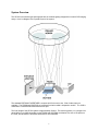
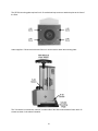
SE 200 Spectrograph
for use with
Andor Technology Cameras
Catalina Scientific Instruments
1870 West Prince Road #21
Tucson, Az 85705 USA
Phone: 520/571-8000
Fax: 520/571-0120
Web: www.catalinasci.com
System Overview
The SE 200 is an echelle-type spectrograph with an echelette grating designed for use with CCD imaging
arrays. Here is a diagram of the optical layout of the system:
The standard ENTRANCE APERTURE is a square slit 25 microns in size. Slits of other sizes are
available. The PRISM and GRATING are contained in what is called a “dispersion module”. The CCD is
contained in a camera head mounted at the exit port.
The focal length of the SE 200 system is approximately 200mm. The resolving power (λ/∆λ) ranges from
about 2000 to over 6000 depending on the PRISM and GRATING combination, the size of the pixels on
the CCD, and whether the camera is intensified or non-intensified.
1
Input Accessories
A pen lamp and filters can be used on the standard accessory mount. There
are two options for using a fiber as input: 1) A fiber holder with an X – Y stage,
or 2) An SMA connector
Dispersion Modules
The PRISM and GRATING reside in a cylindrical module that can be changed
by the user to provide different dispersion characteristics.
Fine Focus
The position of the PRIMARY MIRROR can be adjusted to focus the images on
the CCD detector.
CCD Cameras
The camera head is mounted at the exit port. For cameras without shuttering
capability, a shutter assembly can be added behind the ENTRANCE
APERTURE on the inside of the spectrograph. The shutter control box is
mounted above the camera head.
Shutter Control
For cameras without shuttering capability, a shutter assembly can be added
behind the ENTRANCE APERTURE on the inside of the spectrograph. The
shutter control box, mounted above the camera head, has a BNC connector for
TTL signals that control the opening and closing of the shutter.
KestrelSpec Software
Every SE 200 system comes with KestrelSpec™ software to acquire images
from the camera, focus and align the images, and calibrate and analyze the
spectral data. The first three sections of the KestrelSpec user manual explain
how to use the software. Start with the tutorial in Learning KestrelSpec. Go on
to Using KestrelSpec so the system can be configured, focused, aligned and
calibrated. Use the Reference section to learn about additional features for
analyzing data, identifying elements, and displaying and saving data.
2
Input Accessories
The SE 200 comes with a standard accessory holder for a pen lamp and a filter. The pen lamp holder is
mounted horizontally and a lamp can be inserted from either side. One side is 10mm and the other side
is 11mm in diameter to accommodate two different sizes of lamps. The filter holder is a plate with two
mounting screws. The bottom of the plate has a lip for holding the filter in place. The filters can be up to
2” x 2”, or 50mm x 50mm, in size.
There are 2 options for using an optical fiber as input:
1) An X – Y Stage: When using a stage, the filter holder must be removed so the X-Y stage holding the
fiber can be mounted. A fiber is inserted through the center of the X-Y stage until it is resting against the
ENTRANCE APERTURE. A tightening screw is used to hold the fiber in place. Keep in mind that one of
the X-Y adjustment screws is just above the tightening screw. It is easy to confuse the two of them.
The X – Y stage is used to center the end of the fiber on the entrance slit. See “Aligning a Fiber Using
the X-Y Stage” at the end of this manual.
3
2) An SMA Connector: An SMA connector can be used right at the ENTRANCE APERTURE so the
fiber can be attached directly to the connector. Using an SMA connector is much simpler than an X-Y
stage because the SMA comes pre-aligned to the entrance aperture.
SMA Mount and its Connector
Fiber attached to the SMA Connector
4
The SE 200 comes with a standard ENTRANCE APERTURE that is a 25 micron square slit. There are
additional slits available in various sizes, such as 10 x 50 microns, 25 x 50 microns, 50 x 50 microns, 75 x
100 microns, or any other sizes that may be required. Each slit is mounted at the ENTRANCE
APERTURE with 4 bolts. The slit dimensions are stamped on the mounting plate.
To change slits, there are two methods depending upon whether an SMA connector comes with each slit,
or an X-Y stage is being used.
1) When using an SMA connector, each slit mounting plate comes with the SMA mount already attached
and aligned with the slit. Do NOT remove the SMA mount from the slit. Keep the two pieces
together.
Mounting plate for
the slit with an SMA
mount already
aligned with the slit.
Keep the SMA and
slit mounts together.
The slit dimensions
are stamped on the
mounting plate.
2) When using an X-Y stage, remove the Input Accessory Holder and the X-Y stage if they are currently
mounted on the spectrograph.
Whether there is an SMA attached to the slit or not, the slit mounting plate can be removed by undoing
the 4 bolts holding the slit in place. All SE 200 slits come in the same-sized square mounting plate.
5
The direction of the grating dispersion is vertical at the ENTRANCE APERTURE. Keep this in mind when
a rectangular slit is being mounted. A rectangular slit, such as the 75 x 100 micron slit, can be mounted
two different ways depending upon whether the height of the spectral orders should be 75 microns or 100
microns tall. The dimensions of the rectangular and square slits are stamped on their mounting plates.
When an optical fiber is used with an X-Y stage, the stage is used to line up the fiber with the slit. The XY stage and its fiber holder are mounted directly onto the slit.
6
Once the X-Y stage is in place, remount the standard Input Accessory Holder and insert the fiber into the
fiber holder on the X-Y stage. This way, you can switch between using a pen lamp or a fiber as input to
the spectrograph. For details on aligning the fiber with the slit using the X-Y stage, see “Aligning a Fiber
Using the X-Y Stage” on the last two pages of this document.
7
Dispersion Modules
There are currently three standard dispersion modules: SE 200 Standard, SE 200 High Order and SE
200 UV modules. All modules cover a wavelength range of about 190nm to 1100nm. The High Order
and UV modules have higher resolution but their orders are closer together. When orders are close
together, there may be crosstalk between adjacent orders with either the High Order or UV module above
500nm, especially when analyzing a continuum spectrum. The UV module will have gaps in the data
above 500 or 600nm, depending upon the size of the CCD.
To change modules, remove the four Allen head screws around the outside of the module with the
wrench that has been provided. Do NOT touch the center bolt. Loosening this center bolt will change the
tilt of the PRISM and GRATING and cause serious misalignment of the system.
After the four outside screws have been removed, gently pull the module out of the SE 200. Always store
the module in a dust-free, cushioned bag. Another dispersion module can now be inserted. Push the
new module all the way in, making sure the flat edge is towards the camera and the four outside screws
line up with their holes. Tighten the four screws to secure the module in place.
After changing modules, be sure to update “Model Name” and the configuration parameters in the
Setup:Spectrograph Configuration… menu option of the KestrelSpec software. Realign the camera
and recalibrate according to the instructions in the Using KestrelSpec section of the user manual.
8
Here are three images of a deuterium-tungsten light source taken with the SE 200. The top image used
the Standard dispersion module and shows fairly good separation of the orders, especially in the UV.
The second image used the High Order dispersion module and shows how much closer the orders are
than in the Standard module. The third image used the UV dispersion module, which has twice the
dispersion as the High Order module. The order bands in the SE 200 are not straight across. They curve
slightly up to the left.
Standard Module
High Order Module
UV Module
The Standard module requires a CCD that is at least 12mm x 12mm in size. The High Order module
requires a CCD that is at least 10mm x 10mm in size. The UV module requires a CCD that is at least
13mm x 13mm in size. If a CCD is smaller than these minimum sizes, then some spectral data will be
lost and gaps will appear in the spectral curves.
9
Standard Dispersion Module: The major peaks of Hg are shown in the two images below. The top
image is Hg superimposed over deuterium-tungsten. The bottom image is of Hg only.
10
High Order Dispersion Module: The major peaks of Hg are shown in the two images below. The top
image is Hg superimposed over deuterium-tungsten. The bottom image is of Hg only.
11
UV Dispersion Module: The major peaks of Hg are shown in the two images below. The top image is
Hg superimposed over deuterium-tungsten. The bottom image is of Hg only.
Note:
Because of differences in the blaze wavelength for two of the UV gratings, the Hg peaks can be
in different locations depending upon which grating is in the module. If you have a UV module,
refer to the document that came with your system for the location of the Hg calibration peaks.
12
The other UV module has a grating with a lower blaze wavelength. This second grating has Hg peaks in
different locations than the images shown on the previous page. The image below is of Hg for the UV
module that has a grating with a lower blaze wavelength:
13
Mounting a Camera on the SE 200
If the SE 200 comes with a camera already mounted, then the system has been aligned and focused at
the factory. All that is needed is a check of the alignment and the focus of the images before calibrating.
If the system does not come with the camera already mounted or the camera is removed for any reason,
then the camera must be mounted, aligned and focused. Catalina Scientific can provide the mounting
brackets and customized faceplate for CCD cameras that will be used with the SE 200.
The grating dispersion direction of the SE 200 is vertical at the exit port. The CCD camera should be
mounted so the dispersion direction goes from left to right across the CCD.
For most cameras, the vertical direction of the grating dispersion will require that the camera be mounted
sideways on the SE 200 so the dispersion direction goes from left to right across the CCD.
14
A customized mounting plate is required to mount an Andor camera onto the SE 200. All mounting plates
for the SE 200 have a raised, circular area that protrudes less than 1mm. The mounting plate should first
be secured tightly onto the camera head.
SE 200 Mounting Plate on the Andor Camera
Raised, circular
disk on the camera
mounting plate
The raised, circular disk on the mounting plate must be properly seated into the circular depression at the
exit port of the SE 200.
Exit Port on the SE 200
Circular depression
that must be seated
with the raised circular
disk on the camera
mounting plate.
Once the mounting plate on the camera is seated properly in the circular depression at the exit port, the
mounting brackets at the top and bottom can be tightened to hold the camera in place. It is important that
the camera mount remained seated with the exit port.
15
The Andor CCD, ICCD and iStar cameras can all be used with the SE 200. The CCD and ICCD cameras
are mounted upright on the SE 200 with the bottom of the camera facing the bottom of the spectrograph.
The camera is held in place with upper and lower mounting brackets. A faceplate supplied by Catalina
Scientific is required to mount an Andor camera on the spectrograph. Andor cameras typically invert the
image data, so “Auto Image Flip Vertical” will most likely need to be enabled under the Set menu option
of the KestrelSpec program. Also, some Andor CCD and ICCD cameras rotate the image 90° clockwise.
If the image is rotated, then the camera is oriented properly on the SE 200 when it is rightside up. If the
image isn’t rotated, then the camera is still mounted right-side up, but “Rotate Image 90 Degrees” should
be enabled under Setup:Camera Configuration:Binning in the KestrelSpec application.
Andor Classic ICCD (intensified) Camera on the SE 200
This Andor Classic ICCD has manual Gain and Mode settings on top of the camera. The Mode should be
set to 1 and the Gate Input should be connected to the “Fire” connector on the Multi I/O Box when used
with the KestrelSpec application.
16
Andor Classic CCD (non-intensified) Camera on the SE 200
This camera does not have a shutter, so a TTL controlled shutter on the SE 200 is used with the Multi I/O
box connected to the auxiliary port on the controller card. The shutter is located just inside the
ENTRANCE APERTURE and it is wired to the controller above the camera head. The shutter has a 5
volt DC power supply and a BNC connector to receive TTL signals. To activate the shutter, a high TTL
pulse is sent from the PCI controller card by way of the Shutter connector on the Multi I/O box to the BNC
connector on the SE 200 shutter controller. The length of the TTL pulse is equal to the exposure time.
The shutter is capable of a minimum exposure time of about .003 second, however, most Andor cameras
can only handle shutter speeds down to 5 milliseconds. The rise time of the shutter is about .001 second
and the closing time is 0.002 second. It is recommended that the open/close time be set to 4 msec in the
Setup:Camera Configuration… menu option in KestrelSpec. TTL High should be enabled.
There is a toggle switch on the top of the shutter controller that has two positions, labeled TTL and Open.
In the TTL position, the shutter is controlled via a TTL pulse. In the Open position, the shutter stays open
and isn’t controlled by the TTL pulse. Note: If the shutter is to remain open because it isn’t necessary to
control it via TTL, then power on the shutter, switch it to OPEN, and then power it off. It will remain open.
17
The Andor Classic CCD cameras have been updated to the iKon model. An iKon camera is shown below
mounted on an SE 200 with a shutter. The iKon is mounted upright on the SE 200, which requires that
both “Auto Image Flip Vertical” and “Auto Image Flip Horizontal” be enabled under the Set menu option of
the KestrelSpec program. Also, the iKon rotates the image 90° clockwise, so “Rotate 90 Degrees” should
be enabled under Setup:Camera Configuration:Binning.
Andor iKon Camera on the SE 200
18
An iXon camera is shown below mounted on an SE 200 with a shutter. The iXon is mounted sideways on
the SE 200 with the top of the camera facing the dispersion module. The iXon images are oriented
properly, so the images do not have to be flipped or rotated in the KestrelSpec software.
The iXon has a “Shutter” connector on the camera head that is connected to the BNC connector on the
Shutter controller. Connect the power to the shutter and set the shutter to “TTL” so the shutter can be
software controlled.
The internal shutter has been removed from the iXon so the camera can reach focus on the SE 200. The
external shutter on the SE 200 is controlled in the KestrelSpec software as if it were an internal shutter in
the camera head. The SE 200 shutter can be set to a Shutter Mode, such as: Fully AUTO, Hold OPEN,
Hold CLOSED, and CLOSED for Dark. By default, the shutter mode is set to “CLOSED for Dark” when
the software first starts.
Andor iXon Camera on the SE 200
19
The iStar cameras are mounted sideways on the SE 200 with the top of the camera on the same side as
the dispersion module. The iStar images must be flipped vertically, but not rotated 90°. So be sure the
Set:Auto Image Flip Vertical menu option is enabled.
The iStar camera has a built-in digital delay generator. The gain, exposure time, width and delay of the
gater are all controlled via software. See the “Digital Delay Generator” controls for the Setup:Camera
Configuration… menu option in the KestrelSpec software.
Andor iStar Camera on the SE 200
The SE 200 shutter is optional for the iStar camera because to acquire dark frames, the photocathode
can be disabled. See the “Disable photocathode for dark frames” check box under Setup:Camera
Configuration:Digital Delay Generator in the KestrelSpec software. The SE 200 mechanical shutter
takes up to 3 or 4 milliseconds to open/close. If the exposure time for the dark frame is extremely short,
then the shutter may not be necessary. If so, flip the switch on the shutter box to Open and then power
off the shutter control box. The shutter will remain open without the power.
20
The SE 200 mounting plate requires four 6-32 socket head cap screws to attach the plate to the front of
the iStar:
Andor supplies a 7/64 wrench with each iStar so it can be used to attach the mounting plate:
The 7/64 wrench is inserted into “sleeves” on either side of the iStar camera head to fasten the 6-32
screws as shown in the above illustration.
21
The USB iStar camera is also mounted sideways on the SE 200 with the top of the camera on the same
side as the dispersion module. This newer iStar flips the images in both the vertical and horizontal
directions, so be sure both Set:Auto Image Flip Vertical and Set:Auto Image Flip Horizontal menu
options are enabled.
The USB iStar camera and SE 200 spectrograph components:
To computer
22
Fine Focus Adjustment
Once the camera is mounted on the spectrograph, the images must be focused. The goal of focusing an
image is to get the smallest spot size possible for any prominent peak in the image. Zoom in on a
prominent peak in the acquired image, then repeatedly acquire images and adjust the fine focus until the
smallest spot size for the peak is achieved.
Above the PRIMARY MIRROR is a focusing screw that is used to adjust the fine focus of the spectral
images acquired by the CCD camera. Turning the screw clockwise will lower the PRIMARY MIRROR
and move the focus farther out from the exit port. Turning the screw counter-clockwise will raise the
PRIMARY MIRROR and bring the focus closer to the exit port. An Allen head wrench has been supplied
for adjusting the focusing screw. See the Using KestrelSpec section of the user manual for detailed
instructions on how to get the sharpest focus for the images.
If the images cannot be focused using the fine focus adjustment, then the PRIMARY MIRROR needs to
be repositioned for the CCD camera. Contact Catalina Scientific for instructions on repositioning the
PRIMARY MIRROR inside the housing of the spectrograph.
23
Aligning a Camera on the SE 200
Once the mounting plate is properly seated on the exit port, the camera must be aligned. It is
recommended that the upper and lower backets holding the camera mounting plate to the SE 200 be
slightly loosened during alignment. The brackets should be tight enough so the camera mounting plate
stays seated in the circular depression on the SE 200. But the brackets should be loose enough so the
camera can be rotated to achieve the proper alignment. Once the camera is aligned, the brackets can be
tightened again so the camera does not move.
Before attempting to align the camera, select prominent peaks in the image that must be aligned in the
same row. While in Image Display Mode, use the Image Peak Finder to determine when the selected
peaks are lined up horizontally in the image. To use the Peak Finder, first zoom in on a row of prominent
peaks like the peaks of 253.65nm. In the example below, there are four peaks at 253.65nm that are lined
up within one pixel row of each other in rows 535 and 536.
As another example, the following image has two prominent peaks at 435.833nm that should both be
lined up in the same pixel row:
435.833nm
435.833nm
24
These peaks were aligned in row 854 by zooming in on the lower portion of the image and using the
image Peak Finder to determine when the peaks were aligned horizontally:
Both 435.833nm peaks are aligned in row 854 in the image.
25
Aligning a Fiber Using the X-Y Stage
When using an X-Y stage instead of an SMA connector, the fiber must be aligned with the entrance slit to
maximize the amount of light entering the SE 200. There are two X-Y stage adjustment screws, one on
top of the stage and one on the side. These screws are used to adjust the X and Y position of the fiber
until the end of the fiber is directly aligned with the entrance slit. The fiber will have to be re-aligned
whenever the slit is changed or the fiber is removed and then re-inserted.
To align the fiber, it is typically more convenient to remove the holder for the filter and the pen lamp.
Filter and Pen Lamp Holder Removed
Note:
The fiber tightening screw is next to the top stage adjustment screw and it is easy to confuse the
two of them. Turning the stage adjustment screw by accident when tightening or loosening the
fiber can misalign the fiber with the entrance slit and the fiber will have to be re-aligned.
The standard fiber is 400 microns in diameter, but there are custom-sized fibers. Entrance slits come in
different sizes, but in general, if the center of the entrance slit is more than about 50 or 75 microns from
the center of the fiber, then the fiber is misaligned. The greater the misalignment, the more the light will
be blocked from passing through the slit, which will decrease the intensity of the acquired images.
To align the fiber with the slit, it is recommended that the fiber first be inserted into the fiber holder as far
away from the entrance slit as possible. The X and Y screws are then adjusted to maximize the intensity
of the acquired images. Then, the fiber is gradually inserted closer to the slit and the X and Y screws
again adjusted to maximize the intensity of the acquired image. The goal is to have the fiber inserted all
the way into the fiber holder and have the X-Y stage adjusted so the image intensity is at its maximum.
Note:
Whenever images are acquired, be sure the fiber is held in place by turning the fiber tightening
screw until the fiber is snug, but not so tight that the X-Y stage could be damaged.
26
As the fiber is moved closer and closer to the slit, the X and Y screws are adjusted to optimize the
alignment of the fiber with the slit. This optimization is achieved by maximizing the intensity of the
acquired image. Follow these steps to optimally adjust the X-Y stage by maximizing the intensity of a
central peak in the image:
•
Acquire an Hg image with a relatively short exposure time and go to Image Display Mode.
•
Turn on the image Peak Finder. Zoom in on a single, central peak with an intensity that is
well below the saturation point of the CCD so the peak is not over exposed. The example
peak in the image below has an intensity of about 15000, which is well below the saturation
point of about 45000 for the CCD.
•
Leave the image Peak Finder enabled and select Repeat Acquire Image. Images will be
continuously acquired and the intensity of the single peak will be redisplayed with each
acquisition.
•
As the images are being acquired and displayed, turn one of the two X-Y adjustment screws
just a small amount either clockwise or counter-clockwise. Monitor the intensity of the single
peak to see if the intensity decreases or increases with each acquisition. If the intensity
decreases, then the adjustment is in the wrong direction, so turn the screw in the opposite
direction until the the intensity increases. If the intensity increases, then keep turning the
screw in small amounts in the same direction until the intensity starts to decrease. The goal
is to adjust the X-Y screw until the intensity of the peak is at its maximum.
•
Once the first X-Y screw is adjusted properly, then adjust the other screw in the same
manner: turn the screw just a small amount and keep acquiring images until the maximum
peak intensity is achieved.
•
As the alignment improves, the peak intensity will increase and it may become saturated, or
overexposed. When this happens, decrease the exposure time so the peak is not
overexposed.
•
When both X-Y stage screws are adjusted to their optimum position, then loosen the fiber,
insert it closer to the slit, tighten the fiber and repeat the above steps to optimize the
adjustment of the two screws. Keep adjusting the two X-Y screws at each stage until the
fiber is inserted all the way into the holder.
27