Download bar forks positioner with shift and fork supports fem
Transcript
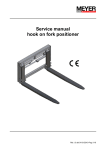
BAR FORKS POSITIONER WITH SHIFT AND
FORK SUPPORTS FEM SG-F MODEL
1 DESCRIPTION AND OPERATION
1.1 Positioner
2 ASSEMBLY INSTRUCTIONS
2.1 Positioner
2.2 Hydraulic system
2.3 Forks assembly and disassembly
2.4 Safety grid assembly
2.5 Testing
3 USER INSTRUCTIONS
3.1 Controls and recommendations
3.2 Manoeuvres to avoid
3.3 Prohibited manoeuvres
4 MAINTENANCE
4.1 Introduction
4.2 Scheduled maintenance
4.3 Extraordinary maintenance
4.4 Hydraulic system layout
5 TROUBLESHOOTING
6 RECYCLING
7 WARRANTY
Revision 01
dated 30-10-13
1 / 22
BAR FORKS POSITIONER WITH SHIFT AND
FORK SUPPORTS FEM SG-F MODEL
1 DESCRIPTION AND OPERATION
Fig.001
1.1 Positioner (FIG.001)
Device for positioning the loading forks (the load is supported by the chrome plated bars - super clean material 42CrMo4) with cylinder-driven
supports
The loading forks are hooked to the FEM of the fork support.
The supports are operated by cylinders sliding on a chrome bar with self-lubricating INA bushings. The supports are equipped with scrapers
and grease nipples to lubricate the bushings' chamber should it be necessary.
The screws and fittings are surface treated to prevent any attack by rust.
A safety grid can be applied by means of bolts and washers (without any welding and/or drilling).
The hydraulic system is connected via inlets positioned depending on the type of forklift mast. The connection fittings have 24° cone metric
thread DIN 3861 (12L or 15L). The seal of the fittings for the positioner hydraulic system is made with O-ring and retaining washer. The
hydraulic system for the positioning of the forks is equipped with a valve to ensure a perfect synchronism of the forks. The side-shift is
performed by means of an additional cylinder to optimize the movement.
2 ASSEMBLY INSTRUCTIONS
2.1 Integral Positioner
Assemble the positioner onto the plate of the forklift according to the instructions of the mast itself. Connect the system on the mast of the
forklift to the fittings of the equipment, tightening according to the regulations of the fittings used.
Revision 01
dated 30-10-13
2 / 22
BAR FORKS POSITIONER WITH SHIFT AND
FORK SUPPORTS FEM SG-F MODEL
2.2 Hydraulic system (Fig.002)
2.2.1 Connect, with flexible hoses complete with terminal fittings, the system on the mast of the forklift to fittings "Q1 (forks opening)" and "Q2
(forks closure)", Q3 (left side-shift)", Q4 (right side-shift) of the equipment, tightening the fittings used according to regulations.
2.2.2 Perform some test movements to check the perfect hydraulic seal of the fittings, the speed and the synchronism of the forks movement.
In the event of an oil leak, remove the affected fittings and clean them thoroughly. The synchronism of the forks is guaranteed by the valve.
See the table at the end of section 4.4 for the flow rates of the oil and recommended pressures.
2.2.3 At this point perform some unloaded side-shift manoeuvres, as far as the end of stroke in both directions and hold under pressure for a
few seconds. Then carry out a leak-proof control of the hydraulic connections. Any oil leaks require the disassembly and cleaning of the
fittings. Tighten them to the correct torque in accordance with the regulations.
Q3
Q1
Q4
Q2
Fig.002
Revision 01
dated 30-10-13
3 / 22
BAR FORKS POSITIONER WITH SHIFT AND
FORK SUPPORTS FEM SG-F MODEL
2.3 Forks disassembly and assembly
2.4.0 Hook the fork support with a rope suitable for the weight to be handled
2.4.1 Secure nut "c" with hex wrench "a" on the ear and loosen the front nut "d" with socket wrench "b".
(Fig.004)
2.4.2 Remove cover “X” by loosening the 4 screws with an mm Allen key. (Fig.005)
2.4.3 Attach the fork support with a cable.
2.4.4 Withdraw the rod “Y”. (Fig.005)
2.4.5 Withdraw the fork support. (Fig.005)
2.4.6 For assembly, position the fork support and fully insert rod “Y”. (Fig.005)
2.4.7 Repeat the operations in reverse from point 2.4.3 to point 2.4.1
b
Fig.004
Fig.005
d
c
X
Y
a
a
Revision 01
dated 30-10-13
4 / 22
BAR FORKS POSITIONER WITH SHIFT AND
FORK SUPPORTS FEM SG-F MODEL
2.4 Safety grid assembly (Fig.006)
2.4.1 Position the grid on the plates welded to the frame.
Bolt the grid with TCEI M16x50 Cl. screws 10.9
UNI 5931 (DIN 912) and Ø17x24 knurled washers
as in the picture.
Tightening torque 190Nm (133 Ft/Lbs).
2.5 Final Testing
After having completed procedures as per point 2.1, 2.2,
2.3, and possibly 2.4 , perform a few full travel side-shift
manoeuvres (not fork positioning) going to the end stop
and exercising pressure for a few seconds with the
maximum rated load on the forks.
Check the perfect seal of the hydraulic connections.
Any small oil leaks require the disassembly and cleaning
of the fittings.
Tighten them to the correct torque in accordance with
the regulations.
Fig.006
Revision 01
dated 30-10-13
5 / 22
BAR FORKS POSITIONER WITH SHIFT AND
FORK SUPPORTS FEM SG-F MODEL
3 USER INSTRUCTIONS
3.1 Controls and recommendations
- Introduce the loaded fork as centrally as possible
- Keep the load close to the ground for greater stability of the forklift when manoeuvring
- Keep the load tilted (tips of the fork raised) during the movement of the forklift
- Act gently on the command levers to avoid a sudden burst of pressure in the hydraulic circuit compromising the stability of the load
- Adapt the speed of the forklift to the stability and nature of the load and the difficulties caused by spaces and dimensions
- Pay attention to inclined surfaces and the unevenness of the ground since these limit the stability of the load
- Before introducing the forks, adjust their position so that no force is exerted against the foot of the pallet
3.2 Manoeuvres to avoid
- Moving loads in excess of the nominal load
- Moving an unstable load
- Picking up a load with a single fork even if of a low weight
- Moving a flanked load using the load already on the forks
- Performing forklift movements or manoeuvres fast with the load lifted high
- Performing side-shift or positioning travel of the forks with the load on the forks and forklift moving
- Follow al other instructions indicated in the forklift's user manual
3.3 Prohibited manoeuvres
- It is not a clamp (do not to use the forks to secure the load in opening or closing)
- Use the equipment for purposes other than those for which it was designed
- Operate the movements control lever when the equipment is under maintenance
- Use the forklift if visibility is poor due to the oversize of the load
- Tamper with the equipment
- Linger in the working area of the equipment or the forklift;
- Use the equipment if the structure is deformed, however slight, or there is a malfunction
- Follow al other instructions indicated in the forklift's user manual
Revision 01
dated 30-10-13
6 / 22
BAR FORKS POSITIONER WITH SHIFT AND
FORK SUPPORTS FEM SG-F MODEL
4 MAINTENANCE
4.1 Introduction
The equipment is delivered with guides lubricated with high quality grease, so as to ensure normal adjustment and polishing of the sliding
surfaces in the initial period of operation. The user should grease the bushings sliding zone on the chromed bar.
The recommended lubricant is ISO X M2 grease (SHELL ALVANIA GREASE R2 or equivalent).
For the use of the equipment in excessively dusty environments ISO CB 32 oil is recommended (ESSO NUTO 32 or equivalent).
The maintenance indicated below relates to the correct use of equipment in a slightly dusty environment.
Revision 01
dated 30-10-13
7 / 22
BAR FORKS POSITIONER WITH SHIFT AND
FORK SUPPORTS FEM SG-F MODEL
4.2 Scheduled maintenance (Fig.007)
4.2.1 Every 1000 hours.
- Check the screw tightness torque at points “C2”. (17 mm Allen key; tightening torque 700 Nm).
- Check the screw tightness torque at points “C3” (12 mm Allen key; tightening torque 235Nm ).
- Check the hydraulic seal of the fittings.
- Greasing in points “g1”, ”g2”.
- Check the general condition of the equipment.
- Specific control of the condition of the hoses.
Control of the fork support rollers integrity.
- Control the hydraulic connections (if necessary, tighten the fittings to the cylinders according to the regulations of the fittings used).
- check on the sealing of cylinder gaskets (if necessary or as a result of a leak, dismantle the cylinders according to the instructions provided at
points 4.3.1, 4.3.5).
C2
Fig.007
g2
g2
C3
g2
g1
g1
g2
C2
Revision 01
dated 30-10-13
8 / 22
BAR FORKS POSITIONER WITH SHIFT AND
FORK SUPPORTS FEM SG-F MODEL
4.2.2 Every 2000 hours
- In addition to that indicated in the previous point, carry out:
- The control of the cylinder stems and the guide bushings; the scratched or dented stem and scratched or worn bushings, as well as the
excessive play of the stem (> 0.25 mm. or 0.001 inches) requires the replacement of parts.
- Checking of sliding rollers
- Replace the shoes when the thickness is less than 4.5 mm, even only of one side.
Revision 01
dated 30-10-13
9 / 22
BAR FORKS POSITIONER WITH SHIFT AND
FORK SUPPORTS FEM SG-F MODEL
4.3 EXTRAORDINARY MAINTENANCE
U01
U01
U02
Fig.008
4.3.1 Preliminary operations
- Before performing any extraordinary maintenance, turn off the forklift and remove the pressure in the supply circuit.
- Make sure that the pump is not engaged and the lever of the distributor is not operated during the entire maintenance operation.
4.3.2 Disassembly of the fork shift right cylinder (Driver's view) (Fig.008)
- Remove the hydraulic circuit connection pipes from the right cylinder (Driver's view) observing the precautions mentioned in section 4.3.1
- Hold the opposite hex with the ch50 wrench "UO2" and loosen nut with socket wrench “U02” ch50.
- Loosen the nut on the bulkhead with socket wrench ch50 “U01”.
- Remove the cylinder.
To reassemble the cylinder perform the operations in reverse order.
Revision 01
dated 30-10-13
10 / 22
BAR FORKS POSITIONER WITH SHIFT AND
FORK SUPPORTS FEM SG-F MODEL
4.3.3 Disassembly of the fork shift left cylinder (Driver's view) (Fig.009)
U02
U02
U02
Fig.009
- Remove the hydraulic circuit connection pipes from the left cylinder (Driver's view) observing the precautions mentioned in section 4.3.1
- Hold the opposite hex with the ch50 wrench "U02" and loosen the nut with socket wrench “U02” ch50.
- Loosen the nut on the bulkhead with socket wrench ch50 “U01”.
- Remove the cylinder.
To reassemble the cylinder perform the operations in reverse order.
Revision 01
dated 30-10-13
11 / 22
BAR FORKS POSITIONER WITH SHIFT AND
FORK SUPPORTS FEM SG-F MODEL
4.3.4 Disassembly of the positioner side-shift cylinder (Fig.010)
- Fully open the fork.
- Switch off the forklift, release the pressure in the feeding circuit, make sure that during the intervention the pump does not get
engaged and that the distributor's lever is not activated.
- Remove the hydraulic circuit connection pipes “T1” and “T2” from the cylinder "C" observing the precautions mentioned in point 4.3.1
- Remove the two snap rings “S1” and “S2” with the pliers.
- Rotate the cylinder as indicated by the arrow in Fig.010 to remove it from the pins.
- Remove the cylinder.
- For reassembling, carry out operations in the reverse order
T1
Fig.010
T2
C
S1
S2
Revision 01
dated 30-10-13
12 / 22
BAR FORKS POSITIONER WITH SHIFT AND
FORK SUPPORTS FEM SG-F MODEL
4.3.4 Disassembly and reassembly of the fork support lower sliding roller
C
D
B
A
- Having removed the fork support (see point 2.4), loosen dowel "A" with a 4 mm Allen key
- Extract the pin “B”.
- Remove the roller “C”.
- Check the wear of the bushing “D” and replace it if necessary.
- Having carefully cleaned, reassemble by performing all the operations described above in reverse order.
Revision 01
dated 30-10-13
13 / 22
BAR FORKS POSITIONER WITH SHIFT AND
FORK SUPPORTS FEM SG-F MODEL
4.3.5 Replacement of the fork shift cylinder seal (Fig.011)
cs04
cs06
cs04
cs05
cs03
cs03
cs06
Cs01
cs02
Fig.011
Det.”A”
- After having performed one or more operations as per point 4.3.2 and/or 4.3.3.
- Unscrew the cap "cs05", with a pin wrench, and remove it along with the stem "cs02" and parts "cs03", "cs04" and "cs06" of the cylinder
casing
- Seal replacement procedures “cs01”, “cs03”, “cs04”, “cs06”.
- The reassembly of the cylinder must be performed in reverse order to that indicated above, with particular attention to cleaning and
checking the exact orientation of the seals “cs03”, “cs04”, “cs06” (Det. "A")
- The same disassembly and replacement method of seals is valid for the right cylinder (driver's view) of the supply system.
Revision 01
dated 30-10-13
14 / 22
BAR FORKS POSITIONER WITH SHIFT AND
FORK SUPPORTS FEM SG-F MODEL
4.3.6 Replacement of gaskets and of the shift cylinder's ball joint (Fig.012)
cs01
cs07
cs04
cs05
cs03
cs02
Cs10
cs09
cs09
Cs10
cs08
cs08
cs06
Fig.012
- After having performed one or more operations as per point 4.3.2 and/or 4.3.3.
- Unscrew the "cs05” plug, with a pin wrench.
- Extract spring pin “cs07” and unscrew piston “cs08”.
- Extract stem “cs02” and parts “cs03” , “cs04” and “cs06” from the cylinder casing
Det. “A”
- Proceed with the replacement of gaskets “cs01”, “cs08”, “cs04”, “cs06”,” cs03”
- To remove ball joint “cs09” extract seeger “cs10”
- The reassembly of the cylinder must be performed in reverse order to that indicated above, with particular attention to cleaning and
checking the exact orientation of the seals “cs03”, “cs04”, “cs06” (Det. "A")
Revision 01
dated 30-10-13
15 / 22
BAR FORKS POSITIONER WITH SHIFT AND
FORK SUPPORTS FEM SG-F MODEL
4.3.6 Equipment restoration
After each maintenance operation, restore the equipment to the initial condition and perform the tests referred to in point 2.5.
4.4 HYDRAULIC SYSTEM LAYOUT (forks positioning) (Fig.013)
Q2
Q3
Q1
Q4
Q4
Q3
Q1
Q2
- To spread/open the forks, introduce pressure in "Q1"
- To approach/close the forks, introduce pressure in "Q2"
- Left shift (view from the operator side) “Q3”- Right shift (view from the operator side) “Q4"
Revision 01
dated 30-10-13
16 / 22
BAR FORKS POSITIONER WITH SHIFT AND
FORK SUPPORTS FEM SG-F MODEL
Hydraulic layout
Fig.013
Revision 01
dated 30-10-13
17 / 22
BAR FORKS POSITIONER WITH SHIFT AND
FORK SUPPORTS FEM SG-F MODEL
Table of the recommended oil flow rates and operating pressures.
•
Fork positioner oil flow rate:
minimum 30 l/min. recommended 40 l/min. maximum 60 l/min
•
Hydraulic functions and recommended pressures:
Fork positioner pressure Min. 14 MPa (maximum pressure at the distributor 25 MPa)
side-shifter pressure min. 12 MPa, max. 22 MPa (maximum pressure at the distributor 25 MPa)
Revision 01
dated 30-10-13
18 / 22
BAR FORKS POSITIONER WITH SHIFT AND
FORK SUPPORTS FEM SG-F MODEL
5 TROUBLESHOOTING
FAULTS
5.1 The forks do not shift
CAUSES
Obstructions or accumulation of dirt on sliding
tracks
Insufficient hydraulic pressure
Hydraulic circuit blocked or broken
Leak inside the cylinder (worn seals)
5.2 The shifting of the forks is too slow
Insufficient oil flow
Obstructions in the hydraulic circuit
Leak inside the cylinder (worn seals)
5.3 The shifting of the forks is too fast
High oil flow
5.4 The forks do not shift in a
synchronized manner
Obstructions or accumulation of dirt on sliding
tracks
5.5 The side-shift does not occur at all
Frame deformed
Mud or other obstruction on the track of the
lower rollers
Deteriorated hoses
Obstruction in the hydraulic circuit
Insufficient pressure
Deteriorated pump
SOLUTION
Remove the obstructions, clean and grease the sliding
tracks
Control and/or regulation of the pressure delivered by
the forklift's pump.
Eliminate the obstruction or replace the damaged pipe
Control and possible replacement of the seals, see
point “4.3.2” and/or “4.3.3” and “4.3.5”
Control and regulation of the flow delivered by the
hydraulic circuit. Adjust the forklift's oil flow.
Eliminate the obstruction or replace the damaged pipe
Control and possible replacement of the seals, see
point “4.3.2” and/or “4.3.3” and “4.3.5”
Control and regulation of the flow delivered by the
hydraulic circuit. Adjust the forklift's oil flow.
Remove the obstructions, clean and grease the sliding
tracks
Replace the frame removing it as in point 4.3.5
Clean the track and lubricate shoes as in point 4.2.1
Replace the pipes
Eliminate the obstruction
Increase the pressure
Repair or replace the pump of the forklift
Revision 01
dated 30-10-13
19 / 22
BAR FORKS POSITIONER WITH SHIFT AND
FORK SUPPORTS FEM SG-F MODEL
FAULTS
5.6 The side-shift is too slow
5.7 The side-shift occurs with jolts or
irregularly
CAUSES
SOLUTION
Worn sliding rollers
After cleaning replace the rollers.
Emulsified oil, the pump draws in air
Deteriorated pump
Insufficient pressure
Check the oil level in the tank of the forklift
Repair or replace the pump of the forklift
Increase the pressure
Air in the hydraulic system
Bleed the forklift's system and check the oil level
Air in the system
Bleed the system
NOTE: If there are difficulties or in the case of defects other than those listed, please contact BOLZONI Technical Support Service.
Revision 01
dated 30-10-13
20 / 22
BAR FORKS POSITIONER WITH SHIFT AND
FORK SUPPORTS FEM SG-F MODEL
6 RECYCLING
6.1 Replaced parts should be disposed of, as in the case of complete destruction, separately depending on the nature of the material and in
compliance with the requirements of the law on the disposal of solid industrial waste.
Frame unit
Fasteners, piping and other components
Welded frame
Steel
Hoses and fittings
Nylon and steel
Supports
Steel
Hydraulic oil
Dispose of in compliance with local
regulations
Fastening of cylinders
Steel
Bushings
Steel and Teflon
Chrome bar
Steel and chrome
Pins, screws, bolts, snap rings
Steel
Paint
Epoxy polyester
O-ring
rubber
Cylinders
Steel and chrome
Seals
Polyurethane
Shift cylinder stems
Steel and chrome
Shoes
Polyamide
Revision 01
dated 30-10-13
21 / 22
BAR FORKS POSITIONER WITH SHIFT AND
FORK SUPPORTS FEM SG-F MODEL
7 WARRANTY
BOLZONI S.p.A. warrants all its products for 12 months for an 8-hour-a-day use every working day starting from the date of shipment. If used more
than 8 hours per day the warranty period shall be reduced proportionately. The warranty is limited to replacing the parts that the company deems
defective due to material or machining defects ex BOLZONI S.p.A. works and does not include labour or travel costs for replacing said parts.
It is further understood that recognition of the warranty is void if the anomaly results from an inappropriate use of the product, if commissioning was not
carried out according to BOLZONI S.p.A specifications or if non-original parts have been assembled on BOLZONI S.p.A. products. BOLZONI S.p.A
products. are not guaranteed for uses that exceed the ratings stated on the plates and in the technical documentation attached to the order.
All the equipment manufactured by BOLZONI S.p.A. is covered by insurance for any damage caused to third parties by defective parts or their
malfunction; damage arising from improper use or misuse of the equipment is not covered.
Revision 01
dated 30-10-13
22 / 22


