1
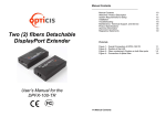
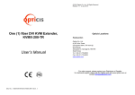
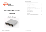
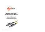
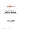
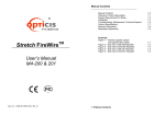
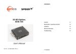
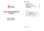
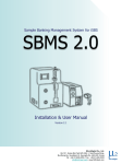
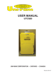
ㅕ Manual Contents __________________________________________ Manual Contents Welcome! Product Description System Requirements for Setup Installation Troubleshooting Maintenance, Technical Support, and Service Product Specifications Warranty Information Regulatory Statements Two (2) fibers Detachable HDMI Extender 1-0 1-1 1-2 1-3 1-5 1-6 1-7 1-8 1-9 Pictorials Figure 1 – Overall Connection of HDFX-250-TR Figure 2 – Position of the LED Figure 3 – Fiber numbering & Caution on both fiber ports Figure 4 – Connection of optical fiber User’s Manual for the HDFX-250-TR 1-0 Manual Contents 1-1 1-3 1-3 1-4 Welcome! Congratulations on your purchase of the two (2) fibers HDMI extender, HDFX250-TR. This manual contains information that will assist you in installing and operating the product. System Requirements for Setup □ Hardware requirements ▪ DVD, Blu-Ray or media receiver with standard HDMI ports. ▪ In case of using PC as a graphic source, regardless of OS version embedded HDMI ports. ▪ Only HDMI TVs or monitors are applicable. ▪ Proper initial trial of the entire platform with its application using a short length copper cable is recommended prior to install with the optical link. □ Software requirements ▪ No special needs, but make sure that media contents protected by HDCP should be played with HDCP certified players and TVs. □ Power Technical Advisory ▪ Enclosed Power Adaptors and USB cables supply power to both Transmitter and Receiver. □ Connection Advisory ▪ It is highly recommend that HDMI media source is directly connected into HDMI display output via HDFX-250-TR without connection to incompatible distributor, switcher and selector. Product Description New optical HDMI extender, HDFX-250-TR is designed compact enough to be fitted into various installation environments, and enables to transmit WUXGA (1920x1200) or 1080p at 60Hz signal up to 300m (985feet) over two (2) LC multi-mode fibers, avoiding any tricks like scaling or data compression for lessening a burden of data transmission. The pure fiber connection by two (2) LC fibers connector between transmitter and receiver, gives clean, secure and easy installation with perfect electrical isolation, but without electrical hazard and interference. The HDFX-250-TR can be operated by both USB power by plugging the USB cable and DC power included as a shipping group. Figure 1 – Overall Connection of HDFX-250-TR The Shipping Group of HDFX-250-TR; One (1) Transmitter (Tx) and One (1) Receiver (Rx) Two (2) HDMI copper cables (0.3m) Two (2) USB to HDMI plug Cables Two (2) DC +5V,1A power adapters User’s Manual Option Product: LC Multi-mode fiber 1-1 Welcome, Product Description 1-2 System Requirements for Setup Installation Note1: The maximum extension length by multi-mode fiber is 300 meters. Important: Please keep the installation procedure below. Improper or no operation may result if the start-up sequence is not correctly followed. Note2: Be recommended NOT to use any intermediate cable or adapter between them to avoid undesirable performance degradation. Step 1 Carefully unpack the contents in the shipping group. Step 2 Power on the HDMI source and display. Power on both transmitter and receiver by using USB power cable or DC power adapter. Step 3 Then, the LED (Green color) will begin to blink once a second for three (3) times regularly on both sides. Fig Figure 4 – Connection of optical fiber Position of the LED Figure 2 – Position of the LED Step 4 Connect two (2) LC optical fibers between the transmitter and the receiver and each fiber channel shall be connected as A to A and B to B carefully. Ensure the duplex connectors are fully engaged and then, the top LED will begin to blink regularly. Step 5 Connect the transmitter to the HDMI source over HDMI copper cable. Step 6 Connect the receiver to the HDMI display over HDMI copper cable. Note: If the connectors are fully engaged, the bottom LED will turn on. Step 7 If the system does not work properly, go to the page 1-5 trouble shooting. Fig Figure 3 – Fiber numbering & Caution on both fiber ports 1-4 Installation 1-3 Installation Troubleshooting Maintenance The display shows only black screen. - Ensure that all plugs and jacks used by USB power cables or external power supplies are firmly connected. Ensure that the LED ON. No special maintenance is required for the optical system cables and power supplies. Ensure that the cables and power modules are stored or used in a benign environment free from liquid or dirt contamination. - Ensure that the HDMI ports are firmly plugged in to the source and display. - Ensure that the transmitter and receiver modules plugged correctly to the source and display, respectively. There are no user serviceable parts. Refer all service and repair issues to Opticis or its authorized distributor. - Check if the HDMI source and display are powered on and properly booted. - Reset the system by de-plugging and re-plugging the transmitter HDMI port or receiver HDMI port, or by de-plugging and re-plugging the USB power cables that are plugged of transmitter and receiver module Technical Support and Service - Re-boot up the system while connecting the module. Screen is distorted or displays noises. - Check if the graphic resolution is properly set. Go to the display properties and tap For commercial or general product support, contact your reseller. For technical service, contact Opticis by email [email protected] or visit its website at www.opticis.com. the settings. Ensure that the resolution sets less than WUXGA (1920x1200) at 60Hz refresh ratio. - Reset the system - Power down, disconnect and reconnect the optical system cable or DC power adaptors, and power up 1-5 Troubleshooting 1-6 Maintenance, Technical Support, and Service Product Specifications Compliance with HDMI standard: supports HDMI 1.3a up to 36-bit in color depth, using fiber-optic communication link and fully function in HDCP. Extension limit: 300 meters (985feet) for WUXGA (1920x1200) or 1080p at 60Hz refresh rate over two (2) LC multi-mode fibers (50/125um). Complies with CEC, EDID & HDCP Mechanical specifications of Tx and Rx boxes Dimensions(WDH): 72mm x 35mm x 16mm Environmental Specifications Operating temperature: 0°C to 50°C Storage temperature: -30°C to 70°C Humidity: 10% to 80% AC/DC Power Adapter Power Input: AC 100-240V, 50/60Hz. Power Output: +5 V, 1A SMPS DC-power Adapter Cord DC Jack: Core is + 5 V and outer is GND. Certification: FCC, CE Warranty Information 1 (One) Year Warranty Opticis warrants this optical DP module to be free from defects in workmanshi p and materials, under normal use and service, for a period of one (1) year fro m the date of purchase from Opticis or its authorized resellers. If a product does not work as warranted during the applicable warranty period, Opticis shall, at its option and expense, repair the defective product or part, d eliver to customer an equivalent product or part to replace the defective item, or refund to customer the purchase price paid for the defective product. All products that are replaced will become the property of Opticis. Replacement products may be new or reconditioned. Any replaced or repaired product or part has a ninety (90) day warranty or the reminder of the initial warranty period, whichever is longer. Opticis shall not be responsible for any software, firmware, information, or me mory data of customer contained in, stored on, or integrated with any product s returned to Opticis for repair under warranty or not. Warranty Limitation and Exclusion Opticis shall have no further obligation under the foregoing limited warranty if the product has been damaged due to abuse, misuse, neglect, accident, unusual physical or electrical stress, unauthorized modifications, tampering, alterations, or service other than by Opticis or its authorized agents, causes other than from ordinary use or failure to properly use the product in the application for which said product is intended. Dispose of Old Electrical & Electronic Equipment (Applicable in the European Union and other European countries with separate systems) This symbol on the product or on its packaging indicates that this product shall not be treated as household waste. Instead it shall be handed over to the applicable collection point for the recycling of electrical and electronic equipment. By ensuring this product is disposed of correctly, you will help prevent potential negative consequences for the environment and human health, which could otherwise be caused by inappropriate waste handling of this product. The recycling of materials will help to conserve natural resources. For more detailed information about recycling of this product, please contact your local city office, your household waste disposal service or the shop where you purchased the product. 1-7 Product Specifications 1-8 Warranty Information FCC/CE Statement for regulation of Electro-magnetic emission This device complies with part 15 of FCC Rules. Operation is subject to the following two conditions: (1) this device may not cause harmful interference, and (2) this device must accept any interference received, including interference that may cause undesired operation. This equipment has been tested and found to comply with the limits for a Class A digital device, pursuant to part 15 and 2 of FCC Rules, EN 55022/55024/61000-3 for CE certification. These limits are designed to provide reasonable protection against harmful interference when the equipment is operated in a residential installation. This equipment generates, uses, and can radiate radio frequency energy and. if not installed and used in accordance with the instruction guide, may cause harmful interference to radio communications. However, there is no guarantee that interference will not occur in a particular installation. If this equipment does cause harmful interference to radio or television reception, which can be determined by turning the equipment off and on, the user is encouraged to try to correct the interference by one or more of the following measures: Re-orient or relocate the receiving antenna. Increase the separation between the equipment and the receiver. Connect the equipment into an outlet on a circuit different from that to which the receiver is connected. Consult a service representative for help. © 2013 Opticis Co., Ltd. All Rights Reserved Revision 1.0. April. 2013 Opticis Locations OPTICIS HQ Opticis Co., Ltd. # 16Fl, Kins Tower, 8 Seongnam-daero, 331 beon-gil, Bundang-gu , Sungnam-si, Gyunggi-do, 463-782 Rep. of Korea Te l: +82 (31) 719-8033 Fax: +82 (31) 719-8032 www.opticis.com Properly shielded and grounded cables and connectors must be used in order to comply with FCC/CE emission limits. Changes or modifications not expressly approved by the party responsible for compliance could void the user s authority to operate the equipment. For order support, please contact your Distributor or Reseller. For technical support, check with the Opticis web site www.opticis.com or contact [email protected] 1-9 Regulatory Statements