1
Department of
Control Engineering
Aalborg University, Denmark
Fredrik Bajers Vej 7, 9220 Aalborg Ø
TITLE: Open Home Automation Project
PROJECT PERIOD:
1st of September 2003 - 3rd of June 2004
SYNOPSIS:
PROJECT GROUP:
1032i
SEMESTER:
9-10th semester
Distributed Real Time Systems
GROUP MEMBERS:
Bendtsen, Kim Led
Christensen, Mikkel Lønnerup
SUPERVISOR:
Schiøler, Henrik
NUMBER OF COPIES: 10
NUMBER OF PAGES: 195 pages
REPORT: 183 pages
APPENDIX: 12 pages
The purpose of this master thesis was to create
scalable network protocols suitable for home
automation applications. The context of the
thesis was based in the "Open Home Automation Project" (OHAP) concept where protocols
are available for free and could be used to control and monitor all devices used in home automation.
The thesis starts by describing several application visions regarding a house filled with home
automation devices. This is used to identify
the needed protocols and their requirements.
Protocols from other computer systems are examined in order to find properties that would
fit an OHAP system. Selected protocols are
then designed for use in a prototype implementation.
The prototype run on a PC environment and is
partially ported to an embedded platform.
Department of
Control Engineering
Aalborg University, Denmark
Fredrik Bajers Vej 7, 9220 Aalborg Ø
TITEL: Open Home Automation Project
PROJEKT PERIODE:
1. september 2003 - 3 juni 2004
SYNOPSIS:
PROJEKT GRUPPE:
1032i
SEMESTER:
9-10. semester
Distribuerede systemer
GRUPPE MEDLEMMER:
Bendtsen, Kim Led
Christensen, Mikkel Lønnerup
VEJLEDER:
Schiøler, Henrik
ANTAL KOPIER: 10
ANTAL SIDER: 195 sider
RAPPORT: 183 sider
APPENDIKS: 12 sider
Formålet ved dette afgangs projekt var at udvikle skalerbare netværks protokoller velegnede til brug i hjemme automations produkter. Konteksten for projektet er "Open Home
Automation Project" (OHAP) konceptet hvor
protokoller er frit tilgængelige til brug for kontrol og overvågning af hjemme automationsenheder.
Afgangs projektet begynder med at beskrive
adskillelige produkt visioner egnet til et hus
fyldt med hjemme automation. Dette er brugt
til at identificere de nødvendige protokoller og
tilhørende krav. Protokoller fra andre computer systemer er analyseret for at find egenskaber der vil passe i et OHAP system. Udvalgte protokoller er derefter designet til brug i en
protype implementering.
Prototypen kører i et PC miljø og er delvist
porteret til en embedded platform.
Group 1032i
Preface
This master thesis has been written by group 1032i in the two final semesters of the M.Sc. programme
Distributed Real time Systems at the Department of Control Engineering, Aalborg University.
The purpose of the thesis is to create an analysis, design and a prototype implementation of a home
automation system. To do this, different topics and skills from a broad range of the education is used.
Through out the thesis citations is made with two or three characthers and a year, e.g. [blu04]. The
fields of a packet, a function call or a message is typed in true types e.g. MESSAGE.
Enclosed in this thesis is a CD-ROM which contains the source code for the developed software and
SDL diagrams, schematics for the embedded hardware along with this thesis in electronical format
including the LATEX source.
Acknowledgments
This project was proposed by Henrik Schiøler at the Department of Control Engineering, Aalborg
University, in cooperation with Jørn Eskildsen, Amfitech Aps. We thank Henrik Schiøler for great
supervision and help. Furthermore we thank Jørn Eskildsen for giving us inspiration, commenting
our work and use of photo material for the thesis.
Group 1032i at Aalborg University.
Signatures:
Kim Led Bendtsen
Mikkel Lønnerup Christensen
3
Contents
I
Introduction
13
1
Introduction
15
1.1
Introduction . . . . . . . . . . . . . . . . . . . . . . . . . . . . . . . . . . . . . . .
15
1.2
Reading Guide . . . . . . . . . . . . . . . . . . . . . . . . . . . . . . . . . . . . .
16
1.2.1
Part I - Introduction . . . . . . . . . . . . . . . . . . . . . . . . . . . . . . .
16
1.2.2
Part II - OHAP Application Framework . . . . . . . . . . . . . . . . . . . .
16
1.2.3
Part III - OHAP Protocol Stack . . . . . . . . . . . . . . . . . . . . . . . .
17
1.2.4
Part IV - Prototype . . . . . . . . . . . . . . . . . . . . . . . . . . . . . . .
17
1.2.5
Part V - Project Closure . . . . . . . . . . . . . . . . . . . . . . . . . . . .
17
1.2.6
Part VI - Appendix . . . . . . . . . . . . . . . . . . . . . . . . . . . . . . .
17
1.2.7
Reading Paths . . . . . . . . . . . . . . . . . . . . . . . . . . . . . . . . . .
17
2
Preliminary Analysis
19
2.1
Introduction . . . . . . . . . . . . . . . . . . . . . . . . . . . . . . . . . . . . . . .
19
2.2
Application Visions . . . . . . . . . . . . . . . . . . . . . . . . . . . . . . . . . . .
19
2.2.1
Door Locks . . . . . . . . . . . . . . . . . . . . . . . . . . . . . . . . . . .
19
2.2.2
Sensor Readings . . . . . . . . . . . . . . . . . . . . . . . . . . . . . . . .
21
2.2.3
Refrigerator Intelligence . . . . . . . . . . . . . . . . . . . . . . . . . . . .
21
2.2.4
Video Surveillance . . . . . . . . . . . . . . . . . . . . . . . . . . . . . . .
21
2.2.5
Intelligent Light Control . . . . . . . . . . . . . . . . . . . . . . . . . . . .
21
2.2.6
Voice Control . . . . . . . . . . . . . . . . . . . . . . . . . . . . . . . . . .
21
2.2.7
Person Surveillance . . . . . . . . . . . . . . . . . . . . . . . . . . . . . . .
22
2.2.8
Calendar Synchronization . . . . . . . . . . . . . . . . . . . . . . . . . . .
22
2.2.9
Internet Gateway . . . . . . . . . . . . . . . . . . . . . . . . . . . . . . . .
22
2.2.10 Intelligent Toys . . . . . . . . . . . . . . . . . . . . . . . . . . . . . . . . .
22
2.2.11 Heating, Ventilation and Air Conditioning (HVAC) . . . . . . . . . . . . . .
22
5
CONTENTS
2.3
2.4
2.2.12 OHAP Enabling . . . . . . . . . . . . . . . . . . . . . . . . . . . . . . . .
23
2.2.13 Overview . . . . . . . . . . . . . . . . . . . . . . . . . . . . . . . . . . . .
23
Classification . . . . . . . . . . . . . . . . . . . . . . . . . . . . . . . . . . . . . .
24
2.3.1
Application Class . . . . . . . . . . . . . . . . . . . . . . . . . . . . . . . .
24
2.3.2
Communication Class . . . . . . . . . . . . . . . . . . . . . . . . . . . . .
24
Summary . . . . . . . . . . . . . . . . . . . . . . . . . . . . . . . . . . . . . . . .
26
3 Requirement Specification
29
3.1
System Description . . . . . . . . . . . . . . . . . . . . . . . . . . . . . . . . . . .
29
3.2
System Functionality . . . . . . . . . . . . . . . . . . . . . . . . . . . . . . . . . .
29
3.2.1
User Profiles . . . . . . . . . . . . . . . . . . . . . . . . . . . . . . . . . .
31
3.2.2
Manufacturer Setup . . . . . . . . . . . . . . . . . . . . . . . . . . . . . . .
31
3.2.3
Device Setup and Service . . . . . . . . . . . . . . . . . . . . . . . . . . .
31
3.2.4
Daily Usage . . . . . . . . . . . . . . . . . . . . . . . . . . . . . . . . . . .
33
3.3
Use Case Specification . . . . . . . . . . . . . . . . . . . . . . . . . . . . . . . . .
33
3.4
System Requirements . . . . . . . . . . . . . . . . . . . . . . . . . . . . . . . . . .
40
3.4.1
General requirements . . . . . . . . . . . . . . . . . . . . . . . . . . . . . .
40
3.4.2
Formal Requirements . . . . . . . . . . . . . . . . . . . . . . . . . . . . . .
44
Summary . . . . . . . . . . . . . . . . . . . . . . . . . . . . . . . . . . . . . . . .
45
3.5.1
45
3.5
Demarcation . . . . . . . . . . . . . . . . . . . . . . . . . . . . . . . . . .
II OHAP Application Framework
47
4 Analysis of the OHAP Application Framework
49
6
4.1
Profiles . . . . . . . . . . . . . . . . . . . . . . . . . . . . . . . . . . . . . . . . .
49
4.2
Service Discovery . . . . . . . . . . . . . . . . . . . . . . . . . . . . . . . . . . . .
50
4.2.1
UPnP - Universal Plug and Play . . . . . . . . . . . . . . . . . . . . . . . .
50
4.2.2
Jini . . . . . . . . . . . . . . . . . . . . . . . . . . . . . . . . . . . . . . .
50
4.2.3
HAVi - Home Audio/Video Interoperability . . . . . . . . . . . . . . . . . .
51
4.3
Mobile Agents . . . . . . . . . . . . . . . . . . . . . . . . . . . . . . . . . . . . .
51
4.4
Internet Enabling . . . . . . . . . . . . . . . . . . . . . . . . . . . . . . . . . . . .
51
4.5
Automatic Network Configuration . . . . . . . . . . . . . . . . . . . . . . . . . . .
52
4.5.1
DHCP . . . . . . . . . . . . . . . . . . . . . . . . . . . . . . . . . . . . . .
52
4.5.2
Zero Configuration . . . . . . . . . . . . . . . . . . . . . . . . . . . . . . .
53
Group 1032i
4.6
5
4.5.3
IPv6 Auto Configuration . . . . . . . . . . . . . . . . . . . . . . . . . . . .
53
4.5.4
The Buddy System . . . . . . . . . . . . . . . . . . . . . . . . . . . . . . .
54
Summary . . . . . . . . . . . . . . . . . . . . . . . . . . . . . . . . . . . . . . . .
54
4.6.1
54
Assumptions About Lower Protocol Layers . . . . . . . . . . . . . . . . . .
Automatic Network Configuration
55
5.1
Introduction . . . . . . . . . . . . . . . . . . . . . . . . . . . . . . . . . . . . . . .
55
5.2
Preliminary Design . . . . . . . . . . . . . . . . . . . . . . . . . . . . . . . . . . .
55
5.2.1
Complexity of DHCP . . . . . . . . . . . . . . . . . . . . . . . . . . . . . .
56
5.2.2
Complexity of The Buddy System . . . . . . . . . . . . . . . . . . . . . . .
56
5.2.3
Conclusion of the Complexity Analysis . . . . . . . . . . . . . . . . . . . .
60
5.3
Service Specification . . . . . . . . . . . . . . . . . . . . . . . . . . . . . . . . . .
67
5.4
Protocol Vocabulary . . . . . . . . . . . . . . . . . . . . . . . . . . . . . . . . . . .
67
5.5
Packet Format . . . . . . . . . . . . . . . . . . . . . . . . . . . . . . . . . . . . . .
67
5.5.1
ANCP Options . . . . . . . . . . . . . . . . . . . . . . . . . . . . . . . . .
69
Procedure Rules . . . . . . . . . . . . . . . . . . . . . . . . . . . . . . . . . . . . .
70
5.6.1
Configuration Process . . . . . . . . . . . . . . . . . . . . . . . . . . . . .
70
5.6.2
Disconnection Process . . . . . . . . . . . . . . . . . . . . . . . . . . . . .
70
Summary . . . . . . . . . . . . . . . . . . . . . . . . . . . . . . . . . . . . . . . .
71
5.6
5.7
6
CONTENTS
Service Discovery Protocol
73
6.1
Service Specification . . . . . . . . . . . . . . . . . . . . . . . . . . . . . . . . . .
73
6.2
Protocol Vocabulary . . . . . . . . . . . . . . . . . . . . . . . . . . . . . . . . . . .
73
6.3
Packet Format . . . . . . . . . . . . . . . . . . . . . . . . . . . . . . . . . . . . . .
75
6.3.1
Query Entry . . . . . . . . . . . . . . . . . . . . . . . . . . . . . . . . . . .
77
6.3.2
Result Entry . . . . . . . . . . . . . . . . . . . . . . . . . . . . . . . . . .
79
6.3.3
Reject Entry . . . . . . . . . . . . . . . . . . . . . . . . . . . . . . . . . .
79
6.4
Procedure Rules . . . . . . . . . . . . . . . . . . . . . . . . . . . . . . . . . . . . .
81
6.5
Validation of the SDP . . . . . . . . . . . . . . . . . . . . . . . . . . . . . . . . . .
81
6.5.1
Description of System . . . . . . . . . . . . . . . . . . . . . . . . . . . . .
83
6.5.2
Description of Trigger Device . . . . . . . . . . . . . . . . . . . . . . . . .
83
6.5.3
Description of Device . . . . . . . . . . . . . . . . . . . . . . . . . . . . .
83
6.5.4
Description of Application . . . . . . . . . . . . . . . . . . . . . . . . . . .
86
6.5.5
Description of Network Layer . . . . . . . . . . . . . . . . . . . . . . . . .
87
6.5.6
Description of Medium . . . . . . . . . . . . . . . . . . . . . . . . . . . . .
88
7
CONTENTS
6.5.7
Description of SDP . . . . . . . . . . . . . . . . . . . . . . . . . . . . . . .
89
6.5.8
Results . . . . . . . . . . . . . . . . . . . . . . . . . . . . . . . . . . . . .
90
III OHAP Protocol Stack
93
7 Analysis OHAP Protocol Stack
95
7.1
Introduction . . . . . . . . . . . . . . . . . . . . . . . . . . . . . . . . . . . . . . .
95
7.2
Overview of the OPS . . . . . . . . . . . . . . . . . . . . . . . . . . . . . . . . . .
96
7.3
Addressing . . . . . . . . . . . . . . . . . . . . . . . . . . . . . . . . . . . . . . .
96
7.4
Proxy . . . . . . . . . . . . . . . . . . . . . . . . . . . . . . . . . . . . . . . . . .
97
7.5
OHAP Network and Transportation Protocol . . . . . . . . . . . . . . . . . . . . . .
99
7.6
Assumptions About the Environment of the OHAP Protocol Stack . . . . . . . . . .
99
7.7
Overview of Possible Routing Protocols . . . . . . . . . . . . . . . . . . . . . . . . 100
7.7.1
Static Routing Protocols . . . . . . . . . . . . . . . . . . . . . . . . . . . . 101
7.7.2
MANET Routing Protocols . . . . . . . . . . . . . . . . . . . . . . . . . . 101
7.7.3
Conclusion . . . . . . . . . . . . . . . . . . . . . . . . . . . . . . . . . . . 103
8 Routing Protocol
8.1
8.2
8.3
8.4
Service Specification . . . . . . . . . . . . . . . . . . . . . . . . . . . . . . . . . . 105
8.1.1
Scalability . . . . . . . . . . . . . . . . . . . . . . . . . . . . . . . . . . . 106
8.1.2
Participation Level . . . . . . . . . . . . . . . . . . . . . . . . . . . . . . . 106
Protocol Vocabulary . . . . . . . . . . . . . . . . . . . . . . . . . . . . . . . . . . . 107
8.2.1
Subnet Routing . . . . . . . . . . . . . . . . . . . . . . . . . . . . . . . . . 107
8.2.2
Inter Subnet Routing . . . . . . . . . . . . . . . . . . . . . . . . . . . . . . 108
8.2.3
Resource Aware Routing . . . . . . . . . . . . . . . . . . . . . . . . . . . . 109
8.2.4
Inter Router Protocol and Local Router Protocol . . . . . . . . . . . . . . . 111
8.2.5
Failure Scenarios . . . . . . . . . . . . . . . . . . . . . . . . . . . . . . . . 112
8.2.6
Messages . . . . . . . . . . . . . . . . . . . . . . . . . . . . . . . . . . . . 113
Packet Format . . . . . . . . . . . . . . . . . . . . . . . . . . . . . . . . . . . . . . 113
8.3.1
Node to Router . . . . . . . . . . . . . . . . . . . . . . . . . . . . . . . . . 113
8.3.2
Node To Node . . . . . . . . . . . . . . . . . . . . . . . . . . . . . . . . . 116
8.3.3
Router to Router . . . . . . . . . . . . . . . . . . . . . . . . . . . . . . . . 118
Summary . . . . . . . . . . . . . . . . . . . . . . . . . . . . . . . . . . . . . . . . 119
9 Network and Transportation Layer
8
105
121
Group 1032i
IV
CONTENTS
9.1
Service Specification . . . . . . . . . . . . . . . . . . . . . . . . . . . . . . . . . . 121
9.2
Protocol Vocabulary . . . . . . . . . . . . . . . . . . . . . . . . . . . . . . . . . . . 121
9.3
Packet Format . . . . . . . . . . . . . . . . . . . . . . . . . . . . . . . . . . . . . . 121
9.4
Procedure Rules . . . . . . . . . . . . . . . . . . . . . . . . . . . . . . . . . . . . . 124
9.5
Summary . . . . . . . . . . . . . . . . . . . . . . . . . . . . . . . . . . . . . . . . 124
Prototype
129
10 Prototype
131
11 Hardware
135
11.1 Introduction . . . . . . . . . . . . . . . . . . . . . . . . . . . . . . . . . . . . . . . 135
11.2 Requirements . . . . . . . . . . . . . . . . . . . . . . . . . . . . . . . . . . . . . . 135
11.3 System Layout . . . . . . . . . . . . . . . . . . . . . . . . . . . . . . . . . . . . . 136
11.4 Hardware Modules . . . . . . . . . . . . . . . . . . . . . . . . . . . . . . . . . . . 138
11.4.1 MOD-V2 Power Line Module . . . . . . . . . . . . . . . . . . . . . . . . . 138
11.4.2 Motorola Bluetooth Development Board 1.3 . . . . . . . . . . . . . . . . . . 139
11.4.3 PIC16F877 Microcontroller . . . . . . . . . . . . . . . . . . . . . . . . . . 139
11.5 Schematics . . . . . . . . . . . . . . . . . . . . . . . . . . . . . . . . . . . . . . . 140
11.6 Summary . . . . . . . . . . . . . . . . . . . . . . . . . . . . . . . . . . . . . . . . 140
12 Software
145
12.1 System Description . . . . . . . . . . . . . . . . . . . . . . . . . . . . . . . . . . . 145
12.1.1 Prototype OS . . . . . . . . . . . . . . . . . . . . . . . . . . . . . . . . . . 145
12.1.2 Development Principles . . . . . . . . . . . . . . . . . . . . . . . . . . . . 146
12.2 Software Design . . . . . . . . . . . . . . . . . . . . . . . . . . . . . . . . . . . . . 146
12.2.1 Class Diagram . . . . . . . . . . . . . . . . . . . . . . . . . . . . . . . . . 146
12.2.2 Message Sequence Charts . . . . . . . . . . . . . . . . . . . . . . . . . . . 148
12.2.3 State Chart Diagrams . . . . . . . . . . . . . . . . . . . . . . . . . . . . . . 152
12.3 Configuration Files . . . . . . . . . . . . . . . . . . . . . . . . . . . . . . . . . . . 158
12.4 Code Size . . . . . . . . . . . . . . . . . . . . . . . . . . . . . . . . . . . . . . . . 160
12.5 Summary . . . . . . . . . . . . . . . . . . . . . . . . . . . . . . . . . . . . . . . . 161
9
CONTENTS
V
Project Closure
13 Results
163
165
13.1 Prototype and User Application . . . . . . . . . . . . . . . . . . . . . . . . . . . . . 165
13.1.1 Embedded Prototype . . . . . . . . . . . . . . . . . . . . . . . . . . . . . . 165
13.1.2 Application . . . . . . . . . . . . . . . . . . . . . . . . . . . . . . . . . . . 165
13.2 Results - Use Case . . . . . . . . . . . . . . . . . . . . . . . . . . . . . . . . . . . 166
13.2.1 Manufacturer . . . . . . . . . . . . . . . . . . . . . . . . . . . . . . . . . . 166
13.2.2 Technician . . . . . . . . . . . . . . . . . . . . . . . . . . . . . . . . . . . 169
13.2.3 Daily User . . . . . . . . . . . . . . . . . . . . . . . . . . . . . . . . . . . 169
13.3 Results - General and Formal Requirements . . . . . . . . . . . . . . . . . . . . . . 170
13.4 Summary . . . . . . . . . . . . . . . . . . . . . . . . . . . . . . . . . . . . . . . . 171
14 Conclusion
173
14.1 Summary . . . . . . . . . . . . . . . . . . . . . . . . . . . . . . . . . . . . . . . . 173
14.2 Discussion . . . . . . . . . . . . . . . . . . . . . . . . . . . . . . . . . . . . . . . . 174
14.2.1 Concept . . . . . . . . . . . . . . . . . . . . . . . . . . . . . . . . . . . . . 175
14.2.2 Results . . . . . . . . . . . . . . . . . . . . . . . . . . . . . . . . . . . . . 175
14.2.3 Protocol Stack . . . . . . . . . . . . . . . . . . . . . . . . . . . . . . . . . 176
14.3 Future Work . . . . . . . . . . . . . . . . . . . . . . . . . . . . . . . . . . . . . . . 176
14.3.1 Software . . . . . . . . . . . . . . . . . . . . . . . . . . . . . . . . . . . . 177
14.3.2 Hardware . . . . . . . . . . . . . . . . . . . . . . . . . . . . . . . . . . . . 177
14.4 Final Remarks . . . . . . . . . . . . . . . . . . . . . . . . . . . . . . . . . . . . . . 177
VI Appendix
183
A Communication Technologies
185
A.1 Physical Communication Technologies . . . . . . . . . . . . . . . . . . . . . . . . . 185
A.1.1 Wireless . . . . . . . . . . . . . . . . . . . . . . . . . . . . . . . . . . . . . 185
A.1.2 Wired . . . . . . . . . . . . . . . . . . . . . . . . . . . . . . . . . . . . . . 187
B Models, Methods and Diagrams
189
B.1 Use Case Diagrams . . . . . . . . . . . . . . . . . . . . . . . . . . . . . . . . . . . 189
B.2 Message Sequence Chart . . . . . . . . . . . . . . . . . . . . . . . . . . . . . . . . 190
B.3 State Chart Diagram . . . . . . . . . . . . . . . . . . . . . . . . . . . . . . . . . . 191
10
Group 1032i
CONTENTS
B.4 Holzmann . . . . . . . . . . . . . . . . . . . . . . . . . . . . . . . . . . . . . . . . 191
B.5 Specification and Description Language - SDL . . . . . . . . . . . . . . . . . . . . 192
B.6 Abstract Protocol Notation - APN . . . . . . . . . . . . . . . . . . . . . . . . . . . 193
C Abbreviations
195
11
PART
I
I NTRODUCTION
- This part provides an introduction to the OHAP concept and a
reading guide to the rest of the thesis.
1
Introduction
1.1
Introduction
Home automation have long been predicted to get a large commercial breakthrough, and it seems
that in the last years this breakthrough is approaching. There are a number of companies and organizations that work in the home automation field and have products available on the marked now.
The products are based on both proprietary and open standards, the first being the majority. Many
different proprietary solutions is however not always desirable, since it confuses the consumer not
knowing what to buy. Interoperability might not be possible and the need for gateways are necessary.
Hence standards that everybody use is desirable and in order to utilize the synergy that arises when
manufacturers uses the same protocols, a standardization organization is needed.
The Open Home Automation Project (OHAP) is a concept to provide open home automation standards, that allow interoperability between products of different type and manufacturer. It is also
thought of as a standardization organization, that defines new protocols and certifies products.
This master thesis is a concept study of the work going to be conducted by the OHAP organization.
The objective is to create a prototype that will demonstrate a scalable protocol stack that allows small
and large units to form a network able to intercommunicate. The thesis along with the proof of
concept protocols and test-beds can be used as a basis for the OHAP organization for future work.
During the project work the group was invited, along with one of the founders of OHAP concept, to a
meeting with the "Teknologi Netværk" work group in the Mindwork organization [min04]. These are
planning to build a "House of the future" equipped with intelligent devices. The prototype developed
during this project could be used in this house to control prototype devices.
15
CHAPTER 1. INTRODUCTION
1.2 Reading Guide
This section describes the structure of this report in order to give an overview and a better understanding of the sections. The report is divided into 5 parts described below, namely: Introduction, OHAP
Application Framework, OHAP Protocol Stack, Prototype, Project Closure and Appendix.
1.2.1
Part I - Introduction
Starting from Chapter 2, a preliminary analysis is made to provide examples of devices that could
be OHAP enabled. These are used to identify classes of systems in the OHAP concept instead of
focusing on specific applications. This results in that the solutions in the framework concerns a broad
range of devices with the same properties and makes the solutions more useful.
In Chapter 3 a requirement specification is developed based on the use case driven approach described
in [DTI96] and [JRS00]. General and formal requirements are also derived in order to support the
use case driven approach.
1.2.2
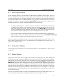
Part II - OHAP Application Framework
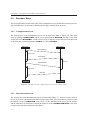
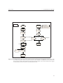
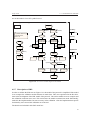
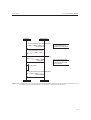
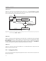
The OHAP concept is divided into two parts, namely the OHAP Application Framework (OAF) and
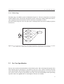
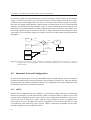
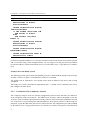
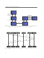
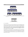
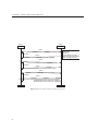
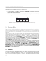
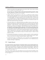
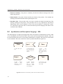
the OHAP Protocol Stack (OPS) as shown in Figure 1.1. By dividing the development into two
smaller parts the scope of each part becomes smaller and easier to handle. In order to define the
separation point where software is OAF and OPS the OSI model is used. From layer 6 and down the
software is defined to be a part of the OPS. Hence applications and their protocols are parts of the
OAF. Since the requirements are developed from a use case driven method, they will mainly concern
the application area visible to the actor in the use case and not directly the protocol. Hence after
designing the OAF more requirements will be set forth to the OPS as shown in Figure 1.1.
Figure 1.1: This figure shows where the requirements to the OHAP Protocol Stack and the OHAP Application Framework
originates.
In chapter 4 the different technologies that is used in an home automation framework is analyzed. The
two most important issues, Automatic network configuration and Service Discovery are then given a
more thorough analysis in chapter 5 and 6.
16
Group 1032i
1.2.3
1.2. READING GUIDE
Part III - OHAP Protocol Stack
Chapter 7 starts by defining the addressing scheme, a proxy concept and an analysis of different
routing protocols. Chapter 8 deals with the routing aspect of the OHAP stack. Chapter 9 is about the
combined network and transportation layer.
1.2.4
Part IV - Prototype
The prototype part is about the developed hardware and software in Chapter 11 and Chapter 12
respectfully.
1.2.5
Part V - Project Closure
The project closure starts with the results obtained in this thesis and end with a conclusion concerning
the state of the thesis.
1.2.6
Part VI - Appendix
The first appendix provides insight into some different communication technologies. The second
appendix deals with the notation used in the thesis to create diagrams.
1.2.7
Reading Paths
One path through this thesis is to read it from the first to the last page. If a shorter version is desired,
Chapters 2, 4, 7 and 13 is recommended reading reading since this will introduce the OHAP concept,
introduce the OAF and OPS and round of with the project closure.
17
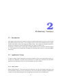
2
Preliminary Analysis
2.1
Introduction
This chapter will provide some example scenarios of OHAP enabled devices to give an idea of what
the OHAP concept can be used for. The examples will be used to derive different classes of applications which will be used in the design the OHAP system. This refrains the solutions found to be
specific for a single device and not broad enough to fit a range of similar devices.
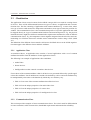
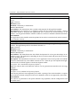
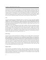
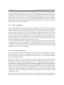
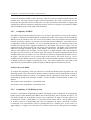
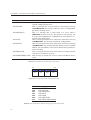
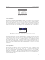
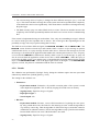
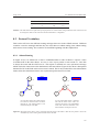
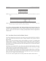
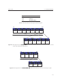
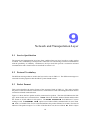
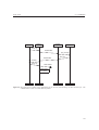
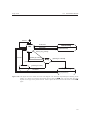
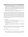
To illustrate a scenario where a person buys a standard OHAP device in a market is shown in Figure
2.1. This emphasizes the concept that everything can interconnect due to the use of the same OHAP
stack [Esk].
2.2
Application Visions
In order to design a home automation system that would be a success, the requirements for the system has to be identified. To identify the requirements for a broad range of both present and future
application, the following visions for a home automation system is enlisted.
2.2.1
Door Locks
When leaving the house a click on the house-key will lock every door and window in the house and
warn if the house cannot be secured. The house-key offer secure and non re-playable communication
in order to avoid compromising the house if anybody tries to listen to the communication.
19
CHAPTER 2. PRELIMINARY ANALYSIS
(a) The OHAP logo.
(b) Mr. Hansen, a Saturday morning in the building market.
(c) It is easy for Mr.
Hansen to buy and install Home Automation
devices.
(d) The OHAP brand
gives safety. Mr. Hansen
knows that the product
will cooperate with his
existing system without
any problems.
(e) Many categories of
devices are part of the
OHAP brand.
(f) All OHAP certified
products coexists and
can cooperate,
even
from different manufacturers.
The customers
investment is protected.
(g) The open standard
ensures competition and
continual development.
(h) It is easy to install,
and configure the devices
in the home.
(i) Setup can be done easily and intuitive via a simple user interface on e.g.
a PC.
Figure 2.1: The OHAP concept. Illustration of a scenario where a OHAP product is bought and installed.
20
Group 1032i
2.2.2
2.2. APPLICATION VISIONS
Sensor Readings
Today, regularly checks are made by power and heating supply companies, these checks could be
made obsolete by installing a sensor capable of reading the current status and using the home automation system to transmit the measurements directly to the company. This will save the trip to each
house and create the possibility of continual usage observation, which could help to indicate abnormal usage. For instance, if the family vacates and the water pipes break, a water usage is registered
which triggers the indoor alarm. If this is not responded to within a short period of time, the house
system will try to fetch help.
2.2.3
Refrigerator Intelligence
The refrigerator can become a central point of control in the kitchen when combining it with a display
and a input device, since it is placed central and is always powered on. If the refrigerator is aware of
its contents, it should be possible to choose a dinner on the panel. If anything is missing, the items
will be ordered via the Internet. Knowing the dinner and the desired eating time, the oven can be
started at the correct time. Also the expire date of the different items can be checked in order to
suggest diners to minimize the amount of food that spoils.
2.2.4
Video Surveillance
Several video streams might be monitored where there are a display, this could be the television or
even the refrigerator if needed. A stream might originate from the front door such that when the door
bell rings the TV automatically switches over to show who it is, hereafter the bottom on the remote
is pushed which unlocks the door. Another stream could be a baby alarm which also could be shown
or listened to on the television instead of baby alarm receiver.
2.2.5
Intelligent Light Control
Home automation could be used in the area of lightening control, where the lights in a building
operates intelligent. The lights adapts to their environment by getting inputs from light and movement
sensors, remote controls or voice recognition devices etc. Examples of applications could be: The
light turns off in a room if no persons are in it. The lights turn off when people leave the building or
if the daylight is bright enough to provide good lighting. In a residential application the lights in the
living room could be dimmed if the TV is turned on, or in the night the lights along the path to the
bathroom could be turned on by pressing a button in the bedroom.
2.2.6
Voice Control
Voice control of a home automation system could be a desirable application. Rooms could be
equipped with microphones, loudspeakers and voice recognition modules enabling persons to give
commands to the home automation system. The use could be to turn on/off light, air conditioning,
music etc. The system could also be used as a intercom for communication with other people in the
building or even extended to be used with the ordinary telephony system.
21
CHAPTER 2. PRELIMINARY ANALYSIS
2.2.7
Person Surveillance
A building equipped with RFID [Inc03] scanners in doors and important areas would allow a security
or surveillance system to keep track of people moving around in the building, if they wear a RFID
tag. The application could be to use RFID as access cards to restricted areas in office environments,
industries or in the health care sector to monitor the movement of elderly or disabled people at home.
The same tags could be used in residential applications for localizing people in rooms and e.g. set
favorite temperature, play favorite music or transfer phone calls to the room.
2.2.8
Calendar Synchronization
When a calendar appointment arrives via the Internet, an icon can appear on the TV, the refrigerator,
the dash board of the car or anywhere else containing an OHAP enabled interface. If an early morning
appointment is accepted, a message is sent to adjust the clock radio, the coffee machine, the heating
system and the auto pre-heating in the car. And to ensure that the appointment is reached in time,
the clock radio will be monitored by other devices checking for liveliness. In case of silence another
alarm will sound, this could be from any device capable of making a warning sound indicating that a
device is failing in the system.
2.2.9
Internet Gateway
A home automation system could be connected to an Internet gateway to either remote control the
system from outside or to let the home automation appliances access services on the Internet. The
services provided for the home appliances could be: automatic software update of devices from
manufactures servers, getting weather forecasts to be used in climate control, getting sports results
etc. The devices could also subscribe on push services where the service provider could send a
message to the home automation system if e.g. a natural disaster is approaching the house.
2.2.10
Intelligent Toys
Intelligent toys could take benefit of a home automation system in a house by interacting wireless
with the sensors and actuators in the house, using Internet gateways for e.g. submitting high scores
and downloading new features. This would give kids more interactive play and maybe increased
enjoyment. This imposes concerns as to what a OHAP device can access due to risks imposed during
play.
2.2.11
Heating, Ventilation and Air Conditioning (HVAC)
The HVAC systems in a building are often controlled independently where cooperation between the
different systems is a actually a desired feature. A home automation system could interconnect the
HVAC systems to achieve this. E.g. when the temperature in a room is set to rise, the heating system
could tell the air conditioning and the ventilation system to stop cooling and thereby achieving the
goal in a more energy efficient way. The HVAC systems could also be connected to other systems like
22
Group 1032i
2.2. APPLICATION VISIONS
smoke detectors, and in the case of a fire, the ventilation system could stop pumping fresh oxygen
into the fire, slowing the fire spreading.
2.2.12
OHAP Enabling
The possibility for old non OHAP devices to join the OHAP network would be a useful feature. The
old devices could join the network with the use of OHAP enablers that e.g. could power a relay in
light switches or power sockets without the lights or equipment in the power sockets needs to be
OHAP enabled from the beginning.
2.2.13
Overview
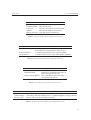
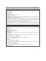
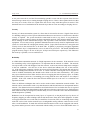
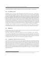
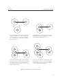
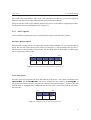
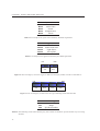
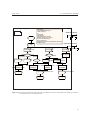
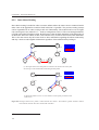
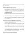
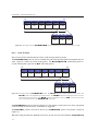
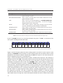
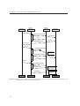
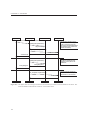
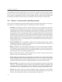
The application visions can be transferred to an residential home, as seen on Figure 2.2. The picture
is a floor plan of an house and shows the different situations where the OHAP devices are used.
Figure 2.2: This figure shows a residential home where different applications of the OHAP system are used.
23
CHAPTER 2. PRELIMINARY ANALYSIS
2.3 Classification
The application visions created a context for the OHAP concept, this is now used for creating classes
of devices. There will be differentiated between two types of classes, an application and a communication class. The first consisting of applications with common attributes e.g. a sensor class, where
one type of sensor could measure the temperature and another sensor type measure the position of a
window. The communication class is the communication profile of a specific application and could
be mapped directly to a type of communication hardware and associated protocol. E.g. the previous
mentioned sensors might have different communication requirements and therefor reside in different
communication classes. E.g. the temperature sensor might be integrated into the television and communicating over LIN Bus whereas the window sensor communicates wireless using a rfPIC (Table
A.1).
The definition of the different classes must be valid across all OHAP devices so the OHAP organization must approve the different classes and their attributes.
2.3.1
Application Class
As mentioned above, an application class consists of several applications with a set of common
attributes that differs from the attributes of other application classes.
The following is an example of applications class candidates:
• Audio/Video
• Sensor Devices
• Intelligent Devices that controls or monitors other devices
First a subset of the common attributes valid for all devices are presented followed by specific application class attributes. Not all attributes are needed to be defined by a device and some attributes may
be manipulated by other units so the duration by which they are valid may vary.
• Table 2.1 lists some of the common attributes that all devices have.
• Table 2.2 lists the unique properties of an audio/video class.
• Table 2.3 lists the unique properties of a sensor class.
• Table 2.4 lists the unique properties of a intelligent device class.
2.3.2
Communication Class
This section provides examples of some communication classes. The criteria used for differentiation
are time constraints, traffic characteristics, bandwidth requirements and transmission reliability.
24
Group 1032i
2.3. CLASSIFICATION
Attributes:
Manufacturer
Production Data
Power on
Address
Battery Powered
Description:
The name of the manufacturer
The creation time
The time when the device last booted
The network address of the device
Does this device use batteries
Table 2.1: Common attributes which are defined for all devices.
Attributes:
Transmission Codecs
Video resolution
Audio quality
Description:
A comma separated list of all codecs
that could be used to transmit to other devices
A comma separated list of all video resolutions
A comma separated list of the audio quality supported
Table 2.2: This table shows the attributes of the audio/video class.
Attributes:
Sampling rate
Alarm threshold
Alarm receiver address
Description:
The sampling rate of the device
If the device supersedes this value, an
alarm message must be sent.
This is the address where the alarm
message must be sent to
Table 2.3: This table shows the attributes of the sensor class.
Attributes:
Control domain
Control strategy
Security level
Description:
Tells what kind of devices the intelligent device can control
The strategy that the controller uses e.g. high throughput or energy efficient
The security level the controller can access
Table 2.4: This table shows the attributes of the intelligent device class.
25
CHAPTER 2. PRELIMINARY ANALYSIS
• The time constraints of an application is one of three priority levels. High priority signifies
the highest priority messages in the system, where for each tenths of a second the message is
delayed, a situation worsens. Middle priority is i.e. a user creating a stimuli to a system and
awaits a response, this type of message is best served within a few seconds depending on the
application. Low priority signifies the messages that should be transferred within a few minutes
to a few hours of creation, this could be measurement data with long periods of time without
variation.
• The traffic characteristics used are periodic, aperiodic and sporadic. These characterizes the
transmission periods, i.e. a phone call is considered aperiodic even though the call sends packets periodically when the call is established.
• The bandwidth class can be divided up into as many categories as there are available transmission rates. Instead the bandwidth requirement of a device has to examined and compared
to that of the offered bandwidth of the communication technology. Some classes could still
be defined which rely on preferred communication technology recommended by OHAP. Some
example limits for bandwidth classes could be 300 bps for the lowest devices, 9 kbps for voice
etc.
• The media (wired/wireless) attribute covers the expected communication link used in the application.
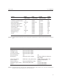
In Table 2.5 each vision is described with regards to the above mentioned properties. Some visions
are specified as belonging to several different property classes, i.e. sensor readings belongs to several
categories. This is because of the wide variety of sensors that could exist within a single product
group ranging from the simplest temperature sensors broadcasting measurements every 5 minutes
without the capability to receive any signal to the advanced temperature sensor with configurable
threshold values for transmitting its temperature and variable period intervals etc.
When grouping the applications with the same properties from Table 2.5 and compare these with
Table A.1 and Table A.2, Table 2.6 is derived. The table shows some of the possible communication
hardware for the different visions.
2.4 Summary
In the beginning of this chapter some application visions was provided that were classified into application and communication classes. The application classes are candidates for consumer product
categories of devices with the same properties. hence, a manufacturer has to produce a device for a
given class. The application classes should be the basis of the further work instead of finding solution
to specific applications. This make the work more general and the possibility of reuse of components
is increased in different applications.
The communication classes provides an example of how the manufacturer can select communication
hardware for a given application. This makes the design process easier for manufacturers who does
not have communiction hardware experience.
Based on this chapter, a requirement specification will be made in the next chapter.
26
Group 1032i
2.4. SUMMARY
Vision:
Door Locks
Calendar Synchronization
Sensor Readings
Refrigerator Intelligence
Video Surveillance
Intelligent Light Control
Voice Control
Person Surveillance
Internet Gateway
Intelligent Toys
HVAC
Bandwidth (kbps):
< 2.4
< 10
Depends
< 10
64
< 2.4
< 10
< 10
Depends
< 10
<5
Time
Constraints:
middle
middle
middle/low
middle
middle
middle
middle
middle
middle
middle
middle
Traffic
Characteristic:
aperiodic
aperiodic
all
aperiodic
aperiodic
aperiodic
aperiodic
aperiodic
aperiodic
aperiodic
aperiodic/
periodic
Media
Type:
Yes
Yes
Both
Both
Both
Both
No
Yes
Both
Yes
No
Table 2.5: This table shows the different visions with regards to bandwidth, time contraints, traffic characteristic and media
type.
Vision:
Door Lock
Intelligent Toys
Calendar Synch.
Person Surveillance
Sensor Readings
Refrigerator
Wireless
Bluetooth,rfPIC,ZigBee
Bluetooth,rfPIC,ZigBee
Bluetooth,rfPIC,ZigBee
Bluetooth,rfPIC,ZigBee
All
Bluetooth, rfPIC, ZigBee
Video Surveillance
Voice Control
Internet Gateway
Intelligent Light Control
HVAC
IEEE 802.11a/b/g, Bluetooth,
Bluetooth,IEEE 802.11a/b/g
Bluetooth,ZigBee,rfPIC
Wired
All
LIN Bus, IEEE1394, Ethernet,
EIB,CEBUS
CEBus, Ethernet, IEEE 1394
LIN Bus, EIB,CEBUS
Ethernet
LIN Bus,EIB,CEBus
LIN Bus,EIB,CEBus
Table 2.6: This table shows the visions and the communication hardware that could be used. The listed communication
hardware for the Internet Gateway is on the customer side.
27
3
Requirement Specification
This chapter will set forth requirements to the OHAP concept. The requirements are obtained from
the application visions described earlier, both from a manufacturers point of view and also the every
day usage scenarios. The requirements are described using the use cases driven method described in
Kravspecifikation vha. Use Case teknikken [DTI96]. Furthermore general and formal requirements
are made that defines the requirements from a system perspective.
3.1
System Description
The OHAP system is a general purpose home automation system that consists of OHAP enabled
devices such as sensors, actuators, displays etc. The OHAP system is a concept that is created by
connecting OHAP enabled devices together, letting them communicate, cooperate and perform actions according to stimuli and predefined behaviors.
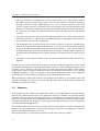
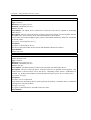
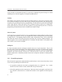
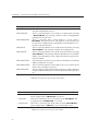
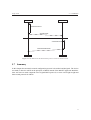
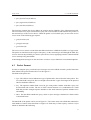
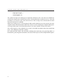
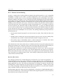
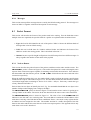
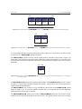
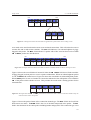
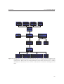
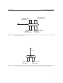
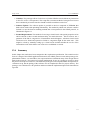
The actors in the OHAP system are consumers, technicians and manufacturers. This is illustrated in
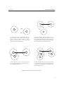
Figure 3.1
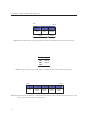
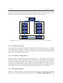
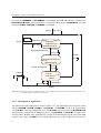
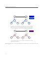
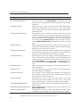
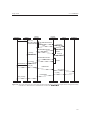
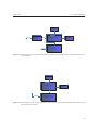
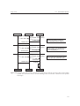
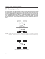
The typical use of an OHAP system is illustrated in Figure 3.2. The OHAP system is represented by
OHAP enabled devices such as sensors, actuators, intelligent devices and displays. The user interacts
with the system via an interface, illustrated as an OHAP display. Interaction between the different
OHAP devices is seen as the two-way arrows between the devices.
3.2
System Functionality
The use of an OHAP system can be described in three phases:
• At the manufacturer where the devices are developed and produced.
29
CHAPTER 3. REQUIREMENT SPECIFICATION
Manufacturer
OHAP System
Consumer
Technician
OHAP Device
Figure 3.1: Actor-context diagram of the OHAP system
OHAP
Sensor
OHAP
Intelligent
Unit
OHAP
Actuator
OHAP
Display
User
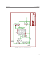
Figure 3.2: Illustration of a typical OHAP system where the actuator is set up by the intelligent device. The actuator will
act upon the impulses received from the OHAP sensor
30
Group 1032i
3.2. SYSTEM FUNCTIONALITY
• The device setup and service phase, where the OHAP device is inserted into the network.
• The phase where the OHAP network is running and used on a daily basis.
To provide an overview of the system functionality use case diagrams [DTI96] are made for each of
the above mentioned phases.
3.2.1
User Profiles
This section will describe the three different users of the system.
The daily users of the system is consumers that is not expected to have a great knowledge of communication technology and computers. The consumers use the system in a non technical way, and is not
expected to make advanced technical configurations. The user is able to change batteries, insert new
devices and remove these again. Also simple device setup may be performed by the daily user.
The service technician has a great knowledge of communication technology and computers. The
technician configures and performs network management on the system if needed. This should only
be needed when the system configuration is advanced and has special requirements.
The manufacturer might have some knowledge in communication technology and computers. He
integrates the OHAP concept with his products in order to bring increased value to them.
3.2.2
Manufacturer Setup
The OHAP concept is not only intended for companies with experience in embedded systems and
networks. Hence an OHAP development kit that can be used by companies with little experience in
embedded programming is needed. The development kit could be developed using an open source
model where each manufacturer uses the common code base and commits enhancements they need.
An incitement for committing their enhancements could be a license agreement for using the common
code base which requires that changes must be made public.
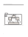
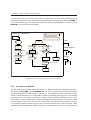
At the manufacturer, the system profile is defined and implemented in the OHAP device using this
tool, see Figure 3.3. The system profile is a combination of an application and communication class
as described in section 2.3. The participation level in the OHAP network is also specified with the
development kit. This is properties such as routing capability, intelligence, control etc.
If companies choose to develop the protocols themselves, it is still possible to get the product OHAP
certified. The certification test should be applied to all devices regardless of code base, checking that
they conform to the OHAP protocols.
Each manufacturer has to create one or more specific applications per device, which need to be
integrated with the rest of the toolkit.
3.2.3
Device Setup and Service
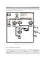
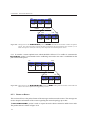
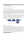
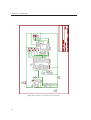
As Figure 3.4 shows one of the functionalities in the OHAP system setup phase is to add devices to
the network. After the device has been turned on, the device discovery or an announcement phase is
31
CHAPTER 3. REQUIREMENT SPECIFICATION
Figure 3.3: Use case diagram of the manufacturer setup process. This example shows the definition of a device using the
development kit. Also the definition of an application and communication profile is needed. Last conformance
test must be executed in order to certify the product.
initiated by the new device. If the device finds the OHAP network, it is possible to setup the device
via the configuration interface. The configuration could be done from a PC, phone or directly on the
device itself. The device may have several setup levels ranging from very complex with threshold
triggers for sending out events and controlling devices, to the fully automatic with no user interaction.
When a device is removed or powered off by the user the network reconfigures itself.
If problems exist with the network, it should be possible for a skilled person to do network management. This person can fine tune parameters, connections and security options that may help to solve
the problems. All of this should also be possible for normal users but a bit of knowledge concerning
networks is assumed.
Figure 3.4: Use case diagram of device setup and service. The service check may also be performed by a user, but requires
more knowledge to perform the network management configurations possible.
32
Group 1032i
3.2.4
3.3. USE CASE SPECIFICATION
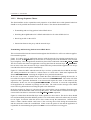
Daily Usage
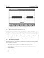
The daily usage of an OHAP system is illustrated in Figure 3.5. The user can perform several tasks
with the OHAP system. Stream video through the network, read sensor readings online from a device,
view a log history and current status of a device and issue a command to a device.
All of these daily usage use cases uses query device which performs the concrete sending of packets
to the device.
Uses
Data streaming
Uses
Query device
Sensor
reading
Uses
Status view
Uses
User
Perform action
Figure 3.5: Use case diagram of daily usage. This illustrate the different connection types there could be to an OHAP
device. Status view is mainly a history log while perform action might require action immediately.
3.3
Use Case Specification
The use cases describe the functionalities of the OHAP system. Since a thorough description of the
entire OHAP system would require a vast number of use cases, only a subset is described focusing
on key functionalities instead which might be be implemented in the prototype. Even more, the use
cases can be used as accept test specifications since they state what should happen when performing
a specific action. See appendix B.1 for a description of the use case method.
33
CHAPTER 3. REQUIREMENT SPECIFICATION
Create Device Application
Introduction: This use case describes the manufacturer creating the application for an OHAP
device.
Type: Concrete
Relations: None.
Initiation: Initiated by a manufacturer.
Actors: Manufacturer.
Precondition: The manufacturer has a product with potential for being OHAP enabled.
Description:First an interface for a computer system must be found on the product. Then an
application should be designed and implemented able to perform the desired functions of the
product. Last all general attributes which are define for all device should be identified and stated.
Postcondition:
The application which should control the product has now been created and only needs connectivity to function correctly.
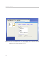
Define Application Profile
Introduction: This use case describes the manufacturer defining the application profile of the
product. The application profile is described in Section 2.3.
Type: Concrete
Relations: None.
Initiation: Initiated by a manufacturer.
Actors: Manufacturer.
Precondition: The manufacturer has the OHAP development kit or has great knowledge in embedded systems. The application controlling the device has been made and just needs an environment to be deployed in.
Description: The manufacturer locates the correct application class for the product and whether
the device should offer any extra OHAP network services. Then the previous implemented application needs to be linked together with the development toolkit.
[Exception: Not a standard development platform .]
When the software has been linked the software can be generated and transferred to the target
platform.
Exceptions:
Exception: Not a standard development platform
If the chosen platform is not supported by the toolkit, a porting of the needed modules is required.
This could also include writing device driver for hardware which is not supported by the toolkit.
Postcondition:
The software is generated for the specific hardware target platform, and the configuration saved
for further reuse.
34
Group 1032i
3.3. USE CASE SPECIFICATION
Define Communication Profile
Introduction:This use case describes the manufacturer defining the communication profile of a
new OHAP device.
Type: Concrete
Relations: None
Initiation: Initiated by a manufacturer.
Actors: Manufacturer.
Precondition:The manufacturer has the OHAP development kit and the rest of the software constituting the new OHAP enabled device.
Description:The manufacturer of a new OHAP device needs to know which communication hardware the device must support. I.e. when creating a device capable of Bluetooth and power line
communication, these modules must be selected. When the communication modules have been
chosen and the target platform specified, the software can be generated.
Postcondition:The software is generated for the specific hardware target platform, and the configuration saved for further reuse. The product is OHAP enabled and could be connected to other
devices.
Device Status View
Introduction: This use case describes how a device can be monitored and its network statistics
viewed.
Type: Concrete.
Relations: Uses Query Device.
Initiation: Initiated by the user.
Actors: The user.
Precondition:A working OHAP device connected to a device containing an interface from where
the user works.
Description: The user chooses a device of interest and a list of status parameters such as battery
status, detected errors etc. will be shown.
[Exception: OHAP device malfunctions.]
The user can update the information by issuing an update command.
[Exception: Cannot find the device]
Exceptions:
Exception: OHAP device malfunctions.
If any failures are detected the device can be replaced, checked by a controller unit or a technician
called upon to solve the problem.
Exception: Cannot find the device
The device cannot be found on the network and should be checked for failures.
Postcondition: None
35
CHAPTER 3. REQUIREMENT SPECIFICATION
Manual Sensor Reading
Introduction: To read the sensor values of a device.
Type: Concrete.
Relations: Uses Query Device.
Initiation: Initiated by the user.
Actors: The user.
Precondition: An OHAP device connected in a network with a device capable of monitoring
other devices.
Description: The user selects the device of interest and a list of values is shown together with the
last update time. Also a history of the latest measurements can be shown.
If new values are needed an update request can be issued which should force the device to transmit
its current values.
[Exception: Cannot find the device]
Exceptions:
Exception: Cannot find the device
The device cannot be found on the network and should be checked for failures.
Postcondition:
Sensors are read.
Perform Action
Introduction: This use case describes how to perform an action with an OHAP device from
another network node.
Type: Concrete
Relations: Uses Query Device.
Initiation: Initiated by the user.
Actors: The user.
Precondition: An OHAP actuator connected in a network with the monitor device.
Description: The user selects the device of interest and a list of possible actions appears. The
needed action is selected and is sent to the device. Depending on the action a confirmation is
returned, e.g. all doors and windows are locked and secured [Exception: Device malfunction]
[Exception: No reply]
Exceptions:
Exception: Device malfunction
If any failures are detected the device can be replaced, checked by a controller unit or a technician
called upon to solve the problem.
Exception: No reply
Try again or reboot the device and add to unit once more.
Postcondition:
36
Group 1032i
3.3. USE CASE SPECIFICATION
Data Streaming
Introduction: Getting an audio or a video stream from a multimedia device.
Type: Concrete.
Relations: Uses Query Device.
Initiation: Initiated by the user.
Actors: The user.
Precondition: The user selects the device of interest capable of transmitting multimedia streams.
Description: The user selects the multimedia device and the kind of stream wanted. The stream
will appear on the interface device that the user utilizes, either in the form of audio, video or both.
[Exception: Not enough bandwidth]
The stream continues until the user aborts the stream or the connection is disrupted.
Exceptions:
Exception: Not enough bandwidth:
If the intermediate nodes does not support the required bandwidth, or refuses because of a power
saving mode then the stream cannot be created.
Postcondition:
Query Device
Introduction: This will send a query to a device in order to issue a command, network management operation or a request for data.
Type:Abstract.
Relations: None
Initiation: Initiated by one of the initiating Use Cases.
Actors: See the concrete use case.
Precondition:
Description: The query device use case performs the actual request on the network on the behalf
of other use cases. Bringing together the functionality that communicates with other devices
simplifies the further design while avoiding redundancy of functionality. The query device receives
a message and tries to locate the recipient device or devices and transmits it to this unit.
[Exception: Cannot find the device]
The response from the unit is delivered to the creator of the message.
Exceptions:
Exception: Cannot find the device:
The device cannot be found on the network and should be checked for failures.
Postcondition:
37
CHAPTER 3. REQUIREMENT SPECIFICATION
Add unit
Introduction: This use case handles the operation of adding a unit to an OHAP system.
Type: Concrete
Relations: Uses Device discovery.
Initiation: Initiated by the user.
Actors: The user.
Precondition:
Description:
To add a new OHAP unit to the OHAP system the user must take the new OHAP device into the
range of the existing wireless OHAP network or plug it into the wired network. The new device
now discovers its neighbors and becomes a part of the network topology.
[Exception: Cannot find any other OHAP devices]
The new OHAP device is now ready to be authorized in order to communicate on the network.
[Exception: Authorization failed]
The device is authorized and present on the OHAP network.
Exceptions:
Exception: Cannot find any other OHAP devices:
The user is warned by sound/light or a message that it was not possible to find other devices. User
can move closer to a wireless OHAP device to get better contact or use another wired plug in the
building.
Exception: Authorization failed:
The user is warned by sound/light or a message that the authorization failed, the user can try again.
Postcondition:
The new device is now ready to setup.
Remove Unit
Introduction: This use case describes the removal of an OHAP device from the network
Type: Concrete
Relations: None
Initiation: Initiated by the user.
Actors: The user.
Precondition: None
Description:
The OHAP device is removed from the network by either powering it down, removing it from its
physical location or by excluding it from a network management program.
Exceptions:
Postcondition:
The device is no longer present on the OHAP network.
38
Group 1032i
3.3. USE CASE SPECIFICATION
Setup
Introduction: This use case describes the setup of an OHAP device.
Type: Concrete
Relations: Uses Selection of device.
Initiation: Initiated by the user.
Actors: The user.
Precondition: The OHAP device is authorized on the network.
Description:
After selection of the device (see abstract use case) the setup on the selected device can be made.
[Exception: Selection of device failed]
In the setup it is possible to enter several parameters according to the device. The setup can be
saved.
[Exception: Setup not saved]
Setup is finished.
Exceptions:
Selection of device failed: Add the device to the network again and try to setup again.
Setup not saved: Try again.
Postcondition:
The device is configured and ready to perform its tasks.
Service Check
Introduction: This use case describes a service check of an OHAP device
Type: Concrete
Relations: None
Initiation: Initiated by a service technician.
Actors: The service technician.
Precondition: An OHAP network is present
Description:
The OHAP system can have a service check by a service technician. It is possible to perform network management and fine tune the system since the technician has greater knowledge concerning
OHAP systems.
Exceptions:
Postcondition:
The system is optimized towards either better performance, connection redundancy etc.
39
CHAPTER 3. REQUIREMENT SPECIFICATION
Device Discover
Introduction: This use case describes how device discovery is performed.
Type: Abstract
Relations: None
Initiation: Initiated by one of the initiating use cases.
Actors: See the concrete use case.
Precondition: An OHAP network is present
Description:
The device discovery is an internal process in an OHAP device. When a OHAP device is inserted
into a network it starts the device discovery. During the device discovery the device learns about
its neighbors and should be shown on an interface that a new unit has been found.
Exceptions:
Postcondition:
The device is known to the OHAP network and is ready to participate.
Selection of Device
Introduction: This use case describes how selection of device is performed.
Type: Concrete
Relations: None
Initiation: Initiated by one of the initiating use cases.
Actors: See the concrete use case.
Precondition: An OHAP network is present
Description:
The selection of device is performed by a initiating use case, and covers the way a user selects a
device to further use. The device selection is made on a display of some kind where all the units
in the network are present. The user can then simply select the device and perform the needed
actions.
Exceptions:
Postcondition:
A device is selected for further use.
3.4 System Requirements
By extracting the requirements set forth by the application visions described earlier, the following
general system and formal requirements have been identified. By having many visions and requirements, a better foundation for developing a versatile and optimized protocol stack exists.
3.4.1
General requirements
This will list the general requirements to the OHAP system. Often, the requirements are contradicting,
making a solution a trade off between two requirements.
40
Group 1032i
3.4. SYSTEM REQUIREMENTS
Scalability
The OHAP system has several areas where scalability is of importance.
• The OHAP protocols should be light-weight in order to ensure that the developed protocol
stack could be implemented on small and cheap 8 bit microprocessors. Still, it should provide
the functionality needed to carry complex protocols that are needed by larger applications.
• The address space should not limit a household from purchasing new devices, where the number of devices being in the magnitude of thousands.
• The bandwidth should range from a few bytes from a sensor reading each minute to a viewable
TV signal with sound streaming from a front door.
• Low powered units should be allowed to only appear on the network when they have data to
transmit and others should be constantly transmitting data.
Internet Enabling
There are several applications where OHAP devices could use the Internet to seek information or
update software etc. The web enabling of some devices should not impose such a complex network
structure, that the smallest devices needs to be upgraded with a larger software footprint or more
expensive hardware. Three possibilities is considered as a viable solution for Internet enabling OHAP
devices:
• An Internet gateway placed between the OHAP network and the Internet. This translates between an OHAP protocol designed specifically to send request back and forth to the gateway
which executes these. The requests should be encapsulated in the normal OHAP traffic. While
this does not increase the complexity of the devices not utilizing the Internet it forces the web
enabled devices to learn the Gateway address and the protocol for accessing the Internet.
• Letting the entire OHAP network function on IP and provide a connection to the Internet. The
OHAP network could still be protected with a firewall, router etc. This requires that all devices
internally use IP but has less requirements for the connection to the Internet, e.g. no gateway
is needed.
• Letting the devices that require an Internet connection use IP and tunnel these packages in
the OHAP protocol. This does not impose an overhead for device not participating while still
letting all IP applications function.
Range
As the system is intended to be deployed in a building such as a residential house, the system should
cover the whole area. This does not mean that a technology has to have a range that covers the
building. Mechanisms such as repeaters or multi hop routing between several devices can be used to
extend the coverage of the network.
41
CHAPTER 3. REQUIREMENT SPECIFICATION
To increase the range of a single device there are several influencing factors. The power of the transmitted signal is a factor that has a great influence on the range, more power means longer range. The
power can however not be increased unlimited because national along with international regulations
only permit certain transmit power levels of RF equipment according to the frequency band. The
antenna sensitivity is also important, a more sensitive antenna can detect a weaker signal at a longer
range. The frequency band is also of importance, a lower frequency has a longer range than a higher,
due to the signals attenuation through air and obstacles which is higher for a higher frequency.
Cost
To get the technology deployed throughout devices in a home, the cost per node and installation
should be kept at a minimum. Low cost will be a key factor if the OHAP technology should be
widely used. A low price component as a light switch must not increase significantly in price just
because it has a micro-controller embedded and can communicate with other devices. The price for a
technology that should be embedded in such cheap components as light switches must be in the few
dollar range or lower [Esk03].
To get the low price, the technology must be simple to produce and it must be produced in large
quantities. The smaller and simpler controller that can be used to host the protocol the cheaper
the end product becomes, hence the protocol must be small and efficient. Another issue is that the
protocol should be free and available in open source format in order for the manufactures to avoid
paying royalties for use of proprietary protocols. When all devices use the same protocol, this will
in itself create value for the customers. It should also be avoided to use a radio band that requires a
expensive operating license as this would increase the cost.
Power usage
The power usage of a home automation device should be as low as possible. This is to ensure that the
lifetime of battery driven wireless devices are so high that the new technology is not seen inconvenient, and battery has to be changed every week. The lifetime of battery driven devices should be in
the range of months to years like a normal smoke sensor. To achieve this the duty cycle of the device
can be reduced by putting the device to sleep and only waking it when data has to be transmitted or
its services is needed. The radio transmission power can also be reduced to lower power usage but
with a lower range as a consequence. Devices that communicate over wire should not necessarily be
battery driven since power can be feed either by the communication cable or by power lines. Hence
devices on the wired network does not have the same concerns about power usage, and can be used
as routers and backbone nodes that are always awake.
Response Time
The response time vary depending on the device and its functionality. A temperature sensor may only
need to send in readings once every 5-10 minutes with no requirements to the delay of the message,
whereas the smoke detector must get its message through within 3 seconds in case of a fire. [Sta03]
[Ins96] A method for guaranteeing a worst case delay is to use deterministic network calculus and
model each node after worst case scenarios.
42
Group 1032i
3.4. SYSTEM REQUIREMENTS
A low power network is not ideal for transmitting sporadic events with low response time since the
alarm message cannot rely on routing through sleeping devices. Hence a direct path with devices that
are alway on or in the worst case a path where the devices sleep with short period is needed. This
demands some sort of mechanism in the network layer that can route according to sleeping devices.
Security
Security of a home automation system is a factor that is relevant for the users. Signals from devices
in a building could give a lot of private information about users and access to critical areas, therefore
security is required. The system should be constructed in such a way, that it is not possible for
intruders to remote control or destroy the home automation network. This includes sniffing of packets
and re-sending of these old/altered messages, and if possible avoid interference from other radio
equipment. To overcome security problems authentication and security must be implemented in the
system in a scale that CPU and program memory allows. Topics like trusted devices, encryption and
security levels in the network have to be dealt with. In [PB01] a proprietary encryption algorithm
with symmetric keys is implemented to run on 8 and 16 bit processors. The RAM, EEPROM and
program memory usage is as low as 28 bytes, 28 bytes and 1628 bytes respectively. This illustrates
that security is possible, even on small devices.
Reliability
A reliable home automation network is of high importance for the customers. If the network is used
for controlling safety critical applications it is important that the network is reliable. The network
can expect that a node will disappear from the network, so the network must adapt and reconfigure
to the new conditions. Also the loss of one device should not influence the rest of the network,
e.g. if the refrigerator computer is broke, the toaster will still function. This argues that each device
should be intelligent and function on its own. A central controller can bring the devices together in
order to combine functionality but should not be relied on for the entire functionality. The system
may expect interference from other wireless devices occupying the same frequency space. A reliable
home automation system can, if something goes wrong, find the error and maybe fix it or adapt if
possible. If the error cannot be fixed the network should report it so the user or a technician can
repair the network.
There are different techniques that can be used to make a home automation network reliable. The
network can be constructed in such a way that robustness and fault tolerance are incorporated into the
network. The distinction between robustness and fault tolerance lies in whether the error is expected
or unexpected. This means that robustness deals with errors that are expected to occur. Fault tolerance
deals with errors that are unexpected, and the ability to recover from the errors and still maintain the
intended operation. [IZM03]
Robustness can be incorporated on many layers of a protocol, on the physical layer by the use of
frequency hopping or other techniques that avoids interference from other radio equipment. In order
to keep persistent data over a radio link, Forward Error Correction (FEC) or a hamming scheme along
with CRC can be used. On the network layer, reconfigurable routing schemes can be used to recover
after a node breakdown. To make the network fault tolerant the nodes can be equipped with watchdog timers and the protocol can be constructed with the ability to recover from undesirable states. It
43
CHAPTER 3. REQUIREMENT SPECIFICATION
is also possible to avoid undesired states in a protocol by validating the protocol design in a model
validating tool as UPPAAL [upp03] or Telelogic Tau SDT [tel03a].
Usability
The usability is not required to be the same between different devices. Some devices will only require
to be switched on and they will work, others may be configured with parameters and a third type may
set up the users personal preferences by programming. To allow this, the system must be designed
with a "Plug and Play" ability that allows a device joining the network with no user configuration.
On the other hand, the system must also allow products to be programmed by the user, so a kind of
programming environment must also be available in the OHAP concept.
Software Update
As new devices are created some devices may get outdated and a software update is needed. Also in
case of bugs in the firmware, an easy way to update the software will improve the perceived quality
of OHAP devices. The updating method could be either automatically where a device downloads
and installs the firmware itself using the Internet and other may need to be flashed manually. The
software update is not a crucial requirement but if a method exists that allows it, the quality of the
entire OHAP system would seem higher.
Intelligence
In a home automation network, intelligent controller devices are of great importance. They are the
glue that connects all the functionality of the different OHAP devices into a complete home automation system. In order for the controllers to act intelligent they could have some sort of programmed
intelligence like neural networks, decision trees, rule-based system or state-event systems implemented. Further more, it should be possible for the users to setup the controllers to match personal
preferences.
3.4.2
Formal Requirements
This will state the requirements which should be tested formally in order to ensure that safety critical
service can be provided by the OHAP network.
• It is possible to define the time limit or propagation delay of a connection. E.g. a smoke
detector has a limit of three seconds, and this has to be proved formally.
• All media regulations must be conformed to. This means that even though a crystal and a wire
can constitute a AM transceiver, it should still conform to the regulation for that frequency
band.
44
Group 1032i
3.5
3.5. SUMMARY
Summary
This chapter has set forth requirements to an OHAP system. The design and prototype should be
compared to these requirements to check for consistency.
The use case requirements will function as an accept test specification which a prototype should be
held up against.
The general requirements are guidelines when designing the foundation of the OHAP system. These
are not essential when developing a prototype, but the design should not hinder the properties to fit
into a final product.
3.5.1
Demarcation
Some requirements are removed or lessened in order to be able to produce a prototype which will
demonstrate the concept. Two issues that will not be given much attention is security and power
usage.
As described in section 1.1 the development is split into two parts. The use cases focus on the
requirements for the OAF while the general requirements concerns both the OAF and the OPS. With
the requirements stated for the OAF, the further development of the OAF can be conducted.
45
PART
II
OHAP A PPLICATION F RAMEWORK
- This part contains the analysis and design of the OHAP Application Framework. The framework contains all the application
level protocols, and some of these will be analyzed and designed
in the following.
4
Analysis of the OHAP Application Framework
This chapter will make an analysis of the components in the OHAP Application Framework (OAF).
The functionalities which resides in the OAF will be discussed briefly to give an overview of the key
aspects. Every aspect will need thorough analysis but due to time constraints only a subset will be
chosen and given the proper analysis needed.
The components of a home automation network, that will be discussed are:
• Profiles
• Service Discovery
• Mobile Agents
• Automatic Network Configuration
• Internet Enabling
4.1
Profiles
The need for interoperability between applications of different vendors is an issue of high importance.
The introduction of profiles in a home automation framework seems necessary.
A profile is a definition of how an application layer functionality should work. The definition can
however be extended down through the protocol stack if there are dependencies on lower layers.
Manufactures must conform to the profile to use it and to ensure full interoperability.
The OHAP system should also support profiles which could be incorporated into the OAF, as flexible
modules. It should be possible to propose and implement new profiles when needed in accordance to
49
CHAPTER 4. ANALYSIS OF THE OHAP APPLICATION FRAMEWORK
OHAP guidelines. The Bluetooth profiles are a good example of how profiles work, the standard profiles are developed by the founders of Bluetooth, the "Bluetooth SIG" [blu04] but other are developed
in cooperation with manufactures that have interest in a special profile.
4.2 Service Discovery
Since a home automation network is not always a static and well defined network, maintaining and
configuring the network could be a time consuming task. Hence the need for the devices to discover
and configure themself is present. To get an OHAP network to work autonomously an automatic
device discovery protocol is one of the mechanisms needed. The service discovery protocol should
enable the devices to discover services that are available and maybe learn how to use the them.
Service discovery protocols exist on the market today. The most common are UPnP (Universal Plug
and Play), Jini and HAVi (Home Audio/Video Interoperability).
4.2.1
UPnP - Universal Plug and Play
UPnP is a standard proposed by Microsoft and now under the control of UPnP Forum [For03]. UPnP
runs on Internet protocols and is therefore media, operating system and programming language independent. The UPnP architecture supports automatic network configuration and service discovery
so that a device can dynamically join a network, obtain an IP address, announce its name and its
capabilities upon request, and learn about the presence and capabilities of other devices. UPnP technology is built upon IP, TCP/UDP, HTTP, SOAP and XML. Where the last is a meta format used in
the exchange of messages between devices. SOAP is used to control devices after the capabilities has
been exchanged. [For03] [Mit01]
4.2.2
Jini
Jini is an service discovery architecture developed by Sun Microsystems. The architecture builds
upon the movement of Java objects across the network. When a device joins the network it must
register with a resource manager that stores all interfaces needed to access classes of the device.
Other devices that wish to use a service, query the resource manager and if the service was present
the interface code is downloaded and the device learns how to communicate with the service. Jini use
network technology such as RMI, CORBA, and SOAP to transfer objects from and to devices. The
devices that use Jini must run a JVM (Java Virtual Machine) in order to execute the Java objects.[Mic]
[Mit01]
Devices that are not capable of running a JVM or does not have space for downloading Java code
cannot directly participate in the Jini network. A device called a surrogate host that runs a JVM can
instead act like a proxy between Jini and non-Jini capable devices. [Com03b]
50
Group 1032i
4.2.3
4.3. MOBILE AGENTS
HAVi - Home Audio/Video Interoperability
The HAVi standard is a service discovery protocol mainly intended for audio/video devices connected
over IEEE 1394/Firewire. HAVi devices know all the other service classes and there are no need for
a resource manager or central device in order to discover services available. The service classes are
defined in so called FCM’s (Functional Component Module) by the HAVi organization. In a HAVi
network all devices share the resources that are available. All HAVi devices can be controlled and can
control other devices on the same time. HAVi is platform independent and there are no requirements
to a programming language. [HAV03]
4.3
Mobile Agents
For a software program the term agent is used when the program can carry out operations on behalf
of a user, or another program. The agent is performing operations in an intelligent and autonomously
way to realize the goals for the user. Agents acts pro actively, they often take the initiative, instead of
just responding to stimuli. Agents can show social behavior when they cooperate to perform complex
tasks, that cannot be done by each of them. [Her96]
In an distributed environment as a OHAP network, mobile agents could be a feature that was practical
to have. The term mobile agents is used about a software program that can migrate from one host to
another. The host is a machine installed with a execution environment where the mobile agents can
reside and use services offered by the host, according to the capabilities of the host. The services offered by a host could be access to sensor data and control functions. In this way a mobile agent could
be send out by a user to control and monitor an application in a given way. The advantage of an agent
towards a normal controller is that you deploy the agent and it does the work autonomously without
the need for control signals. The agent based control is hence well suited in environments where
reduced and asynchronous communication is optimal such as in wireless environments. [Wei03]
Agent systems today are mostly implemented in interpreted languages such as Java byte code or
Tcl, and the communication is handled by distributed object systems as CORBA, DCOM and RMI
[Gro00]. There are several agent frameworks on the market today e.g Aglets from IBM [IBM02]
and Mobile Agent Facility from OMG [Gro00]. An agent based system requires a large amount of
resources for a small embedded system and might not be suitable for the smallest OHAP devices.
4.4
Internet Enabling
This section will elaborate Section 3.4.1 and illustrate how the Internet enabling should function.
As described, there are three viable solutions when connecting the OHAP system to the Internet.
Even though the methods are different, they posses strengths and weaknesses which complement
each other. The IP network is already used widely in existing protocols and programs, and by offering IP, the difficulties of porting these are reduced. Although the OHAP network layer may not be IP,
it should still be possible to create IP tunnels transporting IP packets to an Internet Gateway so that
the applications only experience IP networks.
The first option is suitable for smaller devices because it has smaller protocol overhead. This protocol
should bind a device and an Internet Gateway together and offer the possibility to transport informa51
CHAPTER 4. ANALYSIS OF THE OHAP APPLICATION FRAMEWORK
tion, firmware updates and household data to and from the Internet. Both scenarios are described in
Figure 4.1 where the first device uses an IP-tunnel and the second an OHAP Internet Protocol (OIP).
To illustrate how external applications can connect an example with a heating company is provided.
There are two OHAP enabled heating components that are monitored by an server from the heating
company. Periodically the heating company wishes to extract information from the heating devices
and connects to the allocated port for heating equipment on the Internet Gateway. The heating server
has already registered itself to the Internet Gateway as being responsible for incoming heat related
connections. Now, the heating company can connect to their server and fetch the required information
through this.
Device 1
IP-tunnel
Internet
Gateway
TCP/IP
WAN
port 7000
Heating Server
Device 2
OHAP Internet Protocol
IP-tunnel /
OHAP Internet Protocol
Heating Device
Heating
Company
Heating Server
Heating Device
Figure 4.1: This figure shows the two principle methods of connecting an OHAP device to the Internet. It shows an
example of how the heating company could fetch information regarding its sensors via the Internet using the
Internet Gateway.
4.5 Automatic Network Configuration
In order for the OHAP system to be easy maintainable and have a high usability, the users should not
be bothered with the setup of network parameters such as addresses, gateways etc. There are different
proposals of how this could be performed: DHCP, Zero Configuration, IPv6 Auto Configuration and
The Buddy System, all are described briefly below.
4.5.1
DHCP
Dynamic Host Configuration Protocol (DHCP) is a protocol that address the issue of configuring
the network parameters of a host automatically. DHCP as defined in RFC2131 [Dro97] is the most
common host configuration protocol and is used to pass configuration information to hosts on a
TCP/IP network in a client-server model, where the client requests the server for configurations.
Upon request the server distributes the network configuration to the client that hereafter is ready
to communicate with other hosts on the network. DHCP is backwards compatible with the older
network configuration protocol BOOTP [CG85].
52
Group 1032i
4.5. AUTOMATIC NETWORK CONFIGURATION
Since DHCP (RFC2131) is designed to be used in TCP/IP networks, the protocol might introduce an
overhead to a smaller OHAP network. There are a lot of configuration options that are not needed in
the OHAP network, and a Dynamic Host Configuration Protocol designed specific for OHAP is more
suited. There are other issues to be considered if a DHCP approach should be used in the OHAP
network, such as topology changes which could lead to network splitting. If a network is split into
two partitions with only one of them still connected to the DHCP server, new nodes arriving at the
lost partition cannot be assigned addresses.
4.5.2
Zero Configuration
The Zero Configuration Networking group at IETF is working on a range of network configuration
protocols that addresses home, automobile and aeroplane networks etc. where configuration should
be done automatically without the need for DHCP servers or network administrators. The protocols
are divided into four categories: IP interface configuration, translation between host name and IP
address, IP multi cast address allocation and service discovery [Wil03]. The first category describes
the issue of automatic address configuration, where a host autonomously assigns itself an random
address. In order not to assign an address that is used by other hosts the new host uses ARP (Address
Resolution Protocol) to check whether the address is in use, if not, the address is assigned permanently
otherwise the procedure is repeated until a free address is found.
The Zero Configuration protocol is designed to work on a link-local basis only and where all hosts
are connected to the same wire like Ethernet. This would be a problem to the OHAP network which
is intended to use multi-hop communication. If the method should be extended to cover more than
a local link, a new mechanism for address resolution should be used, since ARP broadcasts would
flood the network if routers forwarded them.
4.5.3
IPv6 Auto Configuration
IPv6 Auto Configuration provides a host with the mechanisms to be auto configured totally by itself or
by the help from routers. Two auto configuration proposals "stateless" or "statefull" that complements
each other can be used. The first is a bit similar to Zeroconf and the later is similar to normal DHCP
and has the nickname DHCPv6.
When a host is added to a network it initially uses the stateless approach, where a link-local address
is generated. This address is an combination of a subnet identifier and an hardware address. In
the beginning, the subnet identifier might not be known so a temporary link-local subnet mask is
used. The host now have to wait for router advertisements defining which configuration method is
to be used. The host can speed up the process, by sending messages to the router on the all-router
multi cast address asking for advertisements. The router advertisement specifies whether the final
configuration is done by the stateless or the statefull approach. If it is stateless, the subnet mask along
with lease time is specified and the host can generate a so called "tentative" address which is verified
for duplicates. When the verification is successful and the address is unique, the address is called
valid and can be used.
When routers are available on the network and IPv6 Auto Configuration is used, site-local addresses
can be generated and used in communication over several links, opposite to Zero configuration. If the
53
CHAPTER 4. ANALYSIS OF THE OHAP APPLICATION FRAMEWORK
configuration method is statefull a configuration procedure similar to DHCP is started [ST98].
4.5.4
The Buddy System
The buddy system is a proactive address distribution system based on binary split 1 . All hosts have
address configuration capabilities, and can configure new hosts. The first node initializes an address
pool and uses the first address of that pool. The next node that requests an address gets half of the
pool and is assigned the first address of the pool, hence the address pool of the first node is split
in two disjoint portions. When new nodes arrive, they again get half of the address pool available.
Whenever an address pool is given away by a node, this node updates a buddy table with the new host
address and address space given. When a node leaves the network gracefully it return its address pool
to the host where it originated from. If the node leaves the network abruptly the address pool is not
immediately returned, but periodically synchronizations of buddy tables maintains an overview of the
network. After a number of synchronization procedures it is discovered that the node is missing and
the address pool is reassigned to the first host, or if it is not available, a neighbour host [MM02].
The buddy system is suitable in situations with high mobility and topology changes in the system.
The distributed address pools and synchronization presents however an overhead to small devices.
4.6 Summary
In the preceding chapter several aspects of the OAF has been described. The most substantial of these
has been chosen and will be analyzed further.
The profiles, mobile agents and Internet Enabling are not analyzed further due to time constraints.
Service discovery and automatic network configuration are esteemed more important in order to make
a prototype of the OHAP concept since they are a fundamental part of the OAF. The service discovery
technologies mentioned in this chapter are however not fitted to the OHAP system due to their large
size and complexity. Hence a service discovery protocol is going to be designed.
4.6.1
Assumptions About Lower Protocol Layers
For the protocols of the OAF layer to work, some assumptions about the lower OPS has to be made.
Some sort of network layer is present that handles addressing and routing issues transparent to the
OAF. Segmentation and re-assembly of packets is also assumed to be done at this layer, hence the
OAF layer protocols does not need to have a minimum or maximum packet size. The lower layers
should also support a Time To Live (TTL) mechanism to ensure that old packets are discarded. Furthermore some sort of transport layer should also be available to the OAF if needed. The transport
layer should offer reliable communication across multiple links, by using error detection, acknowledgement and timers.
1 Binary
split is a method to work on storage blocks, where a block always is divided in two parts when a new smaller
block must be created. When the smaller block is free, the larger block can be reconstituted again [Kno65].
54
5
Automatic Network Configuration
5.1
Introduction
This chapter contains the description of the Automatic Network Configuration Protocol (ANCP) that
must be incorporated into the OHAP framework. The chapter starts by introducing the requirements
to the protocol, followed by a preliminary design that determines which network configuration is best
suited for OHAP. Then the ANCP is designed following the Holzmann method, see appendix B.4.
The following list gives the requirements to the OHAP automatic network configuration protocol.
• The ANCP shall perform automatic network configuration of the OHAP devices in the network
without user interaction.
• ANCP should allow and coexist with OHAP devices configured manually.
• ANCP should work across routers to better utilize resources, and to make the network more
flexible.
• The ANCP should manage configurations and addresses in a way that a client does not get
wrong or duplicated information, such as a duplicate address.
• It should be possible to set a lease time on the addresses configured by the ANCP, in order to
utilize unused addresses from powered off devices.
5.2
Preliminary Design
In section 4.5, four different automatic network configuration protocols were described. Some of
them were rather dynamic (The Buddy System, Zero Configuration and IPv6 Stateless Auto configuration) and other static (DHCP and IPv6 Statefull Auto configuration). The first dynamic category
55
CHAPTER 5. AUTOMATIC NETWORK CONFIGURATION
is suited for MANET (Mobile Ad-hoc Network), where hosts move around and attach/detach to the
network often. The other category requires a static infrastructure, like LAN’s, where hosts are connected and not expected to move around much. In order to determine which kind of category that
would be best suited for OHAP, an complexity analysis of the two categories, represented by DHCP
and The Buddy System, will be made in the following.
5.2.1
Complexity of DHCP
The DHCP is previously described in section 4.5.1, in order to get an better overview of the complexity Figure 5.1 illustrates the DHCP address assignment procedure. In the figure a network with two
DHCP servers (S1 and S2) is seen. The servers are most likely some of the large devices in the OHAP
network, practically a gateway device between wired and wireless technology. As the DHCP server
is supposed to always be reachable, it is very convenient that the server is connected to the wired
network where power often is supplied, and batteries is not needed. The servers in Figure 5.1(a) are
connected via the wired network, and can always reach each other. The DHCP servers distributes
addresses according to subnets. Server S1 has subnet 1 and S2 has 2, the address of the server is x.1
where x is the subnet mask. In Figure 5.1(a) the client C1 is approaching S1, and is not configured.
In Figure 5.1(b) the client C1 is in wireless range of S1 and gets an address assigned from the servers
available address pool. In Figure 5.1(c) two more devices has been configured by the DHCP servers.
In Figure 5.1(d) the device C4 is in wireless range of the client C1 but not the server S1. Here a
modified version of DHCP can be used. Client nodes can forward DHCP packets to the DHCP server
on behalf of nodes not capable of reaching the server. The clients could also be connected via the
wired network, and the problems with forwarding of DHCP requests would not be present.
Pseudo Code of the DHCP
To compare the complexity of the two protocols it is decided to illustrate them in pseudo code. The
following pseudo code is described in Abstract Protocol Notation (APN) [Gou98] and is based on
the specifications in RFC2131 [Dro97]. See appendix B.6 for a description of the syntax. In order to
understand the pseudo code, messages in Table 5.1, timers in Table 5.2 and functions in Table 5.3 is
defined.
The pseudo code in Algorithm 1 is the DHCP client.
The pseudo code in Algorithm 2 is the DHCP server.
5.2.2
Complexity of The Buddy System
In Figure 5.2 the address assignment procedure of the buddy system is illustrated. Even though the
buddy system is quite different from DHCP, the network topology that is depicted in Figure 5.1 is
also used in Figure 5.2 of the buddy system to ease comparison. In Figure 5.2(a) the network is at
its initial state. Node C1 with address 1.1 has started a new subnet with id 1 and an address space
of 16 hosts. Node C2 is approaching and is not yet configured. In Figure 5.2(b) node C1 and C2
is connected via a wired network, and C2 is getting half of C1’s address pool. A new node C3 is
approaching C1. In Figure 5.2(c) the node C3 is wireless connected to C1 and gets half of its address
56
Group 1032i
5.2. PRELIMINARY DESIGN
(a) The network consists of two DHCP servers (S1
and S2), with addresses 1.1 and 2.1 respectively,
connected directly by a power line communication. A client which is not assigned an address,
approaches server S1.
(b) When client C1 is in range of the server S1, the
DHCP address assignment procedure is initiated
and the client is assigned the address 1.2.
(c) The network from Figure 5.1(a) and Figure
5.1(b) now consists of two DHCP servers (S1 and
S2) and three clients (C1-C3). The clients have
direct link contact with a DHCP server and is assigned an address directly.
(d) A new node (C4) arrives at the node (C1), but
cannot see the server (S1). C1 forwards C4’s dhcp
request along with the servers reply afterwards. C4
is now configured with an address.
Figure 5.1: The DHCP address assignment procedure.
57
CHAPTER 5. AUTOMATIC NETWORK CONFIGURATION
Message:
DHCPDISCOVER
DHCPOFFER
DHCPREQUEST
DHCPACK
DHCPNACK
DHCPDECLINE
DHCPRELEASE
DHCPINFORM
Description:
This is the message that a client broadcasts to DHCP servers to
start the configuration process.
This is a message that a server sends to a client upon receiving
a DHCPDISCOVER, the message contains a offer of configuration
parameters from the server.
This is a message that a client sends to a server when a
DHCPOFFER has been received. The options in the message can
be to get new configurations, confirmation of used address or extension of the lease period.
This is a message that the server sends to the client after receiving
a DHCPREQUEST. The message contains the configurations.
This is a message that the server sends to the client after receiving
a DHCPREQUEST. The message indicates that there are no available
address, the used address is not valid or that the lease period cannot be extended.
This message is send to the server when a client discovers that the
address assigned is not valid.
This is a message that the client sends to the server when it do not
want to have an address any more.
This is a message that a client sends to the server when it has been
assigned address manually, but wants information about gateways
etc.
Table 5.1: This table shows the messages used in DHCP.
Timer:
discoverTimer
offerTimer
requestTimer
Description:
This timer is started by the client when it sends a DHCPDISCOVER
and is stopped when a DHCPOFFER is received.
This timer is started by the server when it sends a DHCPOFFER and
is stopped when a DHCPREQUEST is received.
This timer is started by the client when it sends a DHCPREQUEST
and is stopped when a DHCPACK is received from the server.
Table 5.2: This table shows the timers used in DHCP.
58
Group 1032i
5.2. PRELIMINARY DESIGN
Function:
stopConfiguration()
findConflict()
releaseClient()
Description:
This function is called when re-trials of the configuration process
has reached a threshold, and the user is informed that the configuration process has failed.
This function is called by the client and finds address conflicts by
using ARP.
This function deletes a client from address table of the server.
Table 5.3: This table shows the functions used in DHCP enabled hosts.
Algorithm 1 The DHCP client code
bool begin:= true;
bool configured:=false;
const threshold;
int count:= 0;
5: begin = true && configured = false =>
broadcast DHCPDISCOVER;
start discoverTimer;
begin := false;
count = threshold =>
10: stopConfiguration();
receive DHCPOFFER from server =>
stop discoverTimer;
send DHCPREQUEST to server;
start requestTimer;
15: receive DHCPACK from server =>
stop requestTimer;
findConflict();
if no address conflict then
configured := true;
20: else
send DHCPDECLINE to server;
end if
receive DHCPNACK from server =>
begin := true;
25: timeout(discoverTimer) =>
begin := true;
count := count + 1;
timeout(requestTimer) =>
begin := true;
30: count := count + 1;
59
CHAPTER 5. AUTOMATIC NETWORK CONFIGURATION
Algorithm 2 The DHCP server code
receive DHCPDISCOVER from client =>
send DHCPOFFER to client;
start offerTimer;
receive DHCPREQUEST from client =>
5: stop offerTimer;
if free address is available then
send DHCPACK to client;
else
send DHCPNACK to client;
10: end if
receive DHCPDECLINE from client =>
send DHCPOFFER to client;
start offerTimer;
receive DHCPRELEASE from client =>
15: releaseClient();
receive DHCPINFORM from client =>
send DHCPACK to client;
pool and is assigned an address (1.5). In Figure 5.2(d) the nodes C4 and C5 has arrived at the network
and is in wireless range of the configured nodes. C4 is in range of C3 and gets half of the address
pool and an address, without involvement from C1 as in the DHCP case. C5 gets half of C2’s address
pool.
Pseudo Code of the Buddy System
The following pseudo code is taken from [MM02]. In order to understand the pseudo code, messages
in Table 5.4, timers in Table 5.5 and functions in Table 5.6 is defined.
The pseudo code in Algorithm 3 is the buddy client, which is defined as the device that is being
configured.
The buddy server code is described in Algorithm 4 and 5. A buddy server is defined as the device
that configures an other device.
5.2.3
Conclusion of the Complexity Analysis
The complexity analysis of the two network configuration protocols show that there are difference
in the complexity of the two protocols. The DHCP has 8 messages, whereas the buddy system has
12, hence a little overhead is presented to the buddy system in terms of message definitions and code
size. If the focus is on processing time and bandwidth use, the frequency and size of the messages is
important. Again the DHCP has the lowest overhead, because the configuration procedure handled
by the DHCP server is only performed once per client device, and the only packets send afterwards
60
Group 1032i
5.2. PRELIMINARY DESIGN
(a) The network consists of two buddy nodes (C1
and C2), where C1 has started its own network,
subnet 1, with 16 available addresses. Hence
buddy C1 has the address 1.1. C2 is joining the
network and is not yet configured.
(b) The C2 buddy is attached to power line communication and has direct contact with C1 who
gives C2 half of its address pool. The C2 buddy is
assigned the address 1.9 and has the address space
9-16. Another node C3 is approaching C1.
(c) The node C3 is now in wireless range of C1
and is given half of node C1’s address pool (5-8).
C3 is assigned the address 1.5.
(d) More nodes has arrived, C4 is in wireless range
of C3 and C5 is in range of C2. The address pools
is assigned to the new nodes in the network, as described in Figure 5.2(c).
Figure 5.2: Buddy address assignment procedure.
61
CHAPTER 5. AUTOMATIC NETWORK CONFIGURATION
Message:
request
reply
ack
addressBlock
confirm
borrow
deny
depart
ok
bye
acquire
done
Description:
This is the message that a client broadcasts to start the configuration process.
This is a message that a server sends to a client upon a request.
This is a message that the client sends to the server after receiving
a reply.
This is a message that contains the address block that the client is
assigned from the server.
This message is send to the server when a client is configured.
This message is send from a server to another node to borrow
available addresses, if the server is out of available addresses.
This message is send from a server to a client to indicate that no
available addresses are left.
This message is send from a client to a server (a neighbor) when
the client is going to depart from the network.
This message is send to the client when the server has ensured
that the departure of the node can be handled.
This message is send from the client to indicate that it has leaved
the network. Its address block can now be assigned to its buddy.
The server sends this message to the clients buddy to make it
acquire the address block of the departured client.
This message is send from the buddy of the departured client to
the server that the address acquisition is done.
Table 5.4: This table shows the messages used in the buddy system.
Timer:
replyTimer
addressBlockTimer
confirmTimer
okTimer
byeTimer
Description:
This timer is started by the client when it sends a request and is
stopped when a reply is received.
This timer is started by the client when it sends a ack and is
stopped when a addressBlock is received.
This timer is started by the server when it sends a addressBlock
and is stopped when a confirm is received.
This timer is started by the client when it sends a depart and is
stopped when a ok is received.
This timer is started by the server when it sends a ok and is
stopped when a bye is received.
Table 5.5: This table shows the timers used in the buddy system.
62
Group 1032i
5.2. PRELIMINARY DESIGN
Algorithm 3 The Buddy client code
const threshold;
bool begin := true;
bool configured := false;
int count := 0;
5: bool firstReply := true;
begin = true && count < threshold =>
broadcast request;
start replyTimer;
begin := false;
10: count = threshold =>
self-configure();
configured := true;
receive reply from server && firstReply =>
stop replyTimer;
15: send ack to server;
start addressBlockTimer;
firstReply := false;
receive addressBlock from server =>
stop addressBlockTimer;
20: configured := true;
/* Gracefull departure */
configured = true =>
send depart to server;
start okTimer;
25: receive ok from server =>
stop okTimer;
send bye to server;
releaseIPAddress();
configured := false;
30: count := 0;
timeout(replyTimer) =>
begin := true;
count := count + 1;
timeout(addressBlockTimer) =>
35: begin := true;
count := count + 1;
timeout(okTimer) =>
configured := false;
63
CHAPTER 5. AUTOMATIC NETWORK CONFIGURATION
Algorithm 4 The buddy server code (Part I)
bool availableBlock := true;
receive request from client =>
send reply to client;
start ackTimer;
5: receive ack from client =>
stop ackTimer;
if availableBlock = true then
divideBlock();
send addressBlock to client;
10:
if free IP address is available then
availableBlock := true;
else
availableBlock := false;
end if
15: else
checkIPAddressTable();
if no node has a new IP address then
send deny to client;
else
20:
send borrow to newServer;
start addressBlockTimer;
end if
end if
receive confirm from client =>
25: updateIPAddressTable();
receive addressBlock from newServer =>
stop addressBlockTimer;
newAddressBlock = divideBlock(addressBlock);
send newAddressBlock to client;
30: if free IP address is available then
availableBlock := true;
else
availableBlock := false;
end if
64
Group 1032i
5.2. PRELIMINARY DESIGN
Algorithm 5 The buddy server code (Part II)
receive depart from client =>
send ok to client;
start okTimer;
receive bye from client =>
5: stop byeTimer;
findClientBuddy();
send acquire to clientBuddy;
start doneTimer;
receive done from clientBuddy =>
10: stop doneTimer;
updateIPAddressTable();
timeout(confirmTimer) =>
pollClient();
if client is present then
15:
updateIPAddressTable();
else
skip;
end if
timeout(byeTimer) =>
20: pollClient();
if client is not present then
findClientBuddy();
send acquire to clientBuddy;
start doneTimer;
25: else
skip;
end if
65
CHAPTER 5. AUTOMATIC NETWORK CONFIGURATION
Function:
selfConfigure()
releaseIPAddress()
updateIPAddressTable()
checkIPAddress()
findClientBuddy()
divideBlcok()
pollClient()
Description:
This function is called when a buddy client discovers that it is
not connected to any other nodes, and it allocates a whole new
address block and assigns the first address to itself.
This function is called by a buddy client when it leaves the network. The address block and its own address is erased.
The function is used by the buddy server to add, delete entries in
the address table.
The function is used by the server to find the buddy with the
largest available address block, and is done by scanning the buddy
table. Used when the server needs to borrow addresses.
This functions scans the address table of the server and finds a
buddy to given client buddy.
This function is used to divide an address block to deliver it to a
buddy client.
This function is used to find out whether a client is alive or not.
Table 5.6: This table shows the functions used in the buddy system.
is forwarding of requests from other clients. The buddy system on the other hand distributes the
task of performing the configuration to all devices, and the configuration procedure is hence done
continuously through out the life time of a buddy device. This means that the nodes of the buddy
system needs to contain both server and client code.
In DHCP 3 timers are used, the buddy system use 5. There are no big overhead in using timers on
embedded platforms as they are often supported directly by the microprocessor. 8 bit microcontrollers
can have from 1 to 4 timers, but since the timers in the network configuration protocols are used
sequential, the need is practically only one timer. The overhead lies within the interrupt handling
code and the frequency of which it is used. The buddy system again have more overhead as it have
more timers.
In DHCP 3 functions are used, the buddy system use 7. The issues to be evaluated are the complexity
and size of the functions. In the DHCP the only complex function is findConflict() since it uses an
ARP request that floods the subnet. The buddy system has two complex functions. The selfConfigure() is complex because it has the responsibility to create a new subnet and allocate an address pool
for the buddy node. The function pollClient() is complex because it uses a ping mechanism to find
out whether a client is alive or not.
From the above text is is concluded that the buddy system is more complex than the DHCP. The
buddy system does provide a flexible network configuration system aimed at MANET’s, but since
the OHAP system is rather static the DHCP is found more suited.
66
Group 1032i
5.3
5.3. SERVICE SPECIFICATION
Service Specification
In the complexity analysis it was decided to use the DHCP as foundation for the ANCP. There are
however, modifications to the protocol when using it in the OHAP network. The ARP request that
a client broadcasts when it is assigned an address is better suited in a wired network, and will not
be used in the OHAP system. If ARP mechanism is not going to be used the client has no means of
knowing if an address is already used and the DHCPDECLINE message to the server is obsolete. The
problem can however be solved, exemplified with the two scenarios below:
• A manual configured device enters the network, and problem with dual address assignment
can happen. The solution is to demand that all devices entering the network has some sort of
DHCP functionality incorporated. This allows them to send a DHCPREQUEST to the server with
the static configurations to be confirmed. This helps the server since it is informed about the
static addresses assigned manually and can avoid assigning them to new devices.
• A device fails to renew its address before the lease expires, but continues using it with the possibility of address conflict. The solution is that the server must have a new packetDHCPSERVERRELEASE
that can release the address of the clients when the leasetime expires.
The ANCP protocol should also provide a mean of forwarding ANCP packets from devices not in
direct contact with the ANCP server. This should however be handled in the network layer as a
general forwarding mechanism.
5.4
Protocol Vocabulary
The messages used in the ANCP are the ones defined in Table 5.1 with modifications. They are listed
in Table 5.7.
5.5
Packet Format
The packet format of the ANCP is going to be described in the following. The packet format will
be based partly on the format in the DHCP, but since some of the fields are not relevant in an OHAP
network they are excluded. The DHCP is as described in section 4.5.1 backwards compatible with
BOOTP, that only have two kind of messages namely the client’s BOOOTREQUEST and the server’s
BOOTREPLY. This means that in DHCP there are only two definitions in the op (opcode) field, and not
8 as expected. The message type in DHCP is hence inserted in an options field in an DHCP packet.
Since the ANCP is not going to be compatible with BOOTP the 8 message definitions is going to be
defined in the opcode field of the ANCP packet. The ANCP packet is seen in Figure 5.3. The fields
of the packet are op which is the opcode, a 8 bit field that determines the packet type, see Table 5.8
for the different values.
The xid is a transaction id that is used in the communication between the client and the server. It is
used to maintain consistency by ensuring that only packets with the right xid is used.
67
CHAPTER 5. AUTOMATIC NETWORK CONFIGURATION
Message:
ANCPDISCOVER
ANCPOFFER
ANCPREQUEST
ANCPACK
ANCPNACK
ANCPRELEASE
ANCPSERVERRELEASE
Description:
This is the message that a client broadcasts to ANCP servers to
start the configuration process.
This is a message that a server sends to a client upon receiving
a ANCPDISCOVER, the message contains a offer of configuration
parameters from the server.
This is a message that a client sends to a server when a
ANCPOFFER has been received. The options in the message can
be to get new configurations, confirmation of used address or extension of the lease period.
This is a message that the server sends to the client after receiving
a ANCPREQUEST. The message contains the configurations.
This is a message that the server sends to the client after receiving
a ANCPREQUEST. The message indicates that there are no available
address, the used address is not valid or that the lease period cannot be extended.
This is a message that the client sends to the server when it do not
want to have an address any more.
This message is used by the server to release an address from a
client.
Table 5.7: This table shows the messages used in ANCP.
Figure 5.3: This figure shows the ANCP packet format
Value
0x1
0x2
0x3
0x4
0x5
0x6
0x7
Message type
ANCPDISCOVER
ANCPOFFER
ANCPREQUEST
ANCPACK
ANCPNAK
ANCPRELEASE
ANCPSERVERRELEASE
Table 5.8: The opcode for the different message types of an ANCP packet
68
Group 1032i
5.5. PACKET FORMAT
The ciaddr is the client address, and is used if the client knows its address e.g. in a renewal process.
Otherwise the field is left empty indicating that the client needs an address.
The options field is used to pass different options to the devices in the address assignment procedure.
The options field is described further in the section 5.5.1.
5.5.1
ANCP Options
There are different options that can be contained in the options field of the ANCP packet.
Parameter Request Option
The parameter request packet is an option that specifies what parameters an server should offer an
client. The structure of the option packet can be seen in Figure 5.4. The first field is the type, here 1
indicates that it is the parameter request packet. The next field indicates the number of options types
that is requested for in the packet.
Figure 5.4: This figure shows the ANCP parameter request packet
Lease Time Option
The lease time option specifies the lease time that an client desires. The option is included in the
ANCPDISCOVER and the ANCPREQUEST. The server includes the same option in the ANCPOFFER to
specify the lease time it can offer. The packet is constructed as shown in Figure 5.5 with an type field
with the value 2, an length field of indicating that the lease time is 4 bytes long and the last field is
the lease time.
Figure 5.5: This figure shows the ANCP lease time packet
69
CHAPTER 5. AUTOMATIC NETWORK CONFIGURATION
5.6 Procedure Rules
This section describes the procedure rules of the configuration process and the disconnection process.
The procedure rules are are made to describe the message exchange in the protocol.
5.6.1
Configuration Process
The message flow of the configuration process can be seen in the MSC in Figure 5.6. The client
starts by sending an ANCPDISCOVER and the server replies with the ANCPOFFER message. If the client
accepts the offer a ANCPREQUEST is send to the server to get the offer. If the offer still can be delivered
to the client this is acknowledged by a ANCPACK or if not an ANCPNACK.
ANCP Client
ANCP Server
ANCPDISCOVER
discoverTimer
ANCPOFFER
offerTimer
ANCPREQUEST
requestTimer
ANCPACK
Figure 5.6: This MSC shows the configuration process of a device with the ANCP
5.6.2
Disconnection Process
The message flow in the disconnection process is illustrated in Figure 5.7. The process starts either at
the server or client with an timeout in the leasetime of the client. If the client does not wish to renew
the address it sends an ANCPRELEASE to the server. On the other hand if the server gets the timeout
and the client have not renewed or released the address it sends an ANCPSERVERRELEASE to the client
to indicate that the client shall release the address.
70
Group 1032i
5.7. SUMMARY
ANCP Client
ANCP Server
clientReleaseTimeOut
ANCPRELEASE
clientReleaseTimeOut
ANCPSERVERRELEASE
Figure 5.7: This MSC shows the disconnection process of a device with the ANCP
5.7
Summary
In this chapter the automatic network configuration protocol is described and designed. The choice
was made, to base the ANCP on the principles of DHCP instead of the MANET approach. Modifications was however made compared to the original DHCP protocol, to create a more light weight and
better suited protocol for OHAP.
71
6
Service Discovery Protocol
In Chapter 5 it was decided that a service discovery protocol designed specifically for the OHAP
system is needed. This chapter deals with the design and formal validation of a SDP protocol.
6.1
Service Specification
The SDP is used when a devices explores the services of another device. Sending data to the device
in a specific application- or protocol format assuming that the device is capable of understanding the
format and waiting for an answer is very inappropriate, especially for small devices that can be almost
flooded by messages from applications that it does not support. The OHAP concept avoids this by
creating a lightweight and simple service discovery protocol that even the smallest OHAP devices can
support. The SDP works by querying devices in a special language over a simple stateless protocol,
the results from the queries are used in the calling device to make more specific queries or to initiate
another protocol that both devices supports. The SDP provides an API to the application programmers
that allows them to integrate the SDP into their applications.
6.2
Protocol Vocabulary
This section covers the different types of messages that can be sent to and from the SDP. Figure 6.1
provides an overview of the SDP and the environment that it exchanges messages with and can be
used as reference through the following. The MSC in Figure 6.2 shows the message exchange in a
single request/reply transaction between the client and the server.
First, an application needs information regarding the capabilities of another device and initiates the
query process by sending one of three queries to the SDP as seen in Figure 6.1.
73
CHAPTER 6. SERVICE DISCOVERY PROTOCOL
Figure 6.1: This figure shows a client SDP and a server SDP during a query initiated by the clients application block. The
messages used in the SDP to query the capabilities of another OHAP device are also shown.
Application
SDP Client
NetworkLayer
Medium
NetworkLayer
SDP Server
appQuery
queryPacket
Packet
Packet
query
result
Packet
Packet
resultPacket
appResult
Figure 6.2: This figure is an simplified MSC over the SDP client/server transactions during a single service discovery
request.
74
Group 1032i
6.3. PACKET FORMAT
• querySystemClass(id,address)
• queryApplication(id,address)
• queryAttribute(id,address)
The messages contains the device address in question and an identifier of the information needed.
The service discovery layer transforms the query into a Packet(address)and transmits the packet via
the network layer to the receiver device. When the packet is received the query is sent to the service
server in one of the following get requests:
• getSystemClass(id)
• getApplication(id)
• getAttribute(id)
The service server returns a result which the SDP transforms to a SDP Packet(address) of type result.
The packet is transferred to the origin of the query via the network layer and through the SDP. The
receiver also has the possibility to return a reject Packet(reason) signifying network contact but SDP
server currently being unavailable.
Acknowledgments messages are not used since a result or a reject functions as an acknowledgment.
6.3
Packet Format
In order to transport query, result and reject messages across the OHAP network a packet format has
been defined. The packet format can be seen in Figure 6.3.
The fields of the packet are:
• Type: This field is used to indicate the type of packet and is the two first bit in the packet. The
size of the field is only 2 bit, but it is enough to describe the 3 types of messages in the protocol
which is defined in Table 6.1.
• Seq: The sequence number field is used to give each packet a marker such that a query can
be associated with a result. The size of 4 bit is chosen because it is a combination of a small
field that provides enough sequence numbers to the small amount of packets intended to be
outstanding.
• Data: The data field contains the query, result or reject messages contained in a frame which
is described below.
The data field of the packet can be seen in Figure 6.5. The frame starts with a field that contains the
total number of entries in the data field, see Figure 6.4. Each entry is either a query, result or a reject
which are defined in the following.
75
CHAPTER 6. SERVICE DISCOVERY PROTOCOL
Figure 6.3: The packet format, consisting of a header with type and seq fields followed by the data as payload.
Value
0x0
0x1
0x2
0x3
Type
Query
Result
Reject
-
Table 6.1: Types of packets in the OHAP SDP. The 2 bit type field allows four different types of packets
Figure 6.4: The frame format is defined by a field describing the number of entries and followed by the actual entries. The
frame is placed in the data field of an SDP packet.
76
Group 1032i
6.3. PACKET FORMAT
!
"#
!
"#$
!
"#
!
"# $
&
" $
%
' #
"
Figure 6.5: The figure shows an example of a packet. Packet 1 contains a frame that contains a number of entries which
are denoted by 2. The entries could as illustrated in 3 and 4 be either a GeneralResult or (4) a AttributeResult
packet respectively.
Value
0x1
0x2
0x3
Query type
System classes
Applications
Attributes
Table 6.2: The query types that an query can use
6.3.1
Query Entry
There are two kind of query entries, one type for asking about system classes and applications which
is denoted GeneralQuery and another for attributes denoted AttributeQuery. The GeneralQuery has a
query type field and a query id field, see Figure 6.6. The query type field is a 4 bit field that indicates
the type of the query, see Table 6.2 where e.g. the system classes have the number 0x1 as an indicator
of the type. The query id field is 12 bit long and contains an identifier of the query, this identifier is
unique for each application or system class and is decided by the OHAP organization. An example
is given in Table 6.3 where the system class Audio/Video has the query id 0x002 and in Table 6.4
where the application Set-top box has id 0x004.
The attribute query is used when attributes for a given application is wanted. The attribute query
consists of 3 fields: a query type field of 4 bit, a field of size 4 bit indicating what type of numbering
scheme that are used and a 16 bit field with a value according to the numbering scheme, see Figure
6.7. The numbering schemes are illustrated in Table 6.5. If e.g. the numbering scheme "Range" is
used the range is contained in the 16 bit value field. The first octet is the start value of the range and
the last octet is the end value.
77
CHAPTER 6. SERVICE DISCOVERY PROTOCOL
Value
0x001
0x002
0x003
0x004
0x005
System classes
All
Audio/Video
Sensor
Simple Sensor
Alarm
Table 6.3: An example of the system classes defined by the OHAP organization
Value
0x001
0x002
0x003
0x004
Applications
All
Audio broadcaster
Light Sensor
Set-top Box
Table 6.4: An example of the applications defined by the OHAP organization
Figure 6.6: The GeneralQuery consists of a type, see Table 6.2, and a query id field, see Table 6.3 and Table 6.4.
Figure 6.7: The AttributeQuery format consists of a type, numbering scheme and value field.
Value
0x0
0x1
0x2
Scheme type
Maximum number
Range
Specified numbers
Table 6.5: The numbering scheme of the attribute query, three schemes are defined to provide a flexible way of accessing
attributes
78
Group 1032i
6.3. PACKET FORMAT
Value
0x1
0x2
0x3
0x4
Result type
System classes
Applications
Attribute result 1
Attribute result 2
Table 6.6: The four result types
6.3.2
Result Entry
The result entry contains the reply from the device that have received a query. There are two types of
replies, one for the system classes and applications GeneralResult and one for attributes AttributeResult. The system class is used to represent the GeneralResult packet. The result has a result type field
and a result id field and is always 16 bit long, see Figure 6.8. The result type can be seen in Table 6.6
and the result id is similar to the field in the query entry, and can be seen in Table 6.3 and Table 6.4 .
Figure 6.8: The GeneralResult format. The result consist of a result type and a result id field
The attribute result is used to deliver the requested attributes. The attribute result entry has 5 fields,
a result type field of 4 bits, a result ID field of 12 bit that indicates what query the result relates to,
an attribute id field of 12 bit, a size field of 8 bit describing the size of the last field which contains
the 0-255 bytes value of the attribute. An alternative attribute result is also defined where the size
field is 16 bit, and hence the attribute value field has a size of 0-65536 bytes, see Figure 6.9. The last
attribute result could be useful in a situation where a large attribute like an icon for the device, must
be transferred.
6.3.3
Reject Entry
The reject entry (GeneralReject) is used by the device that receives a query, to indicate the reason
why it cannot return a result. The reject entry has two fields, a 4 bit reject type field and a 12 bit
value field, see Figure 6.10. The reject type field describes the type of reject, e.g. a busy reject (0x1),
which can be seen in Table 6.7. The reject types have an attribute value associated described in 12
bit, the busy type e.g has the assumed ready time in seconds associated, this is described in Table 6.7
in column 3 (Attribute value).
79
CHAPTER 6. SERVICE DISCOVERY PROTOCOL
Figure 6.9: The AttributeResult format. The two types of attribute result are shown (Attribute result 1 and 2).
Figure 6.10: The GeneralReject format. The reject consist of a reject type and a value field
Value
0x1
0x2
0x3
0x4
Reject type
Busy
Malfunction
Wrong query
-
Attribute value
Assumed ready time in seconds
Malfunction id
Query id
-
Table 6.7: Types of rejects in the reject entry
80
Group 1032i
6.4
6.4. PROCEDURE RULES
Procedure Rules
The procedure rules of an protocol is made to ensure consistency by describing the message exchange
in details. The procedure rules in the SDP is described in System Description Language (SDL), a
language that often is used to describe communication protocols, see Appendix B.5. Describing the
protocol in SDL gives the designer the opportunity to validate/verify the design using various tools,
this is described in section 6.5.
An overview of the service discovery process is provided in Figure 6.11. The figure shows a Message
Sequence Chart (MSC) with two nodes communicating in a normal scenario. Both packets, messages
and entries (query,result and reject) are illustrated on the signal lines between the nodes. After each
request from Node1 a requestTimer is set to ensure that the protocol continues if a result is lost. To
help the reading of the signals, the first signal is explained:
Packet(query,0x01,size,frame(0x01,GeneralQuery(0x01,0x001)))
Starting from the left the outermost container is the Packet, which is of type query and has the sequence number 0x01. The size is not calculated, no need for this in the example. The next container
is the frame, which contains 0x01 entries, which is a GeneralQuery. The GeneralQuery asks about
application classes (0x01) and more precisely: all application classes (0x001).
The example starts when Node1 sends a GeneralQuery asking about all application classes to Node2,
which replies with a GeneralResult that it has applications in the Audio/video (id: 0x002) application
class. Node1 now sends another GeneralQuery to get all applications of Node2. The reply from
Node2 tells that it contains one application a Set-top box. As Node1 is interested in Set-top boxes it
sends an AttributeQuery to Node2 to get a maximum of 16 attributes. Node2 has 3 attributes (Codecs,
Resolution and Audio) and sends them all back in the same result packet.
6.5
Validation of the SDP
This section will describe how the SDP protocol will behave during stimuli to the system. Later, the
SDL model of the SDP protocol will be validated using Tau SDT from Telelogic which checks for
deadlock, cycles, live-lock and buffer overflow. Furthermore Tau gives the designer tools for tracing
errors in the form of MSC’s and unreachable states in the coverage viewer. A description of the SDL
symbols used is provided in appendix B.5.
To simulate the external stimuli to the SDP process other SDL process models in close relation to
the SDP have been made. The most important models are a System, a Trigger Device, a Device, an
Application, a Network Layer and a Medium, which are described in the following sections.
In the beginning of the design process of the SDL models it was the intention to model and validate
all protocols in the stack. This was however a more demanding task than originally thought because
the complexity grew with the size and functionality added to the models. Because of this only the
SDP was designed as close to the original protocol and validated together with minimal models of the
other protocols in the stack. The system is also designed to handle an arbitrary number of devices by
using "type references" to model the blocks and processes. In this way a new device is added to the
model by just adding an instance of the block type "Device". But due to the increase in complexity
when doing this, only two devices is used in the validation.
81
CHAPTER 6. SERVICE DISCOVERY PROTOCOL
Node1
SDP
Node2
SDP
packet
(query,0x01,size,frame(0x01,GeneralQuery(0x1,0x001)))
queryTimer
packet
(result,0x01,size,frame(0x01,GeneralResult(0x1,0x002)))
Node2:
−Audio/Video
−Set−top box
−Codecs: MPEG4 (id: 0x001)
−Resolution: 800x600 (id:0x002)
−Audio: 128kbps (id: 0x003)
packet
(query,0x02,size,frame(,0x01,GeneralQuery(0x2,0x001)))
queryTimer
packet
(result,0x02,size,frame(0x01GeneralResult(0x2,0x004)))
packet
(query,0x03,size,frame(0x01,AttributeQuery(0x3,0x001,0x0,0x10)))
queryTimer
packet
(result,0x03,size,frame(0x03,AttributeResult(0x3,0x001,0x001,0x05,"MPEG4"),
AttributeResult(0x3,0x001,0x002,0x07,"800x600"),
AttributeResult(0x3,0x001,0x003,0x07,"128kbps")))
Figure 6.11: An overview of the service discovery process
82
Group 1032i
6.5. VALIDATION OF THE SDP
On overview of the entire system that is validated and described in SDL is shown in Figure 6.12. The
diagram shows the four blocks with sub blocks that contain one or more processes.
Figure 6.12: An overview of the entire validation system. There are four blocks containing one or sub blocks.
6.5.1
Description of System
The system that is constituted of the different SDL models is illustrated in Figure 6.13. It contains
two OHAP devices connected via a medium. A trigger device is used to give the devices stimuli, as
a user or the external environment would do. The trigger device only sends a signal when the input
queue of the receiving process has space left.
6.5.2
Description of Trigger Device
The SDL model of the trigger device can be seen in Figure 6.14. The trigger device is a process
that receives signals from the environment. These signals arrives non-deterministic but only when
the process has space for the signals in its signal queue. Since the trigger device is the only process
receiving the environment signal it is the first process that does transitions. This feature is used to
initialize the device blocks with an address. When this setup has been done, the trigger device goes
into an infinite loop of receiving environment triggers that again triggers one of the devices.
6.5.3
Description of Device
The device is shown in Figure 6.15 and consists of three SDL models, the application, SDP and the
network layer. The application and the SDP is connected via the chanApplicationProtocol where
83
CHAPTER 6. SERVICE DISCOVERY PROTOCOL
USE definitions;
system SDP
envToTriggerDevice
envTodevice1
appInit
triggerDevice
trigger,
address
1(1)
envTrigger
trigger,
address
device1:
OhapDevice
medium
envToDevice2
appInit
device2:
OhapDevice
medium
inframe
chanMedium1
inframe
chanMedium2
outframe,address
outframe,address
Medium
Figure 6.13: The SDL diagram of the two OHAP devices that constitute the network where the protocol is validated.
84
Group 1032i
6.5. VALIDATION OF THE SDP
process triggerDevice
SetupFinished
timer waitTime;
dcl
add1 addressType:=1,
add2 addressType:=2;
setAddress
envTrigger
envTrigger
any
address(add1) VIA envToDevice1
trigger VIA envToDevice1
trigger VIA envToDevice2
address(add2) VIA envToDevice2
SET(10 + now, waitTime)
SetupFinished
wait
*
waitTime
SetupFinished
Figure 6.14: The SDL diagram of the trigger device which are used to send triggers to the applications of the devices. The
left column of symbols is used to initialize each device with an address. The wait state is used to force the
time to progress which ensures that all devices has been setup properly. The second column sends a trigger
to either of the two devices which is a non-deterministic choice.
85
CHAPTER 6. SERVICE DISCOVERY PROTOCOL
the signal lists inmessage and outmessage are exchanged. The SDP and network is connected via
chanProtocolNetwork. The network layer is connected to the medium via chanMedium where the
messages inframe, outframe and address is exchanged.
appInit
trigger, address
block type OhapDevice
triggerChan
appInit
trigger, address
1(1)
appInit
initOut
application:
applicationType
applicationProtocol
chanApplicationProtocol
(inmessage)
(outmessage)
applicationProtocol
serviceDiscoveryProtocol:
sdpType
NetworkProtocol
chanProtocolNetwork
initChan
address
inpacket
outpacket
NetworkProtocol
medium
network:
networkLayer initIn
medium
outframe,address
inframe,address
inframe
chanMedium
outframe,address
medium
Figure 6.15: This figure shows the modeled processes inside a OHAP device which consists of an application layer, serviceDiscoveryProtocol and the networkLayer.
6.5.4
Description of Application
The SDL model of the application is shown in Figure 6.16. The application can receive four signals
which are address, trigger, inresult and inreject. The address is sent to the network layer
via the initOut channel to configure this layer. The trigger which comes from the triggerDevice
simulates a user, and activates the SDP query process. Both inresult and inreject are replies from
the query and is handled in the application by reseting the outstanding flag for the query associated
with the reply. When a trigger is received the application has a list of addresses of the devices
86
Group 1032i
6.5. VALIDATION OF THE SDP
present in the model (in this case two). This list is searched for a address where a query not has been
send, and if possible a query is sent to this address.
process type applicationType
NEWTYPE queryList Array(addressType,integer)
ENDNEWTYPE;
init
address(
myAddress)
inreject(count)
address(
myAddress)
via initOut
query(count):=
FREE
init
1(1)
dcl
myAddress addresstype,
count integer:=minAddress,
query queryList:=(. 0 .);
SYNONYM
OUTSTANDING integer= 1,
FREE integer= 2;
trigger
inresult(count)
count:=minAddress;
query(count):=FREE;
init
init
appinit
count > maxAddress
true
else
true
query(count)=
OUTSTANDING
or count=myAddress
trigger,address
count:=count + 1;
else
applicationProtocol
query(count):=OUTSTANDING
(inmessage)
(outmessage)
outquery(count)
initOut
address
init
Figure 6.16: An overview of SDL diagram of the application
6.5.5
Description of Network Layer
The SDL model of the network layer is shown in Figure 6.17. It is started in an init state where the
layer is configured with an address. Afterwards the network layer is ready to receive outpacket from
the SDP and inframe from the medium. When an outpacket is received it is encapsulated in an
outframe and is send via the medium. In this frame, TTL, lifeTime, source and destination address
and data is present. The TTL and lifeTime is used to check at the receiver side if an frame is too old.
87
CHAPTER 6. SERVICE DISCOVERY PROTOCOL
To do this the frame gets an time stamp in the TTL field when it is send. In the medium the delay
presented to the packet is time stamped into the lifeTime field. The other way, when an inframe is
received the network layer can check if the frame is too old by comparing these two fields, if not, an
inpacket is created and send to the SDP.
process type networkLayer
1(1)
DCL
msg, inputPacket packet,
encap, inputFrame frame,
myAddress,dest addressType;
initIn
begin
address
init
outpacket(inputPacket,dest) inframe(inputFrame)
NetworkProtocol
address(myAddress)
address(myAddress)
via medium
encap!ttl:=TTL;
encap!lifeTime:=0;
encap!source:=myAddress;
encap!destination:=dest;
encap!data := inputPacket;
outframe(encap)
inputFrame!lifeTime >
inputFrame!ttl
outpacket
true
inpacket
false
msg:=inputFrame!data;
begin
medium
inframe
begin
inpacket(msg,inputFrame!source)
outframe,
address
begin
Figure 6.17: An overview of SDL diagram of the network layer
6.5.6
Description of Medium
The SDL model of the medium is shown in Figure 6.18. When the medium is initialized it can receive
two signals, the outFrame and the interMedium. The last is a signal transporting frames between
the two medium processes that belongs to each device. The medium also has the capability to delay
frames, in both directions to test if the SDP is capable of handling delayed packets. The medium
can present one of two delays to the frame, so that it either will reach destination in time or not.
This is done to ensure that the SDP is capable of dealing with delayed packets. This choice is done
non deterministic in the "any" decision seen on the figure. After the decision is made the timer is
set accordingly and the network layer goes into a wait state until the timer signal is received. When
waiting for the timer signal other signals might arrive at the network layer process to ensure that these
88
Group 1032i
6.5. VALIDATION OF THE SDP
are not discarded a "save all" symbol is used.
process type MediumType
1(1)
begin
outFrame(myFrame)
interMedium
dcl
myAddress addressType,
myFrame frame;
Timer t1,t2;
any
any
prePhy
set(26,t1);
myFrame!lifeTime:=
myFrame!lifeTime+26;
setAddress
nextPhy
interMedium(myFrame)
set(26,t2);
myFrame!lifeTime:=
myFrame!lifeTime+26;
set(10,t1);
myFrame!lifeTime:=
myFrame!lifeTime+10;
interMedium
set(10,t2);
myFrame!lifeTime:=
myFrame!lifeTime+10;
ohapDevice
address(myAddress)
waitT1
inFrame
waitT2
outFrame,
address
begin
*
t1
t2
*
myAddress=myFrame!destination
true
false
interMedium(myFrame) inFrame(myFrame) interMedium(myFrame)
via nextPhy
via ohapDevice
via nextPhy
begin
Figure 6.18: An overview of SDL diagram of the medium
6.5.7
Description of SDP
In order to validate the SDP seen on Figure 6.19, the model of the protocol is simplified. If the model
is too complex the validation would consume too much time. This was experienced in the first iterations in the development of the SDL model of the protocol. The earliest models were too complex and
the validation would not run to end. This was because the models contained too much functionality,
needed in the implementation, but not necessary in the validation. After the implementation specific
functionality was removed the validation ran to the end.
The details not included in this SDL model are:
89
CHAPTER 6. SERVICE DISCOVERY PROTOCOL
• The exact message struct of a query is changed to three different messages: query, result and
reject. This checks the basic message flow of the system and can be expanded if the complexity
of the model does not increase significantly. This means that no real data is exchanged but only
the packet type.
• The SDP can only query one other OHAP device at a time. The device number increases the
complexity of the model exponentially and therefor the focus is on two devices communicating
first.
Flow control is implemented using two mechanisms. First, only one outstanding message is allowed
to a device which gives the responder time to answer. The second gives the responding device the
possibility to reply with a reject packet stating that it is busy.
The SDP can received three different signals, the inpacket, outquery and the packetTimer. The
inpacket comes from the network layer and contains either a result or a reject message on packets
send from this device, or a query message from the other device. If the two first messages is received
the message is forwarded to the application that handles this, and the packet timer is reset. If a query
is received in the inpacket the SDP answers back by either a reject or a result message. A query can
also be received from the application of this device, this is called an outquery. When this query is
received by the SDP, a timer is set and the query is encapsulated in an packet and send to the network
layer via the NetworkProtocol seen in the upper right corner of the figure. If the packetTimer
signal is received, the packet is retransmitted and the timer is restarted.
6.5.8
Results
The validation was performed in Telelogic Tau by letting the validator explore the state space both
exhaustively and bit-state [Tel03b] [Hol91, p. 226].
The settings in the validator was:
• Exhaustive:
– Exploration method: Exhaustive, all possible execution paths of the system is tested
with a depth-first algorithm. This is done by keeping all visited states in memory.
– Signal priority: Equal for all type of signals.
– Input port length: 5
– Search depth: 100
• Bit state:
– Exploration method: Bit-state, a more efficient method of exploring the state space.
By using a hash table with a bit index for fast indexing of states visited the algorithm is
very memory conserving. Thus the algorithm is efficient for large systems that cannot be
validated in an exhaustive manner. The bit-state algorithm is only a partial search method,
because hash collision can occur if the hash table is too small.
– Signal priority: Equal for all type of signals.
90
Group 1032i
6.5. VALIDATION OF THE SDP
process type sdpType
SYNONYM
OUTSTANDING integer= 1,
FREE integer= 2;
dcl
inputPacket,
outputPacket,
tempOutputPacket packet,
devices deviceList:=(. FREE .),
dest,source addressType;
timer packetTimer;
NEWTYPE deviceList Array(addressType,integer)
ENDNEWTYPE;
begin
1(2)
NetworkProtocol
inpacket
outpacket
applicationProtocol
(inmessage)
(outmessage)
inpacket
(inputPacket,source)
outquery(dest)
inputPacket!packetType
typeResult
else
inresult(source) inreject(source)
reset(packetTimer);
devices(source):=FREE;
begin
devices(dest)
else
FREE
typeQuery
any
begin
outputPacket:=
tempOutputPacket;
outputPacket!packetType:=
typeQuery;
devices(dest):=OUTSTANDING;
outputPacket!packetType:= outputPacket!packetType:=
typeResult;
typeReject;
outpacket(outputPacket,source)
begin
packetTimer
set(now + TTLTIMER,
packetTimer);
outPacket(outputPacket,dest)
begin
Figure 6.19: This Figure describes the SDP using SDL. The channels are shown on the right border and the local declarations in the text box in the top right corner.
91
CHAPTER 6. SERVICE DISCOVERY PROTOCOL
– Input port length: 5
– Search depth: 100
The symbol coverage was in both types of exploration found to be 98%. The states not reachable are
related to the design choice, build into the model, of having flexibility to add more devices. Since this
possibility is not used, the state will not be traversed. The coverage viewer showed that the whole
state space otherwise is reachable.
During the iterating process of developing the SDL models deadlocks were discovered in the more
complex model of the SDP and the model stack. However when validating the simplified SDP protocol, the procedure rules are checked, and no dead-, live-locks or buffer overruns were found.
One of the objective in the validation was to check if the SDP can handle delays from underlying
layers. The validation proved that it worked.
By creating the SDL models, and afterwards validating them and hereby auto generating MSC’s of
the data flow, good design documentation exists and can directly be used in an implementation phase.
92
PART
III
OHAP P ROTOCOL S TACK
- This part contains the OHAP Protocol Stack (OPS) which has
the responsibility of moving packets around in an OHAP network.
The stack offers both connection or connection less services combined with reliable or best effort service.
7
Analysis OHAP Protocol Stack
7.1
Introduction
This chapter describes the OHAP Protocol Stack (OPS) in which all transport, network and data link
layer functionality must be defined. The requirements to the OPS comes from the previous chapters
and are summed up in the following list:
• Transport layer requirements:
– Reliable Service if needed.
– Segmentation of packets into smaller fragments.
– In order delivery of messages.
• Network Layer requirements:
– Connection oriented and connection less services.
– Routing in the OHAP network in an efficient manner.
– An address scheme must be devised which fits the needs of the OHAP system with regards
to the number of devices and the small overhead requirement.
– Different packets must be carried to support applications, SDP, routing etc.
– Each network packet could carry a TTL which signifies an amount of seconds to live
before the packet is discarded.
– The network layer should be common to all OHAP devices and function with communication hardware that varies in bandwidth, BER, range etc.
First, an overview will be given of the OPS and how the protocols interrelate. Thereafter a section
introducing a proxy functionality in the OHAP network which is needed in the ANCP process is
95
CHAPTER 7. ANALYSIS OHAP PROTOCOL STACK
explained. The network layer is introduced which connects all OHAP devices regardless of media.
This chapter finishes with an overview of the different routing protocols before designing the OHAP
routing protocol.
7.2 Overview of the OPS
Figure 7.1 shows how the layers that create the OPS could be placed. The protocols shown are used
to give the basic idea of how the stack will function. The OHAP protocol is used to transport packets
from one device to another regardless of media type. The proxy and routing functionality are both
located on layer 3 but are transported in OP packets. As can be seen, the OHAP transport protocol
is optional since all applications can directly use OP packets. But using the transport layer, a reliable
connection is offered. The tunneling of IP packets is also an application layer functionality as is the
SDP and ANCP. The OP functions using different media types such as the ones shown below the data
link layer.
# $
%! $ &
,) # $
,) )
!"
+&
'
) **
(
Figure 7.1: The protocol architecture of the OHAP system. This does not show all functionalities, but illustrates the
structuring principal in the OHAP stack.
7.3 Addressing
The desired topology, routing, assignment of addresses and the communication flow in the network
all influence the decision of choosing the addressing scheme.
The address space must be large enough to accommodate all units connected in one network while
not imposing to large transmission overhead. A method of doing this for MANETs is proposed in
[Bol00] where variable length addressing is introduced. The OHAP system will incorporate this
96
Group 1032i
7.4. PROXY
VA value:
0b00
0b01
0b10
0b11
Format (bit size).(bit size):
0.4
0.8
4.4
8.8
Addressable Units:
16
255
255
65535
Segments:
1
1
2
2
Table 7.1: This table shows the format of the VA field. The Format column defines the size of each segment in bits of
the address. The first segment could be thought of as a subnet and the last the id of the device. The third
column, Addressable Units, shows the number of addressable unit possible for a given VA value. The last
column shows the number of segments in the address. 2 segments must be used if source and destination are
two different subnets.
concept by introducing a Variable Address VA field that indicates the number of segments and the
length of each segment. Both of these influence the the address field length which varies between 1
and 4 bytes in total for both source and destination. The format is shown in Table 7.1 where the first
bit is the number of segments and the last is the size of each segment. 1
The reason for having a variable number of segments in the address is to reduce the overhead for
packets destined internally in a subnet. The segment size is varied between 4 and 8 bits since the
sum of the source and the destination address will be a multiplum of 8 bits. This scheme will allow
packets between between two nodes in the same subnet with IDs below 16 to use only one byte total
for both source and destination field.
7.4
Proxy
A device can offer a proxy service to its neighbours. If a neighbour uses this service it can communicate with a device on the OHAP network using the OP address of the device offering the proxy
service. This is needed when a device needs to obtain an OP address with intermediate nodes between
itself and the ANCP server where the first device has a proxy service.
The proxy service can also be used for hand held devices that quickly roam through several subnets.
E.g. a person needs to check the status of all windows while walking from one end of the house to
the garage. While walking his mobile phone proxies on two or three devices through the house.
The ANCP principle is elaborated in Figure 7.2 where it is shown how the packets source and destination fields are changed by the proxy. The proxy is activated on a device if it receives a packet with
source OP address 0. As Figure 7.3 shows, the proxy sets up a port which it uses to communicate
through with the destination server through. The server then responds to the proxy which forwards
the packets to the neighbour. The proxy needs the columns as shown in Table 7.2 in order to sustain
the connection. Two entries are shown as they could appear in an actual setup. The timeout field is
the amount of time before the proxy service will stop for this connection. The amount of time is node
specific and could be obtained via the SDP as an attribute.
The proxy service function is primarily for a client without an OP address to communicate with a
1A
segment is the number before and after the dot. The first segment is also understood as the subnet and the latter the
ID of a device.
97
CHAPTER 7. ANALYSIS OHAP PROTOCOL STACK
ANCP Client
OP=0
ANCPClient
Proxy
OP=4
ProxyNode
ANCP Server
OP=1
ANCPServer
packet(srcOP=0,dstOP=1)
packet(srcOP=4,dstOP=1)
packet(srcOP=1,dstOP=4)
packet(srcOP=1,dstOP=0)
Figure 7.2: This figure shows how a client without an OP address can communicate on the OHAP network through a
proxy. A proxy will mask a neighbour if it receives a packet with source 0.
Figure 7.3: This figures shows the actual traffic flow when passing a proxy device. The dashed line shows the path the
client sees since the proxy is entirely transparent to the client.
98
Group 1032i
Neighbour (Hardware Address, Port):
(BD_ADDR,50)
(ZIGBEE_ADDR,30)
7.5. OHAP NETWORK AND TRANSPORTATION PROTOCOL
Server (OP, Port):
(1,2)
(23,78)
Mask Proxy Port:
70
56
Timeout (s)
240
234
Table 7.2: This table shows the entries which are needed to sustain a proxy connection through a proxy. The first entry
describes the scenario in Figure 7.3. The neighbour is the source of the stream and the server is the destination.
When a packet arrives from the neighbour its source OP address and port is changed to the OP address of the
proxy and the mask proxy port. When packets arrive at the the mask proxy port from the server, the destination
will be changed back to the neighbour port and OP address 0.
server with an OP address. A server can respond but not initiate a new connection to the neighbour
since the client cannot be addressed directly. A requirement for the proxy functionality to work is
that devices transmit a zero in the source field when not assigned an OP address.
7.5
OHAP Network and Transportation Protocol
This section will explain the possible functionalities which could be included in the combined network and transportation layer. The network layer has the responsibility of moving packets around in
the OHAP network in either datagram of virtual circuits. Also, it must contain a method to manage
the packet lifetime in order to drop old packets.
The transportation layer uses the network layer to create different types of services. Some of these
are flow control, checksum control, stream and message order and retransmission.
To determine which applications that shall receive a packet, a mechanism translating packets into
applications must be made. The port mechanism of TCP would be a good candidate. In order to
make the port assignment scheme easy, applications often contained in a device like ANCP, SDP
could be assigned static port numbers. Applications not used often can be assigned port numbers
dynamic, to minimize the port number range. The dynamic assigned port should be found using the
SDP.
7.6
Assumptions About the Environment of the OHAP Protocol Stack
As suggested by [Hol91], the environment of a protocol can have great influence on the success of a
protocol. Some of the factors could be the Bit Error Rate (BER), propagation delay and the number
of packet collisions on the medium.
As can be seen from the protocol overview, the OHAP protocol is placed on layer three of the OSI
model, hence there will be device drivers available for transmitting on the different medias. As the
properties of these will differ significantly, the OP cannot assume a certain bandwidth or BER. The
assumptions that are made concerning the device drivers are:
• Send and receive function are available that can send to a neighbour. The packet sizes may
vary depending on the receiving platform.
• A hardware address is not assumed.
99
CHAPTER 7. ANALYSIS OHAP PROTOCOL STACK
• No acknowledgment can be assumed.
• The device driver can search its medium for other devices.
• The bandwidth will vary depending on the media, hence the RTT will also vary.
To get an indication of the packet loss, timers may be used at the sender that time out after the
expected Round Trip Time (RTT) if an acknowledgment is expected. The RTT is difficult to estimate
because of nodes in sleep mode and different bandwidths. This provides a trade off between flooding
the network with early retransmissions or waiting on a lost packet.
7.7 Overview of Possible Routing Protocols
The decision of how routing is performed in a network containing battery driven and band limited
devices has a huge impact on the performance and lifetime of these, hence an analysis of the existing
different routing protocols is warranted. In order to get efficient routing in an OHAP network, several
aspects have to be considered. The dynamic characteristics of an OHAP network influences how
the network appears in a single moment. Power considerations could influence the path taken since a
longer path could utilize power line devices whereas the shorter may rely partially on battery powered
devices. Should the network contain devices which constitutes dedicated routers or should all devices
contain the same router functionality? These and more questions should be considered when choosing
routing protocols for the OHAP network.
Routing protocols are based on either reactive or proactive principles or a hybrid of these.
• Proactive protocols creates tables with information containing the current state of the network.
These are always ready to be used but a substantially routing synchronization is needed to keep
the tables up to date.
• Reactive protocols are often classified as lazy protocols since the routes are discovered on
demand. They often consume less bandwidth than there proactive counterparts, but the time
needed to find a path through the network could be considerable larger.
Several hybrid routing protocols such as ZRP, FSR and LANMAR [dMCA] which use both principles
exist. These protocols uses zones as a method of decreasing the overhead of the protocol and some
even create a routing hierarchy between zones to make the routing more efficient.
This section will consider the most important network protocols for static and ad hoc networks that
exists and examine their fitness in the OHAP network. The information for the following parts are
obtained from [sta], [CdMC] and [DP02]
The following characteristics of the OHAP network should be kept in mind when evaluating the
protocols:
• The network is created ad hoc but the nodes are considered rather static except for a few hand
held devices that roams as seen in Figure 2.2. If a unit moves and is still connected with the
same devices, it is considered to be static.
100
Group 1032i
7.7. OVERVIEW OF POSSIBLE ROUTING PROTOCOLS
• All battery driven nodes will sleep a large portion of the time in order to save power.
• The routing overhead should be kept low in order to save energy
• The nodes will most likely transmit to the same destination multiple times.
• It should be possible for the smallest nodes to refrain themselves from taking part of the routing
responsibilities.
7.7.1
Static Routing Protocols
The routing protocols examined for static networks are RIP and OSPF.
Router Information Protocol
The RIP is a simple protocol where all routers are directly connected and nodes connected directly
to these. Updates between neighbouring routers are based on vector distance information. All links
are checked periodically to ensure connectivity. RIP maximum number of hops in a routing table is
limited to 15.
Open Shortest Path First
The OSPF is somewhat more complex than RIP and have the same requirements to the direct connections. It is link state based which could be used to describe different costs parameters such as power,
bandwidth etc. It only broadcasts changes in link state when these happen which saves bandwidth.
The OSPF is capable of creating a routing hierarchy which scales to networks with millions of nodes.
7.7.2
MANET Routing Protocols
First the MANET proactive protocols DSDV and WRP are examined, followed by the reactive protocols DSR, AODV and LRR TORA. Thereafter, the hybrids ZRP and LANMAR are examined ending
with the power aware routing.
Destination-Sequenced Distance-Vector Protocol
The DSDV protocol is quite cumbersome since every node in the network has to maintain a hop
distance routing table to every other node. All nodes periodically broadcasts its routing table in full
dumps or small increments indicating only the changes which continuously causes network traffic
between all nodes. The DSDV is although very capable of finding a route quickly and the routing
tables will always be updated if the network is capable of handling the update load.
101
CHAPTER 7. ANALYSIS OHAP PROTOCOL STACK
The Wireless Routing Protocol
The WRP is also a table based routing protocol involving all nodes but contains more tables than
the DSDV protocol. The main differences between WRP and DSDV is that WRP maintains a link
cost table and that updates are performed when nodes detects a link change to a neighbouring mode.
Two neighbours needs to synchronize periodically in order to confirm connectivity. Also WRP will
eventually become free of loops and the routing information updates faster after a link failure has
occurred.
Dynamic Source Routing
The DSR protocol functions best in a static network with very low latency requirements since the
routes are first discovered when needed. When routes are discovered or learned by passing routing
packets, they are cached so it can be used next time a route to that destination is required. This caching
property is very appropriate when data is transmitted between the same nodes in the network. As the
protocol name implies the entire route description is contained in each packet. This increases the
overhead in a packet and results in greater power use per packet.
The Ad Hoc On-Demand Distance Vector Protocol
The AODV is a combination of the DSR and the DSDV protocol. It is table based but only creates
new entries on demand and thereby reduces the broadcasts needed compared to DSDV. If a node that
is used in a route moves, its upstream neighbour will propagate a route failure message to the source
of the route. This minimizes the latency of the transmission since the source has the possibility to
re-initiate a route discovery on a failure message before the route is needed again.
Link Reversal Routing and TORA
The protocol is very adaptive to changes in the network topology but uses synchronized clocks, such
as GPS, which is not feasible in the OHAP system. It is also placed on top of the Internet MANET
Encapsulation Protocol which increases the stack size. Hence, these routing types are not explored
any further.
Location Aided-routing
This class of protocols all utilize some information about the current location of the node via e.g.
GPS. This would increase the price of OHAP node considerable and is not feasible.
Zone Routing Protocol
The ZRP relies on every node creating a zone of hop radius r. Inside this it uses a proactive routing
protocol to create a routing table which makes communication to local zone nodes fast. When in need
to communicate with other nodes outside its zone, reactive protocols are used. Hence, ZRP is best
102
Group 1032i
7.7. OVERVIEW OF POSSIBLE ROUTING PROTOCOLS
suited to local zone communication and communication to the same nodes outside its own zone. Also
every node has to implement both proactive and reactive protocols together with tables for caching
the information.
Landmark Routing
The LANMAR protocol is a combination of the ZRP and landmark routing protocols. The ZRP uses
zones with proactive routing but the boundaries are not fixed radius but blurred instead. Inter zone
routing uses characteristics from landmark routing protocols where addresses are built hierarchically
and the subnet can be targeted easily. To create these subnets a node is elected as landmark and the
nodes connected to this node belongs to the landmarks subnet. This protocol is very scalable and
avoids some of the flooding in ZRP.
Power Aware Routing
This class of protocols tries to avoid draining the power of a single device and maintain the network
alive by utilizing different paths in the network. Experimental results conducted by [DP02] with 20
nodes shows the first node is drained about 15% earlier in DSR than their power aware DSR modified
protocol. As earlier stated in the demarcation, power aware routing will not be explored further, even
though this is natural to incorporate in a later design since some device are battery powered.
7.7.3
Conclusion
As stated previously, the OHAP network is created ad hoc, but devices remain mostly immobile
thereafter. This could suggest static routing algorithms, but since these requires that routers are
directly connected, they are not feasible. In order to determine how the OHAP routing protocol should
be devised, two lists are created which sum up the properties of the different examined protocols.
The first list shows the most benificial properties of the protocols, whereas the second list shows the
properties of the protocols that does not fit an OHAP system.
• The static and hybrid protocols differentiate between the responsibility of the nodes.
• MANET and hybrid protocol allows for add hoc creation of network without specific placement
of router functionality.
• Low power consumption with reactive protocols.
• Short route discovery time with proactive protocols.
• Caching eases route discovery.
• The fast failure detection in AODV.
• Knowledge of power status with power aware routing.
The unfavorable properties of the examined protocols with regards to an OHAP system.
103
CHAPTER 7. ANALYSIS OHAP PROTOCOL STACK
• When communicating between two subnets, the traffic must traverse the router in static subnets.
• Pure proactive protocols have poor scalability because of the vast amount of overhead information.
• The requirements to all device are similar in pure MANET protocols.
• Proactive protocols periodically update their routing tables which consume a lot of power from
battery driven devices.
• Possibility of a large latency when discovering routes in reactive protocols.
These properties will be used in the design of the OHAP routing protocol in Chapter 8.
104
8
Routing Protocol
In this chapter a routing protocol for the OHAP network is developed which has its groundwork
in Section 7.7. As with Holzmann [Hol91], the service specification and protocol vocabulary are
specified. The procedure rules have been incorporated into the protocol vocabulary since the scenarios
used to describe the functionality also describes the flow of messages.
8.1
Service Specification
The key factors for the OHAP routing protocol are minimizing active transceiver time, scalability in
the number of nodes and to accept nodes taking minimal part in the network.
By looking at the topology created from the automatic network configuration, some nodes with certain capabilities are already necessary. These could be used in the routing as well, to relieve some
smaller nodes of routing responsibility. The protocols that naturally builds on this concept are RIP,
OSPF and LANMAR as highlighted in Section 7.7. Since routers can have intermediate nodes between them, the OHAP routing protocol will contain principles from the LANMAR routing protocol.
The following definitions about the OHAP routing can be made:
• The ANCP device is also a router with the OP address 1.
• The boundary of the routing zone is the subnet created from the ANCP server.
• A proactive routing principle will be used inside the subnet where only the router knows all
connections.
• The router assists the devices in its subnet with route discovery.
• Nodes can assist in the routing on different levels, these are defined in Section 8.1.2.
105
CHAPTER 8. ROUTING PROTOCOL
Neighbors OP address:
1.2
1.3
Link Type:
Bluetooth
ZigBee
Link Address:
00:0A:3A:50:AD:F8
32:AA:3A:50:AD:F8:FF:AA
Table 8.1: This neighbor table is contained in all nodes participating on level 1 and above. OHAP Protocol address is the
layer three identification of a device. The link type is the hardware type for reaching a neighbor and link address
is the hardware address of the neighbor.
Destination OP:
1.4
2.4
Src OP:
1.3
1.3
Next OP:
1.4
1.4
Previous OP:
1.3
1.3
Table 8.2: This table shows the cache of nodes participating on level 1 and above. The destination is the packet destination.
The next OP is the neighbor which should receive the packet. The source OP is the origin of the packet. The
Previous OP is the packet from where this packet was received.
8.1.1
Scalability
To achieve device scalability, the SDP framework in the OHAP network is utilized. Hence, nodes are
not required any routing capabilities other than containing a default gateway, but can offer routing
services via the SDP. I.e. the system class OHAP network contains an application "OHAP routing"
with an attribute indicating the participation level. These levels are described below.
8.1.2
Participation Level
When two subnet routers have intermediate nodes between them, all devices should still be able to
communicate with every other node. This is accomplished by letting the intermediate nodes between
the source and zink nodes relay packets. This is a service which can be discovered via the SDP and
have an attribute to indicate the participation level. The different levels are shown below:
• Level 0: The smallest node only knows the address of its neighbour through which it obtained
an OP address and uses this as an gateway for the rest of the network.
• Level 1: This node can act as an intermediate node and contains the table shown in Table
8.1 containing its neighbors and a cache table, shown in Table 8.2, with the paths that it is
aware of. The cache reassembles the functionality of the reactive protocols and minimizes
route discovery.
• Level 2: Since applications may have requirements regarding the link it is traversing, another
cache table is needed. The table is explained later but is shown in Table 8.3 for reference. The
link id concept is inspired from integrated services [RB94] and is tailored to fit the needs of
the OHAP system. The id is local between two devices and are used to indicate a route with
a theoretical QoS, e.g. a bandwidth of minimum 64 kbps for streaming video. It is theoretical
since the resource is not reserved and may be used when needed. The end to end path is called
a virtual circuit and consists of many links with specific Local Link IDentifiers (LLID).
106
Group 1032i
8.2. PROTOCOL VOCABULARY
Link in id:
3
4
Link out id:
7
8
Next OP:
1.4
1.4
Src OP:
1.2
1.2
Table 8.3: This table shows how a path with special properties are stored. Packets using LLID enter with "Link in id" and
are changed to "Link out id" and sent to the Next OP which is a neighbour.
8.2
Protocol Vocabulary
This section will cover the different routing messages that exist in the OHAP network. Different
scenarios covers the messages and how they are used, these are subnet routing, inter subnet routing
and resource aware routing. The scenarios are described beginning with the simplest first.
8.2.1
Subnet Routing
In Figure 8.1(a) it is shown how a route is established when a node in subnet 1 requires a route
to another node in the same subnet. As seen, a route request packet is sent to node x.1, since this
is always the router and the ANCP server. The request is returned in a route information message
which carries the entire route to the destination in the same subnet. Figure 8.1(b) shows a data packet
destined for C4 in which the entire source route is stated. This is only needed once since intermediate
nodes caches the destination when a route information packet traverses its link.
(a) This figure shows the routing request
of a node C3 which traverses C1 before
reaching S1. The routing packet is now
returned along the same path.
(b) The actual data packet is transmitted with the entire source route contained in the packet. The intermediate
nodes will cache the destination combined with the next hop for later use.
Figure 8.1: This figure shows how a route is requested from the router of the subnet. After this, the packet is sent to the
destination by source routing and each node caches the link.
107
CHAPTER 8. ROUTING PROTOCOL
8.2.2
Inter Subnet Routing
Inter subnet routing is needed in order to connect subnets where the routers are not connected and to
make some of the application scenarios listed in Section 2.2 possible. The previous routing concept
can be expanded a bit in order to achieve this new functionality. The method can be seen in Figure
8.2(a) and Figure 8.2(a) where S1.C3 1 needs to send packets to S2.C4. The route through subnet S1
is found as described in subnet routing, the difference is that the final destination of the data packet is
in subnet S2. In the new subnet, at S2.C3, the route discovery restarts to find a route to the destination.
This is also the reason why the router needs to have information regarding the subnet connectivity
and why a node records neighbor information regardless of the subnet that they belong to.
(a) This figure shows how a data packet is sent from one subnet to the next by first
discovering a route and thereafter transmitting the data packet.
(b) When the packet arrives at 2.3 it re-initiates a route request procedure to find
a route to 2.4.
Figure 8.2: This figure shows how a packet is routed between two subnets. The method is general and there could be
several subnets between the source and the sink of the flow.
1 Notation
108
used: Client 3 (C3) of Server 1 (S1).
Group 1032i
8.2.3
8.2. PROTOCOL VOCABULARY
Resource Aware Routing
At times, a virtual circuit is needed which can support some special properties e.g. for a sustainable
throughput of 10 kbps for voice traffic. In order to support this a route request packet with the requirements is created in order to retrieve information regarding the path to the boundary of the subnet.
Instead of sending a data packet, a route establishment packet containing the special requirements is
sent in order to set up a virtual circuit. This is inspired from the RSVP [Bra97] which is also used in
Integrated Services [RB94]. This packet contains the source route to the first node outside the subnet
boundary received from the route request. Between two nodes in the path there will be created a
Local Link ID (LLID). This is inspired the concepts of Integrated Services. An example of LLID can
be seen in Figure 8.3(a) where the LLIDs are shown from node 1.3 to node 2.4. When the packet
arrives in the next subnet the process continues and the destination node should be found if the virtual
circuit requirements can be met. At the destination node an activation packet is sent back to indicate
that the virtual circuit establishment was successful. The advantage obtained by using LLID in the
OHAP network are:
• Several paths with special properties can exist between two nodes. Each of these has there own
LLID.
• Smaller packet overhead since the special properties only need to be sent once during setup,
and thereafter only a LLID is needed in the header which is changed at each node.
• The memory usage of intermediate nodes is reduced compared to a situation where tables
should contain all properties that should match the specific packet.
This will make the route in the normal cache to a default route taken if no special requirements to the
transmission channel exists. Messages such as control messages and sensor data would normally use
the default routes, because no strict requirements are associated with this kind of traffic.
The virtual circuit should have two states indicating whether it is active or not. This is useful since
application like an intercom is needed for a few seconds and thereafter not again for several hours.
When deactivated, the nodes in the virtual circuit is not required to meet the requirements and may
enter sleep mode for extended periods of time. This should be defined by the packet which set the
virtual circuit in deactivated state.
Resource Reservation
Even though a path has been created through the network there are no end-to-end guarantees. I.e.
a Bluetooth link can have three active connections requiring 700 kbps each even though only one
stream can utilize the entire bandwidth. It is the users responsibility only to turn on one bandwidth
hungry application at a time. The reason for allowing this over booking of capacity is that the active
streaming time is small compared to the idle periods for most applications. Another reason is that
every node participating on the path should remember the properties of every link which should be
used to calculate whether two links may be active at one time.
Instead another approach is taken were the responsibility of detecting a to high bandwidth usage is
moved to the network layer. The network layer should send congestion packets in order to reduce the
flow which has most recently been activated.
109
CHAPTER 8. ROUTING PROTOCOL
(a) This figure shows a normal route request packet and how a route establishment
packet is used to set up a route to the destination. When the route establish packet
is received at the destination, it sends an acknowledgment back indicating success.
(b) The actual data packet is sent with a LLID as its destination since a route
already has been established.
Figure 8.3: This figure shows a virtual circuit establishment process initiated with route request followed by a link establish.
110
Group 1032i
8.2. PROTOCOL VOCABULARY
Subnet Id:
1
4
Subnet Id:
2
2
Table 8.4: This table shows the subnets, that the device is aware of, that are connected with OHAP devices capable of
routing.
Device Address:
1
4
3
Device Address:
2
2
2
Bandwidth:
738 kbps
2.4 kbps
2.4 kbps
Keep Alive Period:
1s
70 s
70 s
Table 8.5: This table shows how the link state information could be organized in a router. The first two columns shows
which devices that are connected. The last two are link state information.
It is possible to calculate the probability when traffic in the OHAP system cannot receive the service
it has reserved by using queuing theory. Also a simulation could be used to simulate the traffic. The
simulation could contain different types of nodes, different application with specific traffic descriptions etc. However, since the focus is on creating a prototype neither of these two approaches is
continued with.
8.2.4
Inter Router Protocol and Local Router Protocol
The OHAP routing protocol relies heavily on the subnet routers and that the tables they contain are
correct. This section will describe how the routers exchange information using a protocol similar to
RIP and OSPF.
When a router receives information from the nodes belonging to its network, it is informed about
bordering subnets. It can now exchange information with other subnet routers in either a full dump or
small increments. Full dumps are the entire subnet topology and small increments are packets send
when changes occur. The subnet topology describes which subnets that are connected and could have
the form as in Table 8.4.
Full dumps can be requested with a router dump request packet and small increments with router
change push packets. The latter are pushed onto the OHAP network when a router detects a change
with the topology routing tables whereas full dumps are pulled.
The local routing protocol has already been described in the subnet routing sections. To summarize,
the router contains a table consisting of the information needed in order to answer route request
packets. This table may take the following form where "bandwidth" and "keep alive synchronization"
period time is two examples of link state information:
The router also contains neighbor tables like ordinary OHAP nodes which is described in 8.1.2.
111
CHAPTER 8. ROUTING PROTOCOL
8.2.5
Failure Scenarios
The previous section describes the OHAP network when it is working without failure, however this
may not always be the case and several fail scenarios may occur.
• If a node cannot synchronize with a neighbor within the keep alive period, the information
should be propagated back to the subnet router removing the node from future routings. The
node will remove entries in its cache involving the missing node. The caches of the other
nodes pertaining a link traversing the missing node should be updated to reflect the change.
This is done with a route failed packet containing either the LLID or the destination of the
entry. This message is sent to either its pre- or its successor depending on the location of the
node compared to the missing node.
• If the address of a node is changed, the node is treated as if it has been removed and a new node
is added.
• If a packet arrives at a node which does not have a cache entry and cannot establish a new route,
it returns a route failed packet.
• When a route is established it may need to contact a neighbor that has been removed, if this
happens a route failed packet must be returned signifying an error. The disappearing of the node
should create a neighbour missing packet eventually resulting in the routers getting updated and
the route not suggested again.
After a route has been created and put into the caches of intermediate nodes, new nodes could enter
the network creating a better route. To accommodate this several options are at hand:
• All nodes having a cache could periodically destruct a route and let the route be discovered
from scratch. This would eventually find the new route.
• The device of a traffic source will periodically query the router to discover a route to the same
destination. The new route will be traversed in a route confirmation packet containing the
source route. Each node in the route will confirm the next hop and that the destination is the
same while sending the route confirmation packet along. If a difference is detected, the old
next node should receive a route failed packet. The new next node should receive the route
confirmation packet and in the sense of route discovery, treat it as a data packet. This should
create a new route to the destination.
• When a router discovers a new node it could send an initiate check packet to all devices that all
links need to be validated with route confirmation packets. This is event based and therefore
it occurs significantly faster than the previous described polling methods. In order to optimize
this method, the decision as to send to the entire network could be based on the expected
mobility of the device and that the devices has at least two neighbours.
The event driven method has been chosen since the inclusion of new links is not expected to occur
often and when it does the network could be informed immediately.
112
Group 1032i
8.2.6
8.3. PACKET FORMAT
Messages
This section sums up all the messages that are send by the OHAP routing protocol. The messages are
shown in Table 8.6 together with a brief description of each message.
8.3
Packet Format
This section will describe the format of the packets used in the routing. First the fields that occurs
multiple times are explained, the specific fields for a packet are explained when examined closer.
• Type, this four bit field identifies the role of the packet. Table 8.6 shows the different kinds of
messages that exists in OHAP routing.
• VAH, this two bit field short for Variable Address Header and indicates the format of the
addresses used in the routing packet. This is described in Section 7.3
• Number has not a specific length in all packets since different packets have different ranges. It
always signifies the number of data units in the payload.
8.3.1
Node to Router
This section describes the packet format of the packets send between the nodes and the routers. The
ROUTEREQUEST packet is shown in Figure 8.4. The traffic description bit is used to distinguish route
requests from connection requests capable of sustaining certain traffic characteristics. Zero indicates
that the number and data field are present. The Src and Dst field indicates the source and zink of the
connection respectively.
When the traffic description bit is one, the number field is used to indicate how many specifications
included in the request. The number range is 0-16. The data field contains the characteristics and has
a maximum length when containing 16 entries of 16 ∗ 20bit = 40bytes. Each entry contain the type
of entry illustrated in Table 8.7:
Each of these has two bytes to identify the level. E.g. for sustainable bandwidth the two bytes is the
number of kbps needed ranging from 1 kbps to 64 Mbps.
The ROUTEINFORMATION packet is shown in Figure 8.5 and contains source entries for getting up to
16 steps further in the subnet. The entries in the the data field is the source route to the destination.
The NEIGHBOURCHANGE packet is shown in Figure 8.6. The value of one in the changeType field
indicates a new link and a zero a missing node. The node address contains the OHAP address of the
node there is missing or the link that has been established. Hence, a new node is only registered after
an address has been assigned to the node. The number and data is a traffic description of the link
between the nodes and has the same format as in the route request packet. This payload field is only
used when a new node is described.
113
CHAPTER 8. ROUTING PROTOCOL
Message:
ROUTEREQUEST
ROUTEINFORMATION
INITIATECHECK
ROUTECONFIRMATION
ROUTEFAILED
NEIGHBOURCHANGE
LINKESTABLISH
LINKPROPOSAL
LINKACCEPT
LINKDEACTIVATE
LINKACTIVATE
ROUTERDUMPREQUEST
ROUTERDUMPINFORMATION
ROUTECHANGEPUSH
Description:
This requests a route from a node to a final destination node.
This is the answer to an ROUTEREQUEST and contains the route
from the source to the first node in the next subnet or to the final
destination.
When received by a node, it must must send a ROUTECONFIRMATION on all links that it is the source of. E.g. a node which
only has link traversing it must not initiate a ROUTECONFIRMATION packet.
This packet is used to confirm if a route is still the most recent
available. When received, a node must check its cache and compare it to the information in the packet and send it to the next hop
written in the packet. When differences occur, the old route must
be removed with a ROUTEFAILED message to the old next hop,
and the ROUTECONFIRMATION packet must be sent to the new next
hop.
When a node receives this message, it must remove its cache entry
or link carried in the message. Hereafter, it must send the message
to the next or previous unit in the route.
If a node cannot synchronize with a neighbour it must update the
subnet router with this message. The packet is also used when a
new node is detected and the router should be updated.
This message is sent when creating a virtual circuit between two
nodes. It carries the special attributes of the circuit together with
a proposed LLID. If the LLID is currently used, the receiver can
send a LINKPROPOSAL with a LLID that it has vacant. This can
be answered with another LINKPROPOSAL or a LINKACCEPT message.
This is sent between nodes trying to create a LLID which is available at both peers.
This is returned when a proposed LLID can be accepted and the
local link should be established.
This message is sent to signify that a channel is not going to be
used until later activated again. This could be used to let battery
powered devices enter sleep mode.
This message is used to enter active state where the message
should obey the special attributes set for the route. This could
be low responsiveness so the devices cannot enter sleep mode.
This packet contains a request for the subnet topology table in a
specific router
This contains the subnet topology tables and is an answer to an
ROUTERDUMPREQUEST
This packet is sent to the routers of the OHAP network in order
to update occurred changes of the connections between subnets.
Table 8.6: This table shows the message used in the routing between nodes.
114
Group 1032i
8.3. PACKET FORMAT
Type Value:
0x1
0x2
0x3
Characteristics:
Sustainable Bandwidth
Latency
Max Burst Rate
Table 8.7: This table shows how the types of traffic description.
#
!"
$ %
#
#
!
&&&
#
&&&
!
Figure 8.4: This figure shows the ROUTEREQUEST packet and the payload that it can carry in order to request a virtual
circuit with certain traffic characteristics.
"
!
##
##
Figure 8.5: This figure shows the ROUTEINFORMATION packet that contains up to 16 source route steps in a path.
115
CHAPTER 8. ROUTING PROTOCOL
%' &(
"
!
$%
" %
$%
###
&
!
" %
!
&
!
Figure 8.6: This figure shows the NEIGHBOURCHANGE packet containing up to 16 source route steps in a path.
8.3.2
Node To Node
This section will describe the packets used to send messages between nodes.
The LINKESTABLISH packet is used to establish the path with special properties throughout the network. Figure 8.7 shows the format of the packet. The ROUTEINFORMATION information packet received with the path is put into the Data field of the packet.
"
# $
"
"
"
!!!
Figure 8.7: This figure shows the LINKESTABLISH packet. The Dst OP field is the final destination of the packet. The
Dst Port field is the destination port of the stream. The proposal field is the LLID proposed to used on a
local link between two devices. The Number indicates the number of entries in Data. The next entry is the
device which should receive the LINKESTABLISH packet next.
The LINKPROPOSAL packet is shown in Figure 8.8. This packet is used in the cases where a proposed
LLID is already in used and a new LLID must be suggested.
The LINKACCEPT packet is used as an answer for a LINKPROPOSAL packet. The packet is shown in
Figure 8.9
When the setup procedure has finished from source to zink, the zink will send back a LINKACTIVATE
116
Group 1032i
8.3. PACKET FORMAT
Figure 8.8: This figure shows the LINKPROPOSAL packet. The Proposal field carries the the new LLID proposed.
Figure 8.9: This figure shows the LINKACCEPT packet. The Proposal field carries the the new LLID which is accepted.
as a confirmation that the virtual circuit has been setup. Otherwise if some node is not able to setup
a virtual circuit, a ROUTEFAILED packet is returned.
The LINKACTIVATE packet is used to activate a path which is currently in sleep mode. Figure 8.10
shows that it only contains a type and not the LLID of the virtual circuit which are to activated. This
is because the network packet already contains this information and including it once wore would be
redundant.
Figure 8.10: This figure shows the LINKACTIVATE packet. It does not carry the LLID in the packet since it is contained in
the network packet.
The LINKDEACTIVATE packet has the opposite functionality of the LINKACTIVATE packet. It is shown
in Figure 8.11 and carries a number of traffic descriptions. These indicate the lowest properties the
virtual circuit should conform to.
The INITIATECHECK only consists of a type and has the same format as the LINKACTIVATE packet
shown in Figure 8.10. It is used to indicate to nodes that a new node has arrived, and that nodes
should check if a better route is available.
The ROUTECONFIRMATION packet is used when an INITIATECHECK packet has arrived and a confirmation must be send out on the link to check the route. The packet format can be seen in Figure
117
CHAPTER 8. ROUTING PROTOCOL
!
!
Figure 8.11: This figure shows the LINKDEACTIVATE packet. The Number field indicates the number of traffic descriptions
carried. The traffic descriptions indicate the link properties that the node should at least conform to, if no
traffic description is carried, the node may enter sleep mode for extended periods of time.
8.12. It contains a current optimal route which should be followed. If a conflict is encountered a
ROUTEFAILED packet is sent onwards on the conflicting route and a new route is established on the
path carried in the packet.
!"#
!
!
Figure 8.12: This figure shows the ROUTECONFIRMATION packet. The Number field signifies the number of node addresses
which is the current optimal route suggested by a router.
8.3.3
Router to Router
This section will cover the packet format of the messages sent between the routers. The messages are
used to keep the information of the routers regarding the network topology up-to-date.
The ROUTERDUMPREQUEST packet is used to request the entire subnet connection table from a node.
The packet format is shown in Figure 8.10.
118
Group 1032i
8.4. SUMMARY
The ROUTERDUMPINFORMATION packet is used to carry the subnet connectivity table between routers.
Figure 8.13 shows the packet format.
Figure 8.13: This figure shows the ROUTERDUMPINFORMATION packet format. The Number field signifies the number of
table entries in this packet. Each entry consists of a From and a To entry that indicates two subnets with a
connection.
The ROUTERCHANGEPUSH packet is shown in Figure 8.14. When a router is informed that a change
has occurred that influences the connectivity to another subnet, a ROUTERCHANGEPUSH packet is sent
to all routers that it is aware of.
Figure 8.14: This figure shows the ROUTERCHANGEPUSH packet format. A value of 1 in the Change field signifies that a
connection has been added, and a zero that a connection has been broken. The packet contains one From and
one To field since changes often occur once at a time.
8.4
Summary
In this chapter the OHAP routing protocol has been designed which has the routing responsibility
to find routes in the OHAP network. The concept in the design is that there exists one router in
each subnet which carries the responsibilities of the smaller nodes. In order to allow key application
visions, nodes apart from the router can participate in the routing of packages.
The vocabulary section is so elaborated that a procedure rules section is not necessary and has been
omitted. A routing protocol with the amount of features as the OHAP routing protocol, needs to be
validated and verified for several key properties in a tool as the Tau SDT before ratification. After
this, a simulation has the be run in order to check the behavior of the OHAP routing protocol is sane.
119
CHAPTER 8. ROUTING PROTOCOL
The simulation should also provide results regarding the overhead in the protocol, and also potentially
misbehaviors which was not found during validation and verification.
The validation and simulation of the routing protocol is however not done since it is a very time
consuming task. From a learning perspective the validation has been done in the SDP and this also
contributes to the choice of not validating the routing protocol.
120
9
Network and Transportation Layer
9.1
Service Specification
The network and transportation layer have been combined into one layer in order to reduce packet
overhead. The combined layer shall provide connection less and message oriented communication
with the possibility of reliability. Furthermore, the layer shall also provide a connection oriented
communication with virtual circuits as described in section 8.2.3.
9.2
Protocol Vocabulary
The different messages that are used in the layer can be seen in Table 9.1. The different messages are
extracted from the properties that the OHAP system should contain.
9.3
Packet Format
This section describes the packet format of the messages listed in Table 9.1. The order in which
the packet will be described is connection less, connection less with acknowledgment and at last the
connection oriented communication.
Figure 9.1 shows the base packet used for connection less packets. The first field indicates the link
type, which in this case is connection less. The VAH field is the Variable Address Header and describes
the format of all OP address in this packet. The Option Src Routing field indicates if source
routing is used. The Transport Layer option is used when reliable communication is used. The V
TTL field is a Variable Time To Live field and indicates the packets lifetime in seconds. The first bit
indicates if the packet occupies 7 or 15 bits. If the first bit is one, the size of the V TTL field is 2 bytes
121
CHAPTER 9. NETWORK AND TRANSPORTATION LAYER
Message:
NETPACKET
RELIABLENETPACKET
ACK
NACK
CHOKEPACKET
GAINPACKET
LINKPACKET
Description:
This is used to exchange data in the normal connection less and
packet oriented scenario.
This is used to exchange data in the reliable connection less and
packet oriented scenario.
This is used as an acknowledgment to a RELIABLENETPACKET
when it has been received successfully. It can also be piggy
bagged together with a data packet.
This is used to inform a sender that a message was not received
correctly, and that the packet should be retransmitted.
This is send to a sender device to indicate that the receiver device
cannot receive any more data.
This is send to a sender device to indicate that the receiver device
is ready to receive more data.
This is used to exchange data in the connection oriented scenario.
Table 9.1: This table shows the messages used in the combined network and transport layer.
in total. The Size field is the size of the data included in the packet. The CRC is a checksum for the
entire packet including both data and header.
!
%
& %'
%
"#
$
Figure 9.1: This figure shows the base packet format of the connection less packet with and without reliability.
Figure 9.2 shows the packet when the source routing option is used, this is used to express a route
explicitly. The Number field is the number of entries included in the data area which consists of node
Op addresses, the format of which is described by the VAH field. Figure 9.2 also states that the two
fields are appended to the end of a original packet.
Figure 9.3 shows the fields needed in order to enable a reliable FIFO connection. The technique is
inspired from TCP where XID is the transfer ID and is increased by the data amount in bytes sent in
a packet. In this way, a splitting of the packet into smaller OP packets is possible. To ensure proper
reassembly of the packets at the receiver side a Fragment field is used to indicate whether it is a
start or continuation fragment of a packet. The Flow Control field is used in order to signal flow
control messages. The first bit indicates that flow control is included. The second bit indicates if it is a
congestion or a gain packet. When a node receives a congestion packet, it reduces a flow to the sender
of the congestion packet by 50%. Gain packet permits the sender to regain 25% of a flows capacity.
The flow control is a hop-by-hop flow control which is eventually propagated back to a source if
the congestion is persistent. The order in which flows should be reduced, is connection oriented
first and thereafter connection less communication. This enables control messages to be transferred
while media streams are kept back. Each node should remember the order in which virtual circuits
122
Group 1032i
9.3. PACKET FORMAT
!
""
!
""
Figure 9.2: This figure describes the fields that are appended to a packet when source routing is used.
were made active and slow down the most recent activated connections. This will reduce the newest
streams first and let old streams continue. The Ack field indicates if an acknowledgment is piggy
bagged in this packet. The Nack field indicates if a packet with a CRC error has been received. Both
Ack and Nack packets are described next.
!
Figure 9.3: This figure shows the field used to make a connection reliable and able to deliver messages in order.
Figure 9.4 shows the extra field that is inserted if either the Ack or Nack field is used. Both can either
be piggy bagged in a data packet or sent in a packet without data. When an acknowledgment packet
is sent, the Nack field cannot be used. Figure 9.4 shows the extra field in an acknowledgment packet.
When a Nack packet is sent, two headers are inserted to indicate the last valid packet received and the
XID of the packet which contains an error. This provides the sender with a starting position for the
retransmission.
Figure 9.4: This figure describes Ack and Nack packets that are returned in order to make a connection reliable. Only one
of these must be sent in one packet.
Figure 9.5 shows the packet format of the connection oriented type. The LLID field is the Local Link
ID between two nodes. The Size field is the size of the data transported in the packet. The CRC
field is the checksum for the entire packet including header and payload. This connection type is not
123
CHAPTER 9. NETWORK AND TRANSPORTATION LAYER
reliable but has some mechanisms to indicate if a failure occurs.
• If a node disappears, its neighbours will transmit a ROUTEFAILED packet on the virtual circuit
indicating that a node has disappeared.
• If a link is active all devices on the path are required to be active. If a packet cannot be delivered
immediately a ROUTEFAILED is sent back on the virtual path.
Figure 9.5: This figure describes the packet format of the connection oriented connection type.
9.4 Procedure Rules
Figure 9.6 shows a MSC of normal packet exchange between two network layers in two devices.
Since the normal packets does not contain any reliability, the packet loss of the second message from
device1 is never discovered. The responsibility of discovering a packet loss is instead given to the
application.
Figure 9.7 shows an MSC of the packet exchange with reliable network packets. Each message is
acknowledged with an ACK message to ensure that it is received correct. If a packet is lost in the
medium a timeout triggers a re-transmission of the packet. If a device is flooded with packets and
cannot receive them, it can send a CHOKEPACKET to the sender to indicate that it is receiving too
many packets and congestion is present. The CHOKEPACKET can be used by any of the three network
communication types. When the congestion has disappeared, the sender of the CHOKEPACKET can
send a GAINPACKET to indicate that it is able to receive more packets.
Figure 9.8 shows how the connection oriented communication is established. The application sends
a request for a virtual circuit conforming to special properties to the routing functionality. The routing at the source sends an LINKESTABLISH packet encapsulated in a RELIABLENETPACKET to the
routing of the zink device. The zink replies with a LINKACCEPTto accept the LLID proposed and a
LINKACTIVATE to activate the virtual circuit. Both messages are encapsulated in a RELIABLENETPACKET.
When the routing of the source receives these packets the application is informed, and starts sending
LINKPACKETS over the established circuit.
9.5 Summary
This chapter described the combined layer and the three different communication methods provided
by the layer. The different communication methods gives flexibility because they allow different
types of devices to communicate depending on their needs. The reliable communication is ensured
124
Group 1032i
9.5. SUMMARY
application
Device1
network1
Device2
network2
application
send_nl()
NETPACKET
app_receive()
send_nl()
NETPACKET
app_receive()
send_nl()
NETPACKET
Packet lost in
the medium
Figure 9.6: This figure shows a MSC of two applications on two devices communicating via their network layer. The
communication is done via normal network packets.
125
CHAPTER 9. NETWORK AND TRANSPORTATION LAYER
application
Device1
network1
Device2
network2
application
send_nl()
RELIABLENETPACKET
ackTimer
app_receive()
ACK
send_nl()
RELIABLENETPACKET
app_receive()
send_nl()
RELIABLENETPACKET
ackTimer
Packet lost in
medium
RELIABLENETPACKET
ackTimer
ACK
app_receive()
send_nl()
RELIABLENETPACKET
ackTimer
CHOKEPACKET
GAINPACKET
network2 is full
and cannot receive
more packets.
network2 is ready
to receive more
packets.
Figure 9.7: This figure shows a MSC of two applications on two devices, communicating via their network layer. The
communication is done via reliable network packets.
126
Group 1032i
application
9.5. SUMMARY
routing
Device1
network1
Device2
network2
routing
application
establisLink()
send_nl()
(LINKESTABLISH)
RELIABLENETPACKET
ackTimer
ACK
rp_receive()
(LINKESTABLISH)
send_nl()
RELIABLENETPACKET
ACK
(LINKACCEPT)
ackTimer
rp_receive()
send_nl()
(LINKACCEPT)
(LINKACTIVATE)
RELIABLENETPACKET
ACK
ackTimer
rp_receive()
linkEstablished()
(LINKACTIVATE)
send_nl()
LINKPACKET
app_receive()
nl_send()
LINKPACKET
app_receive()
Figure 9.8: This figure shows how the connection oriented communication is setup with help from the routing functionality
in the device. Afterwards the communication is made with LINKPACKETS.
127
CHAPTER 9. NETWORK AND TRANSPORTATION LAYER
with acknowledgments on each packet. Flow control is done by the use of choke packets that shows
congestion along with gain packets showing that congestion has lessoned. As with the other protocols
not validated, this layer should be validate and simulated to ensure a correct protocol. This is however
not done in this master thesis due to time constraints.
128
PART
IV
P ROTOTYPE
- This part describes the hardware and software used in the prototype platforms developed for the OHAP project. Furthermore
estimates on price, physical size along with code size is made.
10
Prototype
The purpose of the prototype is to demonstrate the developed protocols on a real target with real
applications, as they could be used in a final product. The main objectives are to check whether
the inherited scalability of the protocols will work. This includes the size of the software and the
processing power needed to run the protocols. It is also important to identify key components of the
hardware platforms, in order to estimate the cost and physical size of the final product.
The requirements to the prototype are:
• The developed OHAP protocols must be used in the implementation.
• The protocols should be implemented on a simple microprocessor system
• The prototype should show as much functionality of the OHAP system as possible:
– Automatic network configuration
– Service discovery
– Routing in and between subnets
– Sending data packets
– Demonstration of a demo application on top of the OHAP stack.
• Both wired and wireless communication technology should be used in the prototype
Figure 10.1 shows the previous described house with selected components that are to be used in the
prototype. The purpose is to show a remote control using the service that a lamp offers, switching it
on and off. In order to incorporate more features in the OHAP Protocol Stack, two routers are placed
in between such that the remote and light is connected via different subnets.
Another view of the prototype can be seen in Figure 10.2 where only the selected components are
shown. The prototype consists of an OHAP lamp which can be controlled by an OHAP remote
131
CHAPTER 10. PROTOTYPE
Figure 10.1: This figure shows the devices that have been chosen to be OHAP enabled in this project. The selected devices
will illustrate the OHAP concept and the developed protocols.
132
Group 1032i
control. This will demonstrate the basic features of the protocol like ANCP, SDP, subnet routing and
sending of data packets between two applications. The two routers show the functionality of inter
subnet routing. The routers consists of normal PC’s running a Linux distribution and the remote
control along with the lamp are small embedded systems described in the following chapters.
Figure 10.2: Overview of the prototype consisting of both embedded devices and PCs. The embedded devices are demonstrating clients in the network and simple applications. The PCs demonstrates router functionality.
133
11
Hardware
11.1
Introduction
The hardware section will describe the requirements to the prototype hardware. The main hardware
components of the prototype and the overall system layout will also be described.
11.2
Requirements
The hardware platform have to meet certain requirements as stated in the requirement specification.
• One of the important issues is cost, which is stated to be held in the "few dollar" range. To
investigate the possibility of this, the price of the main components are identified. The main
components are a microprocessor/microcontroller and some sort of communication module.
To make the hardware platform simple and without too many components a microcontroller
would be a good solution. The cost of a microcontroller vary according to the features and
performance. A microcontroller with 256 bytes of RAM, 8K FLASH program Memory and an
UART cost from 2-5 $. But if the protocol stack can be designed and implemented in a small
software footprint, smaller and cheaper microcontrollers can be purchased from 0.5 $ and up.
The choice of microcontroller in the prototype is the Microchip PIC 16F877 which cost 5 $
in a quantum of 1000 pcs [Mic04].
The communication solution can be achieved with both wired and wireless technology. The
wired solution can be achieved from about 0.5$ for e.g. a LIN Bus chip [Sem04a]. The
Philips TDA5051A communication chip of the power line module used in the prototype can
be achieved from 2 $ in a quantum of 2000 pcs [Sem04b]. Wireless solutions can be made with
different technologies like Bluetooth and ZigBee at about 3.5 - 5 $ per chip. Other proprietary
135
CHAPTER 11. HARDWARE
solutions can be achieved from approximately 2 $ per chip [Com04]. IrDA solutions with both
driver IC and diode can be purchased from 1-2 $.
The overall price for a hardware platform with the mentioned technologies would be 3-8$ for
the main components. In addition to this some analog and peripheral components are needed
which could increase the price by one or two dollars.
• Another requirement is the physical size of the device. A smaller device makes it easier to
embed it into more applications. The size of the microcontroller used in the prototype platform
is in a PDIP package and has a size of 34x7mm, but in the TQFP package it only has a size
of 10x10mm [Mic04]. The Philips TDA5051A power line chip has an size of 10x7mm and
e.g. a LIN chip has the size of 5x4mm. The Bluetooth chips are on the same small size, Texas
Instruments has a single chip solution at the size of 6x8mm. This means that the outline of an
OHAP PCB could be in the range of 20x20mm.
• A low power usage is also a requirement that has to be fulfilled. The power usage of the components in the prototype are in normal operation (RX/TX @ 3V) 28.6mA for the wired solution
(TDA5051A = 28mA, PIC16F877 = 0.6mA) and 25.6 mA for the wireless (Bluetooth = 25mA,
PIC16F877 = 0.6mA). If two normal AAA 1400mAh batteries are used this corresponds to a
50 hour lifetime, which is not acceptable. If the devices however have a lower duty cycle of
about 90% time in sleep mode the lifetime is improved. The sleep mode current for the devices
are: TDA5051A 19mA, Bluetooth 30µA and PIC16F877 1µA. For the wired solution this has
not much influence because the TDA5051A has such a poor sleep mode, the battery lifetime is
only increased to 70 hours. For the wireless solution the lifetime is increased to 560 hours or
23 days. If the duty time is decreased to 1% the wireless solution will have a battery lifetime
of about 207 days. The wired solution will only have a lifetime increase of 3 hours to a total
lifetime of 73 hours.
• The requirement specification also stated that it should be possible to software upgrade the
devices. This can be done because the microcontroller has FLASH program memory. Furthermore the software has to be designed with the possibility of updates in mind.
• A communication range of a residential house is also a requirement. By using both Bluetooth
and power line communication the OHAP system will be able to cover a residential house, by
using the technologies complimentary.
11.3 System Layout
The prototype hardware can be divided into two hardware solutions, the wired solution and the wireless solution. The wired solution consists of a PIC16F877 microcontroller and the MOD-V2 PLC
module as the main components. Further more a RS232 debug/software-upload port is added along
with a voltage regulator to make it compatible with a wide range of power supplies. LED’s are attached for debug use and for status signaling in the final prototype. The block diagram of the wired
solution can be seen in Figure 11.1.
The wireless solution is build on the same platform as the wired, but instead of the MOD-V2 PLC
module a Bluetooth module from Motorola is added. The block diagram of the wireless solution can
be seen in Figure 11.2.
136
Group 1032i
11.3. SYSTEM LAYOUT
Figure 11.1: Block diagram of the wired hardware platform, consisting of the MOD-V2 PLC module and the PIC16F877
microcontroller.
!
Figure 11.2: Block diagram of the wireless hardware platform, consisting of the Motorola Bluetooth module and the
PIC16F877 microcontroller.
137
CHAPTER 11. HARDWARE
11.4 Hardware Modules
This section describes the main hardware modules in details.
11.4.1
MOD-V2 Power Line Module
The MOD-V2 power line module is a complete reference design for a half-duplex home automation modem to be used on the 230V AC power lines, see Figure 11.3. The modem is build around
the Philips TDA5051A chip [Sem04c] which performs the Amplitude Shift Keying (ASK) modulation/demodulation of the signals on the power line. The carrier frequency for the module is 115.2KHz
which meets the requirements of the EN50065-1 standard 1 [ELE00]. The MOD-V2 module also
contains an active bandpass filter around the center frequency of 115.2KHz. Furthermore a coupling
network is present on the module providing insulation from the power line and acting as a high pass
filter, to reject the 50Hz signal.
The baud rate of the modem is maximum 2400 baud, but at this speed transmission control, checksums or CRC must be applied to the data stream to recover from errors. The recommended speed
is 600 baud or lower. The application software is responsible for providing Media Access Control
(MAC) when used in multi-host network, since the MOD-V2 provide no means for this.
Another issue to be considered when using the MOD-V2 module is that when the device is transmitting the receiver part of the module is still active. This means that all transmitted bits is received
again providing an echo, an issue to be handled in the device driver software.
$! %
#
! "
#
Figure 11.3: Block diagram of the MOD-V2 PLC module.
Timing Error in the MOD-V2 Module
During test of the MOD-V2 module at transmission speed of 1200 baud, many bit errors was discovered. After analysis of the bit stream on the oscilloscope the error was found. The bit errors occurs
because the modulation of the bits ends abruptly in some cases. This can be seen in Figure 11.4 where
the first bit sequence (from left to right) is abruptly ended. The second bit is modulated correctly. The
error is described on Philips web site [Sem04c] and is caused by a bug in the TDA5051A chip. The
problem occurs when data is latched asynchronous of the oscillator of the module. To overcome this
problem a D-latch is inserted in between the MOD-V2 module and the data source, to latch data in,
when the module is ready. The test was then re-run in order to examine if the modulation of the bits
has improved. The D-latch resulted in all bits were modulated without errors on the line.
1 Frequency,
138
signal strength and EMC requirements for power line communications.
Group 1032i
11.4. HARDWARE MODULES
Figure 11.4: The timing error of the MOD-V2 PLC module captured on the oscilloscope.
11.4.2
Motorola Bluetooth Development Board 1.3
The Motorola Bluetooth development board is fully Bluetooth v1.1 compliant and has RS232, UART
and USB interface. The protocol interface to the board is the Host Controller Interface (HCI) that uses
commands, events and data in the communication between the Host Controller (Bluetooth board) and
the Host (Microcontroller or PC).
The Bluetooth boards are development boards and lack some features. Instability can occur, like
packet loss or missing events from the host controller. This has to be dealt with in the Bluetooth
driver software.
11.4.3
PIC16F877 Microcontroller
The Microchip PIC16F877 microcontroller is an all purpose 8 bit RISC microcontroller, the main
features relevant for the prototype:
• Up to 20 MHz operating frequency corresponding to 200ns instruction cycle
• 368 bytes RAM, 8K FLASH program memory and 256 bytes EEPROM data memory
• Interrupt and timers
• UART
• Up to 33 I/O ports
139
CHAPTER 11. HARDWARE
The PIC16F877 was chosen in the prototype since a minimum system is relatively easy to develop
and efficient and proved C compilers, FLASH programmers and IDE’s are provided which eases the
development.
The microcontroller memory architecture with 4 memory banks can give the software developer some
problems. The problem occurs when pointers are passed from one bank to another, this is not possible
without declaring which bank the pointer resides in. This makes the software development a bit more
tricky and can make the software less flexible.
11.5 Schematics
The schematics for the hardware platforms can be seen in Figure 11.5 and in Figure 11.6. The wired
platform contains both the MOD-V2 module and the microcontroller whereas the wireless platform
only contains the microcontroller with an UART interface to the external Bluetooth module.
11.6 Summary
This chapter described the components used to create an embedded hardware prototype with Bluetooth and power line communication. The prototype was wrapped together to create a platform for
the prototype software to execute on. Preliminary tests was conducted to ensure that the different
components of the platform work as intentioned. The modules and processes tested were:
• A bootstrap environment was flashed into the PIC which allows for serial upload of software
via an RS232 connection.
• Software development environment was setup from where software could compile and be
downloaded via the RS232 connection.
• An echo program that replies characters sent to the prototype back to the sender was created.
First the RS232 connection was tested to ensure proper function of the program at 300 and 1200
baud. The result from this was that a device driver problem occurred when using 1200 baud.
Thereafter the RS232 connection was replaced by two power line communication modules at
300 baud. The powerlines was not connected to the 230V AC network, but instead a 30V power
supply and no external interference was injected on the powerlines. In this setup and baud rate
no error was detected after 20.000 characters send to the echo program.
From Section 3.4 several hardware requirements are stated. This are now compared to the proposed
hardware solution:
• Cost: The component cost of a small OHAP enabler should be around 4 $. If more participation
in the OHAP network is desired 4-5 $ more will enable router functionality.
• Range: The range of the prototype device should be able to reach throughout an entire house
with power line communication and Bluetooth communication.
140
Group 1032i
11.6. SUMMARY
Figure 11.5: Schematics of the wired hardware platform.
141
CHAPTER 11. HARDWARE
Figure 11.6: Schematics of the wireless hardware platform.
142
Group 1032i
11.6. SUMMARY
• Power Consumption: The suggested components for a hardware solution combined with two
AAA batteries will last for 207 days with a 1 % duty cycle. This is enough compared to
the several month minimum stated in the requirements. Possible solutions for increasing this
even further is to use other communication hardware which can be relied on for shorter duty
periods. An example of this could be ZigBee which have shorter synchronization periods and
would thus be a candidate for lower duty cycles.
• Software Upgrade: The prototype that has been created can be software updated via the
RS232 port but this functionality requires 255 bytes program memory on the device.
From the above it can be concluded that the price is a bit more than the few dollars requirement with
the chosen components. But the lifetime requirement should be conformed to. However, a production
prototype of the chosen components should be used to test the actual power usage, and the used in a
test setup to show that it is actually feasible to lower the duty cycle to 1 %.
143
12
Software
This chapter will describe the software developed for the OHAP prototype. As described in the
introduction the focus of the development is to make the programs portable and reuse as much as
possible. E.g. the network layer for a client application is the same as the network layer for a server
both on a PC and on an embedded prototype platform.
12.1
System Description
In this section the software platform for the embedded prototype platform will be described along
with the principles for developing the software.
12.1.1
Prototype OS
As a software platform for the prototype, the Salvo RT OS [Inc] has been chosen, this has been done
for several reasons:
• A set of primitives is available that reassembles the primitives on the development PCs. E.g
threads, mutex, timers, sleep, condition variables.
• Using a tested OS instead of creating a new saves time, program memory etc.
• If needed, support is available since Salvo RTOS is a commercial product. The price of the
Salvo RTOS is currently around 5000 DKK per developer.
• Salvo has specific PIC support together with HI-TECH’s C compiler [Sof].
When using an operating system with many primitives available it will consume both program memory and RAM, but since Salvo can be compiled from source code with options for the different
145
CHAPTER 12. SOFTWARE
capabilities, several of the features not used have been disabled in the prototype programs. The total
usage of the Salvo RT OS with the options needed is around 800 KB of program memory and 56
bytes of RAM.
12.1.2
Development Principles
For the development of a system with highly reusable software, some methods and techniques from
OOAD are used. However, since the compiler for the prototype platform does not support c++, other
implementation techniques than classes, inheritance, generalization must be exercised.
• Class: class functions are written in a separate file and take structs with the state variables of
the class as parameters.
• Interface: when an object needs to implement an interface in order to provide the same API
as the interface, functions with the same prototype must be used. E.g. a device driver always
has a send(data,destination) function when implementing the device driver interface.
• Multiplicity: Since Salvo RT OS does not support dynamic memory allocation, the fact that
a program often has a static multiplicity for a given application. For instance, the number of
device drivers are always static. This is used to define pre processor definements in a configuration file specific for each program. This can be used to create array bounds that contain
references to the number of classes needed. Where classes are structs.
Following the OOAD method a class diagram should be created containing the model of the system. In order to refine the model with class functions and states, the functionalities such as send,
search neighbourhood for devices and the automatic network configuration process are expressed using message sequence charts. This provides the events influencing the state of a class. Hereafter state
charts for the different classes can be created, which can be implemented directly using the previous
described techniques.
This will create state-event machines which could be modeled in a tool such a Tau SDT in order to
validate and verify certain properties before implementation.
12.2 Software Design
12.2.1
Class Diagram
Using the principles described in Section 12.1.2 a class diagram is created. Figure 12.1 shows the
class model in an OHAP enabled device. As seen, the design allows an unlimited number of associations with both applications and device drives. This allows for devices with a high number of
connectivity options. The 0..1 association from the data link layer to the network layer indicates
bridging in a device, between different communication technologies, is allowed.
146
Group 1032i
12.2. SOFTWARE DESIGN
!
Figure 12.1: This figure shows the class diagram of the OHAP prototype system. As shown, all networking applications are
encapsulated in an application interface. Also the device drivers have a unified interface to enable swapping
of device drivers. There are only one routing mechanism in a device which is shown by the 1 to 1 binary
relationship to the network layer. This is also true for the ANCP server and client even though this is not
shown.
147
CHAPTER 12. SOFTWARE
12.2.2
Message Sequence Charts
The functionalities used to expand the static properties of an OHAP device with dynamic behaviors
should cover all possible interactions between the classes. The chosen functionalities are:
• Transmitting and receiving packets in the OHAP device.
• Searching the neighbourhood of a OHAP enabled device for other OHAP devices.
• Receiving an OP via the ANCP.
• Interactions between the proxy and the network layer.
Transmitting and Receiving Packets in an OHAP Device
This section describes how the interactions throughout the OHAP device will occur when an application transmits a packet.
Figure 12.2 shows how an application interacts with the network layer during transmission of a
packet. As seen, the nl_send() may fail because of a missing route to the destination or the network
layer being busy. Then the application should retry later which is indicated with the App_retry_timer.
The first scenario also shows an application receiving data from the network layer. app_receive()
has no return value since the network layer cannot buffer the packet until the application can accept
it and therefore delivers the packet immediately.
Figure 12.3 shows the MSC when the network layer receives a packet and tries to find the next hop.
The routing mechanism can either be a subnet router or a local cache. Both must implement the
function getNeighbour() returning the neighbour for a particular destination.
In the case of the router, it should always contain the latest information regarding the network, so
non-valid OP requests should not occur and is answered with noNeighbour. The cache will often
experience that a particular destination is not known and request the router of the subnet for the
information. In this case, the message findingNeighbour is returned. It is now the responsibility
of the application to retransmit its package at a later time. The cache sends a message to the subnet
router retrieving information concerning the path to the destination.
In the last scenario in Figure 12.3 the network layer retrieved the correct neighbour from the router
mechanism, but the data link could not accept the packet. This information is returned to the application which can choose to retransmit at the App_retry_timer expiration.
Figure 12.4 shows how the data link layer sends a packet to a device driver. The device driver should
not send immediately but rather hold the packet if it is in idle mode, and send it when ready. Scenario
two in Figure 12.4 shows when the device driver cannot accept the transmission. Scenario three
shows a failure situation which could occur if the receiving device fails during the transmission,
and the connection cannot be reestablished. If this occurs the packet is lost and the application is
responsible for retransmitting the packet if no ack is received from the receiving peer.
148
Group 1032i
12.2. SOFTWARE DESIGN
Application
NetworkLayer
nl_send(connection type, data, destination)
sendSuccess
This scenario covers
the successfull scenario
of sending a network packet
app_receive(data, source)
nl_send(connection type, data, destination)
sendFailed
This scenario shows what
can happen if the application
is informed that the packet
could not be sent.
(App_retry_timer)
nl_send(connection type, data, destination)
sendSuccess
Figure 12.2: This figure shows the messages sent between an application and the network layer during a transmission. The
last scenario shows what could happen if the network layer cannot handle the packet.
149
CHAPTER 12. SOFTWARE
Application
NetworkLayer
RouterMechanism
DatalinkLayer
nl_send(connection type, data, destination)
This scenario shows how the
network retrieves the neighbour
which is the next hop on the
path to the specified destination.
The datalink layer receives the
packet successfully.
getNeighbour(destination)
neighbourEntry
dl_send(data, neighbourEntry)
sendSuccess
sendSuccess
This scenraio shows the router
not able to provide the next
neighbour in the path to the
destination
getNeighbour(destination)
findingNeighbour
findingNeighour
The last scenario shows the
datalink not able to accept the
transmission at the moment
dl_send(data, neighbourEntry)
sendFailed
Figure 12.3: This figure shows the messages sent between the network layer and the router mechanism in the device. The
router mechanism could either be a router or a cache in the device.
150
Group 1032i
12.2. SOFTWARE DESIGN
NetworkLayer
DatalinkLayer
DeviceDriver
dl_send(data, neighbourEntry)
dd_send(data, neighbourEntry)
sendSuccess
sendSuccess
This scenario shows the data link layer
delivering the packet to the device
driver associated with the neighbour.
dl_send(data, neighbourEntry)
dd_send(data, neighbourEntry)
sendOccupied
sendOccupied
If the datalink layer is busy it cannot
receive a packet. This can either be that
it is searchinging the neighbourhood,
or that it is transmitting.
dl_send(data, neighbourEntry)
dd_send(data, neighbourEntry)
The last scenario shows how the device
driver accepting the transmission packet,
but fails silent if the transmission fails.
sendSuccess
sendSuccess
sendFailed
Figure 12.4: This figure shows the messages sent between the data link layer and one of its device drivers when sending
a packet. The device driver is not a concrete technology in this case but rather a abstraction of the possible
technologies.
151
CHAPTER 12. SOFTWARE
Exploring the OHAP Neighbourhood
This section describe the interactions when the neighbourhood should be scanned for other OHAP
devices.
Figure 12.5 shows the neighbourhood search process from the network layer and downwards. The
process is initiated when a timer or an application has requested a search. In this example it is a timer
that triggers the network to message the data link layer with a searchNeighbourhood(). The return
value indicates that the data link layer could change state and begin searching. If a change has occurred successfully, the data link layer will message its device drivers and instruct them to search their
media for new devices. As shown DeviceDriver1 accepts the change and returns searchSuccess
whereas DeviceDriver2 is occupied with a transmission and returns searchFail. The data link layer
retries later with success and DeviceDriver2 changes its state. In this scenario both device drivers
finds a new device and after a period sends the message searchFinish to the data link layer to indicate that the search phase is finished. When all device drivers are finished the network layer receives
searchFinish from the data link layer and the process is finished.
Receiving an OP via the ANCP
The process of obtaining an OP has been described in Figure 5.6. In order to elaborate the MSC a
bit, the messages from both side are send to the network layer with nl_send() as shown in Figure
12.2. There are no difference between the described scenario where an application sends and receives
packets.
Interactions with the Proxy
Figure 12.6 shows the messages between the proxy and the network layer. When the network layer
receives a packet with source address set to 0, it forwards the packet to the proxy. The proxy then
creates the necessary entry, example entries are shown in Table 7.2. Afterwards the proxy reserves a
dynamic port from the network and sets up the function which should be called when a packet arrives
for this port. Then the packet is transmitted to the destination using the nl_send().
When a packet arrives destined for the port of the proxy, it is the usual receive methodology for applications there is used. The proxy then sends the packet to the network layer via the nl_send_proxy().
nl_send() is not used since a custom source OP must be set in the packet.
12.2.3
State Chart Diagrams
From the message sequence charts the following state chart diagrams for the classes are created. The
state charts are used when implementing the prototype.
Network Layer
Figure 12.7 shows the state chart diagram for the network layer. There are two functionalities shown.
The first is the left side of the state chart in where a packet should be sent. As can be seen three
152
Group 1032i
12.2. SOFTWARE DESIGN
NetworkLayer
DatalinkLayer
DeviceDriver1
DeviceDriver2
Search_neighbourhood_timer
searchNeighbourhood()
searchSuccess
searchNeighbourhood()
searchSuccess
searchNeighbourhood()
searchFail
transmitFinish
searchNeighbourhood()
searchSuccess
foundNewDevice
searchFinish
foundNewDevice
searchFinish
searchFinish
Figure 12.5: This figure shows the searching neighbourhood process. The network-, data link layer and device drivers
changes internal state when receiving the message searchNeighbourhood().
153
CHAPTER 12. SOFTWARE
NetworkLayer
Proxy
nl_receive(OP packet, neighbour)
This scenario shows an incoming packet
receive_proxy(OP packet, neighbour) with source OP set to 0.
getPort(callback func)
port
nl_send(connection type, data, destination, port)
sendSuccess
nl_receive(OP packet, neighbour)
app_receive(data, source, port)
nl_send_proxy(connection type, data, neighbour, source OP, port)
sendSuccess
This scenario shows a server sending a
packet back to the proxy. The proxy
receives the packet with app_receive().
When the Proxy discovers the
packet it will mangle the OP destination
and port of the packet and send it to
the client.
Figure 12.6: This figures shows the interaction between the proxy and the network layer. The two scenarios illustrate a
packet from a client and a message returning from the destination server.
154
Group 1032i
12.2. SOFTWARE DESIGN
possible return values are possible depending on the data link layer being occupied and if the router
functionality can find a route to the OP.
The right side shows the search functionality and how the layer awaits the completion of the data link
layer.
findingNeighbour/
findingNeighbour
nl_receive()/
app_receive()
Search_neighbourhood_timer
nl_send()/
getNeighbour()
getNeighbour
initiatingSearch
idle
neighbourEntry/
dl_send()
searchNeighbourhood()
searchFinished()
searchSuccess
sending
sendSuccess/
sendSuccess
nl_receive()/
receive_proxy()
waitingDeviceDrivers
sendOccupied/
sendOccupied
Figure 12.7: This figure shows the network layer state chart diagram. The network layer has the responsibility to distribute
received packets to the routing mechanism, the proxy or the applications. Packets bound out of the device are
delivered to the data link layer.
Data Link Layer
Figure 12.8 shows the state chart for the data link layer. As with the network layer the same two main
functionalities are found here. The left side shows the sending functionality with two possible return
values. One for success and one for failure.
The right side shows the search state. As shown all device drivers must signal search finished before
the data link layer reenters the idle state.
Proxy
Figure 12.9 shows the state chart for the proxy. The left side shows the proxy receiving a packet
which should be proxied to a neighbour client.
The right side shows how a new proxy port is created.
ANCP Client
Figure 12.10 shows the state chart for the ANCP client. The Discovering and Requesting states are
used to send out queries in order to obtain an OP address. The Busy state is used to indicate that a
packet has arrived and awaits action. The Bound state indicates that the device has an OP address
and keeps this until the lease time has passed.
155
CHAPTER 12. SOFTWARE
sendFailed/
sendFailed
sending
dl_send()/
dd_send()
searchFailed
Idle
sendSuccess/
sendSuccess
searchNeighbours()/
searchSuccess
retryTimer
dl_send()/
sendFailed
search
searchNeighbourhood()
[AllDriversFinish]
searchFinish
Figure 12.8: This figure shows the data link layer state chart diagram. The responsibility is to let all device drivers search
the neighbourhood. And send a packet using the correct device driver.
receiving
app_receive()
nl_send_proxy()
Idle
receive_proxy()
requestPort
getPort()
port/
nl_send
sendFailed
sendSuccess
sending
sendSuccess
Figure 12.9: This figure shows the proxy state chart diagram. The proxy can either receive a packet acting as an application,
or a as a proxy. When receiving as an application, the proxy entry has already been created. Otherwise a new
proxy entry and registration with the net layer is needed.
156
Group 1032i
12.2. SOFTWARE DESIGN
timeOut
sendSucces
Idle
sendFailed
getNewOP()
Discovering
send_ancp_packet(DISCOVERY)
start(discoverTimer)
receive_ancp_packet()
timeOut
[packetType==NACK]
Busy
[packetType==OFFER]
[packetType==SERVERRELEASE]
Bound
[packetType==ACK]
start(leaseTimer)
sendFailed
Requesting
sendSucces
send_ancp_packet(REQUEST)
start(requestTimer)
Figure 12.10: This figure shows the ANCP client state chart diagram. The client has responsibility for obtaining an OP
address. If a packet is received by the ANCP client, it enters the Busy state. The next state from here
depends on the type of the packet received. When a packet has been sent from the client it enters idle
again.
157
CHAPTER 12. SOFTWARE
ANCP Server
Figure 12.11 shows the state chart diagram for the ANCP server. The Acknowledgment and Offer
states are used to reply a clients request. Both of these start a timer which are used to relinquish an
offer or an OP address after the specified lease time period.
timeOut
sendFailed
Ready
Acknowledgement
sendSucces send_ancp_packet(ACK)
start(leaseTimer)
[packetType==REQUEST]
receive_ancp_packet()
Busy
[packetType==RELEASE]
/releaseOp()
[packetType==DISCOVER]
sendFailed
sendSucces
Offer
send_ancp_packet(OFFER)
start(offerTimer)
Figure 12.11: This figure shows the ANCP server state chart diagram. The server is build around the same principle as the
client concerning the Busy and Idle states.
SDP Client
Figure 12.12 shows the state chart diagram of the SDP client. It resembles the state chart diagram
in the validation Section 6.5. When a request is received for the service on another device with a
startSDPQuery() message, the procedure begins to explore all classes, application and attributes
as shown. When receiving a result, it triggers the next query to be sent as well as a informApp()
message illustrating that the application requesting the information is informed.
SDP Server
Figure 12.13 shows the state chart for the SDP server. As with the SDP client, it only has one state
and reacts solely on exterior events.
12.3 Configuration Files
This section will demonstrate using the development kit to make a router with two device drivers for
Bluetooth and Ethernet.
158
Group 1032i
12.3. CONFIGURATION FILES
startSDPQuery(OP)/
nl_send(OP, class)
receive_sdp_packet()/
informApp()
[type==attributes]
Idle
initialize
receive_sdp_packet()/
nl_send(OP, Attributes)
informApp()
[type==application]
receive_sdp_packet()/
nl_send(OP, Application)
informApp()
[type==class]
Figure 12.12: This figure shows the state chart for the sdp client. The client only consist of one state and reacts immediately
when a event is received.
initialize
Ready
receive_sdp_server()/
reject
[Device Busy]
receive_sdp_server()/
reply
[Device Ready]
Figure 12.13: State chart of the SDP server. Queries can be received which trigger an answer to be replied. The only
instance where a reject packet can be received, is if the device is currently busy and cannot answer.
159
CHAPTER 12. SOFTWARE
The configuration files defines several constants used by the pre-compiler for making decisions regarding what functionality there should be compiled in the different source files. This example configuration file defines device being an ANCP server with routing capability. Using this method it is
fast to define another device with other device drivers or a different application.
//Device Drivers
#define OPTION_NUM_DD 2
#define OPTION_ETHERNET
#define OPTION_BLUETOOTH_SERIAL
//defined numbers for the device drivers
#define BLUETOOTH 0
#define ETHERNET 1
//ANCP
#define OPTION_ANCPSERVER
//Routing Capabilities
#define OPTION_ROUTER
12.4 Code Size
The section describes the size of the implemented PIC c-code. Since the entire protocol stack has not
been ported an approximation is made of the expected size. The approximation takes its basis in the
number of lines in each module. This only provides a rough estimation since:
• Different lines have different program size on the PIC.
• Comments does not count as lines.
• Lines which are compiled out due to the pre processor does not count.
The buffer structure has been selected as being representative of the general complexity of the implemented software. It is 100 lines with all comments removed and consists of functions, simple and
complex code lines. When counting the lines in the other implementation modules the comments
have been counted as lines. This, together with the fact that the buffer implementation might have a
higher code size per line, since statements consisting of mod (%) primitives can easily fill 20 bytes
each, and these are widely used to implement ring buffer functionality.
The program memory of 100 line of code has been compiled to 490 bytes. Table 12.1 as estimate of
the code size if the entire software were able to be ported. This is however not a full OHAP stack but
it is enough to provide a concept device that illustrates key components of the OHAP concept.
160
Group 1032i
12.5. SUMMARY
Module:
network layer
net-unit
SDP-server
ANCP-client
data link layer
buffer
neighbour table
Total:
Line Count:
400
200
200
200
185
100
100
Estimated Code Size (byte)
1960
980
980
980
906
490
490
5806
Table 12.1: This table shows estimates of the code size of the implemented software.
12.5
Summary
This chapter has described the design of the software for the prototype. The goal was designing
reusable and portable software which could demonstrate the OHAP concept. The principle has been
demonstrated by implementing the software both on a Linux platform and an embedded PIC platform
with two different compilers. The applications were simple but reflects the domain in which the
OHAP concept should reside.
The routing functionality described has not been implemented since a simulation would be a more
sensible step in the evolution of the OHAP routing. This would test the routing more thoroughly and
show any shortcomings.
Further work could be done on this path in order to create more applications, target platforms and
device drivers for other communication hardware.
161
PART
V
P ROJECT C LOSURE
- This part contains a discussion of the results and the conclusion
of the master thesis.
13
Results
This chapter will describe the results that have been obtained. The results are compared to the requirement specification defined by use cases, formal and general requirements.
The first part provides a visual description of the hardware prototype and an PC application that has
been developed. The second part compares the requirements and the actual prototype.
13.1
Prototype and User Application
This section will show how the embedded prototype appears and an application for administrating a
router and exploring the services on an OHAP devices.
13.1.1
Embedded Prototype
The embedded prototype has been described in chapter 11. An overview of the different platforms
that have been developed is seen in Figure 13.1. The platform indicated by 1 is the embedded wireless
platform, that consists of the microcontroller print and the Motorola Bluetooth module. Platform 2 is
the embedded wired platform and consists of the microcontroller print with the MOD-V2 powerline
module attached directly on the print. Platform 3 is the PC interface of the powerline communication.
It transforms the powerline signal to a RS232 compatible signal. Platform 4 is the Motorola Bluetooth
module that is attached to a PC via USB.
13.1.2
Application
The application has been created to run on a computer which also functions as a router. The application has been divided into four tab panes which are shown in Figure 13.2. The application is a visual
165
CHAPTER 13. RESULTS
Figure 13.1: An overview of the different platforms in the embedded prototype.
interface of the internal data structures of the router application. I.e. Figure 13.2(b) and 13.2(d) shows
what devices are connected and how long the devices have been connected. The application has incorporated a SDP browser which enables it to watch the services provided by the OHAP devices. As
can be seen, all devices can be selected. When selecting a device, its applications and attributes is
shown. Figure 13.3 shows an example of how this could be visualized.
13.2 Results - Use Case
This section will compare the use cases from the requirement specification with the developed prototype. The order in which the requirements are compared is the same as in the specification. First the
the use cases for each actor is compared to the prototype.
13.2.1
Manufacturer
• Create Device Application: Since this is specific for each application, a simple device has
been created to illustrate the principle.
• Define Application Profile: The SDP services provided by an application can be defined in
a configuration file which is compiled into the SDP server during compilation. Extra services
such as routing and ANCP server can be included in an other configuration file with #define
statements as described in Section 12.3.
166
Group 1032i
13.2. RESULTS - USE CASE
(a) A welcome message informing of the capabilities of the program.
(b) An overview of the connection of the routers
subnet. The connections are marked with a green
box.
(c) This is a SDP client represented graphically.
This shows a list of devices which has been setup.
(d) Status information of the ANCP server is
shown here. From this table it can be shown which
devices that have an active OP address and the remaining time before released.
Figure 13.2: The four main tabs of the router interface.
167
CHAPTER 13. RESULTS
Figure 13.3: This figure shows what happens when a device is chosen in the SDP client. The new window contains the
attribute list of the device and below of this, the services that it offers. This concrete devices resembles a PH
lamp that is currently turned off. By checking the Power Status box the lamp should be turned on. The
product label is used to associate a description to the device.
168
Group 1032i
13.2. RESULTS - USE CASE
• Define Communication Profile: As with the services, the communication hardware type can
be selected as modules by simple #define statements. The device drivers that have been implemented using this technique are Bluetooth USB, Bluetooth Serial, Power Line Communication
module and Ethernet drivers. The platform target definition is supported, however since the
development environments for the PIC processor and the Linux platform are very different, a
compiling to the PIC is not straightforward. The principle should work, but would be easier
using a target directly supported in the Linux environment.
• OHAP Conformance Test: Since the focus has been to create a proof of concept prototype,
the conformance test environment for an OHAP device has not been created.
A code base has been created from which modules can be inserted and removed as needed. Parts
of the code base has been ported to the PIC processor, but due to time constraints, this has not been
completed. The task proved to more difficult than anticipated because of the separation of memory
into banks on the PIC. It has four banks with 96 bytes each. The trouble is not the size of the memory
usage. Instead it is the fact that the compiler needs a reference to which memory bank a variable is
placed in. Pointers used as function parameters also needs to have the memory bank of the provided
pointer specified. Hence, all variables of the same struct type must be declared in the same bank
to be used in the same function. This proved to be tedious since these structs also had pointer to
other structs. It was decided to go ahead and implement more functionality in the PC setup instead
of continuing with the porting.
13.2.2
Technician
• Setup: The setup is made by the use of the automatic network configuration. In a final product,
more parameters depending on the device should be configurable.
• Remove Unit: A unit can be removed by either shutting the device down, or letting the router
send a SERVERRELEASE making the device leave the network.
• Service Check: The service check in the prototype is primarily based on status information on
the router and the attributes of the devices. A device can also be force to leave a subnet by the
ANCP server.
The current status is that a unit can be removed, reconnected, and the device explored for attributes
and services. Even though more functionality is needed in order to reassign devices to other subnets,
configure specific connections, the function of the technician can still be shown.
13.2.3
Daily User
The use cases that previously have been described will not be repeated here.
• Add Unit: As stated in the use case, a device which is in the proximity of the OHAP network
can receive an OP address. A device is always authorized per default, but this could be changed
so an acceptance must be provided before an OP address is delivered by the ANCP server.
169
CHAPTER 13. RESULTS
This concludes the results based on the use cases. There are a number of items missing compared
to the use cases, but core functionalities are shown to be working. The prototype provides each
actor a subset of functionality in order to show the OHAP concept. Because of the module based
development, the OHAP system can always be extended in order to provide more functionality.
13.3 Results - General and Formal Requirements
This section will compare the general and formal requirements to that of the prototype. The requirements which are no longer pertinent because of demarcation will not be discussed.
• Scalability: The addressing scheme is capable of delivering 216 network addresses. But this is
only a part of the scalability issue. In order to test the network thoroughly, a simulation must
be performed which can stress different parts of the protocol stack directly. Also a field test
with hundreds of nodes can be used when the protocol stack have proved scalable. Devices are
not required to be active constantly but can have a synchronization period of several minutes
which allows for a low duty cycle. The results obtained from the code size estimations showed
that the implemented software should be able to fit in the selected PIC 16F877 with 8 KB of
program memory. There are however several places where program memory could be saved in
order to reduce the size, e.g. the data link layer is not needed for devices with only one type of
communication hardware.
• Internet Enabling: This was designed to comply with two different usage patterns. One for
complete IP convergence. Another for small devices to send request packets encapsulated in
special OHAP packet for fetching information.
• Range: Through the use of the designed routing protocol, an entire house should be reachable.
The routing has two requirements before it can function properly. The first is that one router
can control a maximum of 256 nodes. The second is that routers must be connected directly or
that intermediate nodes with routing capabilities exist.
• Cost: As discussed in Chapter 11, OHAP enabling could cost from 4 $ and up with the chosen
hardware. More if extra functionality is needed.
• Power Usage: The requirement concerning battery powered devices which should be running
for several months without a battery change can be met. However, this is with a 1% duty cycle
which not all applications can tolerate. Especially interactive services cannot be waited on for
10 minutes whereas sensor devices measuring temperature can easily tolerate the delay.
• Response Time: The response time of the system varies depending on the usage and powering
of devices. The requirement of three seconds for smoke detectors cannot be guaranteed, but
a control message is not dropped in the case of congestion as the virtual circuit packets. This
differentiation increases the probability that such a message would get through without delay.
• Security: The security issue has not been examined in order to incorporate it into to OHAP
protocol. But devices which does not contain sensitive information and does not offer any
critical service should still be able to be used to keep the device price low.
170
Group 1032i
13.4. SUMMARY
• Usability: The prototype allows for devices to join the OHAP network without any interaction
so the ease of use is incorporated. The setup and a common method of using devices has not
been considered yet but the interface should not differ much between devices.
• Software Update: The software update is possible on devices composed of EEPROM that
holds a boot loader with uploading functionality. The method by which new software could be
fetched is to use the Internet enabling method that is incorporated in the OHAP protocol, as
illustrated in Figure 4.1.
• Formal Requirements: The method of reserving a virtual circuit with special properties exists
which could be a three second maximum delay for smoke detectors. This is however not a
guarantee if the link is congested or if intermediate nodes disappear. A broken virtual circuit
will however be found and reported as failed so congestion might be the main issue. This
might be solved by manually setting up a virtual circuit and then disable the service of the
intermediate node which allows new routes to be established or cached.
13.4
Summary
In this chapter the results have been compared to the requirement specification. The results have the
form of a design of the OHAP application framework, the OHAP protocol stack and a prototype implementation of these. As stated above, the requirements have influenced many of the design choices
made in the protocols. The protocols was then implemented for use in a prototype in order to show
the proof of concept in a real device. The hardware prototype was developed and the development environment set up, but the porting of the software was not completed in time for project delivery. The
prototype was continued on a PC platform and showed that the implemented protocols functioned as
expected.
171
14
Conclusion
14.1
Summary
This section will give a summary of the thesis.
• Pre-liminary Analysis: The master thesis begins with a pre-liminary analysis where visions
for OHAP devices are enlisted. Based on this, requirements in the form of use cases and formal
requirements are extracted. The requirements are used throughout the project in the decision
makings.
• Requirement Specification: Based on the requirements the OHAP Application Framework
(OAF) is analyzed. The analysis is made of some of the relevant components that are expected
to reside in the framework, such as: profiles, service discovery, mobile agents, Internet enabling
and automatic network configuration. The analysis identifies the most relevant components
that will be further analyzed and designed, namely the automatic network configuration and
the service discovery protocol.
• Automatic Network Configuration Protocol: The Automatic Network Configuration Protocol (ANCP) issue is analyzed and the choice of designing a protocol for static or mobile
networks is made. The ANCP is based on the static DHCP protocol with modifications to
ensure better performance and functionality on the OHAP network. This also means that the
original packet size of minimum 44 bytes is reduced to 4 bytes. To overcome the issue of not
being connected to the same medium, as the DHCP server is meant to be, general proxy support
is build into the OHAP network layer. This service is offered via the SDP which the ANCP
client can rely on when requesting an OP address from an ANCP server which it is not in direct
media contact with.
• Service Discovery Protocol: The Service Discovery Protocol (SDP) is designed from scratch
because the analyzed protocols in the OAF chapter was not suited to the OHAP network. The
173
CHAPTER 14. CONCLUSION
SDP is created as a lightweight protocol that all OHAP devices must incorporate to discover
services and let other devices discover its services. Hence a packet format is created that
encapsulates the query, result and reject messages. Since the SDP is created from scratch, a
SDL model of the protocol and its environment is build in Telelogic Tau to perform validation.
The validation of the SDP show that no dead-, live-locks or buffer overflows exists. The SDP
protocol designed only allows for discovering services and their attributes, not to change them.
An extension to the SDP protocol would be to incorporate this.
• OHAP Protocol Stack: After the design of the two OAF protocols, the focus moved to the
OHAP Protocol Stack (OPS) that contains the protocols from OSI layer 6 and down with focus
mainly on a combined network and transport layer and a routing protocol. Topics analyzed in
the chapter is addressing, proxy, routing, network and transport layer. The OPS issues that is
given further attention is the routing and the combined network and transport layer.
• Routing: The routing protocol design starts by choosing which routing principle from the
routing analysis, is to be used as inspiration for the OHAP routing. The choice was LANMAR
routing because the OHAP infrastructure fitted well into the routing principles of this protocol.
The routing protocol is as the other protocols made scalable and this means that devices can
participate on different levels according to its capabilities. The routing schemes designed in the
routing protocol are: subnet routing, inter subnet routing, resource aware routing, inter router
protocol and local router protocol.
• Network and Transport Layer: The combined network and transport layer is designed with
the purpose of providing both connection less and reliable connection less communication
along with connection oriented communication to the OHAP network. By combining the two
layers a more efficient protocol is created by minimizing overhead in packets. The connection oriented communication method is inspired from IntServ and RSVP where resources are
allocated along a path to create a virtual circuit. After the circuit has been created the packet
overhead in sending data is reduced.
• Prototype: After the OPS protocols were designed the prototype was developed. The prototype is made to demonstrate the developed protocols and to get proof of concept. The prototype
description is split into two chapters namely hardware and software. The hardware description
starts by comparing the requirements with the used hardware solution. The two hardware
platforms (wired and wireless) are afterwards described along with the main components they
consists of. The software description starts with a system description and the OOA&D development principles used. Afterwards each module of the system is described in MSC and state
chart diagrams.
14.2 Discussion
This section will provide a brief discussion of the OHAP concept, the results obtained and of the
developed protocol stack.
174
Group 1032i
14.2.1
14.2. DISCUSSION
Concept
The OHAP concept has great potential, imagine a house filled with equipment that helps people in
the everyday life. But before the OHAP concept can be a success many companies, and at the end,
consumers must be committed to the concept. This can be achieved if the products are easy obtainable
and can be purchased for a reasonable price. This depends mainly on the cost of components but also
on the process of implementing and producing the products. If the companies are helped in these
phases, it would decrease the price, as companies without much experience in embedded development
can afford to OHAP enable their products.
The OHAP concept is however not mature enough to send products on the marked yet. All the
technical, and not to forget the organizational, issues have to be solved. This thesis is focussed on
the technical issues and can be used as a basis for further work. One of the first important step when
the concept is more mature, is to ensure that the first products have a great potential and will be used
extensively. Other products will then be helped on the marked by this, and a positive development
cycle is started.
The OHAP organization is also an important factor in this concept. In order to get many companies
involved in the organization and to develop OHAP products, the organization must be favorable for
the companies. The organization must be open, to allow influence from companies that whish to
participate. Organizational work cannot be made all for free but it should be emphasized that a low
registration fee would allow more companies to join.
As mentioned in this thesis the OHAP stack can work on many communication technologies. This
means that many types of gateways are needed in order to connect the different technologies together.
In order to help the consumers what OHAP products to buy the OHAP organization could specify
preferred communication technologies to be used by the manufacturers.
14.2.2
Results
The critical decisions that this thesis can help to clarify concerning the OHAP concept is: enabling
price, ease of development, scalability and daily usage of an OHAP system.
The results obtained points towards a hardware cost around 4$. The price could however be made
smaller by creating a smaller OHAP certifiable device. Texas Instruments has microprocessors costing 50 cent and basic AM modulation is likewise extremely cheap which will bring to price around
1$.
This project has demonstrated a code base which can be used to create several different devices from.
The methodology could be extended and reference designs could be made which make the integration
of OHAP enablers fairly easy.
The OHAP system has been design so the network does not require any intervention in order to
function. The upper layer applications has not been designed and is the decisive factor concerning the
perceived usability of an OHAP system. But with the inclusion of an SDP the access to information
has been made uniform. Together with the proposed extension to let the SDP set attributes, the basis
for uniform usability is created.
175
CHAPTER 14. CONCLUSION
14.2.3
Protocol Stack
The protocol stack has several features of which the relevance could be questioned. For instance,
does an OHAP stack really need virtual circuits and proxy support. This section will try to discuss
the different protocols and the relevance of their features.
• ANCP: The ANCP currently consists of eight different messages which is more than BOOTP
which only has two. The extra messages provides flexibility that is needed in order for devices
to leave and rejoin other subnets on the fly. The size of a typical ANCP message without
options is 4 bytes which is considered acceptable.
• SDP: The service discovery protocol is based on categories of applications. This makes a
carefully selection of the right categories very important in order to avoid confusion as to the
placement of an application. A category also contains specific attributes which should be valid
for all applications. The responsibility of the SDP should have been expanded in order to
include the possibility of setting attributes. This would have created a simple and uniform
method to send simple commands to OHAP devices and their applications.
• Proxy: The proxy functionality was given serious considerations as to the need of this. However, two important cases make it relevant. The first is in the ANCP process where it removed
three alternative methods of obtaining an OP address with intermediate nodes. At the same
time, it provided the possibility of a device to use services without obtaining an OP address
first - fast entry and exit.
• Routing: The choice to let devices aid in the routing was made to make the installation of the
network more flexible and provide a better range without having to create more subnets. If the
routing capabilities was required by all devices it would have been a burden, but since there
are different participation levels, it is optional to implement routing functionality. The virtual
circuits was needed in order to differentiate between paths with different properties from source
to sink. Other alternatives was considered but these involve the entire path to be sent in each
packet.
• Network and Transportation Layer: This layer is designed according to the requirement
from the layers above. The reason for combining the two layers is to minimize overhead in the
protocol.
Parts of the developed protocol stack needs yet to be tested which makes it difficult to make conclusions regarding the scalability. However, the principles used are also used in several other protocols
which have been tested and used.
14.3 Future Work
Even-though this thesis has covered many issues in the OHAP concept, improvements and extensions
can be made. This section will describe the future work with regards to software and hardware.
176
Group 1032i
14.3.1
14.4. FINAL REMARKS
Software
• Simulation: All protocols should be implemented in a simulation environment in order to test
that they perform as expected.
• Software footprint: In the ever continuing process for minimizing the implementation size,
more iterations on the code constituting the protocols could decrease the footprint. This would
allow the stack to run on smaller and cheaper micro-controllers.
• Internet enabling: One of the next step in the OHAP concept is to get the devices on the
Internet. A strategy consisting of two different methods is proposed in this thesis.
• SDP proxy: An evolution of the SDP is to introduce a SDP proxy in the router/ANCP server.
This is a device that can act as a proxy for devices not capable of containing a SDP server or
does not want to get requests. In this way the software of the devices can be reduced together
with the price. The SDP proxy can also be used as a device containing all services and attributes
for all devices in the network. In this way a device only needs to query the proxy to learn about
the services offered by devices in the network.
• Manufacturer development tool: A graphical tool aimed at the manufacturer that can be used
to perform the development of the OHAP device.
14.3.2
Hardware
• Cheaper technology: To ensure a proper price level of an OHAP device, cheaper components
must be found. The price depends mainly on the micro-controller and the communication
technology. The price of these parts is constantly decreasing which will help the penetration of
the OHAP concept on the marked.
• Improve power consumption: One of the factors that also can be improved is the power
consumption. In the prototype this has not been considered as an issue, but in a final product
this is crucial. To improve the power consumption sleep mode, transmission schemes, packet
size reduction are all some of the factors that must be dealt with.
• Produce PCB: As the hardware developed in this product is a prototype there has not been
given much attention to the size of the product and the PCB on which the components are
mounted. Next iteration of the prototype or a final product the PCB design is important to get
a small size of the product.
14.4
Final Remarks
This thesis is the first iteration in the OHAP concept and after working in-depth with the topic we
believe that home automation is of great use for the modern household, and will be realized in large
scale over time. For the OHAP concept a lot of work lies ahead in order to be a influencing factor in
the home automation field. We wish the OHAP organization and the concept a successful future.
177
Bibliography
[Ath03]
Atheros. Internet, 2003. http://www.atheros.com/pt/atheros_power_whitepaper.pdf.
[blu04]
Bluetooth.org - the official bluetooth membership site.
http://www.bluetooth.org.
[Bol00]
Jeff Boleng.
Efficient network layer addressing for mobile ad hoc networks. Technical report, Dept of Mathematical And Computer Sciences, 2000.
http://www.control.auc.dk/ 03gr938b/lit/boleng02efficient.pdf.
[Bra97]
R. Braden. Resource reservation protocol (rsvp), rfc 2205. Technical report, IETF Network Working Group, September 1997. http://www.ietf.org/rfc/rfc2205.txt.
[CdMC]
Dharma P. Argrawal Carlos de Morais Cordeiro. Mobile ad hoc networking. Technical
report, OBR Research Center for Distributed and Mobile Computing, ECECS University
of Cincinnati. http://www.control.auc.dk/ 03gr938b/lit/manet/routing-manet-long.pdf.
[CG85]
Bill Croft and John Gilmore. Bootstrap protocol (bootp). Technical report, IETF - Network Working Group, 1985. http://www.ietf.org/rfc/rfc951.txt.
[Com03a] Aura Communications.
Near-field communication properties.
http://www.auracomm.com/Downloads/webwireless.pdf.
Internet,
2004.
Internet, 2003.
[Com03b] Surrogate Project Community. Internet, 2003. http://surrogate.jini.org.
[Com04] Commsdesign. Internet, May 2004. http://www.commsdesign.com/story/OEG20030811S0084.
[Cou04]
CEBus Industry Council. Internet, May 2004. http://www.cebus.org.
[dMCA]
Carlos de Morais Cordeiro and Dharma P. Agrawal. Mobile ad hoc networking. Technical
report, OBR Research Center for Distributed and Mobile Computing, ECECS University
of Cincinnati. http://www.control.auc.dk/ 03gr938b/lit/mobileAdHocNetworking.pdf.
[DP02]
Morteze Maleki Karthik Dantu and Massoud Pedram.
Power-aware source
routing protocol for mobile ad hoc networks.
Technical report, Department of EE-Systems University of Southern Califania, August 2002.
http://www.control.auc.dk/ 03gr938b/lit/powerroutning.pdf.
[Dro97]
R. Droms. Dynamic host configuration protocol rfc 2131. Technical report, IETF - Network Working Group, March 1997. http://www.ietf.org/rfc/rfc2131.txt.
[DTI96]
Kravspecifikation vha. Use Case teknikken. Danmarks Tekniske Universitet, afdeling for
datateknik, 1996.
179
BIBLIOGRAPHY
[ELE00]
MICHAT ELECTRONIQUE. MOD-V2 Power Line Modem Micro Module, 2.1 edition,
August 2000. www.michat.com.
[Esk]
Jorn Eskildsen.
Open home automation project ohap.
http://www.control.auc.dk/ 03gr938b/lit/Plancher_endlig.pdf.
[Esk03]
Jorn Eskildsen. Home automation baggrund. Technical report, Amfitech, Januar 2003.
http://www.control.auc.dk/ 03gr938b/lit/Amfitech_Oplaeg_til_diskusion.PDF.
[Fir04]
FireWire. Internet, May 2004. http://www.apple.com/firewire.
[For03]
UPnP Forum. Internet, 2003. http://www.upnp.org/about/default.asp.
[For04]
USB Implementers Forum. Internet, May 2004. http://www.usb.org/.
[Gou98]
Mohamed G. Gouda. Elements of Network Protocol Design. John Wiley and Sons, New
York, 1998. http://www.cs.utexas.edu/users/gouda/.
[Gro00]
Object Management Group. Mobile agent facility v1.0.
http://www.omg.org/docs/formal/00-01-02.pdf.
Technical report.
Internet, January 2000.
[HAV03] HAVi. Internet, 2003. http://www.havi.org/.
[Her96]
Bjoern Hermans. Intelligent software agents on the internet.
http://www.hermans.org/agents/.
[Hol91]
Gerard J. Holzmann. Design and Validation of Computer Protocols. Prentice Hall, 1991.
[IBM02]
IBM. Aglets. Internet, March 2002. http://www.trl.ibm.com/aglets/.
[Inc]
Pumpkin Inc. http://www.pumpkininc.com/.
[Inc03]
AIM Inc. Internet, 9 2003. http://www.aimglobal.org/technologies/rfid/what_is_rfid.htm.
[Ins96]
Dansk Brandteknisk Institut. Forskrift 232: Forskrift for automatiske brandalarmanlæg.
Technical report, DBI, 1996.
[ird]
Internet. http://www.irda.org.
[ITU93]
ITU. Recommendation z.100 -specification and description language (sdl). Technical
report, ITU-T, 1993.
[ITU04]
ITU. Recommendation z.120 - message sequence chart (msc). Technical report, ITU-T,
2004.
[IZM03]
Associated Professor Roozbeh Izadi-Zamanabadi and Professor Ole Brun Madsen.
Cource: Analysis and design of fault tolerant systems, fall 2003. Aalborg University.
[JRS00]
Systems Analysis and Design in a Changing World. Course Technology, 2000.
[KA04]
Brussels Konnex Association. Internet, May 2004. http://www.konnex.org.
[Kno65]
Kenneth C. Knowlton. A fast storage allocator. Communications of the ACM, 1965.
180
Internet, July 1996.
Group 1032i
BIBLIOGRAPHY
[LIN04]
Local Interconnect Network LIN. Internet, May 2004. http://www.lin-subbus.org.
[Mic]
Sun Microsystems. Internet. http://wwws.sun.com/software/jini/.
[Mic04]
Microchip. Internet, May 2004. http://www.microchip.com.
[min04]
Mindwork. Internet, 2004. http://www.mindwork.dk.
[Mit01]
Larry Mittag.
Internet device interaction control.
http://www.embedded.com/story/OEG20010222S0041.
[MM02]
Ravi Prakash Mansoor Mohsin. Ip address assignment in a mobile ad hoc network. In
MILCOM 2002. The University of Texas at Dallas, 2002.
[PB01]
J Kimball P. Bergstrom, K Driscoll.
Making home automation commonications secure.
Technical report, Honneywell Laboratories, Oct 2001.
http://www.control.auc.dk/ 03gr938b/lit/security.pdf.
[Phi03]
Phillips. Internet, 9 2003. http://www.semiconductors.philips.com/news/content/file_989.html.
[RB94]
S. Shenker R. Braden, D. Clark.
Integrated services in the internet architecture, rfc 1633. Technical report, IETF - Network Working Group, June 1994.
http://www.ietf.org/rfc/rfc1633.txt.
Internet, Februar 2001.
[Sem04a] Philips Semiconductors. Internet, May 2004.
bin/pldb/shop.cgi/935268733118.
http://buy.semiconductors.com/cgi-
[Sem04b] Philips Semiconductors. Internet, May 2004.
bin/pldb/shop.cgi/935234750118.
http://buy.semiconductors.com/cgi-
[Sem04c] Philips Semiconductors. Internet, May 2004. http://www.semiconductors.philips.com/pip/TDA5051AT4_C
[Sof]
HI-TECH Software. http://www.htsoft.com/.
[ST98]
T. Narten S. Thomson. Technical report, IETF - Network Working Group, December
1998. http://www.ietf.org/rfc/rfc2462.txt.
[sta]
Tcp/ip
tutorial
and
technical
overview.
http://www.auggy.mlnet.com/ibm/3376fm.html.
[Sta03]
Dansk Standard. Ds/en 54: Branddetektorer og -alarmsystemer. Technical report, DS,
2003.
[Sta04]
Ethernet Standard. Internet, May 2004. www.csot.com/ethernet/ethspecs.htm.
[Str03]
Steve Stroh. Ultra-wideband:multimedia unplugged. IEEE Spectrum, September 2003.
[tel03a]
Telelogic tau sdt. Internet, 2003. http://telelogic.com/products/tau/sdl/.
[Tel03b]
Telelogic. Telelogic tau 4.5 user’s manual. Technical report, Telelogic AB, 2003.
[TI03]
TI.
Internet, 8 2003.
http://focus.ti.com/docs/apps/catalog/general/applications.
jhtml?templateId=977&path=templatedata/cm/general/data/bband_80211_1230.
Technical
report.
181
BIBLIOGRAPHY
[upp03]
Uppaal. Internet, 2003. http://www.uppaal.com.
[Wei03]
Michael Weiss. A gentle introduction to agents and their applications. Internet, 2003.
http://www.magma.ca/ mrw/agents/toc.html.
[Wil03]
A. Williams. Requirements for automatic configuration of ip hosts. Technical report,
IETF - Zero Configuration Networking, March 2003. http://files.zeroconf.org/draft-ietfzeroconf-reqts-12.txt.
182
PART
VI
A PPENDIX
- The Appendix contains an overview of different communication
technologies that can be used in OHAP, a method section describing notations used in the report and at last a Abbreviations list is
included.
A
Communication Technologies
This Appendix will try to give a short overview of the different communication technologies that are
available and could function as communication technology for the OHAP devices. When investigating different technologies the possible parameters of interest has been found to be:
• The bandwidth the technology offers.
• Range or distance between the communicating units.
• Power Usage when transmitting or receiving.
• The Cost of a single unit.
A.1
Physical Communication Technologies
This section will describe different technologies. The description is divided into a wireless and a
wired section where the key facts are summarized in Table A.1 and A.2.
A.1.1
Wireless
• Bluetooth is a wide spread technology that is becoming the De facto standard for Personal
Area Network (PAN) enabled devices. All communication is controlled by a master which is
dynamically chosen in each piconet. Bluetooth is developed for being low cost and low power.
The low power is achieved by putting a device to sleep in various modes from which seconds
of active receiving and transmission can pass before a link can be re-established [blu04].
1 Expected
price with quantity sales
185
APPENDIX A. COMMUNICATION TECHNOLOGIES
Technology:
IEEE 802.11a
IEEE 802.11b
IEEE 802.11g
Bluetooth
Data
Rate(Mb/s):
54
11
54
1-2
Dect
IrDA
Magnetic
RfPIC
2
4
0.200
0.020-0.040
Ultrawideband
ZigBee
100-500
0.020-0.040
Power Usage:
Sleep,tx,rx:
3mW„
3mW,200mW,
3 mW„
30 µW,25 mW
,37 mW
,(17,13) mW
20µW,42mA
Range (m):
20
100
50
10-100
300
1-2
1-3
30
2-10
30-100
Frequency
Band (GHz):
5
2.4
2.4
2.4
1.9
Infrared
0.0115
310-480,380450,850-930
3.1-10.6
0.868-0.870,2.4
Cost pr
Unit ($):
10-20
10-20
12
51
1
2.25
2.0-2.51
Table A.1: Table of key properties for different wireless technologies. This will provide an overview of different technologies but the numbers are not always meant to be compared directly since a rfPIC is a communication device
and a small µ-controller whereas the Bluetooth chip still needs µ-controller.
• 802.15.4 (ZigBee) is a new standard that focuses on low cost and low power consumption. As
is the case with Bluetooth, ZigBee also sleeps in order to save power, but uses Direct Sequence
Spread Spectrum (DSSS) instead of Frequency Hopping (FH) which makes the synchronization
period much shorter and saves power consuming active transceiver time [zigbee].
• Magnetic Communication Is an alternative to RF communication which has several advantages compared to other RF communication technologies. Its range is approximately three
meters, but the attenuation is significantly larger than normal RF technologies in the 2.4 GHz
frequency band. This property makes it both wireless with some form of build in security. Its
power usage is around one sixth of bluetooth which is significantly less, the main disadvantage
is that the magnetic technology is patented and may not be freely used [Com03a].
• Ultra Wide Band is a non sinusoidal modulation technique offering high bandwidth combined
with low power consumption and high interference resistance. Although UWB is only a physical modulation technology is is very promising and indeed has a large potential when UWB
transceivers become available [Str03].
• IrDA is a point-to-point communication standard that is low powered and cheap. The main
drawback of IrDA is its limited range of a few meters and the need for Line Of Sight (LOS)
[ird].
• 802.11b is the standard today when using wireless LAN. Its main drawbacks are the power
consumption for small battery driven devices and the price. Even-though advances has been
made to decrease the sleep mode power usage it is still around 3 mW. [Phi03] [TI03]. Compared to the other 802.11 products, 802.11b is the least efficient because of its slower transfer
rate.[Ath03]
186
Group 1032i
A.1. PHYSICAL COMMUNICATION TECHNOLOGIES
Technology
CEBus
EIB
Ethernet
IEEE 1394
LIN Bus
USB
Data Rate(Mb/s)
5-100 kbps
1.2 - 19.2 kbps
10/100/1000
400/800 Mbps
20 kbps
12/480 Mbps
Range (m)
600
100-210
5-100
40
5
Cost pr Unit
0.5$
-
Table A.2: Table of key properties for different wired technologies.
• 802.11g is a newer standard than 802.11b and is compatible with 802.11b and occupies the
same frequency range. Eventually this will replace 802.11b as it is much faster at approximate
the same price. Due to its increased transfer rate it is more energy efficient than 802.11b when
utilizing the higher bandwidth capacity.
• 802.11a is also a newer standard than 802.11b and is placed in the 5 GHz frequency band which
frees it from interference in the populated 2.4 GHz band. It is also more energy efficient than
802.11b and is better suited for operations in high density areas because of a increased number
of channels available.
Common to all 802.11 solutions is that they are in the high power category, with chip sets
using in average of 200 mW. The price of WLAN chips are estimated around 10-20$ which are
significantly more than ZigBee or Bluetooth.
A.1.2
Wired
• LIN Bus The Local Interconnect Network bus (LIN bus) is a open communication standard that
is designed for the automotive industry to be used primarily in vehicles. The founders of the
standard are large players in the field and among them are Audi, Daimler Chrysler, Motorola
and Volvo. LIN Bus is a bus based master/slave communication standard with a very low cost
per node (approximately 0.5 $ per node). The bus is a single wire with a maximum length of
40m, the data rate is maximum 20kbps and the reaction time on the bus is guaranteed to be
below 100ms. One draw back is that it runs on 40V power lines and cannot be used on the
main power cables in a residential house. [LIN04]
• CEBus CEBus is a non-proprietary communication technology based upon the open standard
EIA 600. The technology supports different medias as Power Line, Twisted Pair, Coax, IR and
RF. The bandwidth ranges from 5-100 kbps and is dependent of the physical medium. The
range changes also with the medium. [Cou04]
• EIB The European Installation Bus (EIB) is a home automation network technology that is
intended to be used on the 240V supply lines or via twisted pair, but RF and Ethernet version
also exist in the standard. The power line communication supports a data rate of 9.6 kbps and
a range of 600m, Twisted pair supports 1.2 kbps and RF supports 19.2 kbps over a distance of
300 meter line of sight. The standard can address up to 65536 devices.[KA04]
187
APPENDIX A. COMMUNICATION TECHNOLOGIES
• USB Universal Serial Bus is a wired high-speed communication technology for computer peripherals, but can be used for other applications as well. There are currently two used standards
on the marked, the USB 1.1 running at 12 Mbps and USB 2.0 running at 480 Mbps. The maximum cable length is 5 meter, but up to 6 cables can be connected via hubs. Up to 127 devices
can be connected to a single controller. [For04]
• IEEE 1394 Firewire or IEEE 1394 is another high-speed communication standard for the computer peripheral marked. IEEE 1394 supports fast real-time transfer, plug-and-play and hot
swapping. The IEEE 1394 has a data rate of 400 Mbps and the maximum cable length is 4,5
meter. The new addition IEEE 1394b however has a maximum bandwidth of 800 Mbps and
can range up to 100 meter over CAT5 cable or optical fibers. IEEE 1394 has support for 63
nodes that can be daisy chained. [Fir04]
• Ethernet Ethernet is an IEEE standard for LAN communication technology. There are different standards but the must popular are 10 Base-T Ethernet, 100 Base-T Fast Ethernet and 1000
Base-T Gigabit Ethernet which has data rates of 10/100/1000 Mbps and maximum cable length
of 100, 210 and 25 meter respectively. [Sta04]
188
B
Models, Methods and Diagrams
B.1
Use Case Diagrams
The use cases captures functionality and requirements to the system while its visual formulation as a
diagram keeps technical terms out of the requirements. This provides an overview of the system and
its actors. To explain use cases better boxed descriptions are used. The purpose is to clearly define
the events and processes that constitute a use case. One of these boxes is explained below in order to
familiarize the reader with these.
Use Case Name
Introduction:This provides a short introduction to the use case.
Type: This describes the type of use case, is it an actual use case which are used by actors,
or is abstract and only used by other use cases.
Relations: Indicates which use cases this relies on.
Initiation:States the initiating actor for this use case.
Actors: State the using actor of this use case. This is not necessarily the same as the initiator
of the use case.
Precondition: Pre-conditions that need to be satisfied for the use case to perform.
Description: List the basic events that will occur when this use case is executed. Includes
all the primary activities that the use case will perform. This will also list the exceptions that
can occur while the use case executes. An example of a use case could be the following.
[Exception: Name of exception.]
The use case follows here, with the description of the exception in the bottom.
Postcondition:
Define the different states the system to be in after the use case has executed.
189
APPENDIX B. MODELS, METHODS AND DIAGRAMS
B.2 Message Sequence Chart
The message sequence chart (MSC) are used to describe the message order between processes [ITU04].
The messages can be: synchronous, asynchronous or timed. Figure B.1 shows two processes process1
and process2 communicating with four messages message1, message2 and message3, message4. The
first is asynchronous communication whereas the second scenario indicates a synchronous message
return. The dashed line used to separate the two scenarios is OHAP specific notation. Figure Figure
B.2 shows two processes. Process1 sends message1 to process2, before the message is send timer1 is
started.
process1
process2
message1
message2
message3
message4
Figure B.1: The MSC of two processes communicating. The first scenario illustrates that two messages are passed where
time can pass. The next is specific syntax for the OHAP project and illustrates a message and a return message.
process1
process2
timer1
message1
Figure B.2: The MSC of two processes and a timer.
190
Group 1032i
B.3
B.3. STATE CHART DIAGRAM
State Chart Diagram
The state chart is used to describe the internal state of an object or process. The state chart shows
possible transitions and states of an object, which is illustrated in Figure B.3. The state chart always
starts in the Initial state where a transition is made to the State "Idle". The object remains in the Idle
state until the Event "key_pressed" or "packet_received" occurs. If a key is pressed and the Guard
[key==send] is true the object takes the transition to the Sending state, where the Action send_packet
automatically is done. If the packet is send successfully the object goes to idle state. If packet is
received the transition to the Receiving state is made. If the packet is valid, a transition to the Final
state is made and the object is terminated.
Figure B.3: The figure shows a state chart.
B.4
Holzmann
The Holzmann method is a procedure for specifying communication protocols, created by Gerard J.
Holzmann [Hol91]. The method focus on describing the protocol in 5 phases:
• Service specification: The service specification provides the designer with the basic specifications of the protocol: where it is going to be used, what kind of data is transferred, is
acknowledgment going to be used, what kind of bit error rates is tolerated etc.
• Assumptions about the environment: This topic describes the environment where the protocol is used. It is important to ensure that the protocol is designed with the proper features to
take care of special communication related problems in the environment. If the protocol i.e.
is used in environment with much electro magnetic radiation, error correction and detection
schemes must be used.
191
APPENDIX B. MODELS, METHODS AND DIAGRAMS
• Protocol vocabulary: The protocol vocabulary describes the different messages that can be
send in the protocol.
• Packet format: The packet format describes the format of the packets. This includes the
meaning of the different fields and the optional packet size.
• Procedure rules: The procedure rules are made to describe the details and ordering of the
message exchange in the protocol. The procedure rules are very important for the protocol
functionality, and it can be difficult to verify if the correct behavior is obtained in a protocol. Therefor the procedure rules are often described in protocol languages like SDL to ease
verification and validation.
B.5 Specification and Description Language - SDL
The SDL language is a high level language that allows description of communication systems. SDL
is was developed by ITU-T [ITU93] and is often used in the telecommunication industry. SDL can
be used to describe processes in a system that communicates via signals. The processes are described
as state machines with some of the most common symbols illustrated in Figure B.4.
State
(a) The state symbol.
Output
(d) The
output
symbol is used
whenever a signal
is to be send.
Input
Save
(b) The input symbol is used when an
signal is to be received.
(c) The
save
symbol can be
used to save signals
not ready to be
received.
Decision
Task
(e) The decision
symbol
chooses
one of several
transitions based
on a condition.
(f) The task symbol is used to illustrate a task.
Figure B.4: Illustration of the SDL symbols used in the SDL documents.
192
Group 1032i
B.6
B.6. ABSTRACT PROTOCOL NOTATION - APN
Abstract Protocol Notation - APN
The Abstract Protocol Notation is a notation designed to describe communication protocols [Gou98].
The syntax of the notation is as follows:
Variables are declared in one of the following ways, and can take all normal data types like int, bool
and array:
int count:= 0
bool begin
Actions are triggered by one of the three types of guards:
• The local guard, that is used on variables and constants:
begin==true
• The receive guard, that is used on messages:
receive {MSG} from {PROCESS}
• The timeout guard is used on timers:
timeout(TIMER)
Normal control structures like if-then-else and do-while along with functions can also be used.
193
C
Abbreviations
ANCP - Automatic Network Configuration Protocol
ARP - Address Resulution Protocol
BER - Bit Error Rate
CORBA - Common Object Request Broker Architecture
DCOM - Distributed Component Object Model
DSSS - Direct Sequency Spread Spectrum
FH - Frequency Hopping
JVM - Java Virtual Machine
MSC - Message Sequence Chart
MANET - Mobile Ad-hoc Network
OAF - OHAP Application Framework
OHAP - Open Home Automation Project
OP - OHAP Protocol
OPS - OHAP Protocol Stack
PAN - Personal Area Network
RMI - Remote Method Invocation
SDL - Specification and Description Language
SDP - Service Discovery Protocol
SOAP - Simple Object Access Protocol
TTL - Time To Live
UWB - Ultra Wide Band
USB - Universal Serial Bus
WLAN - Wireless Local Area Network
XML - Extended Markup Language
195