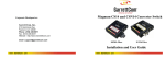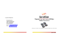
1
Corporate Headquarters GarrettCom, Inc. 47823 Westinghouse Dr. Fremont, CA 94539-7437 Phone (510) 438-9071 Fax (510) 438-9072 Website: http://www.GarrettCom.com Magnum 14E and 14EH 100Mbps Media Converters Email: [email protected] (Including SC, ST, MTRJ, LC ports, full/half duplex, multimode and singlemode with Link Pass-through) www . GarrettCom . com www . GarrettCom . com $5.00 USD Magnum 14E and 14EH Media Converters Installation and User Guide (09/09) Magnum™ 14E and 14EH Media Converters Installation and User Guide Part #: 84-00127Z Rev F Trademarks GarrettCom is a registered trademark and Magnum, Dymec, DynaStar, Personal Switch, Link-Loss-Learn, S-Ring, Convenient Switch and Converter Switch are trademarks of GarrettCom, Inc. Ethernet is a trademark of Xerox Corporation NEBS is a trademark of Telcordia Technologies UL is a registered trademark of Underwriters Laboratories www . GarrettCom . com i Magnum 14E and 14EH Media Converters Installation and User Guide (09/09) Important: The Magnum 14E and 14EH Converters contain no user serviceable parts. Attempted service by unauthorized personnel shall render all warranties null and void. If problems are experienced with Magnum 14E and 14EH Converter products, consult Section 5, Troubleshooting, of this User Guide. Copyright © 2004 GarrettCom, Inc. All rights reserved. No part of this publication may be reproduced without prior written permission from GarrettCom, Inc. Printed in the United States of America GarrettCom, Inc. reserves the right to change specifications, performance characteristics and/or model offerings without notice. www . GarrettCom . com ii Magnum 14E and 14EH Media Converters Installation and User Guide (09/09) Federal Communications Commission Radio Frequency Interference Statement This equipment generates, uses and can radiate frequency energy and if not installed and used properly, that is in strict accordance with the manufacturer's instructions, may cause interference to radio communication. It has been tested and found to comply with the limits for a Class A computing device in accordance with the specifications in Subpart J of Part 15 of FCC rules, which are designed to provide reasonable protection against such interference when operated in a commercial environment. Operation of this equipment in a residential area is likely to cause interference, in which case the user, at his own expense will be required to take whatever measures may be required to correct the interference. www . GarrettCom . com iii Magnum 14E and 14EH Media Converters Installation and User Guide (09/09) Electrical Safety requirements: 1. This product is to be installed Only in Restricted Access Areas (Dedicated Equipment Rooms, Electrical Closets, or the like). 2. 48VDC products shall be installed with a readily accessible disconnect device in the building installation supply circuit to the product. 3. This product shall be provided with a maximum 10A DC Listed fuse or circuit breaker in the supply circuit when connected to a 48V centralized source. 4. The external power supply for DC units shall be Listed, Direct Plug In power unit, marked Class 2, or listed ITE Power Supply, marked LPS, which has suitably rated output voltage (i.e. 24VDC or 48VDC) and suitable rated output current. 5. Product does not contain user replaceable fuses. Any internal fuses can ONLY be replaced by GarrettCom personnel through the RMA process. www . GarrettCom . com iv Magnum 14E and 14EH Media Converters Installation and User Guide (09/09) Contacting GarrettCom, Inc Please use the mailing address, phone and fax numbers and email address listed below: GarrettCom, Inc. 47823 Westinghouse Drive Fremont, CA 94539 Phone (510) 438-9071 Fax (510) 438-9072 Website: http://www.GarrettCom.com Email: [email protected] www . GarrettCom . com v Magnum 14E and 14EH Media Converters Installation and User Guide (09/09) TABLE OF CONTENTS Page 1.0 SPECIFICATIONS ............................................................................... 1 1.1. Technical Specifications ...................................................................... 1 1.2 Ordering Information: .......................................................................... 9 2.0 INTRODUCTION ............................................................................... 11 2.1 Inspecting the Package and Product .................................................. 11 2.2 Product Description ........................................................................... 13 2.3 Features and Benefits ......................................................................... 19 2.4 Applications ....................................................................................... 21 3.0 INSTALLATION ................................................................................. 25 3.1 Locating the Media Converter Unit .................................................. 25 3.2 MC14-TRAY for Rack Mounting of 14E Series Converters............. 26 3.3 MC14-TR+PS9 and MC14-TR+PS9X2 for Rack Mounting ............. 28 3.4 DIN-Rail mounting option ................................................................. 30 3.5 Power Requirements .......................................................................... 31 3.5.1 Powering the 14EH with 9V, 24 or –48VDC power input ....... 33 www . GarrettCom . com vi Magnum 14E and 14EH Media Converters Installation and User Guide (09/09) 14EH, -48V, 24VDC and 9VDC Installation ........................... 34 3.5.2 3.6 Calculating Segment Distances .......................................................... 36 3.6.1 Power Budget Calculations for Fiber Media .............................. 36 3.6.2 Segment Distances, Full-duplex for copper (RJ-45) and fiber .. 38 3.6.3 Segment Distances, Half-duplex mode ...................................... 43 3.6.4 Collision Domain (PDV Calculations)....................................... 43 3.7 Connecting 100Mb Ethernet Media ................................................... 51 3.7.1 Connecting Twisted Pair (RJ-45 standard) ................................ 51 3.7.2 Connecting Fiber Optic ST and SC-type, MM and SM ............. 52 3.7.3 Connecting Fiber Optic MT-RJ type “Small Form Factor” ....... 54 3.7.4 Connecting Fiber Optic LC-type “Small Form Factor” ............. 55 4.0 OPERATION ....................................................................................... 56 4.1 Dual LED Indicators (front and side-panel LEDs) ............................ 56 4.2 Up-Link or “Cross-over” Switch ( on RJ-45 port)............................ 57 4.3 Manual AN / reg Switch, auto-negotiation support .......................... 58 4.4 LINK Pass-Through feature in the 14E-series ................................... 60 5.0 TROUBLESHOOTING ...................................................................... 64 www . GarrettCom . com vii Magnum 14E and 14EH Media Converters Installation and User Guide (09/09) 5.1 Before Calling for Assistance ............................................................ 65 5.2 When Calling for Assistance ............................................................. 66 5.3 Return Material Authorization (RMA) Procedure ............................. 67 5.4 Shipping and Packaging Information................................................. 69 APPENDIX A: WARRANTY INFORMATION ......................................... 70 Revisions: Rev F 09/09: Rev E 08/08: 09/04: 06/04: Rev D 05/03: Rev C 03/03: Rev B 10/02: Rev A 09/02: Updated DIN Rail mount photo, see pg. 30, re-paginated guide Revised Input current values on page 34 Minor updates on power supplies, UL requirements. Minor updates on power supplies and Agency approvals clarified auto-negotiation support, Sec. 4.3, and 48V max of 60V DIN-Rail mounting added, Link-Pass-through feature on 14EH Link-Pass-through feature has been updated in this revision. This revision is the initial release of the User Manual for the combined 14E and 14EH Media Converters. The 14EH model is new. www . GarrettCom . com viii Magnum 14E and 14EH Media Converters Installation and User Guide (09/09) 1.0 SPECIFICATIONS 1.1. Technical Specifications Performance: Data Rate: 100 Mb/s, Half- or Full-Duplex mode, transparent Auto-negotiation supported on the RJ-45 port user selectable LINK Pass-through feature and Remote Fault Reporting (see Section 4.4 for details) Network Standards: Fast Ethernet IEEE 802.3u: 100BASE-TX, 100BASE-FX Operating Environment: Ambient Temperature: See Matrix on data sheet, max = -40ºC to 75ºC Storage Temperature: -40ºC to 85ºC Ambient Relative Humidity: 5% to 95% (non-condensing) Conformal coating (humidity protection): optional, request quote Cooling Method: Case used as heat sink on “H” models www . GarrettCom . com 1 Magnum 14E and 14EH Media Converters Installation and User Guide (09/09) Maximum Standard Fast Ethernet Segment Lengths: 100BASE-TX (twisted pair): 100 m (328 ft) 100BASE-FX Fiber optic, half-duplex: (multi-mode) 412 m (1350 ft) 100BASE-FX Fiber optic, full duplex: (multi-mode) 2.0 km (6,562 ft) 100BASE-FX Fiber optic, half-duplex: (single-mode) 412 m (1350 ft) 100BASE-FX Fiber optic, full duplex: (single-mode) 25 km (66k ft) 100BASE-FX Long Reach: Fiber optic, full duplex: (single -mode) 40 km (132k ft) For other fiber media distances and port types, request quote. Note: Magnum 14E and 14EH Media Converters DO NOT support full length shared Fast Ethernet segments. See Section 3.6 of this manual for media lengths and shared media segment distance calculations. www . GarrettCom . com 2 Magnum 14E and 14EH Media Converters Installation and User Guide (09/09) Power Supply (External): These products are intended to be supplied by a Listed, Direct Plug-In power unit, marked “Class 2”, or a Listed ITE Power Supply, marked “LPS”, which has suitably rated output voltage (i.e. 9vdc, 12vdc, 24vdc, 48vdc), and suitably rated output current (i.e. 100mA to 500mA).When connected to a 48 V centralized dc source these products shall be provided with a Listed 5 A DC fuse in the supply circuit. 120V AC at 60 Hz, for “-d” North American models 230V AC at 50 Hz, IEC built in, for “-i” intl models 100-240V AC at 50-60Hz, for “-Hd” high temp. 100-240V AC at 50-60Hz, for “-Hi” w/ adapter kit www . GarrettCom . com 3 Magnum 14E and 14EH Media Converters Installation and User Guide (09/09) DC to unit: 9V DC, 2.5mm jack, center +ve, 6ft. cord Power Supply ( DC Direct): 9V DC internal (range of 7.5 to 15V DC), built-in terminal block for +, -, ground. The 9V DC jack is also present. 24V DC internal (range of 18 to 36V DC), built-in terminal block for +, -, ground. The 9V DC jack is also present -48V DC internal (range of 36 to 60V DC), built-in terminal block for +, -, ground. The 9V DC jack is also present. Power Consumption: 3 watts typical and 3.5 watts max. for all models www . GarrettCom . com 4 Magnum 14E and 14EH Media Converters Installation and User Guide (09/09) Manual Switches Up-link (TX port): Thumb operated slide switch, converts RJ-45 TX port from a regular (= position) user segment port to a crossover (X position) uplink port for connection to a shared or switched hub. AN/reg (TX port): The AN/reg manual switch is for user-selected autonegotiation support, or for regular operation. See Section 4.3 Connectors: RJ-45 Port: shielded 8-Pin female, with “cross-over” up-link switch Fiber, multi-mode (up to 2Km) : SC-type (snap-in): Fiber optic multi-mode, 100BASE-FX ST-type (twist-lock): Fiber optic multi-mode, 100BASE-FX MT-RJ-type, Small Form Factor (plug in): Multi-mode, 100BASE-FX www . GarrettCom . com 5 Magnum 14E and 14EH Media Converters Installation and User Guide (09/09) Fiber, single-mode (15-Km and up): “SSC” SC-type (snap-in): Fiber optic single-mode, 100BASE-FX, 20Km “SST” ST-type (twist -lock): Fiber optic single-mode, 100BASE-FX, 20Km “SLC” LC-type (snap-in): Fiber optic single-mode, 100BASE-FX, 15Km “SSCL” SC-type (snap-in): “Long-Reach” single-mode, 100BASE-FX, 40Km Request quote for other fiber port types desired. Packaging: Enclosure: High strength sheet metal. Dimensions: 3.5 in H x 3.0 in W x 1.0 in D (8.9 cm x 7.6 cm x 2.5 cm) Weight: Media Converter unit: 8.6 oz or 245g Power Supply: -d, i: 5.8oz (165g) Power Supply: Hd, Hi :3.8 0z (110g) www . GarrettCom . com 6 Magnum 14E and 14EH Media Converters Installation and User Guide (09/09) LED Indicators for the Magnum 14E and 14EH (Dual, on front and on end) : PWR ON for power applied. Note: The 14E and 14EH’s have standard Link Pass-through (LPT) feature, see Section 4.4 LINK, Fiber port Steady ON when both attached cable segments are operational at their respective other ends, blinking when receiving Remote Fault from the other end. Note: See Section 4.4 for LINK LEDs LINK-Pass-through and LINK LEDs Interpretation LINK, Copper port Steady ON when the attached cable segments are operational at their respective other ends RX/ACT Activity, blinking indicates port is receiving Metal Mounting clips : included DIN-Rail mounting option: Model # DIN-RAIL-MC2 Rack-mount option: MC14-TRAY, see http://www.garrettcom.com/mc_tray.htm www . GarrettCom . com 7 Magnum 14E and 14EH Media Converters Installation and User Guide (09/09) Agency Approvals: UL Listed (UL 60950), cUL , CE, Emissions meet FCC Part 15, Class A NEBS L3 and ETSI compliant H model: IEEE P1613 Env. Std for Electric Power Substations H model: NEMA TS-2 and TEES for traffic control equipment H model: designed for UL 2043 above-the-ceiling installation IEC61850 EMC and Operating Conditions Class C for Power Substations Warranty: Three years, return to factory www . GarrettCom . com 8 Made in USA Magnum 14E and 14EH Media Converters 1.2 Ordering Information: Installation and User Guide (09/09) The model number is the base unit type, the fiber flavor, and the power supply type. The “ff” field is for your selections of your desired “fiber flavor” (see table below) “SC” = 100BASE-FX-SC: fiber optic multi-mode with SC type, 2km “ST” = 100BASE-FX-ST: fiber optic multi-mode with ST type, 2km “MTRJ” = 100BASE-FX-MTRJ: fiber optic multi-mode w/ MTRJ type, 2km “SSC” = 100BASE-FX-SSC: fiber optic single-mode with SC type, 20km “SSCL” = 100BASE-FX-SSCL: fiber optic single-mode with SC type, 40km “SST” = 100BASE-FX-ST: fiber optic single -mode with ST type, 20km “SLC” = 100BASE-FX-SLC: fiber optic single -mode with LC type, 15km www . GarrettCom . com 9 Magnum 14E and 14EH Media Converters Model Number Installation and User Guide (09/09) Description Magnum 14E-ff-d (office) Twisted pair to mm fiber “ff”, ext. 120 vac, 60Hz power supply Magnum 14E-ff-I (office) Twisted pair to mm fiber “ff”, ext. 230 vac, 50Hz power supply Magnum 14E-ff-Hd (Industrial) Twisted pair to mm fiber “ff”, ext. 100-240 vac, 50-60 Hz power supply Magnum 14E-ff-Hi (Industrial) Twisted pair to mm fiber “ff”, ext. 100-240 vac, 50-60 Hz power supply Magnum 14EH-ff-Hd (Ext. temp.AC ) Twisted pair to mm fiber “ff”, ext. 100-240 vac, 50-60 Hz power supply Magnum 14EH-ff-Hi (Ext. temp. AC) Twisted pair to mm fiber “ff”, ext. 100-240 vac, 50-60 Hz power supply Magnum 14EH-ff-9V DC (Ext. temp.DC) Twisted pair to mm fiber “ff”, int. 9V DC(7.5-15V DC) power supply Magnum 14EH-ff-24V DC (Ext. temp.DC) Twisted pair to mm fiber “ff”, int. 24V DC(18-36V DC) power supply Magnum 14EH-ff—48V DC (Ext. temp.DC)Twisted pair to mm fiber “ff”, int. -48V DC(30-60V DC) power supply MC14-TR+ PS9 = 19” Rack-mount tray , support up to 10 units of 100Mbps 14E Fiber Media Converters, Uses 2U rack space, has space for a few external PS units (which are part of the MC’s) MC14-TR+PS9X2 = Powered 19” Rack-mount tray for 100Mb, 14E (and 10Mbps, TF14 mix and match) Media Converters, up to 16 units @ 9vdcs. Uses 2U rack space. Includes common multi-unit Power Supply for universal AC input, 55 watts at 9vdc, and power cabling for the MC’s www . GarrettCom . com 10 Magnum 14E and 14EH Media Converters 2.0 INTRODUCTION Installation and User Guide (09/09) This section describes the Magnum 14E and 14EH Fast Ethernet Media Converters, including appearance, features and possible applications. 2.1 Inspecting the Package and Product Examine the shipping container for obvious damage prior to installing this product; notify the carrier of any damage which you believe occurred during shipment or delivery. Inspect the contents of this package for any signs of damage and ensure that the items listed below are included. This package should contain: 1 Magnum 14E or 14EH Media Converter unit 1 External Power Supply, (except for internal DC power supply models) 1 Set of two (2) metal mounting clips, with screws 1 User Guide (this manual) www . GarrettCom . com 11 Magnum 14E and 14EH Media Converters Installation and User Guide (09/09) Remove the Magnum 14E or 14EH Media Converter from the shipping container. Be sure to keep the shipping container should you need to store or to ship the unit at a later date. To validate the product warranty, please complete and return the enclosed Product Registration Card to GarrettCom, Inc. within two weeks of purchase. In the event there are items missing or damaged, contact your supplier. If you need to return the unit, use the original shipping container. Refer to Section 5, Troubleshooting, for specific return procedures. www . GarrettCom . com 12 Magnum 14E and 14EH Media Converters 2.2 Product Description Installation and User Guide (09/09) Rugged packaging, a selection of extended temperature models, choice of AC and DC power types, ease-of-use features, and energy-efficiency are the primary characteristics of the Magnum 100Mb 14E and 14EH Media Converters. Available with a choice of all popular multi- and single-mode fiber connector types (ST, SC, MTRJ, LC), the Magnum 14series serves the fiber media of the customer’s choice. The Hardened version Magnum 14EH is specially designed for use in uncontrolled temperature sites and fills the needs for outdoor applications as well as harsh industrial environments. The 14EH is enclosed in a sealed metal case which is used as a heat sink. The plenum-rated 14EH has an ambient temperature rating of -40°C to +75°C and has a built-in DC power supply with models for 9V, 24V, and –48V nominal ratings. The 14Es offer a convenient, cost-effective and graceful way to incorporate fiber media into a 100BASE-TX Ethernet network. Each of the many 14Es supports both full- and half-duplex mode transparently so that an attached RJ-45 switch or hub operates at its highest performance level. For support of “N-way” auto-negotiating switches, a manual AN/reg switch on the Magnum 14Es allows the user to manually enable either (a) “AN” for www . GarrettCom . com 13 Magnum 14E and 14EH Media Converters Installation and User Guide (09/09) auto-negotiation, where the 14Es transmits applicable auto-negotiation Fast Link Pulses (FLPs) from the RJ-45 port to the connected 10/100 switch port at Link-enable, or (b) “reg” regular media converter mode, no auto-negotiation. R Li X/ nk A COPPER C P wr R X\ A FIBER C Li nk GarrettCom Ethernet at its Best R Li X/ nk A COPPER C Ac Li t nk P wr R X\ A FIBER C Li nk GarrettCom A N UP LINK/ FF Ethernet at its Best Ac Li t nk A N UP LINK/ FF 100 Mb/s 100 Mb/s Magnum Media Rx /A ct Magnum 14EH Li nk 9V D C .1 A M T www.GarrettCom.com Magnum 14E with MTRJ Conn. Li nk R X R 9 V D C .1 A Rx /A ct Hardened Media Converter T www.GarrettCom.com Magnum 14EH with SC Conn. Magnum 14E and 124EH Media Converters are designed for quick and easy installation even in very tight spaces and can be easily attached to the media cables. Magnum www . GarrettCom . com 14 Magnum 14E and 14EH Media Converters Installation and User Guide (09/09) 14Es feature an up-link switch on the RJ-45 port to eliminate the need for a special cross-over cable when connecting the Copper port to a switch or hub. Because of their compact size, Magnum 14Es can be Velcro®-mounted on an office wall or the side of a desk or cabinet. Mounting options include panel-mounting using metal brackets supplied with the unit, and a DIN-rail mounting kit. Rack-mount trays ( MC14-TRAY) that neatly holds the units and associated power supplies are available. See Section 3.2/3.3 for details. The standard “1-per-unit” external power supply plugs into a nearby AC wall socket or power strip. The 14EH (Hardened) media converter is also available with extended temperature AC external power supply, and has a selection of DC internal power Supplies. See Section 3.5, Power Supply types, for various AC and DC options. The14Es MediaConverter features two full sets (front and side) of LEDs that convey essential status information in any mounting arrangement. See Section 4.1, LED Indicators, for LED function information. Magnum 14Es Media Converters are designed to operate at high ambient temperatures over an extended period, making them some of the most reliable in the industry. The high-strength, rugged sheet metal enclosure of Magnum 14EH, easily shields Magnum www . GarrettCom . com 15 Magnum 14E and 14EH Media Converters Installation and User Guide (09/09) 14Es against Radio Frequency Interference (RFI) and Electromagnetic Interference (EMI), avoiding interference with other nearby electronic devices. R Li X/ nk A COPPER C P wr R X\ A FIBER C Li nk GarrettCom Ethernet at its Best Ac Li t nk Twisted (100BASE- A N UP LINK/ FF 100 Mb/s Magnum 14EH Rx /A ct Hardened Media Converter Li nk R X 9V D C .1 A M T (100BASEMulti- mode (ST-Type) www.GarrettCom.com 14EH with Fiber ST integrates 100BASE-TX and FX networks Magnum 14E-ST models are equipped with one multi-mode fiber-ST and one RJ-45 connector for connection into 100BASE-FX segments. The Magnum 14Es units comply with the IEEE 802.3u auto-negotiation on the copper port when the user selects AUTO mode. The Link Pass-Through feature is especially desirable for use in managed networks, and is standard in all 14E and 14EH models. www . GarrettCom . com 16 Magnum 14E and 14EH Media Converters Installation and User Guide (09/09) The Magnum 14E and 14EH supports three different SC-type fiber transceivers. Model suffixes are -SC (multi-mode, 2Km), -SSC (single-mode, 25Km) or -SSCL (single-mode Long Reach, 40Km). The ST connector is available for multi-mode, and special order for single-mode. Twisted R Li X/ nk A COPPER P wr R X\ A FIBER Li nk GarrettCom Ethernet at its Best Ac Li nk (100BASE- A N UP LINK/ 100 Mb/s Magnum Media Rx /A ct Li nk R 9 V D C .1 T www.GarrettCom.com Fiber Multi(100BASE(SC- www . GarrettCom . com 17 Magnum 14E and 14EH Media Converters Installation and User Guide (09/09) The newest fiber port types (SFF, small form factor) are supported. The Model 14EMTRJ (multi-mode, 2Km), equipped with one fiber MTRJ-type port and one RJ-45 port, connects into 100BASE-FX and 100BASE-TX compliant Fast Ethernet network segments. The SFF MT-RJ connector is keyed so that it can only be connected when the two fiber strands are correctly positioned for transmit and receive. See Section 3.7.3. The LC-type is available for single-mode 15Km use. Twisted R Li X/ nk A COPPER P wr R X\ A FIBER Li nk GarrettCom Ethernet at its Best Ac Li nk (100BASE- A N UP LINK/ 100 Mb/s Magnum 14E Media Converter Rx /A ct Li nk R 9 V D C .1 T www.GarrettCom.com Multi(100BASE(MTRJ- SFF 14Es integrate 100BASE-TX and FX networks, with fiber MT-RJ mm connectors. www . GarrettCom . com 18 Magnum 14E and 14EH Media Converters 2.3 Features and Benefits Installation and User Guide (09/09) Regular (for offices) and Hardened (for industrial) models All of the models are available with a choice of power supply types, AC and DC, for use in protected as well as harsh environments. Choice of 100Mb Ethernet Fiber port connector types Models of the Magnum 14E’s are available with all of the popular fiber connectors: ST, SC mm and single-mode, MT-RJ (SFF), and LC (SFF). Full-duplex or Half-duplex transparent, auto-negotiation support Magnum 14E’s support both full-duplex and half-duplex mode transparently, and are suited for use with 100Mb Ethernet switches supporting (or not supporting) auto-negotiation. DC Power Supply choices for Industrial uses The Hardened 14EH models include built-in DC supply. The choices of DC nominal input and ranges are 9V( 7.5 to 15V), 24V (18 to 36V) and 48V (30 to www . GarrettCom . com 19 Magnum 14E and 14EH Media Converters Installation and User Guide (09/09) 60V). Screw terminals are +, -, and Ground (floating). These models may be used in “outdoor” temperature un-controlled sites, ambient of –40`C to 75`C. Rugged, Compact, Lightweight Design Featuring a compact and lightweight metal case with an external power supply, Magnum 14E and 14EH Media Converters can be conveniently installed in minimal space. The MC14-TRAY provides optional rack-mounting. DIN-Rail mounting kits are available for shop-floor industrial cabinet applications. Two sets of LEDs for viewing status from any angle. Each 14Es Media Converter is equipped with a two sets (front and side) of LEDs to provide status information when viewed at any angle or mounting arrangement, rack-mount Tray or wall-mount. Link Pass-through and Remote Fault Reporting are standard These features, desired and useful mainly in managed networks, are standard in all Magnum 14E and 14EH models. www . GarrettCom . com 20 Magnum 14E and 14EH Media Converters 2.4 Applications Installation and User Guide (09/09) The primary function of a Magnum 14Es Media Converter is to permit two different media types to coexist within the same network by allowing data to be transmitted / received between different media types. Magnum 14Es media converters provide an efficient and effective solution for a network environment where auto-negotiation is a primary concern for the attached devices. They also support 100Mb half duplex or full duplex mode, transparent. Because of its auto-negotiation feature, the Magnum 14Es supports an attached “N-way” autonegotiating RJ-45 switch or hub port, allowing it to operate at its highest performance, i.e., full-duplex 100Mb/s. Magnum 14Es are typically used where new 10/100Mb switches or switching hubs with auto-negotiating RJ-45 ports are being installed, and where full-duplex fiber segments (of up to 2Km for multi-mode or 25Km to 40Km for single mode) are needed to interconnect them with other 100Mb switches or switching hubs in distant wiring closets. Alternatively, a server with a full-duplex NIC may need to be connected via fiber to a 100Mb switches or switching hubs with RJ-45 ports. www . GarrettCom . com 21 Magnum 14E and 14EH Media Converters Installation and User Guide (09/09) 1 13 1 13 2 14 3 15 4 16 5 6 17 18 7 19 8 9 20 21 2 14 3 15 4 16 6 17 7 18 8 19 9 20 21 10 11 12 22 23 24 100 BASE-TX wiring segment UP L INK Rx/Act Link TX RX An/FF Rx/Act Pwr Link Link Link An/FF UP L INK Link Act UP LINK RX/ACT FIBER Magnum 14E UP L INK Media Converter RX\ACT RX/ACT Link Pw r Link RX\ACT TWI STED P AIR 100 BASE-TX wiring segment Link Act Magnm14E Magnum 14E RX 9VDC .3AMP 5 10 11 12 22 23 24 TX 100 BASE-FX wiring segment Two Magnum 14E’s provide connectivity for 100Mbps switches or hubs via fiber www . GarrettCom . com 22 Magnum 14E and 14EH Media Converters Installation and User Guide (09/09) In these and similar situations, the Magnum 14Es conveniently converts the twisted pair cable to fiber, allowing use of any available RJ-45 Fast Ethernet switched port with a new or existing fiber cable. See Section 3.6.2 for cable distance calculation information. Where shared Fast Ethernet segments are used, such as with Fast Ethernet switches or switching hubs with RJ-45 ports, it may be desirable to connect one or more servers or users via fiber cable. Because of its manual AN/reg switch feature, the Magnum 14Es support both “Auto-negotiation” and “reg” regular mode at the attached RJ-45 port, allowing flexibility with the unit attached. See Section 4.4 for details on auto-negotiation support. It is necessary to calculate the PDV of the overall collision domain (see Section 3.6.4) for proper operation of the Magnum 14Es in HDX applications. www . GarrettCom . com 23 Magnum 14E and 14EH Media Converters R Li X/ nk A COPPER C P wr R Li X\ nk A FIBER C GarrettCom Ethernet at its Best Installation and User Guide (09/09) 1 13 2 14 3 1 13 2 14 3 1 13 2 14 3 4 16 5 15 15 4 16 5 4 16 5 15 6 17 17 7 18 6 18 6 17 8 19 7 19 7 18 9 20 8 20 8 19 10 21 9 21 9 20 11 22 10 22 10 21 12 23 11 23 11 22 12 12 23 Twisted 100BASE-TX wiring Ac Li t nk A N UP LINK/ FF 100 Mb/s Magnum 14E Media Converter Rx /A ct Li nk R X 9 V D C .1 A T www.GarrettCom.com Fiber Multi(100BASEwiring Magnum 14E- A typical Magnum 14E application is to convert copper media to fiber, with autonegotiation support for the attached device on the copper port. www . GarrettCom . com 24 Magnum 14E and 14EH Media Converters 3.0 INSTALLATION Installation and User Guide (09/09) This section describes the installation of the Magnum 14Es Media Converters, including location, segment distance calculation and media connection. 3.1 Locating the Media Converter Unit The compact and lightweight design of the Magnum 14Es Media Converter allows it to be easily installed in most any location. A Velcro strip and a set of two metal clips and screws are included (either may be used) for mounting the unit on a vertical surface such as a wall or cabinet, or for www . GarrettCom . com 25 Magnum 14E and 14EH Media Converters Installation and User Guide (09/09) securing the unit on a table-top or shelf. The installation location is dependent upon the physical layout of the Ethernet network and associated cabling. Make sure the unit is installed in a location that is easily accessible to an AC power outlet or power strip, and where convection cooling is not inhibited. 3.2 MC14-TRAY for Rack Mounting of 14E Series Converters For 19” rack-mounting of Magnum 14Es Media Converter, a rack-mount tray is available, MC14-TRAY. The Media Converter units are mounted with their DC power jack in the back, and with the RJ-45 and the fiber ports in front. Any mix of the “14”series 10Mb Media Converters and 14Es may be placed on a tray, up to a maximum of 16 units. www . GarrettCom . com 26 Magnum 14E and 14EH Media Converters Installation and User Guide (09/09) The mounting spaces of the MC14-TRAY are specific to the 10Mb “14”-series and the 14Es, and do not permit other models or other sizes to be put in the tray. A typical installation of the model MC14-TRAY, 19” rack-mount tray will hold a few (often three to eight) 14Es Media Converters, each with their power supply plugged into power strips (not included) in the rear area of the tray. Metal mounting screws in the bottomfront hold the media converters firmly in place in the tray. www . GarrettCom . com 27 Magnum 14E and 14EH Media Converters Installation and User Guide (09/09) 3.3 MC14-TR+PS9 and MC14-TR+PS9X2 for Rack Mounting The MC14-TR+ PS9 and MC14-TR+PS9X2 are another option available for Rack Mounting the mix-match of 10Mbps and 100Mbps Media Converters together in 19” rackmount tray. These models comes with built-in common universal AC power supply rated at 55 watts at 50C ambient, 9VDC output, and supporting up to 10 MC for MC14-TR+PS9 and 16 units of Fiber media converters for MC14-TR+PS9X2. The MC14-TR+PS9X2 Model has two groups of eight units per power supply. These models are equipped with Auto-ranging AC input to the power supplies for use worldwide. (The MC mounting spaces of the MC14 -TR models are specific to the Magnum 10Mbps (TF14) and 100MB (14E) series, and do not permit other models or other sizes to be put in the tray). www . GarrettCom . com 28 Magnum 14E and 14EH Media Converters Installation and User Guide (09/09) The side-view picture shown here is an example of an installation of the model MC14TR+PS9, 19” rack-mount tray, holding a few 100Mbps 14E Media Converters, each with their power input plugged into the built-in common AC power supply in the rear area of the tray. (PS units that come with the MC’s are not used). Metal mounting screws in the bottom-front hold each of the media converters secure in the tray, separately removable for service. The dual LEDs permit viewing operating status of the Media Converters from any angle. www . GarrettCom . com 29 Magnum 14E and 14EH Media Converters 3.4 DIN-Rail mounting option Installation and User Guide (09/09) The Magnum 14E and 14EH Media Converters, designed for use in “Factory Floor” Industrial Ethernet environments, are also available for DIN-Rail mounting in an enclosure having DIN Rails. The metal DIN-Rail mounting hardware is optional and needs to be ordered as a separate item, e.g. Model # DIN-RAIL-MC2. It comes with four screws to attach the bracket to the MC unit. The Magnum 14E Models with “HR” have 24VDC power, and have the DIN-Rail-MC2 bracket included and assembled at the factory. A Magnum 14EH is shown alongside the DIN-Rail-MC2 bracket www . GarrettCom . com 30 Magnum 14E and 14EH Media Converters 3.5 Power Requirements Installation and User Guide (09/09) Magnum 14E and 14EH Media Converters require 3 watts of power typical and 3.5 watts max. and are designed to be used with UL listed Class II power supplies. The power supply unit supplied with the 14EH can vary as per application and user choice to support regular extended temperature sites. The following power supply options are available with 14E and 14EH: OFFICE Environments, Magnum 14E AC-DC to unit: 9V DC, 2.5mm jack, center +ve jack, 6ft. cord 120V AC at 60 Hz, for “-d” North American models 230V AC at 50 Hz, IEC built in, for “-i” intl models with IEC320 connector built in. www . GarrettCom . com 31 Magnum 14E and 14EH Media Converters Installation and User Guide (09/09) Industrial Temperature un-controlled Environments, Magnum 14EH Heavy Duty AC-DC adapter : 9V DC, 2.5mm jack, center +ve jack, 6ft. cord AC input, 100-240V AC at 50-60Hz, with IEC connector built-in Order the “-Hd” model for North-America with AC power cord and “-Hi” model with AC power cord for International Applications For Direct DC applications, the 14EH has built-in terminal block for +ve, -ve and gnd 9V DC internal (range of 7.5 to 15V DC) 24V DC internal (range of 18 to 36V DC) -48V DC internal (range of 36 to 60V DC) Power Consumption: 3 watts typical and 3.5 watts max. for all models www . GarrettCom . com 32 Magnum 14E and 14EH Media Converters Installation and User Guide (09/09) The various models of DC power type and extended ambient temperature power supplies are numerous and your choice needs to be called out on your order. Note: When connected to a -48 V centralized dc source these products are to be installed only in Restricted Access Areas (dedicated equipment rooms, electrical closets or the like). 3.5.1 Powering the 14EH with 9V, 24 or –48VDC power input Each Magnum 14EH equipped with an internal DC power source, and has built –in screw terminals for secure attachment of the power leads. The three model choices are for use with 9VDC, 24VDC or -48VDC. DC power input may be chosen for high-availability. The extended temperature capability of the DC-powered 14EH’s can go outdoors, rated at –40`C to +75`C. If indoors, the DC jack is also present and optionally can be used with an external AC power supply. www . GarrettCom . com 33 Magnum 14E and 14EH Media Converters Installation and User Guide (09/09) DC Power Terminals: “+”, “-”, internally floating GND: Terminal for “earth” or ground wire connection to the P62F chassis Input Voltage: 7.5 - 15V DC.( 9V DC) 18 - 36V DC (24VDC) 30 - 60V DC ( –48DC) Input current: 0.4 amp max. (9V DC) 0.2 amp max.(24V DC) 0.1 amp max. (-48V DC) Power Consumption: 3 watts typical, 3.5 watts max. for all the models. 3.5.2 14EH, -48V, 24VDC and 9VDC Installation This section describes the proper connection of the -48VDC leads (or 24VDC, 9VDC leads) to the DC power terminal block on the Magnum 14EH hardened media converter (as shown in Figure above). The DC terminal block on the Magnum 14EH is located on the left side of the unit and is equipped with three (3) screw-down lead posts. The power terminals are identified as positive (+) www . GarrettCom . com 34 Magnum 14E and 14EH Media Converters Installation and User Guide (09/09) and negative (-), and they are floating inside the unit so that either of the terminal may be grounded by the user, if desired. The chassis is “earth” or ground (GND). The connection procedure is straightforward Simply insert the DC leads to the Switch’s power terminals, positive (+) and negative (-) screws. The use of Ground (GND) is optional; it connects to the Switch chassis. Ensure that each lead is securely tightened from the top screw as shown in fig. NOTE: Always use a voltmeter to measure the voltage o f the incoming power supply and figure out the +ve potential lead or -ve potential lead. The more +ve potential lead will connect to the post labeled “+ve” and the rest to the “-ve”. The GND can be hooked up at the last. When power is applied, the green PWR LED will illuminate. www . GarrettCom . com 35 Magnum 14E and 14EH Media Converters 3.6 Calculating Segment Distances Installation and User Guide (09/09) The media distance considerations are quite different for full-duplex and for halfduplex (standard Fast Ethernet) installations. Each of these situations are covered below in a separate section. 3.6.1 Power Budget Calculations for Fiber Media Receiver Sensitivity and Transmitter Power are the parameters necessary to compute the power budget. To calculate the power budget of different fiber media installations, the following equations should be used: OPB (Optical Power Budget) = PT(min) - PR(min) where PT = Transmitter Output Power, and PR = Receiver Sensitivity Worst case OPB = OPB - 1dB(for LED aging) - 1dB(for insertion loss) Worst case distance = {Worst case OPB, in dB} / [Cable Loss, in dB/Km] where the “Cable Loss” for 62.5/125 and 50/125μm (m.m.) is 2.8 dB/km, and the “Cable Loss” for 100/140 (multi-mode) is 3.3 dB/km, and the “Cable Loss” for 9/125 (single-mode) is 0.5 dB/km www . GarrettCom . com 36 Magnum 14E and 14EH Media Converters Installation and User Guide (09/09) The following data has been collected from component manufacturer’s (Agilent’s and Siemens’) web sites and catalogs to provide guidance to network designers and installers. Fiber Port Module Speed, Std. Mode Std. km Wavefdx length (hdx) nm Cable Size μm X’mitr R’cvr Worst Worst* Output Sens. OPB, distance Km, fdx PT , dB PR ,dB dB typical OPB, dB typical* distance Km, fdx 14E/14EH- 100Mb Multimode MST, MSC FX 100Mb Single14E/14EHmode FX SSC 2 (0.4) 1300 62.5/125 -20 50/125 -23.5 -31 -31 9.0 5.5 2.5 2.0 14 12 5 4 25 (0.4) 1300 -31 14 28 17.5 35 100Mb Multimode FX 2 (0.4) 1300 62.5/125 -20 50/125 -23.5 -31 -31 9.0 5.5 2.5 2.0 14 12 5 4 100Mb Singlemode FX 15+ (0.4) 1310 9/125 -15 -28 11 22 - - 100Mb Singlemode FX 40 (0.4) 1300 9/125 -5 -34 27 54 32.5 65 14E/14EHMTRJ 14E/14EHSLC 14E-SSCL Long Reach 9/125 www . GarrettCom . com 37 -15 Magnum 14E and 14EH Media Converters Installation and User Guide (09/09) * Note: The use of either multi-mode or single-mode fiber to operate at 100Mbps speed over long distances (i.e., over approx. 400 meters) can be achieved only if the following factors are both applied: • The 100Mb fiber segment must operate in full-duplex (FDX) mode, i.e. a switch (or equal external unit such as a FDX NIC) must be used, and • The worst-case OPB of the fiber link must be greater than the fiber cable’s passive Attenuation. (Attenuation = Cable loss + LED aging loss + Insertion loss + safety factor) 3.6.2 Segment Distances, Full-duplex for copper (RJ-45) and fiber Full-duplex ports, such as copper are found in switching hubs and some NICs, can receive and transmit signals simultaneously and do not experience collisions accordingly. There may be only two nodes present on a full-duplex segment. Media distance rules are not the same as for standard (half-duplex) Fast Ethernet because collision distance limitations are www . GarrettCom . com 38 Magnum 14E and 14EH Media Converters Installation and User Guide (09/09) not a factor. Specifically, fiber segments can be up to 2Km for multi-mode and up to 20Km for single mode (or 40Km for “Long Reach” single mode). The Magnum 14Es, with full-duplex operation as a standard feature, can be used in these applications. When installing the Magnum 14Es in a full-duplex segment, it is important to consider the combined overall segment length of both of the attached media types. The overall segment length is calculated by adding together the segment lengths on both sides of the Magnum 14Es Media Converters. Segment length on each side of the 14Es Media Converter is measured as a percentage of the maximum allowable standard media distance for the given media type. The percentages, when added together, must not exceed 100%. www . GarrettCom . com 39 Magnum 14E and 14EH Media Converters Installation and User Guide (09/09) Media Distance Formula for Magnum 14Es, full-duplex: X% + Y% < 100% Where X = Where Y = The segment distance on one side of the Magnum 14Es Media Converter divided by the Standard Maximum Media Distance for that media type, x 100% The segment length on the other side of the Magnum 14Es Media Converter divided by the Standard Maximum Media Distance for that media cabling type, x 100% R Li X/ nk A COPPER C The figure to the right illustrates how P wr R X\ A FIBER C Li nk GarrettCom a Magnum 14Es Media Converter is Ethernet at its Best Ac Li t nk Twisted (100BASE- A N UP LINK/ FF 100 Mb/s used to connect a multi-mode fiber Magnum 14EH Rx /A ct Hardened Media Converter R (100BASE-FX) with a twisted pair 9V D C .1 A M T www.GarrettCom.com (100BASE-T) segment. www . GarrettCom . com 40 Li nk (100BASEMulti- mode (ST-Type) Magnum 14E and 14EH Media Converters Installation and User Guide (09/09) In the example figure shown above, the length of fiber Segment X is 1500m (4920 ft). This is 75% of the maximum allowable distance for multi-mode 100BASE-FX fiber fullConnectivity between 100BASE-TX and 100BASE-FX Ethernet Media. duplex media (2000 m) [75/2000 x 100% = 75%]. The length of twisted pair Segment Y is 10m (33 ft). This is 10% of the maximum allowable distance for 100BASE-TX full-duplex twisted-pair media (100 m) [10/100 x 100% = 10%]. The total of the two percentages (75% + 10%) is 85%, which is allowable. Note 1: Where more than one media converter is used in one segment run, the percentages for all of the cabling lengths in the run must be added together and must not exceed 100%. www . GarrettCom . com 41 Magnum 14E and 14EH Media Converters Installation and User Guide (09/09) In another instance, a 14Es Magnum Media Converter is used to connect a single mode fiber (100BASE-FX) with a twisted pair (100BASE-T) segment. In this example, the length of fiber Segment X is 8500m (27,880 ft). This is 57% of the maximum allowable distance for single mode 100BASE-FX fiber full-duplex media (15,000 m) [57/15,000 x 100% = 57%]. The length of twisted pair Segment Y is 12m (40 ft). This is 12% of the maximum allowable distance for 100BASE-TX full-duplex twisted-pair media (100 m) [12/100 x 100% = 12%]. The total of the two percentages (57% + 12%) is 69%, which is allowable. www . GarrettCom . com 42 Magnum 14E and 14EH Media Converters 3.6.3 Installation and User Guide (09/09) Segment Distances, Half-duplex mode Fast Ethernet shared bandwidth devices operate with multiple nodes in a traffic domain. When a node attempts to send a packet, it may hit another packet passing by, i.e., a collision may occur. This is normal and does not cause a problem because the Ethernet protocol provides for this situation and requires that the sender wait and try again. When installing the Magnum 14E in a half-duplex segment, it is important to consider the collision domain of the segment, including the 14E itself, repeaters and hubs present, and the lengths of both of the attached media types. 3.6.4 Collision Domain (PDV Calculations) A collision domain is defined in the IEEE 802.3u standard as a cluster of network devices that, regardless of topology, must be less than 512 BT (Bit Times) of signal delay (PDV or Path Delay Value) in diameter between any two nodes. Nodes in a collision domain www . GarrettCom . com 43 Magnum 14E and 14EH Media Converters Installation and User Guide (09/09) are connected by means of a repeater or repeaters such that no bridging or switching devices are present between any two nodes in the cluster. Magnum 14Es has a PDV of about twenty Bit Times (20 BT), and this value must be included in the overall collision domain diameter PDV calculations as applicable for the placement of the 14Es in the topology of the collision domain. Collision Domain Diameter The Collision Domain Diameter is the length of the longest path between any two devices in a single collision domain. Regardless of the actual network topology, the Collision Domain Diameter must be less than 512 BT (Bit Times). Bit Times are related to media type as shown in Table 3.6.4a. www . GarrettCom . com 44 Magnum 14E and 14EH Media Converters Installation and User Guide (09/09) Table 3.6.4a: Worst case round-trip delay for Fast Ethernet media* Media Type Round-trip delay in Bit Time per Meter (BT/m) 1.000 Fiber Optic 1.112 Shielded TP cable 1.112 Category 5 Cable 1.140 Category 4 Cable *Worst case delays taken from IEEE Std 802.3u-1995, actual delays may be less for a particular cable. Contact your cable supplier for exact cable specifications. Each shared Fast Ethernet network device also has an associated BT delay. Table 3.6.4b shows typical Fast Ethernet device components and the associated BT delay. Note that there is only one DTE pair associated with any device-to-device path. www . GarrettCom . com 45 Magnum 14E and 14EH Media Converters Installation and User Guide (09/09) Table 3.6.4b: Worst case round-trip delay for Fast Ethernet device components* Component Round-trip delay in Bit Times (BT) 100 2 TX DTEs 100 2 FX DTEs 100 1 FX and 1 TX DTE 127 1 T4 and 1 TX or FX DTE 140 Class I Repeater 92 Class II Repeater with any combination of TX and FX ports *Worst case delays taken from IEEE Std 802.3u-1995. To determine whether a prospective network topology adheres to the collision domain diameter specification, the following formula should be applied to the worst case path through the network. The worst case path is the path between the two Fast Ethernet devices (DTEs) which have the longest round trip delay time. www . GarrettCom . com 46 Magnum 14E and 14EH Media Converters Installation and User Guide (09/09) PDV = (sum of cabling delays) + (sum of repeater and media converter delays) + (DTE pair delays) + (safety margin) PDV is the Path Delay Value of the worst case path. For the network to adhere to IEEE 802.3u standard, this value must be less than 512 BT. The safety margin is specified in BT and may be a value between 0 and 5. This margin can be used to accommodate unexpected delays, such as an extra long patch cable. A safety margin of at least 2 to 4 BT is recommended. “Rules-of-thumb” Collision Domain Calculations Rules-of-thumb, while inexact, may be helpful in planning network topology. As a rule-of-thumb, a Class II Repeater has a PDV of about 90 to 95 BTs, and twisted-pair or fiber www . GarrettCom . com 47 Magnum 14E and 14EH Media Converters Installation and User Guide (09/09) media has a PDV of about 1 BT per meter of length. The Magnum 14E has a PDV of 20 BT. Therefore, in shared Fast Ethernet applications, the 14E uses about 80 meters of equivalent cable distance to convert from TX media to fiber FX media, i.e., it consumes almost as much of the available PDV as a Class II repeater. Since a 512BT collision domain will almost always include at least one repeater and two media segments, the remaining amount of Bit Times left after allowing for a 14Es and a length of fiber media indicates that the available fiber length will be much less than the 412 meters that is the known maximum for fiber. Therefore, in shared environments, Magnum 14Es Media Converters will be of benefit when they allow the use of fiber media, but not to gain distance by facilitating use of fiber media instead of twisted pair. As a sample calculation, consider the question of what fiber cable distance (connected by a pair of Magnum 14Es on each end) can be obtained that will interconnect two www . GarrettCom . com 48 Magnum 14E and 14EH Media Converters Installation and User Guide (09/09) 100Mb hubs where the twisted pair cables to the user nodes are 10 meters in length. The solution is : 512 = total available Bit Times in a collision domain diameter, minus 100 BT for two DTEs on each end leaves 412 BTs, minus 180 BT for two Class II repeaters leaves 232 BTs, minus 20 BT for two 10-meter TP cables for hubs to users leaves 212 BTs, minus 10 BT for two short TP cables from the hubs to 14E’s leaves 202 BTs, minus 40 BT for two Magnum 14Es leaves 162 BTs for fiber cable, which indicates a fiber cable length of about 160 meters. It is obvious that using twisted pair wiring to connect the hubs would enable the interconnect length to be the 100 meters maximum for twisted pair media, and this would still leave about a hundred BTs as a safety margin. In other words, use of 14Es and fiber in this case did not gain allowable maximum cable distance vs. TP cable without the 14Es. Consider a more typical use of Magnum 14Es in a shared Fast Ethernet segment. A www . GarrettCom . com 49 Magnum 14E and 14EH Media Converters Installation and User Guide (09/09) stack of Fast Ethernet hubs comprises the only repeater in the collision domain, and the users and servers in the local workgroup are each connected via Category 5 twisted pair cable, a maximum of 30 meters (100 ft.) in length. It is desired to connect one remote user with a fiber NIC via fiber cable, using a Magnum14Es in the circuit. How long can the fiber cable be? The solution is : 512 = total available Bit Times in a collision domain diameter, minus 100 BT for two DTEs on each end leaves 412 BTs, minus 90 BT for one Class II stackable repeater leaves 322 BTs, minus 30 BT for one 30-meter TP cable from hub to user node leaves 292 BTs, minus 5 BT for a short TP cable from the hub to 14E leaves 287 BTs, minus 20 BT for one Magnum 14Es leaves 267 BTs for fiber cable, which indicates a fiber cable length of about 260 meters. www . GarrettCom . com 50 Magnum 14E and 14EH Media Converters 3.7 Connecting 100Mb Ethernet Media Installation and User Guide (09/09) Connecting Ethernet media to the Magnum 14Es Media Converter is very simple and straightforward. Using a properly terminated media segment, simply attach the cable end to the appropriate connector. See Sections 4.1 for a description of the LEDs. See Section 4.3 “Autonegotiation” and Section 4,4 “Link Pass-through” to identify the meaning of LEDs in various cases, as media connections can vary according to the device on the other end of the media and its behavior. 3.7.1 Connecting Twisted Pair (RJ-45 standard) The following procedure describes how to connect a 100BASE-TX twisted pair segment to the RJ-45 port on the Magnum 14E Media Converters. Be sure to observe autonegotiation support conventions for RJ-45 ports, see Section 4.3 The procedure is the same for both unshielded and shielded twisted pair segments. www . GarrettCom . com 51 Magnum 14E and 14EH Media Converters 1. 2. 3. 4. 3.7.2 Installation and User Guide (09/09) Using standard 100BASE-TX media, insert either end of the cable with an RJ-45 plug into the RJ-45 connector of the Magnum 14E Media Converter. Connect the other end of the cable to the corresponding device. Use the LINK LED ensure proper connectivity by noting that the LED will be illuminated when the units are powered and proper connections established. If the LINK LED is not illuminated, change the setting of the up-link switch (See Section 4.4 for up-link switch information.) If this does not help, ensure that the cable is connected properly at both ends and is not defective. For all 14Es,the Link-Pass-through feature is standard, the two LINK LEDs operate together, and either both LEDs are lit or neither is lit. Both of the attached cables must be operable for LINK to be indicated. Absence of LINK does not point to the problem cable segment, and the fault may be in either. Connecting Fiber Optic ST and SC-type, MM and SM The following procedure applies to 100BASE-FX applications using the Magnum 14E Media Converter with ST-type (twist-lock) and SC-type (snap-in) fiber connectors. 1. Before connecting the fiber optic cable, remove the protective dust caps from the tips of the connectors on the Magnum 14E. Save these dust caps for future use. www . GarrettCom . com 52 Magnum 14E and 14EH Media Converters 2. 3. 4. 5. 6. Installation and User Guide (09/09) Wipe clean the ends of the dual connectors with a soft cloth or lint-free lens tissue dampened in alcohol. Make certain the connectors are clean before connecting. Note: One strand of the duplex fiber optic cable is coded using color bands at regular intervals; you must use the color-coded strand on the associated ports at each end of the fiber optic segment. Connect the Transmit (TX) port (light colored post) on the Magnum 14Es to the Receive (RX) port of the remote device. Begin with the color-coded strand of the cable for this first “Transmit-to-Receive” connection. Connect the Receive (RX) port (dark colored post) on the 14E to the Transmit (TX) port of the remote device. Use the non-color coded fiber strand for this. The LINK LED corresponding to the fiber port, on the front of the product, will illuminate when a proper connection has been established at both ends (and when power is ON in the units at each end). If LINK is not lit after cable connection, the normal cause is improper cable polarity. Swap the fiber cables on the product connector to remedy this situation. Because of standard Link Pass Through feature the LINK indication will not be present unless LINK is made for the cables on both sides. www . GarrettCom . com 53 Magnum 14E and 14EH Media Converters 3.7.3 Installation and User Guide (09/09) Connecting Fiber Optic MT-RJ type “Small Form Factor” The following procedure applies to 100BASE-FX applications using the Magnum 14E Media Converter with MT-RJ (snap-in, two-fibers-in-one-piece) fiber connectors. 1. Before connecting the fiber optic cable, remove the protective dust cap from the tip of the connector on the Magnum 14Es. 2. Wipe clean the ends of the connector with a soft cloth or lint-free lens tissue dampened in alcohol. Make certain the connector is clean before connecting. Note: The MT-RJ connector is keyed so that it will only plug in when both TX and RX fiber elements are correctly positioned. 3. Insert the male MT-RJ part into the female MT-RJ port. This connection is keyed so that it only goes in one way, aligning the fiber pair for transmit and receive. 4. The LINK LED corresponding to the fiber port, on the front of the product, will illuminate when a proper connection has been established at both ends (and when power is ON in the units at each end). If LINK is not lit after cable connection, the normal cause is improper cable seating. Re-insert the fiber cables on the product connector to possibly remedy this situation. 5. Because of standard Link Pass-through feature, the LINK indication will not be present and act blinking unless LINK is made for the cables on both sides. www . GarrettCom . com 54 Magnum 14E and 14EH Media Converters 3.7.4 Installation and User Guide (09/09) Connecting Fiber Optic LC-type “Small Form Factor” The following procedure applies to 100BASE-FX applications using the Magnum 14Es Media Converter with LC (snap-in, two-fibers-in-one-piece) fiber connectors. 1. Before connecting the fiber optic cable, remove the protective dust cap from the tip of the connector on the Magnum 14Es. 2. Wipe clean the ends of the connector with a soft cloth or lint-free lens tissue dampened in alcohol. Make certain the connector is clean before connecting. Note: The LC connector is keyed so that it will only plug in when both TX and RX fiber elements are correctly positioned. 3. Insert the male LC part into the female MT-RJ port. This connection is keyed so that it only goes in one way, aligning the fiber pair for transmit and receive. 3. The LINK LED corresponding to the fiber port, on the front of the product, will illuminate when a proper connection has been established at both ends (and when power is ON in the units at each end). If LINK is not lit after cable connection, the normal cause is improper cable seating. Re-insert the fiber cables on the product connector to possibly remedy this situation. 4. Because of standard Link Pass-through feature, the LINK indication will not be present and act blinking unless LINK is made for the cables on both sides. www . GarrettCom . com 55 Magnum 14E and 14EH Media Converters 4.0 OPERATION Installation and User Guide (09/09) This section describes the operation of the Magnum 14Es Media Converters including LEDs function, up-link switch and auto-negotiation AN/reg functionality. For power supplies and details of the various AC (regular and extended temperature) and DC power input types (9VDC, 24VDC, -48VDC), please see “Specifications.” 4.1 Dual LED Indicators (front and side-panel LEDs) LED PWR Description Illuminates green (ON) to indicate the power applied LINK, Fiber port Steady ON when both attached cable segments are operational at their respective other ends, blinking when receiving remote fault from other end. Note: Magnum 14Es has Link Pass-through feature, see Section 4.4 for details. LINK, Copper port Steady ON when the attached cable segments are operational at their respective other ends RX/ACT Activity, blinking when receiving packets www . GarrettCom . com 56 Magnum 14E and 14EH Media Converters 4.2 Installation and User Guide (09/09) Up-Link or “Cross-over” Switch ( on RJ-45 port) Magnum 14Es Media Converters are equipped with an up-link slide switch to accommodate switch- or repeater-to-converter connections without a special cross-over cable. When set to the straight position (=), the Magnum 14Es Media Converter is wired for normal twisted pair connection to a user node device like workstation (NIC card). When set to the cross-over position (X), the Media Converter is wired with cross-over functionality for direct up-link to a network hub or switch or any other Ethernet device See Figure 4.3 on the next page for the location of the Up-Link slide switch on the Magnum 14E’s Media Converter unit. www . GarrettCom . com 57 Magnum 14E and 14EH Media Converters Installation and User Guide (09/09) 4.3 Manual AN / reg Switch, auto-negotiation support Magnum 14E and 14EH Media Converters are equipped with a tiny manual switch (AN/reg), which controls the RJ-45 port only, located just beneath the up-link. See diagram. The AN / reg switch provides the flexibility to the user to manually select either (a) Auto-Negotiation support to send Fast Link Pulses (FLP’s) to the attached device, or (b) reg mode for regular operation. In all ( ( ) up-link ) user device AN/reg Up-link Switch End vie w cases, the 14E functions at both FDX and HDX transparently, but always at 100Mbps speed. The factory default setting is AN (Auto-Negotiation). www . GarrettCom . com 58 Magnum 14E and 14EH Media Converters Installation and User Guide (09/09) The difference in the two AN/reg switch settings is for the attached port, i.e., the port in the switch or hub or NIC at the other end of the twisted pair cable. If the attached port is of the popular auto-negotiate-only variety, it needs to get FLPs from the 14E Media Converter in order to decide what to do. When connected to an auto-negotiating port, not receiving FLPs would indicate (incorrectly) that the Magnum 14E is only capable of halfduplex operation. Setting the switch in the AN position causes FLPs to be sent, advertising full-duplex capability. BUT NOTE . . . it is up to the user who chooses the AN position to determine that the device on the other end of the fiber cable is, in fact, capable of full-duplex operation. If it is not, choose the reg switch position and do not advertise full-duplex. Also note that auto-negotiation (and auto-crossover if present) only occurs at Linkenable. Changing the AN/reg switch position while LINK is ON will have no effect until Link goes down and comes back.. The reg position is also suitable for use when non-auto-negotiating devices are attached. In this case, the attached RJ-45 port (such as a traditional managed switch) is set to half- or full-duplex by the operator, and does not depend upon auto-negotiating FLPs. The 14E itself is transparent half- or full-duplex, and will always operate correctly in this situation. www . GarrettCom . com 59 Magnum 14E and 14EH Media Converters 4.4 LINK Pass-Through feature in the 14E-series Installation and User Guide (09/09) Twisted Pair 1 The LINK Pass-through feature is standard in all Magnum 14E’s and 14EH’s. Li R nk X/ A CT TWISTED PAIR P wr Li nk FIBER R X\ A CT Magnum 14E Media Converter 2 3 4 5 6 7 8 9 10 11 12 13 14 15 16 17 18 Ac Lin t k An/F F UP LINK Rx /A ct Lin k LINK LED’s, The 14E-series of RJ- 45 & Fiber media converters have two Fiber related features, namely LINK Pass-through and Remote Fault Reporting. LINK Pass-through propagates link fault conditions across a chain of one or more media converters. Remote Fault Reporting provides a mechanism where a remote link down condition is reported back to the transmitting side. Each of these is discussed further below. RX 9V D C .3 A M P TX 1 www . GarrettCom . com 60 2 3 4 5 6 7 8 9 10 11 12 13 14 15 16 17 18 19 20 21 22 23 24 19 20 21 22 23 24 Magnum 14E and 14EH Media Converters Installation and User Guide (09/09) LINK Pass-through In the regular (non-hardened) Magnum 14E units, LINK Pass-through is restricted in the direction of copper-to-fiber. It works one-way only, i.e. RJ-45 Link status pass-through to fiber, in order not to interfere with the auto-negotiation feature, if it is turned on. In the 14E series devices, this action is taken only for link-down condition at the copper port. The fiber port will stop sending out its link signal when there is a link-down condition at the copper port. The copper port will always send out its link signal, no matter what is the fiber port status. In the hardened 14EH series, LINK Pass-through is available in both directions. LINK Pass-through in simple terms means, when one port detects a link-down condition, it will stop sending out its link signal on the other port. This effectively propagates the link-down condition to the next device. www . GarrettCom . com 61 Magnum 14E and 14EH Media Converters In the 14EH-series, this action is taken for link-down condition at both the copper and fiber ports. The fiber port will stop sending out link signal when there is a link-down condition at the copper port and the copper port will stop sending out link signal when there is a link-down condition at the fiber port. Installation and User Guide (09/09) Twisted Pair 1 RX /A CT Li nk TWISTED PAIR P wr Li nk RX \A CT 4 5 6 7 8 9 10 11 12 13 14 15 16 17 18 19 20 21 22 Two LINK LED’s, both ON or both OFF Lin k TX Fiber 1 2 3 4 5 6 7 8 9 1 0 11 12 13 14 15 16 17 18 19 20 21 22 23 24 Remote Fault Reporting. All 14E series support Remote Fault Reporting as specified in the IEEE 802.3 standard. When the fiber port is in a link-down condition, it will send out a special data pattern to the link partner at the other end of the fiber cable to report that it is not getting a link signal from the partner. The partner fiber port which receives the Remote Fault Report will then display a rapidly blinking pattern at its link LED, indicating the receipt of Remote Fault Report signal. 62 24 An/FF Rx /A ct Magnum 14EH www . GarrettCom . com 23 UP LINK RX 9V DC .3 A M P 3 Ac Lin t k FIBER Magnum 14EH Media Converter 2 Magnum 14E and 14EH Media Converters Installation and User Guide (09/09) Interpretation of LINK LED signals on 14E and 14EH Media Converters The LINK LED provides useful troubleshooting information to the user. A steady-ON LINK LED indicates that port is receiving link signal from its link partner at the remote end. A steady OFF LINK LED indicates that port is not receiving link signal from its link partner at the remote end of the attached cable, which can happen either due to a cable fault in the cable segment to the link partner, or because the link partner’s power is off, or because the link partner has propagated a link-down condition from it’s other port. The actual reason can be identified if necessary by checking the status of the unit at the remote end. This way, the actual location of the no-link cause can be ascertained. www . GarrettCom . com 63 Magnum 14E and 14EH Media Converters 5.0 TROUBLESHOOTING Installation and User Guide (09/09) All Magnum Ethernet products are designed to provide reliability and consistently high performance in all network environments. The installation of Magnum 14Es Media Converters is a straightforward procedure (see INSTALLATION, Section 3.0); the operation is also straightforward and is discussed in Section 4. Should problems develop during installation or operation, this section is intended to help locate, identify and correct these types of problems. Please follow the suggestions listed below prior to contacting your supplier. However, if you are unsure of the procedures described in this section or if the Magnum 14Es Media Converters is not performing as expected, do not attempt to repair the unit; instead contact your supplier for assistance or contact GarrettCom Customer Support. www . GarrettCom . com 64 Magnum 14E and 14EH Media Converters 5.1 Before Calling for Assistance 1. 2. 3. 4. 5. Installation and User Guide (09/09) If difficulty is encountered when installing or operating the unit, refer back to the installation Section of the applicable chapter of this manual. Also check to make sure that the various components of the network are interoperable. Check the cables and connectors to ensure that they have been properly connected and the cables/wires have not been crimped or in some way impaired during installation. (About 90% of network downtime can be attributed to wiring and connector problems.) Make sure that an AC power cord is properly attached to each Magnum 14Es Media Converter unit. Be certain that each AC power cord is plugged into a functioning electrical outlet. Use the PWR LEDs to verify each unit is receiving power. If the problem is isolated to a network device other than the Magnum 14Es Media Converters product, it is recommended that the problem device is replaced with a known good device. Verify whether or not the problem is corrected. If not, go to Step 5 below. If the problem is corrected, the Magnum 14Es Media Converters and its associated cables are functioning properly. If the problem continues after completing Step 4 above, contact your supplier of the Magnum 14Es Media Converters unit or if unknown, contact GarrettCom, Inc.by fax, phone or email ([email protected]) for assistance. www . GarrettCom . com 65 Magnum 14E and 14EH Media Converters 5.2 When Calling for Assistance 1. 2. 3. 4. Installation and User Guide (09/09) Please be prepared to provide the following information. A complete description of the problem, including the following points: a. The nature and duration of the problem; b. Situations when the problem occurs; c. The components involved in the problem; d. Any particular application that, when used, appears to create the problem; An accurate list of GarrettCom product model(s)involved, with serial number(s). Include the date(s) that you purchased the products from your supplier. It is useful to include other network equipment models and related hardware, including personal computers, workstations, terminals and printers; plus, the various network media types being used. A record of changes that have been made to your network configuration prior to the occurrence of the problem. Any changes to system administration procedures should all be noted in this record. www . GarrettCom . com 66 Magnum 14E and 14EH Media Converters Installation and User Guide (09/09) 5.3 Return Material Authorization (RMA) Procedure All returns for repair must be accompanied by a Return Material Authorization (RMA) number. To obtain an RMA number, please use this URL https://rma.garrettcom.com/rma/rma_request_noaccount.php to fill out the form. Please have the following information readily available: Name and phone number of your contact person. Name of your company / institution Your shipping address Product name Serial Number (or Invoice Number) Packing List Number (or Sales Order Number) Date of installation Failure symptoms, including a full description of the problem. www . GarrettCom . com 67 Magnum 14E and 14EH Media Converters Installation and User Guide (09/09) GarrettCom will carefully test and evaluate all returned products, will repair products that are under warranty at no charge, and will return the warranty-repaired units to the sender with shipping charges prepaid (see Warranty Information, Appendix A, for complete details). However, if the problem or condition causing the return cannot be duplicated by GarrettCom, the unit will be returned as: No Problem Found. GarrettCom reserves the right to charge for the testing of non-defective units under warranty. Testing and repair of product that is not under warranty will result in a customer (user) charge. www . GarrettCom . com 68 Magnum 14E and 14EH Media Converters Installation and User Guide (09/09) 5.4 Shipping and Packaging Information Should you need to ship the unit back to GarrettCom, please follow these instructions: 1. Package the unit carefully. It is recommended that you use the original container if available. Units should be wrapped in a "bubble-wrap" plastic sheet or bag for shipping protection. (You may retain all connectors and this Installation Guide.) CAUTION: Do not pack the unit in Styrofoam "popcorn" type packing material. This material may cause electro-static shock damage to the unit. 2. Clearly mark the Return Material Authorization (RMA) number on the outside of the shipping container. 3. GarrettCom is not responsible for your return shipping charges. 4. Ship the package to: GarrettCom, Inc. 47823 Westinghouse Dr. Fremont, CA 94539-7437 Attn.: Customer Service www . GarrettCom . com 69 Magnum 14E and 14EH Media Converters Installation and User Guide (09/09) APPENDIX A: WARRANTY INFORMATION GarrettCom, Inc. warrants its products to be free from defects in materials and workmanship for a period of three (3) years from the date of shipment by GarrettCom. During this warranty period, GarrettCom will repair or, at its option, replace components in the products that prove to be defective at no charge other than shipping and handling, provided that the product is returned pre-paid to GarrettCom. This warranty will not be effective and void if, in the opinion of GarrettCom, the product has been damaged by misuse, misapplication, or as a result of service or modification other than by GarrettCom. GarrettCom reserves the right to make a charge for handling and inspecting any product returned for warranty repair which turns out not to be faulty. Please complete the warranty card as this acts as a product registration, and mail it to GarrettCom within two weeks of your purchase. www . GarrettCom . com 70