1
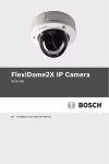
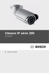
IP Camera 200 Series
NBC-225-P
en
Installation and Operation Manual
IP Camera 200 Series
Table of Contents | en
3
Table of Contents
1
Safety
7
1.1
Safety precautions
7
1.2
Important safety instructions
8
1.3
FCC & ICES compliance
1.4
UL certification
11
9
1.5
Bosch notices
11
1.6
Copyrights
12
2
Introduction
13
2.1
Features
13
2.2
Unpacking
14
3
Installation
15
3.1
Power connection
15
3.1.1
DC power connection
15
3.2
Network (and power) connector
16
3.3
I/O connector
17
3.4
Audio connectors
18
3.5
Resetting the camera
18
3.6
SD card
19
3.7
Mounting the camera
19
4
Browser connection
21
4.1
System requirements
21
4.2
Establishing the connection
21
4.2.1
Password protection in camera
22
4.3
Protected network
22
4.4
Connection established
23
4.4.1
LIVEPAGE
23
4.4.2
RECORDINGS
23
4.4.3
SETTINGS
23
Bosch Security Systems
Installation and Operation Manual
AR18-09-B003 | v1.1 | 2010.05
4
en | Table of Contents
IP Camera 200 Series
5
Basic Mode
25
5.1
Basic Mode menu tree
25
5.2
Device Access
26
5.2.1
Camera name
26
5.2.2
Password
26
5.3
Date/Time
27
5.4
Network
28
5.5
Encoder Profile
29
5.6
Audio
29
5.7
Recording
29
5.7.1
Storage medium
29
5.8
System Overview
29
6
Advanced Mode
30
6.1
Advanced Mode menu tree
30
6.2
General
31
6.2.1
Identification
31
6.2.2
Password
31
6.2.3
Date/Time
32
6.2.4
Display Stamping
34
6.3
Web Interface
36
6.3.1
Appearance
36
6.3.2
LIVEPAGE Functions
37
6.3.3
Logging
38
6.4
Camera
39
6.4.1
Encoder Profile
39
6.4.2
Encoder Streams
42
6.4.3
Video
43
6.4.4
Audio
44
6.4.5
Installer Options
44
6.5
Recording
45
6.5.1
Storage Management
46
6.5.2
Recording Profiles
49
6.5.3
Retention Time
50
6.5.4
Recording Scheduler
51
6.5.5
Recording Status
52
AR18-09-B003 | v1.1 | 2010.05
Installation and Operation Manual
Bosch Security Systems
IP Camera 200 Series
Table of Contents | en
5
6.6
Alarm
53
6.6.1
Alarm Connections
53
6.6.2
Video Content Analyses (VCA)
56
6.6.3
VCA configuration- Profiles
57
6.6.4
VCA configuration - Scheduled
63
6.6.5
VCA configuration - Event triggered
65
6.6.6
Audio Alarm
66
6.6.7
Alarm E-Mail
67
6.7
Interfaces
69
6.7.1
Alarm input
69
6.7.2
Relay
69
6.8
Network
71
6.8.1
Network
71
6.8.2
Advanced
75
6.8.3
Multicasting
76
6.8.4
JPEG Posting
77
6.9
Service
79
6.9.1
Maintenance
79
6.9.2
System Overview
81
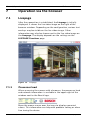
7
Operation via the browser
82
7.1
Livepage
82
7.1.1
Processor load
82
7.1.2
Image selection
83
7.1.3
Digital I/O
83
7.1.4
System Log / Event Log
83
7.1.5
Saving snapshots
83
7.1.6
Recording video sequences
83
7.1.7
Running recording program
84
7.1.8
Audio communication
84
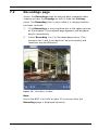
7.2
Recordings page
85
7.2.1
Controlling playback
86
8
Troubleshooting
88
8.1
Resolving problems
88
8.2
Customer service
88
Bosch Security Systems
Installation and Operation Manual
AR18-09-B003 | v1.1 | 2010.05
6
en | Table of Contents
IP Camera 200 Series
9
Maintenance
89
9.1
Repairs
89
9.1.1
Transfer and disposal
89
10
Technical Data
90
10.1
Specifications
90
10.1.1
Dimensions
92
10.1.2
Accessories
92
AR18-09-B003 | v1.1 | 2010.05
Installation and Operation Manual
Bosch Security Systems
IP Camera 200 Series
Safety | en
1
Safety
1.1
Safety precautions
7
DANGER!
High risk: This symbol indicates an imminently hazardous
situation such as "Dangerous Voltage" inside the product.
If not avoided, this will result in an electrical shock, serious
bodily injury, or death.
WARNING!
Medium risk: Indicates a potentially hazardous situation.
If not avoided, this could result in minor or moderate bodily
injury.
CAUTION!
Low risk: Indicates a potentially hazardous situation.
If not avoided, this could result in property damage or risk of
damage to the device.
Bosch Security Systems
Installation and Operation Manual
AR18-09-B003 | v1.1 | 2010.05
8
en | Safety
1.2
IP Camera 200 Series
Important safety instructions
Read, follow, and retain for future reference all of the following
safety instructions. Heed all warnings on the unit and in the
operating instructions before operating the unit.
1.
Cleaning - Generally, using a dry cloth for cleaning is
sufficient but a moist, fluff-free cloth or leather shammy
may also be used. Do not use liquid cleaners or aerosol
cleaners.
2.
Heat Sources - Do not install the unit near any heat
sources such as radiators, heaters, stoves, or other
equipment (including amplifiers) that produce heat.
3.
Water - Never spill liquid of any kind on the unit.
4.
Lightning - Take precautions to protect the unit from
power and lightning surges.
5.
Controls adjustment - Adjust only those controls specified
in the operating instructions. Improper adjustment of
other controls may cause damage to the unit.
6.
Power sources - Operate the unit only from the type of
power source indicated on the label.
7.
Servicing - Unless qualified, do not attempt to service this
unit yourself. Refer all servicing to qualified service
personnel.
8.
Replacement parts - Use only replacement parts specified
by the manufacturer.
9.
Installation - Install in accordance with the manufacturer's
instructions and in accordance with applicable local codes.
10. Attachments, changes or modifications - Only use
attachments/accessories specified by the manufacturer.
Any change or modification of the equipment, not
expressly approved by Bosch, could void the warranty or,
in the case of an authorization agreement, authority to
operate the equipment.
AR18-09-B003 | v1.1 | 2010.05
Installation and Operation Manual
Bosch Security Systems
IP Camera 200 Series
1.3
Safety | en
9
FCC & ICES compliance
FCC & ICES Information
(U.S.A. and Canadian Models Only)
This equipment has been tested and found to comply with the
limits for a Class B digital device, pursuant to part 15 of the
FCC Rules. These limits are designed to provide reasonable
protection against harmful interference in a residential
installation. This equipment generates, uses, and can radiate
radio frequency energy and, if not installed and used in
accordance with the instructions, may cause harmful
interference to radio communications. However, there is no
guarantee that interference will not occur in a particular
installation. If this equipment does cause harmful interference
to radio or television reception, which can be determined by
turning the equipment off and on, the user is encouraged to try
to correct the interference by one or more of the following
measures:
–
reorient or relocate the receiving antenna;
–
increase the separation between the equipment and
–
connect the equipment into an outlet on a circuit different
receiver;
from that to which the receiver is connected;
–
consult the dealer or an experienced radio/TV technician
for help.
Intentional or unintentional modifications, not expressly
approved by the party responsible for compliance, shall not be
made. Any such modifications could void the user's authority to
operate the equipment. If necessary, the user should consult
the dealer or an experienced radio/television technician for
corrective action.
The user may find the following booklet, prepared by the
Federal Communications Commission, helpful: How to Identify
and Resolve Radio-TV Interference Problems. This booklet is
available from the U.S. Government Printing Office,
Washington, DC 20402, Stock No. 004-000-00345-4.
Bosch Security Systems
Installation and Operation Manual
AR18-09-B003 | v1.1 | 2010.05
10
en | Safety
IP Camera 200 Series
Informations FCC et ICES
(modèles utilisés aux États-Unis et au Canada uniquement)
Suite à différents tests, cet appareil s'est révélé conforme aux
exigences imposées aux appareils numériques de classe B, en
vertu de la section 15 du règlement de la Commission fédérale
des communications des États-Unis (FCC), et en vertu de la
norme ICES-003 d'Industrie Canada. Ces exigences visent à
fournir une protection raisonnable contre les interférences
nuisibles lorsque l'appareil est utilisé dans le cadre d'une
installation résidentielle. Cet appareil génère, utilise et émet
de l'énergie de radiofréquences et peut, en cas d'installation ou
d'utilisation non conforme aux instructions, engendrer des
interférences nuisibles au niveau des radiocommunications.
Toutefois, rien ne garantit l'absence d'interférences dans une
installation particulière. Il est possible de déterminer la
production d'interférences en mettant l'appareil
successivement hors et sous tension, tout en contrôlant la
réception radio ou télévision. L'utilisateur peut parvenir à
éliminer les interférences éventuelles en prenant une ou
plusieurs des mesures suivantes:
–
Modifier l'orientation ou l'emplacement de l'antenne
réceptrice;
–
Éloigner l'appareil du récepteur;
–
Brancher l'appareil sur une prise située sur un circuit
différent de celui du récepteur;
–
Consulter le revendeur ou un technicien qualifié en radio/
télévision pour obtenir de l'aide.
Toute modification apportée au produit, non expressément
approuvée par la partie responsable de l'appareil, est
strictement interdite. Une telle modification est susceptible
d'entraîner la révocation du droit d'utilisation de l'appareil.
La brochure suivante, publiée par la Commission fédérale des
communications (FCC), peut s'avérer utile : How to Identify and
Resolve Radio-TV Interference Problems. Cette brochure est
disponible auprès du U.S. Government Printing Office,
Washington, DC 20402, États-Unis, sous la référence n° 004000-00345-4.
AR18-09-B003 | v1.1 | 2010.05
Installation and Operation Manual
Bosch Security Systems
IP Camera 200 Series
1.4
Safety | en
11
UL certification
Disclaimer
Underwriter Laboratories Inc. ("UL") has not tested the
performance or reliability of the security or signaling aspects of
this product. UL has only tested fire, shock and/or casualty
hazards as outlined in UL's Standard(s) for Safety for Closed
Circuit Television Equipment, UL 2044. UL Certification does not
cover the performance or reliability of the security or signaling
aspects of this product.
UL MAKES NO REPRESENTATIONS, WARRANTIES, OR
CERTIFICATIONS WHATSOEVER REGARDING THE
PERFORMANCE OR RELIABILITY OF ANY SECURITY OR
SIGNALING RELATED FUNCTIONS OF THIS PRODUCT.
1.5
Bosch notices
Disposal - Your Bosch product was developed and
manufactured with high-quality material and components that
can be recycled and reused. This symbol means that
electronic and electrical appliances, which have reached the
end of their working life, must be collected and disposed of
separately from household waste material. Separate collecting
systems are usually in place for disused electronic and
electrical products. Please dispose of these devices at an
environmentally compatible recycling facility, per European
Directive 2002/96/EC
More information
For more information please contact the nearest Bosch Security
Systems location or visit www.boschsecurity.com
Bosch Security Systems
Installation and Operation Manual
AR18-09-B003 | v1.1 | 2010.05
12
en | Safety
1.6
IP Camera 200 Series
Copyrights
The firmware 4.1 uses the fonts "Adobe-Helvetica-Bold-RNormal--24-240-75-75-P-138-ISO10646-1" and "AdobeHelvetica-Bold-R-Normal--12-120-75-75-P-70-ISO10646-1" under
the following copyright:
Copyright 1984-1989, 1994 Adobe Systems Incorporated.
Copyright 1988, 1994 Digital Equipment Corporation.
Permission to use, copy, modify, distribute and sell this
software and its documentation for any purpose and without
fee is hereby granted, provided that the above copyright
notices appear in all copies and that both those copyright
notices and this permission notice appear in supporting
documentation, and that the names of Adobe Systems and
Digital Equipment Corporation not be used in advertising or
publicity pertaining to distribution of the software without
specific, written prior permission.
This software is based in part on the work of the Independent
JPEG Group.
AR18-09-B003 | v1.1 | 2010.05
Installation and Operation Manual
Bosch Security Systems
IP Camera 200 Series
Introduction | en
2
Introduction
2.1
Features
13
This IP camera is a ready-to-use, complete network video
surveillance system inside a compact camera. The camera
offers a cost-effective solution for a broad range of
applications. It uses H.264 compression technology to give
clear images reducing bandwidth and storage.The camera can
be used as a stand-alone video surveillance system with no
additional equipment or it can easily integrate with the Bosch
Divar 700 Series recorders.
Features include:
–
Removable SD/SDHC card offers days of storage inside
camera
–
Tri-streaming: Two H.264 streams and one M-JPEG stream
–
Progressive scan for sharp images of moving objects
–
Two-way audio and audio alarm
–
Power over Ethernet (IEEE 802.3af compliant)
–
Tamper and motion detection
–
Complies with the ONVIF standard for wide compatibility
Bosch Security Systems
Installation and Operation Manual
AR18-09-B003 | v1.1 | 2010.05
14
en | Introduction
2.2
IP Camera 200 Series
Unpacking
Unpack carefully and handle the equipment with care.
The packaging contains:
–
IP camera with lens
–
Universal power supply with US, EU and UK plug
–
SD card
–
Camera mount kit
–
Quick installation guide
–
CD ROM
–
BVIP Lite Suite
–
Documentation
–
Tools
If equipment has been damaged during shipment, repack it in
the original packaging and notify the shipping agent or supplier.
WARNING!
Installation should only be performed by qualified service
personnel in accordance with the National Electrical Code or
applicable local codes.
CAUTION!
The camera module is a sensitive device and must be handled
carefully.
AR18-09-B003 | v1.1 | 2010.05
Installation and Operation Manual
Bosch Security Systems
IP Camera 200 Series
Installation | en
3
Installation
3.1
Power connection
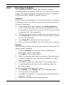
3.1.1
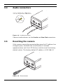
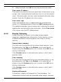
DC power connection
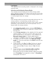
12
15
34
I/O
Lin
e
DC
12
V
-ou
Eth
t
Res
et
ern
et
Lin
e
-in
Figure 3.1
1.
DC power connection
Slide the plug adapter that matches your outlet socket
onto the supplied power supply.
2.
Insert the power connector jack from the power supply
into the DC12V socket of the camera.
3.
Connect the power supply to either a 230 VAC or a
120 VAC power supply outlet.
When power is supplied to the camera the LED on the bottomfront of the camera lights. (This LED can be disabled in the
Installer Options menu.)
Note:
The date/time must be synchronized each time after power on.
It is important to ensure that the date/time is correct for
recording. An incorrect date/time setting could prevent correct
recording.
Bosch Security Systems
Installation and Operation Manual
AR18-09-B003 | v1.1 | 2010.05
16
en | Installation
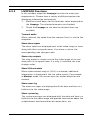
3.2
IP Camera 200 Series
Network (and power) connector
12
34
I/O
DC
Lin
e
12
-ou
V
t
Res
et
Eth
ern
et
Lin
e
-in
Figure 3.2
Network connection
–
Connect the camera to a 10/100 Base-T network.
–
Use a shielded UTP Category 5e cable with RJ45
connectors.
–
Power can be supplied to the camera via the Ethernet
cable compliant with the Power-over-Ethernet
(IEEE 802.3af) standard.
Note:
The camera can accept power from both the DC12V power
input and the Ethernet input at the same time. The primary
source is the DC12V input. If both are connected and DC power
removed, the camera will reboot and will then be powered by
PoE. If both are connected and the PoE removed, the camera
will continue working.
AR18-09-B003 | v1.1 | 2010.05
Installation and Operation Manual
Bosch Security Systems
IP Camera 200 Series
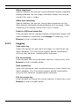
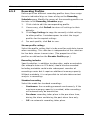
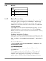
3.3
Installation | en
17
I/O connector
12
34
I/O
DC
I/O
12
Lin
e
-ou
V
t
Res
et
Eth
ern
et
Lin
e-in
5 mm
(0.2 in)
Pin 1
Figure 3.3
I/O connector pins
Function
Pin
I/O socket
Relay
1
Relay out contact 1
2
Relay out contact 2
Alarm input
–
Pin 4
3
Trigger in Positive
4
Trigger in Negative
Max. wire diameter AWG 22-28 for both stranded and
solid; cut back 5 mm (0.2 in) of insulation.
–
Relay output switching capability: Max. voltage 24 VAC or
24 VDC. Max. 1 A continuous, 12 VA.
–
Trigger in: +9 VDC minimum; +30 VDC maximum. Reverse
polarity connection will be inactive.
–
Alarm input configurable as active low or active high.
Bosch Security Systems
Installation and Operation Manual
AR18-09-B003 | v1.1 | 2010.05
18
en | Installation
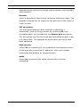
3.4
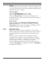
IP Camera 200 Series
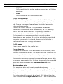
Audio connectors
Line in: 9 kOhm typ., 200 mVrms
Line out: 16 Ohm min. 200 mVrms
Line - L
GND
12
Line - R
34
I/O
DC
12
Lin
e-o
V
ut
Res
et
Eth
ern
et
Lin
e-in
Figure 3.4
Audio connectors
Connect audio devices to the Line In and Line Out connectors.
3.5
Resetting the camera
If the camera cannot be connected because the IP address has
changed, press and hold the reset button (7 seconds
approximately) until the LED flashes (red) to recall the factory
default values. The factory default IP address is 192.168.0.1
12
34
I/O
Lin
e-o
ut
DC
12
V
Res
et
Eth
ern
et
Lin
e-in
Figure 3.5
AR18-09-B003 | v1.1 | 2010.05
Reset button
Installation and Operation Manual
Bosch Security Systems
IP Camera 200 Series
3.6
Installation | en
19
SD card
Figure 3.6
SD card
1.
Unscrew the cover on the right side of the camera.
2.
Slide the SD card into the slot.
3.
Close and secure the cover.
The camera supports most SD/SDHC cards. For a list of
recommended cards (not supplied by Bosch), please visit
www.boschsecurity.com
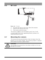
3.7
Mounting the camera
The camera can be mounted either from the top or from the
bottom (1/4"-20 UNC thread). The mounting socket is isolated
from ground to prevent ground loops.
CAUTION!
Do not point the camera/lens into direct sunlight as this may
damage the sensors.
Bosch Security Systems
Installation and Operation Manual
AR18-09-B003 | v1.1 | 2010.05
20
en | Installation
IP Camera 200 Series
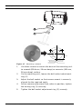
120°
27 mm
120°
3x Ø3.8 mm
D: 26 mm
Figure 3.7
1.
3x Ø6 mm
D: 26 mm
Mounting a camera
Use three screws to secure the base of the mounting unit
to a wood (Ø3.8 mm, 26 mm deep) or concrete (Ø6 mm,
26 mm deep) surface.
2.
On the mounting unit, loosen the ball-socket adjustment
ring (2).
3.
Adjust the ball-socket so that camera mount is correcrly
aligned for the required angle.
4.
Screw camera onto mount and, when in position, tighten
the locking ring (1) securely.
5.
Tighten the ball-socket adjustment ring (2) securely.
AR18-09-B003 | v1.1 | 2010.05
Installation and Operation Manual
Bosch Security Systems
IP Camera 200 Series
4
Browser connection | en
21
Browser connection
A computer with Microsoft Internet Explorer can be used to
receive live images from the camera, control cameras, and
replay stored sequences. The camera is configured over the
network using a browser or via the BVIP Lite Suite (supplied
with the product).
4.1
System requirements
–
–
Microsoft Internet Explorer version 7.0 or higher
Monitor: resolution at least 1024 × 768 pixels, 16 or 32 bit
color depth
–
Intranet or Internet network access
The Web browser must be configured to enable Cookies to be
set from the IP address of the unit.
In Windows Vista, deactivate protected mode on the Security
tab under Internet Options.
To play back live video images, an appropriate ActiveX must be
installed on the computer. If necessary, the required software
and controls can be installed from the product CD provided.
a.
Insert the CD into the CD-ROM drive of the computer.
If the CD does not start automatically, open the root
directory of the CD in Windows Explorer and double
click start.exe
b.
4.2
Follow the on-screen instructions.
Establishing the connection
The camera must be assigned a valid IP address to operate on
your network. The default address pre-set at the factory is
192.168.0.1
1.
Start the Web browser.
2.
Enter the IP address of the camera as the URL.
Bosch Security Systems
Installation and Operation Manual
AR18-09-B003 | v1.1 | 2010.05
22
en | Browser connection
IP Camera 200 Series
Note:
If the connection is not established, the maximum number of
possible connections may already have been reached.
Depending on the device and network configuration, up to 25
web browsers, or 50 VIDOS or Bosch VMS connections are
supported.
4.2.1
Password protection in camera
A camera offers the option of limiting access across various
authorization levels. If the camera is password-protected, a
message to enter the password appears.
1.
Enter the user name and the associated password in the
appropriate fields.
2.
Click OK. If the password is correct, the desired page is
displayed.
4.3
Protected network
If a Radius server is used for network access control (802.1x
authentication), the camera must be configured first. To
configure the camera for a Radius network, connect it directly
to a PC via a crossed network cable and configure the two
parameters, Identity and Password. Only after these have been
configured can communication with the camera via the network
occur.
AR18-09-B003 | v1.1 | 2010.05
Installation and Operation Manual
Bosch Security Systems
IP Camera 200 Series
4.4
Browser connection | en
23
Connection established
When a connection is established, the LIVEPAGE is initially
displayed. The application title bar displays the type number of
the connected camera and three items: LIVEPAGE,
RECORDINGS, SETTINGS.
Note:
The RECORDINGS link is only visible if a storage medium is
available.
Figure 4.1
4.4.1
Livepage
LIVEPAGE
The LIVEPAGE is used to display and control the video stream.
Refer to Section 7.1 Livepage, page 82 for more information.
4.4.2
RECORDINGS
Click RECORDINGS in the application title bar to open the
playback page. Refer to Section 7.2 Recordings page, page 85 for
more information.
4.4.3
SETTINGS
Click SETTINGS in the application title bar to configure the
camera and the application interface. A new page containing
Bosch Security Systems
Installation and Operation Manual
AR18-09-B003 | v1.1 | 2010.05
24
en | Browser connection
IP Camera 200 Series
the configuration menu is opened. All settings (except date/
time) are stored in the camera memory so that they are
retained, even if the power is interrupted.
Changes that influence the fundamental functioning of the unit
(for example, firmware updates) can only be made using the
configuration menu.
The configuration menu tree allows all parameters of the unit to
be configured. The configuration menu is divided into Basic
Mode and Advanced Mode.
Refer to Section 5 Basic Mode, page 25 for more information on
basic settings; refer to Section 6 Advanced Mode, page 30 for
more information on advanced settings.
Note:
It is recommended that only expert users or system
administrators use the Advanced Mode.
AR18-09-B003 | v1.1 | 2010.05
Installation and Operation Manual
Bosch Security Systems
IP Camera 200 Series
Basic Mode | en
5
Basic Mode
5.1
Basic Mode menu tree
25
The basic mode configuration menu allows a set of basic
camera parameters to be configured.
Basic Mode
>
Device Access
>
Date/Time
>
Network
>
Encoder Profile
>
Audio
>
Recording
>
System Overview
To view the current settings:
1.
If necessary, click the Basic Mode menu to expand it. The
sub-menus are displayed.
2.
Click a sub-menu. The corresponding page is opened.
The settings are changed by entering new values or by selecting
a pre-defined value in a list field.
Saving changes
After making changes in a window, click Set to send the new
settings to the device and save them there.
Clicking Set saves only the settings in the current window.
Changes in any other windows are ignored.
Click SETTINGS in the applications title bar to close the
window without saving the changes.
Note:
When entering names do not use any special characters, for
example &. Special characters are not supported by the internal
recording management system.
Bosch Security Systems
Installation and Operation Manual
AR18-09-B003 | v1.1 | 2010.05
26
en | Basic Mode
IP Camera 200 Series
5.2
Device Access
5.2.1
Camera name
The camera can be assigned a name to assist in identifying it.
The name simplifies the management of multiple devices in
more extensive systems.
The camera name is used for remote identification, for example,
in the event of an alarm. Enter a name that makes it as easy as
possible to identify the location unambiguously.
5.2.2
Password
A password prevents unauthorized access to the device. The
device recognizes three authorization levels: service, user, and
live.
–
service is the highest authorization level. Entering the
correct password gives access to all the functions of the
camera and allows all configuration settings to be
changed.
–
user is the middle authorization level. This user can
operate the device, play back recordings, and also control
a camera but cannot change the configuration.
–
live is the lowest authorization level. It can only be used to
view the live video image and switch between the different
live image displays.
Use the various authorization levels to limit access. Proper
password protection is only guaranteed if all higher
authorization levels are also protected with a password. For
example, if a live password is assigned, a service and a user
password should also be set. When assigning passwords,
always start from the highest authorization level, service, and
use different passwords.
Password
Define and change a separate password for each level while
logged in as service or if the device is not protected by a
password. Enter the password for the selected level.
AR18-09-B003 | v1.1 | 2010.05
Installation and Operation Manual
Bosch Security Systems
IP Camera 200 Series
Basic Mode | en
27
Confirm password
Re-enter the new password to ensure that there are no typing
mistakes.
The new password is only saved after clicking Set. Therefore,
click Set immediately after entering and confirming the
password, even if you plan to assign a password at another
level.
5.3
Date/Time
Device date, time and zone
If there are multiple devices operating in the system or
network, it is important to synchronize their internal clocks. For
example, it is only possible to identify and correctly evaluate
simultaneous recordings when all devices are operating on the
same time.
As the device time is controlled by the internal clock, it is not
necessary to enter the day or date of the week. These are set
automatically. The time zone in which the system is located is
also set automatically.
1.
Click Sync to PC to apply the system time from your
computer to the device.
Note:
It is important to ensure that the date/time is correct for
recording. An incorrect date/time setting could prevent correct
recording.
Bosch Security Systems
Installation and Operation Manual
AR18-09-B003 | v1.1 | 2010.05
28
en | Basic Mode
5.4
IP Camera 200 Series
Network
Use the settings on this page to integrate the device into a
network. Some changes only take effect after a reboot. In this
case, the Set button changes to Set and Reboot.
1.
Make the desired changes.
2.
Click Set and Reboot.
–
The device is rebooted and the changed settings are
activated. If the IP address, subnet mask, or gateway
address is changed, then the device is only available
under the new addresses after the reboot.
DHCP
If the network has a DHCP server for dynamic IP address
allocation, set this parameter to On to activate the automatic
acceptance of DHCP-assigned IP addresses.
Note:
Certain applications (for example, Bosch Video Management
System) use the IP address for the unique assignment of the
device. If using these applications, the DHCP server must
support the fixed assignment between IP address and MAC
address, and must be appropriately set up so that, once an IP
address is assigned, it is retained each time the system is
rebooted.
IP address
Enter the desired IP address for the camera. The IP address
must be valid for the network.
Subnet mask
Enter the appropriate subnet mask for the set IP address.
Gateway address
Enter the IP address of the gateway to establish a connection to
a remote location in a different subnet. Otherwise, this field can
remain empty (0.0.0.0).
AR18-09-B003 | v1.1 | 2010.05
Installation and Operation Manual
Bosch Security Systems
IP Camera 200 Series
5.5
Basic Mode | en
29
Encoder Profile
Select a profile for encoding the video signal. Pre-programmed
profiles are available that give priority to different parameters.
When a profile is selected, its details are displayed.
Main frequency and Operation environment
Select 50 Hz or 60 Hz as the main frequency, and Indoor or
Outdoor for the operation environment.
5.6
Audio
Switch the camera audio On or Off.
5.7
Recording
Record the images from the camera to a storage medium. For
long-term authoritative images, it is essential to use a
Divar 700 Series Digital Video Recorder or an appropriately
sized iSCSI system.
5.7.1
5.8
Storage medium
1.
Select the required storage medium from the list.
2.
Click Start to start recording or Stop to end recording.
System Overview
This page provides general information on the hardware and
firmware system, including version numbers. No items can be
changed on this page but they can be copied for information
purposes when troubleshooting.
Bosch Security Systems
Installation and Operation Manual
AR18-09-B003 | v1.1 | 2010.05
30
en | Advanced Mode
IP Camera 200 Series
6
Advanced Mode
6.1
Advanced Mode menu tree
The advanced mode configuration menu contains all camera
parameters that can be configured.
Advanced Mode
>
General
>
Web Interface
>
Camera
>
Recording
>
Alarm
>
Interfaces
>
Network
>
Service
To view the current settings:
1.
Click the Advanced Mode menu to expand it. The
2.
Click a menu sub-heading to expand it.
3.
Click a sub-menu. The corresponding page is opened.
associated menu sub-headings are displayed.
The settings are changed by entering new values or by selecting
a pre-defined value in a list field.
Saving changes
After making changes in a window, click Set to send the new
settings to the device and save them there.
Clicking Set saves only the settings in the current window.
Changes in any other windows are ignored.
Click SETTINGS in the applications title bar to close the
window without saving the changes made.
Note:
When entering names do not use any special characters, for
example &. Special characters are not supported by the internal
recording management system.
AR18-09-B003 | v1.1 | 2010.05
Installation and Operation Manual
Bosch Security Systems
IP Camera 200 Series
6.2
Advanced Mode | en
31
General
General
6.2.1
>
Identification
>
Password
>
Date/Time
>
Display Stamping
Identification
Camera ID
Each camera should be assigned a unique identifier that can be
entered here as an additional means of identification.
Camera name
Assign a camera name to assist in identifying it. The name
simplifies the management of multiple devices in more
extensive systems, for example the VIDOS or Bosch VMS
software. The camera name is used for remote identification,
for example, in the event of an alarm. Enter a name that makes
it as easy as possible to identify the location unambiguously.
Initiator extension
Add text to an initiator name to make identification easier in
large iSCSI systems. This text is added to the initiator name,
separated from it by a full stop.
6.2.2
Password
A password prevents unauthorized access to the device. The
device recognizes three authorization levels: service, user, and
live.
–
service is the highest authorization level. Entering the
correct password gives access to all the functions of the
camera and allows all configuration settings to be
changed.
–
user is the middle authorization level. This user can
operate the device, play back recordings, and also control
a camera but cannot change the configuration.
Bosch Security Systems
Installation and Operation Manual
AR18-09-B003 | v1.1 | 2010.05
32
en | Advanced Mode
–
IP Camera 200 Series
live is the lowest authorization level. It can only be used to
view the live video image and switch between the different
live image displays.
Use the various authorization levels to limit access. Proper
password protection is only guaranteed if all higher
authorization levels are also protected with a password. For
example, if a live password is assigned, a service and a user
password should also be set. When assigning passwords,
always start from the highest authorization level, service, and
use different passwords.
Password
Define and change a separate password for each level while
logged in as service or if the device is not protected by a
password. Enter the password for the selected level.
Confirm password
Re-enter the new password to ensure that there are no typing
mistakes.
The new password is only saved after clicking Set. Therefore,
click Set immediately after entering and confirming the
password, even if assigning a password at another level.
6.2.3
Date/Time
Date format
Select the required date format.
Device date / Device time
If there are multiple devices operating in your system or
network, it is important to synchronize their internal clocks. For
example, it is only possible to identify and correctly evaluate
simultaneous recordings when all devices are operating on the
same time.
1.
Enter the current date. Since the device time is controlled
by the internal clock, it is not necessary to enter the day of
the week – it is added automatically.
AR18-09-B003 | v1.1 | 2010.05
Installation and Operation Manual
Bosch Security Systems
IP Camera 200 Series
2.
Advanced Mode | en
33
Enter the current time or click Sync to PC to apply the
system time from your computer to the device.
Note:
It is important to ensure that the date/time is correct for
recording. An incorrect date/time setting could prevent correct
recording.
Device time zone
Select the time zone in which the system is located.
Daylight saving time
The internal clock can switch automatically between normal
and daylight saving time (DST). The device already contains the
data for DST switch-overs up to the year 2015. Use this data or
create alternative time saving data, if required.
Note:
If a table is not created, there is no automatic switching. When
editing the table, note that values occur in linked pairs (DST
start and end dates).
First, check the time zone setting. If it is not correct, select the
appropriate time zone for the system:
1.
2.
Click Set.
Click Details. A new window opens showing an empty
table.
3.
Click Generate to fill the table with the preset values from
the camera.
4.
Select the region or the city which is closest to the
system's location from the list box below the table.
5.
Click one of the entries in the table to make changes. The
entry is highlighted.
6.
7.
Click Delete to remove the entry from the table.
Choose other values from the list boxes under the table, to
change the selected entry. Changes are immediate.
8.
If there are empty lines at the bottom of the table, for
example after deletions, add new data by marking the row
and selecting values from the list boxes.
Bosch Security Systems
Installation and Operation Manual
AR18-09-B003 | v1.1 | 2010.05
34
en | Advanced Mode
9.
IP Camera 200 Series
When finished, click OK to save and activate the table.
Time server IP address
The camera can receive the time signal from a time server using
various time server protocols and then use it to set the internal
clock. The device polls the time signal automatically once every
minute. Enter the IP address of a time server.
Time server type
Select the protocol that is supported by the selected time
server. It is recommended to select the SNTP server protocol.
This protocol provides high accuracy and is required for special
applications and future function extensions. Select Time server
if the server uses the RFC 868 protocol.
6.2.4
Display Stamping
Various overlays or stamps in the video image provide
important supplementary information. These overlays can be
enabled individually and arranged on the image in a clear
manner.
Camera name stamping
This field sets the position of the camera name overlay. It can
be displayed at the Top, at the Bottom, or at a position of
choice using the Custom option, or it can be set to Off for no
overlay information.
If the Custom option is selected, enter values in the X and Y
position fields.
Time stamping
This field sets the position of the time and date overlay. It can
be displayed at the Top, at the Bottom, or at a position of
choice using the Custom option, or it can be set to Off for no
overlay information.
If the Custom option is selected, enter values in the X and Y
position fields.
Display milliseconds
If necessary, display milliseconds for Time stamping. This
information can be useful for recorded video images; however,
AR18-09-B003 | v1.1 | 2010.05
Installation and Operation Manual
Bosch Security Systems
IP Camera 200 Series
Advanced Mode | en
35
it does increase the processor's computing time. Select Off if
displaying milliseconds is not needed.
Alarm mode stamping
Select On for a text message to be overlaid in the event of an
alarm. It can be displayed at a position of choice using the
Custom option, or it can be set to Off for no overlay
information.
If the Custom option is selected, enter values in the X and Y
position fields.
Alarm message
Enter the message to be displayed on the image in the event of
an alarm. The maximum text length is 31 characters.
Video watermarking
Select On for the transmitted video images to be watermarked.
After activation, all images are marked with a green W. A red W
indicates that the sequence (live or saved) has been
manipulated.
Bosch Security Systems
Installation and Operation Manual
AR18-09-B003 | v1.1 | 2010.05
36
en | Advanced Mode
6.3
IP Camera 200 Series
Web Interface
Web Interface
6.3.1
>
Appearance
>
LIVEPAGE Functions
>
Logging
Appearance
Adapt the appearance of the web interface and change the
website language to meet your requirements. If necessary,
replace the company's logo (top right) and the device name
(top left) in the top part of the window with individual graphics.
Either GIF or JPEG images can be used. The file paths must
correspond to the access mode (for example,
C:\Images\Logo.gif for access to local files or http://
www.myhostname.com/images/logo.gif for access via the
Internet/Intranet). For access via the Internet/Intranet, there
must be a connection in order to display the image. The image
files are not stored on the camera.
To restore the original graphics, delete the entries in the
Company logo and Device logo fields.
Website language
Select the language for the user interface here.
Company logo
Enter the path to a suitable image in this field. The image can
be stored on a local computer, a local network, or at an Internet
address.
Note:
When the image was stored on a local computer, it can only be
displayed by this local computer.
Device logo
Enter the path for a suitable image for the device logo in this
field. The image can be stored on a local computer, a local
network, or at an Internet address.
AR18-09-B003 | v1.1 | 2010.05
Installation and Operation Manual
Bosch Security Systems
IP Camera 200 Series
6.3.2
Advanced Mode | en
37
LIVEPAGE Functions
In this window, adapt the Livepage functions to meet your
requirements. Choose from a variety of different options for
displaying information and controls.
1.
Mark the check boxes for the functions to be displayed on
the Livepage. The selected elements are checked.
2.
Check the Livepage to see how the desired items are
available.
Transmit audio
When selected, the audio from the camera (if on) is sent to the
computer.
Show alarm inputs
The alarm inputs are displayed next to the video image as icons
along with their assigned names. If an alarm is active, the
corresponding icon changes color.
Show relay outputs
The relay output is shown next to the video image as an icon
along with its assigned name. If a relay is switched, the icon
changes color.
Show VCA metadata
When video content analysis (VCA) is activated, additional
information is displayed in the live video stream. For example,
in Motion+ mode, the sensor areas for motion detection are
marked.
Show event log
The event messages are displayed with the date and time in a
field next to the video image.
Show system log
The system messages are displayed with the date and time in a
field next to the video image and provide information about the
establishment and termination of connections, etc.
Bosch Security Systems
Installation and Operation Manual
AR18-09-B003 | v1.1 | 2010.05
38
en | Advanced Mode
IP Camera 200 Series
Allow snapshots
Specify whether the icon for saving individual images should be
displayed below the live image. Individual images can only be
saved if this icon is visible.
Allow local recording
Specify whether the icon for saving video sequences on the
local memory should be displayed below the live image. Video
sequences can only be saved if this icon is visible.
Path for JPEG and video files
Enter the path for the storage location of individual images and
video sequences saved from the Livepage. If necessary, click
Browse to find a suitable folder.
6.3.3
Logging
Save event log
Select this option to save event messages in a text file on the
local computer. This file can be viewed, edited, and printed
with any text editor or standard office software.
File for event log
Enter the path for saving the event log here. If necessary, click
Browse to find a suitable folder.
Save system log
Select this option to save system messages in a text file on the
local computer. This file can be viewed, edited, and printed
with any text editor or standard office software.
File for system log
Enter the path for saving the system log here. If necessary, click
Browse to find a suitable folder.
AR18-09-B003 | v1.1 | 2010.05
Installation and Operation Manual
Bosch Security Systems
IP Camera 200 Series
6.4
Advanced Mode | en
39
Camera
Camera
6.4.1
>
Encoder Profile
>
Encoder Streams
>
Video
>
Audio
>
Installer Options
Encoder Profile
Adapt the video data transmission to the operating environment
(network structure, bandwidth, data structures). The camera
simultaneously generates two H.264 video streams and an
M-JPEG stream (Tri-streaming). Select the compression
settings of these streams individually, for example, one setting
for transmissions to the Internet and one for LAN connections.
The settings are made individually for each stream.
Define profiles
Eight definable profiles are available. The pre-programmed
profiles give priority to different parameters.
–
High resolution 1
VGA resolution with low delay
–
High resolution 2
VGA resolution with lower data rate
–
Low bandwidth
VGA resolution for low bandwidth connections
–
DSL
VGA resolution for DSL connections at 500 kbps maximum
–
ISDN (2B)
QVGA resolution for ISDN connections at 100 kbps
maximum
–
ISDN (1B)
QVGA resolution for ISDN connections at 50 kbps
maximum
Bosch Security Systems
Installation and Operation Manual
AR18-09-B003 | v1.1 | 2010.05
40
en | Advanced Mode
–
IP Camera 200 Series
MODEM
QVGA resolution for analog modem connections at 22 kbps
maximum
–
GSM
QVGA resolution for GSM connections
Profile Configuration
Profiles can be configured for use with the H.264 settings of
encoder streams. Select a profile by clicking the appropriate
tab. Change the name of a profile and individual parameter
values within a profile.
Profiles are rather complex. They include a number of
parameters that interact with one another, so it is generally
best to use the default profiles. Only change a profile if
completely familiar with all the configuration options.
The parameters as a group constitute a profile and are
dependent on one another. If a setting outside the permitted
range for a parameter is entered, the nearest valid value is
substituted when the settings are saved.
Profile name
Enter a new name for the profile here.
Target data rate
To optimize utilization of the bandwidth in the network, limit
the data rate for the camera. The target data rate should be set
according to the desired picture quality for typical scenes with
no excessive motion.
For complex images or frequent changes of image content due
to frequent movements, this limit can temporarily be exceeded
up to the value entered in the Maximum data rate field.
Maximum data rate
This maximum data rate is not exceeded under any
circumstances. Depending on the video quality settings for the
I-frames and P-frames, this can result in individual images being
skipped.
The value entered here must be at least 10% higher than the
value entered in the Target data rate field. If the value entered
AR18-09-B003 | v1.1 | 2010.05
Installation and Operation Manual
Bosch Security Systems
IP Camera 200 Series
Advanced Mode | en
41
here is too low, it is automatically adjusted.
Encoding interval
The Encoding interval slider determines the interval at which
images are encoded and transmitted. This can be particularly
advantageous with low bandwidths. The image rate in ips
(images per second) is displayed next to the slider.
Video resolution
Select here the desired resolution for the video image. VGA
(640x480) and QVGA (320x240) resolutions are available.
Expert Settings
if necessary, use the expert settings to adapt the I-frame quality
and the P-frame quality to specific requirements. The setting is
based on the H.264 quantization parameter (QP).
I-frame quality
This setting adjusts the image quality of the I-frames. The basic
setting Auto automatically adjusts the quality to the settings for
the P-frame video quality. Alternatively, use the slider to set a
value between 9 and 51. The value 9 represents the best image
quality with, if necessary, a lower frame refresh rate depending
on the settings for the maximum data rate. A value of 51 results
in a very high refresh rate and lower image quality.
P-frame quality
This setting adjusts the maximum image quality of the P-frames.
The basic setting Auto automatically adjusts to the optimum
combination of movement and image definition (focus).
Alternatively, use the slider to set a value between 9 and 51.
The value 9 represents the best image quality with, if necessary,
a lower frame refresh rate depending on the settings for the
maximum data rate. A value of 51 results in a very high refresh
rate and lower image quality.
Default
Click Default to return the profile to the factory default values.
Bosch Security Systems
Installation and Operation Manual
AR18-09-B003 | v1.1 | 2010.05
42
en | Advanced Mode
6.4.2
IP Camera 200 Series
Encoder Streams
Select H.264 Settings
1.
Select the codec algorithm for streams 1 and 2. The
following algorithms are available
2.
–
H.264 BP+ (HW decoder)
–
H.264 MP Low Latency
Select the default profile for streams 1 and 2 from the
eight profiles that have been defined.
The algorithm properties have the following settings:
H.264 BP+
H.264 MP
(HW decoder)
Low Latency
CABAC
off
on
CAVLC
on
off
GOP structure
IP
IP
I-frame distance
15
30
Deblocking filter
on
on
Recommended for
Hardware
Software decoders,
decoders,
PTZ and rapid
Divar 700 Series
image movements
Preview >>
Previews of streams 1 and 2 can be shown.
1.
Click Preview >> to display a preview of the video for
streams 1 and 2. the current profile is shown above the
preview.
2.
Click 1:1 Live View below a preview to open a viewing
window for that stream. Various additional items of
information are shown across the top of the window.
3.
Click Preview << to close the preview displays.
Note:
Deactivate the display of the video images if the performance of
the computer is adversely affected by the decoding of the data
stream.
AR18-09-B003 | v1.1 | 2010.05
Installation and Operation Manual
Bosch Security Systems
IP Camera 200 Series
Advanced Mode | en
43
JPEG stream
Set the parmeters for the M-JPEG stream.
–
–
Select the Max. frame rate in images per second (IPS).
The Picture quality slider allows adjustment of the MJPEG image quality from Low to High.
Note:
The JPEG resolution follows the highest resolution setting
either in stream 1 or stream 2. For example, if stream 1 is VGA
and stream 2 is QVGA, the JPEG resolution will be VGA.
6.4.3
Video
Contrast (0...255)
Adjusts the contrast of the image.
Saturation (0...255)
Adjusts the color saturation; 0 gives a monochrome image.
Brightness (0...255)
Adjusts the brightness of the image..
White balance
–
ATW: Auto tracking white balance allows the camera to
continually adjust for optimal color reproduction.
–
In Manual mode the Red, Green, and Blue gain can be
manually set to a desired position.
Apply white balance: Hold puts the ATW on hold and saves the
color settings.
R-gain
The red gain adjustment offsets the factory white point
alignment (reducing red introduces more cyan).
G-gain
The green gain adjustment offsets the factory white point
alignment to optimize the white point.
B-gain
The blue gain adjustment offsets the factory white point
alignment (reducing blue introduces more yellow).
Bosch Security Systems
Installation and Operation Manual
AR18-09-B003 | v1.1 | 2010.05
44
en | Advanced Mode
IP Camera 200 Series
It is only necessary to change the white point offset for special
scene conditions.
Main frequency and Operation environment
Select 50 Hz or 60 Hz as the main frequency, and Indoor or
Outdoor for the operation environment.
Exposure/frame rate
–
Auto exposure/frame rate: the camera automatically sets
the framerate. The camera tries to maintain the selected
default shutter speed as long as the light level of the scene
permits.
Select a minimum frame rate from 4 to 30 fps.
–
Fixed exposure: allows a user-defined shutter time.
Select the shutter speed when exposure control is set to
fixed (1/30, 1/50, 1/60, 1/100, 1/120, 1/250, 1/500, 1/
1000, 1/2500, 1/5000, 1/7500, or 1/15000).
Note:
Shutter time is affected by frame rate in auto framerate mode.
For example, if the frame rate is 30 IPS, the longest shutter
time available is 1/30s.
Default
Click Default to set all video values to their factory setting.
6.4.4
Audio
Select the microphone or line-in connector as the Audio input
or switch it off. Adust the Input volume with the slider.
Switch the Audio output On or Off.
6.4.5
Installer Options
Disable the Camera LED on the camera to switch it off.
Enable Mirror image to obtain a mirror image display of the
camera picture.
AR18-09-B003 | v1.1 | 2010.05
Installation and Operation Manual
Bosch Security Systems
IP Camera 200 Series
6.5
Advanced Mode | en
45
Recording
Recording
>
Storage Management
>
Recording Profiles
>
Retention Time
>
Recording Scheduler
>
Recording Status
Record the images from the camera to local storage media or to
an appropriately configured iSCSI system.
SDHC cards are the ideal solution for shorter storage times and
temporary recordings, for example, local buffering in the event
of network interruptions.
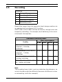
Continuous Recording Hours
SDHC card capacity
Profiles
High resolution 1 (VGA, 30F/S,
4 GB
8 GB
16 GB 32 GB
4h
8h
16 h
32 h
11 h
22 h
44 h
88 h
19 h
38 h
76 h
152h
78 h
156 h
312 h
624 h
H.264 MP, T:2000Kb,
M:4000Kb)
Low bandwidth (VGA, 30F/S,
H.264 MP, T:700Kb,
M:1500Kb)
DSL (VGA, 30F/S, H.264 MP,
T:400Kb, M:500Kb)
ISDN (2B) (VGA, 30F/S, H.264
MP, T:80Kb, M:100Kb)
Note:
The recording hours table is only an indication for reference, an
actual situation might be different (because of different scenes
or networking status for example).
Bosch Security Systems
Installation and Operation Manual
AR18-09-B003 | v1.1 | 2010.05
46
en | Advanced Mode
IP Camera 200 Series
For long-term authoritative images use an appropriately sized
iSCSI system.
A Video Recording Manager (VRM) can control all recording
when accessing an iSCSI system. The VRM is an external
program for configuring recording tasks for video servers. For
further information, contact your local customer service at
Bosch Security Systems.
6.5.1
Storage Management
Device manager
If the VRM option is activated, the VRM Video Recording
Manager manages all recording and no further settings can be
configured here.
Note:
Activating or deactivating VRM causes the current settings to be
lost; they can only be restored through reconfiguration.
Recording media
Select the required recording media to activate them and then
configure the recording parameters.
iSCSI Media
If an iSCSI system is selected as the storage medium, a
connection to the desired iSCSI system is needed to set the
configuration parameters.
The storage system selected must be available on the network
and completely set up. Amongst other things, it must have an IP
address and be divided into logical drives (LUN).
1.
Enter the IP address of the required iSCSI destination in
2.
If the iSCSI destination is password protected, enter this
3.
Click the Read button. The connection to the IP address is
the iSCSI IP address field.
into the Password field.
established. The Storage overview field displays the
logical drives.
AR18-09-B003 | v1.1 | 2010.05
Installation and Operation Manual
Bosch Security Systems
IP Camera 200 Series
Advanced Mode | en
47
Local Media
The supported local recording media is displayed in the storage
overview field.
Activating and Configuring Storage Media
The storage overview displays the available storage media.
Select individual media or iSCSI drives and transfer these to the
Managed storage media list. Activate the storage media in this
list and configure them for storage.
Note:
Each storage medium can only be associated with one user. If a
storage medium is already being used by another user,
decouple the user and connect the drive to the camera. Before
decoupling, make absolutely sure that the previous user no
longer needs the storage medium.
1.
In the Recording media section, click the iSCSI Media or
Local Media tab to display the applicable storage media in
the overview.
2.
In the Storage overview section, double-click the required
storage medium, a SD card, an iSCSI LUN or one of the
other available drives. The medium is then added to the
Managed storage media list. Newly added media is
indicated in the Status column by the status Not active.
3.
Click Set to activate all media in the Managed storage
media list. These are indicated in the Status column by the
status Online.
4.
Check the box in the Rec. 1 or Rec. 2 column to specify
which data stream should be recorded on the storage
media selected. Rec. 1 stores stream 1, Rec. 2 stores
stream 2.
5.
Check the boxes for the Overwrite older recordings
option to specify which older recordings can be
overwritten once the available memory capacity has been
used. Recording 1 corresponds to stream 1, Recording 2
corresponds to stream 2.
Bosch Security Systems
Installation and Operation Manual
AR18-09-B003 | v1.1 | 2010.05
48
en | Advanced Mode
IP Camera 200 Series
Note:
If older recordings are not allowed to be overwritten when the
available memory capacity has been used, the recording in
question is stopped. Specify limitations for overwriting old
recordings by configuring the retention time.
Formatting Storage Media
Delete all recordings on a storage medium at any time. Check
the recordings before deleting and back up important
sequences on the computer's hard drive.
1.
Click a storage medium in the Managed storage media list
to select it.
2.
Click Edit below the list. A new window opens.
3.
Click Formatting to delete all recordings in the storage
medium.
4.
Click OK to close the window.
Deactivating Storage Media
Deactivate any storage medium from the Managed storage
media list. It is then no longer used for recordings.
1.
Click a storage medium in the Managed storage media list
2.
Click Remove below the list. The storage medium is
to select it.
deactivated and removed from the list.
AR18-09-B003 | v1.1 | 2010.05
Installation and Operation Manual
Bosch Security Systems
IP Camera 200 Series
6.5.2
Advanced Mode | en
49
Recording Profiles
Define up to ten different recording profiles here, then assign
these to individual days or times of day on the Recording
Scheduler page. Modify the names of the recording profiles on
the tabs in the Recording Scheduler page.
1.
2.
Click a tab to edit the corresponding profile.
If necessary, click Default to return all settings to their
defaults.
3.
Click Copy Settings to copy the currently visible settings
to other profiles. A window opens to select the target
profiles for the copied settings.
4.
For each profile, click Set to save.
Stream profile settings
Select the profile setting that is to be used for each data stream
when recording. This selection is independent of the selection
for live data stream transmission. (The properties of the
profiles are defined on the Encoder Profile page.)
Recording includes
Specify whether, in addition to video data, audio or metadata
(for example alarms or VCA data) should also be recorded.
Including metadata could make subsequent searches of
recordings easier but it requires additional memory capacity.
Without metadata, it is not possible to include video content
analysis in recordings.
Standard recording
Select the mode for standard recordings:
–
Continuous: the recording proceeds continuously. If the
maximum memory capacity is reached, older recordings
will automatically be overwritten.
–
Pre-alarm: recording takes place in the pre-alarm time,
during the alarm and during the post-alarm time only.
–
Off: no automatic recording takes place.
Bosch Security Systems
Installation and Operation Manual
AR18-09-B003 | v1.1 | 2010.05
50
en | Advanced Mode
IP Camera 200 Series
Stream
Select the data stream to be used for standard recordings. (You
can select the data stream for alarm recordings separately and
independently of this setting.)
Alarm recording
Select the Pre-alarm time from the list box.
Select the Post-alarm time from the list box.
Select the Alarm stream to use for alarm recording. The
encoding interval for alarm recording can be selected from the
predefined profiles.
Alarm triggers
Select the alarm type (Alarm input/ Motion/Audio alarm /
Video loss alarm) that is to trigger a recording. Select the
Virtual alarm sensors that are to trigger a recording, via RCP+
commands or alarm scripts, for example.
6.5.3
Retention Time
Specify the retention times for recordings. If the available
memory capacity of a medium has been used, older recordings
are only overwritten if the retention time entered here has
expired.
Make sure that the retention time corresponds with the
available memory capacity. A rule of thumb for the memory
requirement is as follows: 1 GB per hour retention time with
VGA for complete frame rate and high image quality.
Enter the required retention time in hours or days for each
recording. Recording 1 corresponds to Stream 1, Recording 2
corresponds to Stream 2.
AR18-09-B003 | v1.1 | 2010.05
Installation and Operation Manual
Bosch Security Systems
IP Camera 200 Series
6.5.4
Advanced Mode | en
51
Recording Scheduler
The recording scheduler allows you to link the created
recording profiles to the days and times at which the camera's
images are to be recorded in the event of an alarm. Schedules
can be defined for weekdays and for holidays.
Weekdays
Assign as many time periods (in 15-minute intervals) as needed
for any day of the week. Move the mouse cursor over the table —
the time is displayed.
1.
Click the profile to be assigned in the Time periods box.
2.
Click a field in the table and, while holding down the left
mouse button, drag the cursor across all of the fields to be
assigned to the selected profile.
3.
4.
Use the right mouse button to deselect any of the intervals.
Click Select All to select all of the intervals to be assigned
to the selected profile.
5.
Click Clear All to deselect all of the intervals.
6.
When finished, click Set to save the settings to the device.
Holidays
Define holidays whose settings will override the settings for the
normal weekly schedule.
1.
Click the Holidays tab. Days that have already been
defined are shown in the table.
2.
Click Add. A new window opens.
3.
Select the desired date from the calendar. Drag the mouse
to select a range of dates. These are handled as a single
entry in the table.
4.
5.
Click OK to accept the selection(s). The window closes.
Assign the defined holidays to the recording profile as
described above.
Delete user-defined holidays at any time.
1.
Click Delete in the Holidays tab. A new window opens.
2.
Click the date to be deleted.
3.
Click OK. The selection is removed from the table and the
window is closed.
4.
Repeat for any other dates to be deleted.
Bosch Security Systems
Installation and Operation Manual
AR18-09-B003 | v1.1 | 2010.05
52
en | Advanced Mode
IP Camera 200 Series
Profile names
Change the names of the recording profiles listed in the Time
periods box.
1.
Click a profile.
2.
Click Rename.
3.
Enter the new name and click Rename again.
Activate recording
After completing configuration, activate the recording schedule
and start recording. Once activated, the Recording Profiles and
the Recording Scheduler are deactivated and the configuration
cannot be modified. Terminate recording at any time to modify
the configuration.
1.
Click Start to activate the recording schedule.
2.
Click Stop to deactivate the recording schedule.
Recordings that are currently running are interrupted and
the configuration can be modified.
Recording status
The graphic indicates the recording activity. An animated
graphic is seen when recording is taking place.
6.5.5
Recording Status
Details of the recording status are displayed here for
information. These settings cannot be changed.
AR18-09-B003 | v1.1 | 2010.05
Installation and Operation Manual
Bosch Security Systems
IP Camera 200 Series
6.6
Advanced Mode | en
53
Alarm
Alarm
6.6.1
>
Alarm Connections
>
VCA
>
Audio Alarm
>
Alarm E-Mail
Alarm Connections
Select the response of the camera when an alarm occurs. In the
event of an alarm, the device can automatically connect to a
pre-defined IP address. The device can contact up to ten IP
addresses in the order listed until a connection is established.
Connect on alarm
Select On so that the camera automatically connects to a predefined IP address in the event of an alarm. Select Follows
input 1 so that the device maintains the connection for as long
as an alarm exists.
Number of destination IP address
Specify the numbers of the IP addresses to be contacted in the
event of an alarm. The device contacts the remote locations one
after the other in the numbered sequence until a connection is
made.
Destination IP address
For each number, enter the corresponding IP address for the
desired remote station.
Destination password
If the remote station is password protected, enter the
password here.
Only ten passwords can be defined here. Define a general
password if more than ten connections are required, for
example, when connections are initiated by a controlling
system such as VIDOS or Bosch Video Management System.
Bosch Security Systems
Installation and Operation Manual
AR18-09-B003 | v1.1 | 2010.05
54
en | Advanced Mode
IP Camera 200 Series
The camera connects to all remote stations protected by the
same general password. To define a general password:
1.
Select 10 in the Number of destination IP address list
box.
2.
Enter 0.0.0.0 in the Destination IP address field.
3.
Enter the password in the Destination password field.
4.
Set the user password of all the remote stations to be
accessed using this password.
Setting destination 10 to the IP-address 0.0.0.0 overrides its
function as the tenth address to try.
Video transmission
If the device is operated behind a firewall, select TCP (HTTP
port) as the transfer protocol. For use in a local network, select
UDP.
Please note that in some circumstances, in the event of an
alarm, a larger bandwidth must be available on the network for
additional video images (if Multicast operation is not possible).
To enable Multicast operation, select the UDP option for the
Video transmission parameter here and on the Network page.
Remote port
Select a browser port, depending on the network configuration.
The ports for HTTPS connections are only available if the On
option in SSL encryption is selected.
Video output
If it is known which device is being used as the receiver, select
the analog video output to which the signal should be switched.
If the destination device is unknown, it is advisable to select the
First available option. In this case, the image is placed on the
first free video output. This is an output on which there is no
signal. The connected monitor only displays images when an
alarm is triggered. If a particular video output is selected and a
split image is set for this output on the receiver, select the
decoder from Decoder in the receiver that is to be used to
display the alarm image. Refer to the destination device
AR18-09-B003 | v1.1 | 2010.05
Installation and Operation Manual
Bosch Security Systems
IP Camera 200 Series
Advanced Mode | en
55
documentation concerning image display options and available
video outputs.
Decoder
Select a decoder of the receiver to display the alarm image. The
decoder selected has an impact on the position of the image in
a split screen.
SSL encryption
SSL encryption protects data used for establishing a
connection, such as the password. By selecting On, only
encrypted ports are available for the Remote port parameter.
SSL encryption must be activated and configured on both sides
of a connection. The appropriate certificates must also have
been uploaded.
Auto-connect
Select On to automatically re-established a connection to one
of the previously specified IP addresses after each reboot,
connection breakdown, or network failure.
Audio
Select On to transmit the audio stream with an alarm
connection.
Bosch Security Systems
Installation and Operation Manual
AR18-09-B003 | v1.1 | 2010.05
56
en | Advanced Mode
6.6.2
IP Camera 200 Series
Video Content Analyses (VCA)
The camera has integrated VCA which can detect and analyze
changes in the signal using image processing algorithms. Such
changes can be due to movements in the camera's field of view.
Select various VCA configurations and adapt these to your
application, as required. The Silent MOTION+ configuration is
active by default. In this configuration, metadata is created to
facilitate searches of recordings, however, no alarm is
triggered.
1.
Select a VCA configuration and make the required settings.
2.
If necessary, click the Default button to return all settings
to their default values.
Note:
If there is not enough computing power, priority is given to live
images and recordings. This can lead to impairment of the VCA
system. Observe the processor load and optimize the encoder
settings or the VCA settings if necessary, or turn off VCA
completely.
AR18-09-B003 | v1.1 | 2010.05
Installation and Operation Manual
Bosch Security Systems
IP Camera 200 Series
6.6.3
Advanced Mode | en
57
VCA configuration- Profiles
Configure two profiles with different VCA configurations. Save
profiles on your computer's hard drive and load saved profiles
from there. This can be useful if testing a number of different
configurations. Save a functioning configuration and test new
settings. Use the saved configuration to restore the original
settings at any time.
1.
2.
Select a VCA profile and enter the required settings.
If necessary, click Default to return all settings to default
values.
3.
Click the Save... to save the profile settings to another file.
A new window opens in which to specify the file name and
where to save it.
4.
Click Load... to load a saved profile. A new window opens
in which to select the profile file and specify where to save
the file.
To rename a profile:
1.
To rename the file, click the icon to the right of the list field
and enter the new profile name in the field.
2.
Click the icon again. The new profile name is saved.
The current alarm status is displayed for information purposes.
Aggregation time (s)
Set an aggregation time of between 0 and 20 seconds. The
aggregation time always starts when an alarm event occurs. It
extends the alarm event by the value set. This prevents alarm
events that occur in quick succession from triggering several
alarms and successive events in a rapid sequence. No further
alarm is triggered during the aggregation time.
The post-alarm time set for alarm recordings only starts once
the aggregation time has expired.
Analysis type
Select the required analysis algorithm. By default, only Motion+
is available — this offers a motion detector and essential
recognition of tampering.
Bosch Security Systems
Installation and Operation Manual
AR18-09-B003 | v1.1 | 2010.05
58
en | Advanced Mode
IP Camera 200 Series
Metadata is always created for a video content analysis, unless
this was explicitly excluded. Depending on the analysis type
selected and the relevant configuration, additional information
overlays the video image in the preview window next to the
parameter settings. With the Motion+ analysis type, for
example, the sensor fields in which motion is recorded are
marked with rectangles.
Motion detector
Motion detection is available for the Motion+ analysis type. For
the detector to function, the following conditions must be met:
–
Analysis must be activated.
–
At least one sensor field must be activated.
–
The individual parameters must be configured to suit the
operating environment and the desired responses.
–
The sensitivity must be set to a value greater than zero.
Note:
Reflections of light (from glass surfaces, etc.), lights switching
on and off, or changes in the light level caused by cloud
movement on a sunny day can trigger unintended responses
from the motion detector and generate false alarms. Run a
series of tests at different times of the day and night to ensure
that the video sensor is operating as intended. For indoor
surveillance, ensure constant lighting of the areas during the
day and at night.
Sensitivity
Sensitivity is available for the Motion+ analysis type. The basic
sensitivity of the motion detector can be adjusted for the
environmental conditions to which the camera is subject. The
sensor reacts to variations in the brightness of the video image.
The darker the observation area, the higher the value that must
be selected.
Minimum object size
Specify the number of sensor fields that a moving object must
cover to generate an alarm. This setting prevents objects that
are too small from triggering an alarm. A minimum value of 4 is
AR18-09-B003 | v1.1 | 2010.05
Installation and Operation Manual
Bosch Security Systems
IP Camera 200 Series
Advanced Mode | en
59
recommended. This value corresponds to four sensor fields.
Debounce time 1 s
The debounce time prevents very brief alarm events from
triggering individual alarms. If the Debounce time 1 s option is
activated, an alarm event must last at least 1 second to trigger
an alarm.
Selecting the area
Select the areas of the image to be monitored by the motion
detector. The video image is subdivided into square sensor
fields. Activate or deactivate each of these fields individually. To
exclude particular regions of the camera's field of view from
monitoring due to continuous movement (by a tree in the wind,
for example), the relevant fields can be deactivated.
1.
Click Select Area to configure the sensor fields. A new
window opens.
2.
If necessary, click Clear All first to clear the current
selection (fields marked red).
3.
Left-click the fields to be activated. Activated fields are
marked red.
4.
If necessary, click Select All to select the entire videoframe for monitoring.
5.
Right-click any fields to deactivate.
6.
Click OK to save the configuration.
7.
Click the close button (X) in the window title bar to close
the window without saving the changes.
Tamper detection
Detect tampering of cameras and video cables by means of
various options. Run a series of tests at different times of the
day and night to ensure that the video sensor is operating as
intended.
Sensitivity and Trigger delay (s) can only be changed if
Reference check is selected.
Sensitivity
The basic sensitivity of the tamper detection can be adjusted
for the environmental conditions to which the camera is
Bosch Security Systems
Installation and Operation Manual
AR18-09-B003 | v1.1 | 2010.05
60
en | Advanced Mode
IP Camera 200 Series
subject. The algorithm reacts to the differences between the
reference image and the current video image. The darker the
observation area, the higher the value that must be selected.
Trigger delay (s)
Set delayed alarm triggering here. The alarm is only triggered
after a set time interval in seconds has elapsed and then only if
the triggering condition still exists. If the original condition has
been restored before this time interval elapses, the alarm is not
triggered. This avoids false alarms triggered by short-term
changes, for example, cleaning activities in the direct field of
vision of the camera.
Global change (slider)
Set how large the global change in the video image must be for
an alarm to be triggered. This setting is independent of the
sensor fields selected under Select Area. Set a high value if
fewer sensor fields need to change to trigger an alarm. With a
low value, it is necessary for changes to occur simultaneously in
a large number of sensor fields to trigger an alarm. This option
allows detection, independently of motion alarms, manipulation
of the orientation or location of a camera resulting from turning
the camera mount bracket, for example.
Global change
Activate this function if the global change, as set with the
Global change slide control, should trigger an alarm.
Scene too bright
Activate this function if tampering associated with exposure to
extreme light (for instance, shining a flashlight directly on the
objective) should trigger an alarm. The average brightness of
the scene provides a basis for recognition.
Scene too dark
Activate this function if tampering associated with covering the
objective (for instance, by spraying paint on it) should trigger
an alarm. The average brightness of the scene provides a basis
for recognition.
AR18-09-B003 | v1.1 | 2010.05
Installation and Operation Manual
Bosch Security Systems
IP Camera 200 Series
Advanced Mode | en
61
Scene too noisy
Activate this function if tampering associated with EMC
interference (noisy scene as the result of a strong interference
signal in the vicinity of the video lines) should trigger an alarm.
Reference check
Save a reference image that can be continuously compared with
the current video image. If the current video image in the
marked areas differs from the reference image, an alarm is
triggered. This detects tampering that would otherwise not be
detected, for example, if the camera is turned.
1.
Click Reference to save the currently visible video- image
as a reference.
2.
Click Select Area and select the areas in the reference
image that are to be monitored.
3.
Check the box Reference check to activate the on-going
check. The stored reference image is displayed in black
and white below the current video image, and the selected
areas are marked in yellow.
4.
Select the Disappearing edges or Appearing edges option
to specify the reference check once again.
Disappearing edges
The area selected in the reference image should contain a
prominent structure. If this structure is concealed or moved,
the reference check triggers an alarm. If the selected area is too
homogenous, so that concealing and moving the structure
would not trigger an alarm, then an alarm is triggered
immediately to indicate the inadequate reference image.
Appearing edges
Select this option if the selected area of the reference image
includes a largely homogenous surface. If structures appear in
this area, then an alarm is triggered.
Selecting the area
Select the image areas in the reference image that are to be
monitored. The video image is subdivided into square fields.
Bosch Security Systems
Installation and Operation Manual
AR18-09-B003 | v1.1 | 2010.05
62
en | Advanced Mode
IP Camera 200 Series
Activate or deactivate each of these fields individually.
Select only those areas for reference monitoring in which no
movement takes place and that are always evenly lit, as false
alarms could otherwise be triggered.
1.
Click Select Area to configure the sensor fields. A new
window opens.
2.
If necessary, click Clear All first to clear the current
selection (fields marked yellow).
3.
Left-click the fields to be activated. Activated fields are
marked yellow.
4.
If necessary, click Select All to select the entire videoframe for monitoring.
5.
Right-click any fields to deactivate.
6.
Click OK to save the configuration.
7.
Click the close button (X) in the window title bar to close
the window without saving the changes.
AR18-09-B003 | v1.1 | 2010.05
Installation and Operation Manual
Bosch Security Systems
IP Camera 200 Series
6.6.4
Advanced Mode | en
63
VCA configuration - Scheduled
A scheduled configuration allows you to link a VCA profile with
the days and times at which the video content analysis is to be
active. Schedules can be defined for weekdays and for holidays.
Weekdays
Link any number of 15-minute intervals with the VCA profiles for
each day of the week. Moving the mouse cursor over the table
displays the time below it. This aids orientation.
1.
2.
Click the profile to link in the Time periods field.
Click in a field in the table, hold down the mouse button
and drag the cursor over all the periods to be assigned to
the selected profile.
3.
Use the right mouse button to deselect any of the intervals.
4.
Click Select All to link all time intervals to the selected
profile.
5.
Click Clear All to deselect all of the intervals.
6.
When finished, click Set to save the settings in the device.
Holidays
Define holidays on which a profile should be active that are
different to the standard weekly schedule.
1.
Click the Holidays tab. Any days that have already been
selected are shown in the table.
2.
3.
Click Add. A new window opens.
Select the desired date from the calendar. Select several
consecutive calendar days by holding down the mouse
button. These will later be displayed as a single entry in the
table.
4.
Click OK to accept the selection. The window closes.
5.
Assign the individual holidays to the VCA profiles, as
described above.
Deleting Holidays
Delete defined holidays at any time:
1.
Click Delete. A new window opens.
2.
Click the date to delete.
Bosch Security Systems
Installation and Operation Manual
AR18-09-B003 | v1.1 | 2010.05
64
en | Advanced Mode
3.
IP Camera 200 Series
Click OK. The item is deleted from the table and the
window closes.
4.
The process must be repeated for deleting additional days.
AR18-09-B003 | v1.1 | 2010.05
Installation and Operation Manual
Bosch Security Systems
IP Camera 200 Series
6.6.5
Advanced Mode | en
65
VCA configuration - Event triggered
This configuration allows you to stipulate that the video content
analysis is only to be activated when triggered by an event. As
long as no trigger is activated, the Silent MOTION+
configuration in which metadata is created is active; this
metadata facilitates searches of recordings, but does not
trigger an alarm.
Trigger
Select a physical alarm or a virtual alarm as a trigger. A virtual
alarm is created using software, with RCP+ commands or alarm
scripts, for example.
Trigger active
Select the VCA configuration here that is to be enabled via an
active trigger. A green check mark to the right of the list field
indicates that the trigger is active.
Trigger inactive
Select the VCA configuration here that is to be activated if the
trigger is not active. A green check mark to the right of the list
field indicates that the trigger is inactive.
Delay (s)
Select the delay period for the reaction of the video content
analysis to trigger signals. The alarm is only triggered after a set
time interval in seconds has elapsed and then only if the
triggering condition still exists. If the original condition has
been restored before this time interval elapses, the alarm is not
triggered. A delay period may be useful in avoiding false alarms
or frequent triggering. During the delay period, the Silent
MOTION+ configuration is always enabled.
Bosch Security Systems
Installation and Operation Manual
AR18-09-B003 | v1.1 | 2010.05
66
en | Advanced Mode
6.6.6
IP Camera 200 Series
Audio Alarm
Create alarms based on audio signals. Configure signal
strengths and frequency ranges so that false alarms, for
example, machine noise or background noise, are avoided.
Set up normal audio transmission before configuring the audio
alarm.
Audio alarm
Select On for the device to generate audio alarms.
Name
The name makes it easier to identify the alarm in extensive
video monitoring systems, for example with the VIDOS and
Bosch Video Management System programs. Enter a unique and
clear name here.
Signal Ranges
Exclude particular signal ranges in order to avoid false alarms.
For this reason the total signal is divided into 13 tonal ranges
(mel scale). Check or uncheck the boxes below the graphic to
include or exclude individual ranges.
Threshold
Set up the threshold on the basis of the signal visible in the
graphic Set the threshold using the slide control or,
alternatively, move the white line directly in the graphic using
the mouse.
Sensitivity
Use this setting to adapt the sensitivity to the sound
environment and effectively suppress individual signal peaks. A
high value represents a high level of sensitivity.
AR18-09-B003 | v1.1 | 2010.05
Installation and Operation Manual
Bosch Security Systems
IP Camera 200 Series
6.6.7
Advanced Mode | en
67
Alarm E-Mail
As an alternative to automatic connecting, alarm states can also
be documented by e-mail. This makes it possible to notify a
recipient who does not have a video receiver. In this case, the
camera automatically sends an e-mail to a user-defined e-mail
address.
Send alarm e-mail
Select On for the device to automatically send an alarm e-mail
in the event of an alarm.
Mail server IP address
Enter the IP address of a mail server that operates on the SMTP
standard (Simple Mail Transfer Protocol). Outgoing e-mails are
sent to the mail server via the address entered. Otherwise,
leave the box blank (0.0.0.0).
SMTP user name
Enter a registered user name for the chosen mail server.
SMTP password
Enter the required password for the registered user name.
Format
Select the data format of the alarm message.
–
Standard (with JPEG): e-mail with JPEG image file
attachment.
–
SMS: e-mail in SMS format to an e-mail-to-SMS gateway
(for example, to send an alarm by cellphone) without an
image attachment.
When a cellphone is used as the receiver, make sure to activate
the e-mail or SMS function, depending on the format, so that
these messages can be received. Obtain information on
operating your cellphone from your cellphone provider.
Attach JPEG from camera
Check the box to specify that JPEG images are sent from the
camera.
Bosch Security Systems
Installation and Operation Manual
AR18-09-B003 | v1.1 | 2010.05
68
en | Advanced Mode
IP Camera 200 Series
Destination address
Enter the e-mail address for alarm e-mails here. The maximum
address length is 49 characters.
Sender name
Enter a unique name for the e-mail sender, for example, the
location of the device. This makes it easier to identify the origin
of the e-mail.
Test e-mail
Click Send Now to test the e-mail function. An alarm e-mail is
immediately created and sent.
AR18-09-B003 | v1.1 | 2010.05
Installation and Operation Manual
Bosch Security Systems
IP Camera 200 Series
6.7
Advanced Mode | en
69
Interfaces
Interfaces
6.7.1
>
Alarm input
>
Relay
Alarm input
Configure the alarm trigger for the camera.
Select N.C. (Normally Closed) if the alarm is to be triggered by
opening the contact.
Select N.O. (Normally Open) if the alarm is to be triggered by
closing the contact.
Name
Enter a name for the alarm input. This is then displayed below
the icon for the alarm input on the LIVEPAGE (if configured).
6.7.2
Relay
Configure the switching behavior of the relay output.
Select different events that automatically activate an output.
For example, turn on a floodlight by triggering a motion alarm
and then turn the light off again when the alarm has stopped.
Idle state
Select Open for the relay to operate as an N.O. contact, or
select Closed if the relay is to operate as an N.C. contact.
Operating mode
Select an operating mode for the relay.
For example, if you want an alarm-activated lamp to stay on
after the alarm ends, select Bistable. If you wish an alarmactivated siren to sound for ten seconds, for example, select
10 s.
Relay follows
If required, select a specific event that will trigger the relay. The
following events are possible triggers:
Bosch Security Systems
Installation and Operation Manual
AR18-09-B003 | v1.1 | 2010.05
70
en | Advanced Mode
–
IP Camera 200 Series
Off
Relay is not triggered by events
–
Connection
Trigger whenever a connection is made
–
Video alarm
Trigger by interruption of the video signal
–
Motion alarm
Trigger by motion alarm, as configured on the VCA page
–
Local input
Trigger by the corresponding external alarm input
–
Remote input
Trigger by remote station's corresponding switching
contact (only if a connection exists)
Relay name
The relay can be assigned a name here. The name is shown on
the button next to Trigger relay. The LIVEPAGE can also be
configured to display the name next to the relay icon.
Trigger relay
Click the button to switch the relay manually (for example, for
testing purposes or to operate a door opener).
AR18-09-B003 | v1.1 | 2010.05
Installation and Operation Manual
Bosch Security Systems
IP Camera 200 Series
6.8
Advanced Mode | en
71
Network
Network
6.8.1
>
Network
>
Advanced
>
Multicasting
>
JPEG Posting
Network
The settings on this page are used to integrate the device into a
network. Some changes only take effect after a reboot. In this
case Set changes to Set and Reboot.
1.
Make the desired changes.
2.
Click Set and Reboot.
The device is rebooted and the changed settings are activated.
If the IP address, subnet mask, or gateway address is changed,
then the device is only available under the new addresses after
the reboot.
Automatic IP assignment
If a DHCP server is employed in the network for the dynamic
assignment of IP addresses, activate acceptance of IP
addresses automatically assigned to the device.
Certain applications (VIDOS, Bosch Video Management System,
Archive Player, Configuration Manager) use the IP address for
the unique assignment of the device. If using these
applications, the DHCP server must support the fixed
assignment between IP address and MAC address, and must be
appropriately set up so that, once an IP address is assigned, it
is retained each time the system is rebooted.
IP address
Enter the desired IP address for the camera. The IP address
must be valid for the network.
Subnet mask
Enter the appropriate subnet mask for the set IP address.
Bosch Security Systems
Installation and Operation Manual
AR18-09-B003 | v1.1 | 2010.05
72
en | Advanced Mode
IP Camera 200 Series
Gateway address
For the device to establish a connection to a remote location in
a different subnet, enter the IP address of the gateway here.
Otherwise, this field can remain empty (0.0.0.0).
DNS server address
The device is easier to access if it is listed on a DNS server. For
example, to establish an Internet connection to the camera, it is
sufficient to enter the name given to the device on the DNS
server as a URL in the browser. Enter the DNS server's IP
address. Servers are supported for secure and dynamic DNS.
Details >>
Video transmission
If the device is used behind a firewall, TCP (Port 80) should be
selected as the transmission protocol. For use in a local
network, choose UDP.
Multicast operation is only possible with the UDP protocol. The
TCP protocol does not support multicast connections. The MTU
value in UDP mode is 1514 bytes.
HTTP browser port
Select a different HTTP browser port from the list if required.
The default HTTP port is 80. To limit connection to HTTPS,
deactivate the HTTP port. To do this, activate the Off option.
HTTPS browser port
To limit browser access to encrypted connections, choose an
HTTPS port from the list. The standard HTTPS port is 443.
Select the Off option to deactivate HTTPS ports and limit
connections to unencrypted ports.
The camera uses the TLS 1.0 protocol. Ensure that the browser
has been configured to support this protocol. Also ensure that
Java application support is activated (in the Java Plug-in
Control Panel of the Windows Control Panel).
To limit connections to SSL encryption, set the Off option in
the HTTP browser port, the RCP+ port, and Telnet support. This
AR18-09-B003 | v1.1 | 2010.05
Installation and Operation Manual
Bosch Security Systems
IP Camera 200 Series
Advanced Mode | en
73
deactivates all unencrypted connections allowing connections
on the HTTPS port only.
RCP+ port 1756
Activating RCP+ port 1756 allows unencrypted connections on
this port. To allow only encrypted connections, set the Off
option to deactivate the port.
Telnet support
Activating Telenet support allows unencrypted connections on
this port. To allow only encrypted connections, set the Off
option to deactivate telnet support, making telnet connections
impossible.
Interface mode ETH
If necessary, select the Ethernet link type for interface ETH.
Depending on the device connected, it may be necessary to
select a special operation type.
Network MSS (Byte)
Set the maximum segment size for the IP packet's user data
here. This gives the option to adjust the size of the data packets
to the network environment and to optimize data transmission.
Please comply with the MTU value of 1,514 bytes in UDP mode.
iSCSI MSS (Byte)
Specify a higher MSS value for a connection to the iSCSI
system than for the other data traffic via the network. The
potential value depends on the network structure. A higher
value is only useful if the iSCSI system is located in the same
subnet as the camera.
Enable DynDNS
DynDNS.org is a DNS hosting service that stores IP addresses in
a database ready for use. It allows selecting the device via the
Internet using a host name, without having to know the current
IP address of the device. Enable this service here. To do this,
obtain an account with DynDNS.org and register the required
Bosch Security Systems
Installation and Operation Manual
AR18-09-B003 | v1.1 | 2010.05
74
en | Advanced Mode
IP Camera 200 Series
host name for the device on that site.
Note:
Information about the service, registration process and
available host names can be found at DynDNS.org.
Host name
Enter the host name registered on DynDNS.org for the device
here.
User name
Enter the user name registered at DynDNS.org here.
Password
Enter the password registered at DynDNS.org here.
Force registration now
Force the registration by transferring the IP address to the
DynDNS server. Entries that change frequently are not provided
in the Domain Name System. It is a good idea to force the
registration when setting up the device for the first time. Only
use this function when necessary and no more than once a day,
to avoid the possibility of being blocked by the service provider.
To transfer the IP address of the device, click the Register
button.
Status
The status of the DynDNS function is displayed here for
information purposes; these settings cannot be changed.
AR18-09-B003 | v1.1 | 2010.05
Installation and Operation Manual
Bosch Security Systems
IP Camera 200 Series
6.8.2
Advanced Mode | en
75
Advanced
The settings on this page are used to set advanced settings the
network. Some changes only take effect after a reboot. In this
case Set changes to Set and Reboot.
1.
Make the desired changes.
2.
Click Set and Reboot.
The device is rebooted and the changed settings are activated.
SNMP
The camera supports the SNMP V2 (Simple Network
Management Protocol) for managing and monitoring network
components, and can send SNMP messages (traps) to IP
addresses. It supports SNMP MIB II in the unified code.
If On is selected for the SNMP parameter and a SNMP host
address is not entered, the device does not send the traps
automatically and will only reply to SNMP requests. If one or
two SNMP host addresses are entered, SNMP traps are sent
automatically. Select Off to deactivate the SNMP function.
1. SNMP host address / 2. SNMP host address
To send SNMP traps automatically, enter the IP addresses of
one or two target devices here.
SNMP traps
To choose which traps are sent:
1.
Click Select. A dialog box appears.
2.
Click the check boxes of the appropriate traps.
3.
Click Set to close the window and send all of the checked
traps.
Authentication (802.1x)
To configure Radius server authentication, connect the camera
directly to a computer using a network cable. If a Radius server
controls access rights over the network, select On to activate
authentication to communicate with the device.
1.
Enter the user name that the Radius server uses for the
camera in the Identity field.
2.
Enter the Password that the Radius server expects from
the camera.
Bosch Security Systems
Installation and Operation Manual
AR18-09-B003 | v1.1 | 2010.05
76
en | Advanced Mode
IP Camera 200 Series
RTSP port
If necessary, select a different port for the exchange of the
RTSP data from the list. The standard RTSP port is 554. Select
Off to deactivate the RTSP function.
6.8.3
Multicasting
In addition to a one-to-one connection between a camera and a
single receiver (unicast), the camera can enable multiple
receivers to receive the video signal simultaneously. This is
either done by duplicating the data stream in the device and
then distributing it to multiple receivers (multi-unicast), or by
distributing an individual data stream in the network itself to
multiple receivers in a defined group (multicast). Enter a
dedicated multicast address and port for each stream. Then
switch between the streams by clicking the associated tabs.
The prerequisite for multicast operation is a multicast-capable
network that uses the UDP and IGMP protocols. Other group
membership protocols are not supported. The TCP protocol
does not support multicast connections.
A special IP address (class D address) must be configured for
multicast operation in a multicast-enabled network. The
network must support group IP addresses and the Internet
Group Management Protocol (IGMP V2). The address range is
from 225.0.0.0 to 239.255.255.255. The multicast address can
be the same for multiple streams. However, it is then necessary
to use a different port in each case so that multiple data
streams are not sent simultaneously using the same port and
multicast address. The settings must be made individually for
each stream.
Enable
Enable simultaneous data reception on several receivers that
need to activate the multicast function. To do this, check the
box and then enter the multicast address.
Multicast Address
Enter a valid multicast address to be operated in multicast
mode (duplication of the data stream in the network). With the
AR18-09-B003 | v1.1 | 2010.05
Installation and Operation Manual
Bosch Security Systems
IP Camera 200 Series
Advanced Mode | en
77
setting 0.0.0.0 the encoder for the stream operates in multiunicast mode (copying of data stream in device). The camera
supports multi-unicast connections for up to five
simultaneously-connected receivers.
Duplication of data places a heavy demand on the CPU and can
lead to impairment of the image quality under certain
circumstances.
Port
Enter the port address for the stream here.
Streaming
Click the checkbox to activate multicast streaming mode. An
activated stream is marked with a check. (Streaming is typically
not required for standard multicast operation.)
Multicast packet TTL
A value can be entered to specify how long the multicast data
packets are active on the network. If multicast is to be run via a
router, the value must be greater than 1.
6.8.4
JPEG Posting
Save individual JPEG images on an FTP server at specific
intervals. If required, retrieve these images at a later date to
reconstruct alarm events. JPEG resolution corresponds to the
highest setting from the two data streams.
File name
Select how file names are created for the individual images that
are transmitted.
–
Overwrite: The same file name is always used and any
existing file will be overwritten by the current file.
–
Increment: A number from 000 to 255 is added to the file
name and automatically incremented by 1. When it reaches
255, it starts again from 000.
–
Date/time suffix: The date and time are automatically
added to the file name. When setting this parameter,
ensure that the date and time of the device are always set
correctly . For eample, the file snap011005_114530.jpg
Bosch Security Systems
Installation and Operation Manual
AR18-09-B003 | v1.1 | 2010.05
78
en | Advanced Mode
IP Camera 200 Series
was stored on October 1, 2005 at 11.45 and 30 seconds.
Posting interval
Enter the interval in seconds at which the images are sent to an
FTP server. Enter zero for no images to be sent.
FTP server IP address
Enter the IP address of the FTP server on which to save the
JPEG images.
FTP server login
Enter your login name for the FTP server.
FTP server password
Enter the password that gives access to the FTP server.
Path on FTP server
Enter an exact path to post the images on the FTP server.
AR18-09-B003 | v1.1 | 2010.05
Installation and Operation Manual
Bosch Security Systems
IP Camera 200 Series
6.9
Advanced Mode | en
79
Service
Service
6.9.1
>
Maintenance
>
System Overview
Maintenance
CAUTION!
Before starting a firmware update, make sure to select the
correct upload file. Uploading the wrong files can result in the
device no longer being addressable, requiring it to be replaced.
Do not interrupt the firmware installation. Even changing to
another page or closing the browser window leads to
interruption. Interruption may lead to faulty coding of the Flash
memory. This can result in the device no longer being
addressable, requiring it to be replaced.
Firmware
The camera functions and parameters can be updated by
uploading new firmware. To do this, the latest firmware
package is transferred to the device via the network. The
firmware is installed there automatically. Thus, a camera can be
serviced and updated remotely without requiring a technician
to make changes to the device on site. The latest firmware can
be obtained from your customer service center or from the
Bosch Security Systems download area.
To update the firmware:
1.
2.
First, store the firmware file on your hard disk.
Enter the full path for the firmware file in the field or click
Browse to locate and select the file.
3.
Click Upload to begin transferring the file to the device.
The progress bar allows monitoring of the transfer.
The new firmware is unpacked and the Flash memory is
reprogrammed. The time remaining is shown by the message
going to reset Reconnecting in ... seconds. When the upload is
Bosch Security Systems
Installation and Operation Manual
AR18-09-B003 | v1.1 | 2010.05
80
en | Advanced Mode
IP Camera 200 Series
completed successfully, the device reboots automatically.
If the operating status LED lights up red, the upload has failed
and must be repeated. To perform the upload, switch to a
special page:
1.
In the address bar of your browser, enter /main.htm after
the device IP address, for example:
192.168.0.10/main.htm
2.
Repeat the upload.
Configuration
Save configuration data for the camera to a computer and load
saved configuration data from a computer to the device.
To save the camera settings:
1.
Click Download; a dialog box appears.
2.
Follow the instructions to save the current settings.
To load configuration data from the computer to the device:
1.
Enter the full path of the file to upload or click Browse to
2.
Make certain that the file to be loaded comes from the
select the desired file.
same device type as the device to be reconfigured.
3.
Click Upload to begin transmission to the device. The
progress bar allows monitoring of the transfer.
Once the upload is complete, the new configuration is
activated. The time remaining is shown by the message going to
reset Reconnecting in ... seconds. When the upload is
completed successfully, the device reboots automatically.
SSL certificate
To work with an SSL connection, both sides of the connection
must have the appropriate certificates. Upload one or more
certificate files, one at a time, to the camera.
1.
Enter the full path of the file to upload or click Browse to
2.
Click Upload to start the file transfer.
locate the file.
Once all files have been successfully uploaded, the device must
be rebooted. In the address field of the browser, enter /reset
after the camera's IP address, for example:
192.168.0.10/reset
AR18-09-B003 | v1.1 | 2010.05
Installation and Operation Manual
Bosch Security Systems
IP Camera 200 Series
Advanced Mode | en
81
The new SSL certificate is valid.
Maintenance log
Download an internal maintenance log from the device to send
it to Customer Service for support purposes. Click Download
and select a storage location for the file.
6.9.2
System Overview
This window is for information only and cannot be modified.
Keep this information at hand when seeking technical support.
Select the text on this page with a mouse and copy it so that it
can be pasted into an e-mail if required.
Bosch Security Systems
Installation and Operation Manual
AR18-09-B003 | v1.1 | 2010.05
82
en | Operation via the browser
7
Operation via the browser
7.1
Livepage
IP Camera 200 Series
After the connection is established, the Livepage is initially
displayed. It shows the live video image on the right of the
browser window. Depending on the configuration, various text
overlays may be visible on the live video image. Other
information may also be shown next to the live video image on
the Livepage. The display depends on the settings on the
LIVEPAGE Functions page.
Figure 7.1
7.1.1
Livepage
Processor load
When accessing the camera with a browser, the processor load
and network information is available in the upper right of the
window next to the Bosch logo.
Move the mouse cursor over the icons to display numerical
values. This information can help with problem solving or when
fine tuning the device.
AR18-09-B003 | v1.1 | 2010.05
Installation and Operation Manual
Bosch Security Systems
IP Camera 200 Series
7.1.2
Operation via the browser | en
83
Image selection
View the image on a full screen.
1.
Click the Stream 1, Stream 2 or M-JPEG tab below the
video image to switch between the different displays for
the camera image.
7.1.3
Digital I/O
Depending on the configuration of the unit, the alarm input and
the relay output are displayed next to the camera image. The
alarm symbol is for information and indicates the input status
of the alarm input: Active 1 = Symbol lights, Active 0 = Symbol
not lit.
The relay on the camera allows operation of a device (for
example, a light or a door opener).
1.
To operate, click the relay symbol. The symbol is red when
the relay is activated.
7.1.4
System Log / Event Log
The System Log field contains information about the operating
status of the camera and the connection. These messages can
be saved automatically in a file. Events such as the triggering or
end of alarms are shown in the Event Log field. These messages
can be saved automatically in a file.
To delete the entries from the fields, click the icon in the top
right-hand corner of the relevant field.
7.1.5
Saving snapshots
Individual images from the video sequence that is currently
being shown on the Livepage can be saved in JPEG format on
the computer's hard drive.
1.
Click the camera icon
to save single images.
The storage location depends on the configuration of the
camera.
7.1.6
Recording video sequences
Sections of the video sequence that is currently being shown on
the Livepage can be saved on the computer's hard drive. The
Bosch Security Systems
Installation and Operation Manual
AR18-09-B003 | v1.1 | 2010.05
84
en | Operation via the browser
IP Camera 200 Series
sequences are recorded at the resolution specified in the
encoder configuration. The storage location depends on the
configuration of the camera.
1.
Click the recording icon
–
to record video sequences.
Saving begins immediately. The red dot on the icon
indicates that a recording is in progress.
2.
Click the recording icon again to stop recording.
Play back saved video sequences using the Player from
Bosch Security Systems.
7.1.7
Running recording program
The hard drive icon below the camera images on the Livepage
changes during an automatic recording.
The icon lights up and displays a moving graphic
to
indicate a running recording. If no recording is taking place, a
static icon is displayed.
7.1.8
Audio communication
Audio can be sent and received via the Livepage if the active
monitor and the remote station of the camera support audio.
1.
Press and hold the F12 key to send an audio signal to the
camera.
2.
Release the key to stop sending audio.
All connected users receive audio signals sent from the camera
but only the user who first pressed the F12 key can send audio
signals; others must wait for the first user to release the key.
AR18-09-B003 | v1.1 | 2010.05
Installation and Operation Manual
Bosch Security Systems
IP Camera 200 Series
7.2
Operation via the browser | en
85
Recordings page
Access the Recordings page for playing back recorded video
sequences from the Livepage as well as from the Settings
menu. The Recordings link is only visible if a storage medium
has been selected.
1.
Click Recordings in the navigation bar in the upper section
of the window. The playback page appears and playback
begins immediately.
2.
Select Recording 1 or 2 in the drop-down menu. (The
contents for 1 and 2 are identical, only the quality and
locaction may be different.)
Figure 7.2
Recordings window
Note:
Install the BVIP Lite Suite on your PC to ensure that the
Recordings page is displayed correctly.
Bosch Security Systems
Installation and Operation Manual
AR18-09-B003 | v1.1 | 2010.05
86
en | Operation via the browser
7.2.1
IP Camera 200 Series
Controlling playback
A time bar below the video image allows quick orientation. The
time interval associated with the sequence is displayed in the
bar in gray. A green arrow above the bar indicates the position
of the image currently being played back within the sequence.
The time bar offers various options for navigation in and
between sequences.
–
Change the time interval displayed by clicking the plus or
minus icons. The display can span a range from two
months to a few seconds.
–
If required, drag the green arrow to the point in time at
which the playback should begin.
–
Red bars indicate the points in time where alarms were
triggered. Drag the green arrow to navigate to these points
quickly.
Control playback by means of the buttons below the video
image. The buttons have the following functions:
Start/Pause playback
Jump to start of active sequence or to previous sequence
Jump to start of the next video sequence in the list
Slide control
Continuously select playback speed by means of the speed
regulator:
AR18-09-B003 | v1.1 | 2010.05
Installation and Operation Manual
Bosch Security Systems
IP Camera 200 Series
Operation via the browser | en
87
Bookmarks
In addition, set markers in the sequences, so-called bookmarks,
and jump directly to these. These bookmarks are indicated as
small yellow arrows above the time interval. Use the bookmarks
as follows:
Jump to the previous bookmark
Set bookmark
Jump to the following bookmark
Bookmarks are only valid while in the Recordings page; they are
not saved with the sequences. All bookmarks are deleted when
you leave the page.
Trick mode
View recordings frame by frame in trick mode by using a mouse
with a scroll wheel. To do this, place the mouse cursor in the
timeline below the timescale and turn the scroll wheel.
Playback is automatically stopped (paused) during scrolling.
Trick mode requires significantly higher memory capacity and
computing power.
Bosch Security Systems
Installation and Operation Manual
AR18-09-B003 | v1.1 | 2010.05
88
en | Troubleshooting
IP Camera 200 Series
8
Troubleshooting
8.1
Resolving problems
The following table is intended to help identify the causes of
malfunctions and correct them when possible.
Malfunction
Possible causes
Solution
No image
Faulty cable connections. Check all cables, plugs,
transmission to
contacts and
remote location.
connections.
No connection
The unit's configuration.
Check all configuration
established, no
parameters.
image transmission. Faulty installation.
Check all cables, plugs,
contacts and
connections.
8.2
Customer service
If a fault cannot be resolved, please contact your supplier or
system integrator, or contact Bosch Security Systems
Customer Service directly.
The Installer should write down all information regarding the
unit so that it can be referenced for warranty or repair. The
version numbers of the firmware and other status information
can be seen when the unit starts or by opening the Service
menu. Note down this information and the information found
on the camera label before contacting customer service.
AR18-09-B003 | v1.1 | 2010.05
Installation and Operation Manual
Bosch Security Systems
IP Camera 200 Series
Maintenance | en
9
Maintenance
9.1
Repairs
89
CAUTION!
Never open the casing of the camera. The unit does not contain
any user serviceable parts. Ensure that all maintenance or
repair work is performed only by qualified personnel (electrical
engineering or network technology specialists). If in doubt,
contact your dealer's technical service center.
9.1.1
Transfer and disposal
The camera should only be passed-on together with this
installation guide. The unit contains environmentally hazardous
materials that must be disposed of according to law. Defective
or superfluous devices and parts should be disposed of
professionally or taken to your local collection point for
hazardous materials.
Bosch Security Systems
Installation and Operation Manual
AR18-09-B003 | v1.1 | 2010.05
90
en | Technical Data
IP Camera 200 Series
10
Technical Data
10.1
Specifications
Input voltage
+12 VDC or Power-over-Ethernet
Power consumption
3.36 W (max)
Sensor type
¼-inch CMOS
Sensor pixels
640 x 480
Sensitivity
1.0 lux at F2.8
Video resolution
VGA, QVGA
Video compression
H.264 MP (Main Profile); H.264 BP+ (Baseline
Profile Plus); M-JPEG
Frame rate
30/25 fps: all resolutions, dual stream
Lens type
Fixed 4.9 mm, F2.8
Alarm Input
+9 to 30 VDC
Relay Out
24 VAC/VDC, 1 A
Audio Input
Built-in microphone, Line in jack connector
Audio Output
Line out jack connector
Audio
Two-way, full duplex
communication
Audio compression
G.711
SD card slot
Supports up to 32 GB SD/SDHC card
Recording
Continuous recording, ring recording. alarm/
events/schedule recording
Unit Configuration
AR18-09-B003 | v1.1 | 2010.05
Via web browser or PC surveillance software
Installation and Operation Manual
Bosch Security Systems
IP Camera 200 Series
Protocols
Technical Data | en
91
HTTP, HTTPs, SSL, TCP, UDP, ICMP, RTSP, RTP,
RTCP, IGMPv2/v3, SMTP, FTP, DHCP client, ARP,
DNS, DDNS, NTP, SNMP, UPnP
Ethernet
10/100 Base-T, auto-sensing, half/full duplex,
RJ45
PoE
IEEE 802.3af compliant
Dimensions
55 x 72 x 123 mm (2.17 x 2.83 x 4.84 in.)
(HxWxD)
Weight
Approx. 177 g (0.39 lb)
Mounting
¼-inch mounting socket on top and bottom
Operating
0 ºC to +50 ºC (+32 ºF to +122 ºF)
Temperature
(Camera)
Operating
0 ºC to +40 ºC (+32 ºF to +104 ºF)
Temperature (Power
supply)
Storage
-20 ºC to +70 ºC (-4 ºF to +158 ºF)
Temperature
Humidity
Bosch Security Systems
10% to 80% relative humidity (non condensing)
Installation and Operation Manual
AR18-09-B003 | v1.1 | 2010.05
92
en | Technical Data
10.1.1
IP Camera 200 Series
Dimensions
47.2 (1.86)
49.5 (1.94)
1/4"- 20UNC
1/4"- 20UNC
123 (4.84)
72 (2.83)
55
(2.18)
mm (in)
Figure 10.1 Dimensions
10.1.2
Accessories
–
Indoor mounting brackets
–
Archive Player Export License
Contact a Bosch representative in your area for the latest
available accessories or visit our website at
www.boschsecurity.com
AR18-09-B003 | v1.1 | 2010.05
Installation and Operation Manual
Bosch Security Systems
Bosch Security Systems
www.boschsecurity.com
© Bosch Security Systems, 2010