1
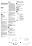
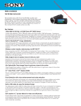
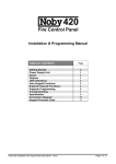
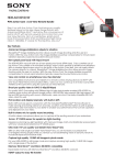
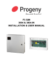
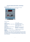
SIGNALING SYSTEMS
OPERATION MANUAL
SENTINEL PORTABLE
VIDEO CONTROLLER
MODEL: PVC
COPYRIGHT 2012 KARAS TECHNICAL SERVICES
ALL RIGHTS RESERVED
PUBLICATION NUMBER KTS-12012
FIRST EDITION
KARAS
KARAS TECHNICAL SERVICES
P.O. Box 695, Aptos, CA 95001 (831) 685-0816 Fax (831) 685-0817
web site: www.karastech.com
WARRANTY/DISCLAIMER
The products described in this manual are warranted to be free from defect in material and
workmanship for a period of two years from the date of shipment. Within the two year warranty period we shall replace or repair such products which are returned to us with shipping
charges prepaid and which are determined by us to be defective. This warranty does not
apply to any product which has been subjected to misuse, negligence or accident; or misapplied; or modified; or improperly installed.
The foregoing provisions are our sole obligation and exclude all other warranties or remedies, expressed or implied, including warranties of merchantability and fitness for a particular purpose, whether or not purposes or specifications are described herein.
We further disclaim any responsibility whatever to the customer or to any person for injury
to person, or damage to or loss of property or value during any use of our products. Under
no circumstances shall the company be liable for any incidental, consequential or special
damages or losses or expenses in connection with the use of, or inability of use of our product for any purpose whatsoever.
Warning: In installation and use of these products, comply with the National Electrical Code
or any other applicable local safety codes. During installation, turn off power and take all
other necessary precautions to prevent injury, property loss and equipment damage. Do not
apply power until all wiring is completed.
Product Changes: We reserve the right to discontinue a particular product or make technical design changes at any time without notice.
COPYRIGHT 2012 KARAS TECHNICAL SERVICES
ALL RIGHTS RESERVED
PUBLICATION NUMBER KTS-12012
FIRST EDITION
SENTINEL PORTABLE VIDEO CONTROLLER MANUAL
TABLE OF CONTENTS
DESCRIPTION . . . . . . . . . . . . . . . . . . . . . . . . . . . . . . . . . . . . . . . . . . . . . . . . . . . . . . . . . .1
OPERATION . . . . . . . . . . . . . . . . . . . . . . . . . . . . . . . . . . . . . . . . . . . . . . . . . . . . . . . . . . . .1
CONTROLS . . . . . . . . . . . . . . . . . . . . . . . . . . . . . . . . . . . . . . . . . . . . . . . . . . . . . . . . . . . .1
INDICATORS . . . . . . . . . . . . . . . . . . . . . . . . . . . . . . . . . . . . . . . . . . . . . . . . . . . . . . . . . . . .2
Video Controller Layout Diagram . . . . . . . . . . . . . . . . . . . . . . . . . . . . . . . . . . . . . . . . . .2
Set Up Connection Symbols . . . . . . . . . . . . . . . . . . . . . . . . . . . . . . . . . . . . . . . . . . . . . .2
SET UP . . . . . . . . . . . . . . . . . . . . . . . . . . . . . . . . . . . . . . . . . . . . . . . . . . . . . . . . . . . . . . . .3
Typical BNC Video Set Up Diagram . . . . . . . . . . . . . . . . . . . . . . . . . . . . . . . . . . . . . . . . .3
Operate Diagram . . . . . . . . . . . . . . . . . . . . . . . . . . . . . . . . . . . . . . . . . . . . . . . . . . . . . . . .4
Play Back Diagram . . . . . . . . . . . . . . . . . . . . . . . . . . . . . . . . . . . . . . . . . . . . . . . . . . . . . .4
DVR PROGRAMMING / SET UP . . . . . . . . . . . . . . . . . . . . . . . . . . . . . . . . . . . . . . . . . . . .5
WIRELESS RECEIVER . . . . . . . . . . . . . . . . . . . . . . . . . . . . . . . . . . . . . . . . . . . . . . . . . . .6
Programming Receiver Memory . . . . . . . . . . . . . . . . . . . . . . . . . . . . . . . . . . . . . . . . .6
Checking Memory . . . . . . . . . . . . . . . . . . . . . . . . . . . . . . . . . . . . . . . . . . . . . . . . . . . .6
System Testing . . . . . . . . . . . . . . . . . . . . . . . . . . . . . . . . . . . . . . . . . . . . . . . . . . . . . .6
Erasing Memory . . . . . . . . . . . . . . . . . . . . . . . . . . . . . . . . . . . . . . . . . . . . . . . . . . . . .6
WIRELESS SENSOR TRANSMITTERS . . . . . . . . . . . . . . . . . . . . . . . . . . . . . . . . . . . . . . .6
SPECIFICATIONS . . . . . . . . . . . . . . . . . . . . . . . . . . . . . . . . . . . . . . . . . . . . . . . . . . . . . . . .7
Video Controller . . . . . . . . . . . . . . . . . . . . . . . . . . . . . . . . . . . . . . . . . . . . . . . . . . . . . .7
Digital Video Recorder (DVR) . . . . . . . . . . . . . . . . . . . . . . . . . . . . . . . . . . . . . . . . . . .7
Video Camera . . . . . . . . . . . . . . . . . . . . . . . . . . . . . . . . . . . . . . . . . . . . . . . . . . . . . . .7
Video Monitor . . . . . . . . . . . . . . . . . . . . . . . . . . . . . . . . . . . . . . . . . . . . . . . . . . . . . . .7
Sensors . . . . . . . . . . . . . . . . . . . . . . . . . . . . . . . . . . . . . . . . . . . . . . . . . . . . . . . . . . . .7
Due to differences in customers requirements there may be discrepancies between your
Sentinel and this manual. If you have any questions regarding the operation of the
Sentinel Portable Radio Alarms, please contact Karas Technical Customer Service at
831 685-0816 or e-mail [email protected]
TYPICAL PORTABLE VIDEO RECORDER SYSTEM COMPONENTS
Monitor
Passive
Infrared Sensor
Video
Camera
Video
Controller
Illuminator
Cable Adaptors
Monitor
Wall Wart
Extension Cable
Illuminator
Portable
Video
Controller
Passive
Infrared
Sensor
Cable Adaptors
Antenna
Portable Video Controller shown in Carrying Case
DESCRIPTION:
The Portable Video Controller (PVC) is a small, compact, self-contained video recording
system controller in a water resistant case. It’s designed to be used in portable and remote
installations indoors or out. Ideally suit for stakeouts and surveillance applications. It is light
weight, energy efficient, easy to set up and install. It uses a SD memory storage device to
store the recorded information and can be read directly from the video recorder or from a
computer with an SD card slot. It can be operated with internal batteries and/or external
power sources. It can be used with a variety of video cameras and illuminators. With a built
in timer, it can be set to record for up to 60 minutes before turning its self off. It is activated
by either a wireless sensor such as a magnetic, seismic, passive infrared sensor or any of
the wireless Sentinel Portable Alarm sensors. It also has the ability to be activated from a
hard wired switch contact. The PVC maximizes its run time by turning off all unnecessary
circuits while in the receive mode.
OPERATION:
The video controller is used in conjuction with at a compatible video camera. Most modern
compact digital video cameras will work with the system. The selected wireless sensors need
to be programmed to the wireless receiver. Once they are programmed and triggered they
will active the PVC when ever it is turned on, with either internal or external power source.
The camera and optional illuminator power connections are connected to the timer
controlled 12 volt accessory power source. The camera video signal line is connected to the
Video input connection. An audio source may also be connected to the audio input
connection of the PVC to be recorded on th DVR.
When the PVC is turned on and the wireless receiver is activated by a wireless sensor
transmitter signal or the external trigger source it turns on the Digital Video Recorder, (DVR),
and the 12 volt accessory lead which activates the camera and other accessories. The built
in timer allows the user to set the DVR run time to be set from 1 to 60 minutes. When the
run time elapses, the PVC goes back into the receive mode and waits for another wireless
signal to activate the DVR.
When the controller is activated in the internal power source mode, the controller uses 8 AA
batteries to power the video controller and the camera and any other external device
requiring 12 volts. the internal batteries will operate the wireless receiver for 4 days on AA
alkaline batteries. The record time will be increased with NiMH batteries by almost double.
Increased record time will reduce the time the receiver will operate. Recording for 60
minutes with alkaline batteries will reduce the useable wireless receiver time by about half
of what it would be if it didn't record at all. In the external power mode, the internal circuitry
operates from a 10 to 15 DC power source such as a AC Adaptor or a 12 volt battery. The
length of run time is longer with a larger battery. A 7Ahr sealed lead acid battery, well
charged at room temperature, will typically operate the system for 12 to 15 days with
minimal recording time.
CONTROLS:
The Video controller has four control functions, two momentary switch buttons, one three
position slide switch and a run time control potentiometer.
The PROGRAM button is used to program the wireless sensors to the built-in wireless
receiver. The MANUAL START button is used to manually activate the controller during setup.
The slide switch(INT-OFF-EXT) is used to turn on the video controller from either of two
different sources of power. In the INT position, the video controller is getting its power from
the internal batteries. In the EXT position the video controller is getting its power from an
external source, such as a larger battery or AC Adaptor power source. The center position
is the OFF position.
The Run Time (RTIME) potentiometer determines the amount of time the DVR is powered
on. It can be set for 1 to 60 minutes or in setup, it can be set to run in seconds, up to 60
seconds, by removing the Secs jumper.
1
INDICATORS:
There are two LED indicators on the video control board. One is the SIGNAL indicator from
the wireless receiver. It also is used to indicate program status while programming wireless
sensors to the receiver. How these features are used are described in the wireless receiver
programming. The RUNNING LED indicates when the video controller is powering up the
DVR and accessories.
VIDEO CONTROLLER LAYOUT DIAGRAM
Antenna Connection
DVR
Internal
Digital Video Recorder
Audio/Video Input
Audio/Video Output
DVR Power Plug
Battery
Bank
Wireless Receiver
Program Button
Manual Start Button
VCR Running LED
Run Time Control
Watertite Connectors
Wireless Receiver LED
Camera & Illuminator
Accessory Power
Leads
Male BNC
Connector
External Power
Input
SET UP CONNECTION SYMBOLS:
CON 1
CON 2
M M
M F
F F
CON 3
CON 4
CON 5
CON 6
F
M
F F
M M
Male RCA to Male RCA
BNC T
Male RCA to Female BNC
POWER
Female
Female BNC to Female BNC
POWER
Male
Female RCA to Male BNC
POWER Y
Female RCA to Female RCA
RCA A/V CABLE
Male RCA to Male BNC
2
Alternate
Connectors
Audio &
Video
Inputs
SET UP:
Parameter Set Up. Before going into the field to set up the PVC system it is wise to check
and adjust DVR settings if necessary. Use the Playback Set Up with the AC Adapter for
power to check DVR set up parameters.
Use the External Power Source, Battery or AC Adaptor to power the monitor and camera
during set up while aligning the camera. If necessary, you may use the internal PVC batteries for set up but you will reduce the operate record time by draining some of the power
from the batteries. When camera set up is complete disconnect monitor and connect illuminator if used. Disconnect external battery from monitor/camera set up and reconnect to the
External Power Input if the AC Adapter is not used. You may use any 12 VDC power source
during camera set-up.
The DVR only records when it senses a video signal. It saves video to the SD card when
video stops with the accessory power turned off. If the DVR is shut off before or at the same
time as the camera the video data will not be recorded. Be sure to power Video Camera with
accessory power or the DVR will not record properly.
These diagrams do not use the Audio Input circuits. If Audio Recording is desired you will
need to connect an audio cable to the PVC Audio Input circuit and connect a microphone to
the audio cable. See Video Controller Diagram.
Although these diagrams show typical connections, you may wire up other devices with different types of connectors using the appropriate adaptors.
TYPICAL BNC VIDEO SET UP DIAGRAM
SD
Card
Audio
Not Used
Video In
A/V Input 2
A/V Input 1
Video Out
Power
Power
DVR
Monitor
12 Volt
Battery
CON 10
BNC T
Digital
Video Camera
CON 6
Accessory
Power
Illuminator
External Power
12
VOLT
DC
3
AC Adaptor
OPERATE DIAGRAM
SD
Card
Video In
Video Out
When using the video extension cable you will need to
use adaptor CON3 because the extension cable reverses
the sex of the BNC
Power
DVR
Video Extension Cable
Use CON 3 between PVC and Video Extension Cable
when using the Video Extension Cable as shown
BNC
M
BNC
M
Video
CON 3
Accessory
Power
Power
Digital
Video Camera
Illuminator
12 Volt
Battery
If Illuminator is near
camera, you may use
a power Y splitter to
power both the camera
and illuminator with
one power cable
RCA Audio Connectors are White
RCA Video Connectors are Yellow
or AC Adaptor
PLAY BACK DIAGRAM
Video
SD
Card
Video In
Video Out
Power
A/V Input 2
Audio (Not Used)
A/V Input 1
Power
DVR
Monitor
When using the DVR in Playback the
user has to press STOP on the DVR
then press PLAY. You may use the
search mode to look for and to review
recorded video. See DVR manual for
detailed Play Back instructions.
Accessory
Power
AC Adaptor
or Battery
External Power Input
4
DVR PROGRAMMING / SET UP:
The DVR comes set up from the factory for immediate use. These parameter value settings
are required for proper operation of the Sentinel Portable Video Controller. Should you need
to change them for different record rates, etc. see the DVR manual. DVR manual can be
downloaded for our website: www.karastech.com/Documents/MDVR-14manual.
DVR Power Switch needs to be in the DC Power Position
Refer to DVR manual for complete overview of all programming modes
Set R time to 60 minutes, to allow DVR to run continuously for 60 minutes while performing
set up procedures.
Factory Default
N/A
System Status
SD Card
Schedule Record
If used, complete Set-Up Procedure is required
SD
Full : Stop
Manual
: 704 x 480 10 FPS MQ
Motion
: OFF 12:00 - 23:59
352 x 240 30 FPS MQ
Do Not Change
Continue
: ON 00:00 - 23:59
704 x 480 30 FPS MQ
Do Not Change
Format > use F to reformat the SD card.
This erases all data on the SD card
Upgrade Boot loader > Do Not Use except to upgrade software
: OFF 12:00 - 23:59
352 x 240 30 FPS MQ
Do Not Change
: ON 00:00 - 23:59
704 x 480 30 FPS MQ
Do Not Change
Motion Record
: OFF
Do Not Change
Continue Record
: ON
Do Not Change
: 00:00 - 23:59
Do Not Change
Schedule
Manual Record
Video Size :
Frame Rate :
Quality
:
Audio
:
704 x 480
10 FPS
Medium
Off
Video Size :
Frame Rate :
Quality
:
Audio
:
704 x 480
10 FPS
Medium
ON
OK to Change
OK to Change
Set Motion Detect
NA Leave at system default (Do Not Use)
Set Date / Time
Set Date
Set Time
:
:
Search & Play
Set for Current Date and Time
Use for Playback from MDVR
5
WIRELESS RECEIVER:
The wireless receiver senses up to 32 transmitters. It is compatible with the standard
sensors used with the Sentinel Radio Alarm. You may use the same sensors to activate the
PVC system as well as Sentinel Radio Alarms, activating both systems at the same time.
Programming Receiver Memory:
Programming wireless sensors to be received by the wireless receiver is very simple.
1. the PVC has to be powered on, put power select switch in one of the two power modes,
internal or external. This turns on the receiver.
2. Now press and release the program button on the PVC circuit board.
3. The program signal indicator will light if there is room in the memory for another sensor
transmitter. (32 transmitter max.)
4. Send a signal from the wireless transmitter, the signal indicator light will flicker as the
signal is received.
5. Repeat steps 2 thru 4 for each additional transmitter. (Note: The receiver can memorize
each transmitter more than once. To prevent duplicate entries, program each transmitter
into the receiver only once.)
Checking Memory:
1. Press and hold for about two seconds until program signal indictor lights, then release.
2. Count the number of indicator blinks. This is the total number of transmitters
programmed.
System Testing:
1. Set the Rtime control on the PVC circuit board to one minute.
2. Activate each transmitter one at a time.
3. Look for the Running indicator to light. This indicates the signal was received. The PVC
will run for about one minute. To terminate the Run time, turn the power off momentarily
a repeat the process for each transmitter. You may remove the Secs jumper the operate
in seconds mode so the run time may be set to just a few seconds thus eliminating the
need to power off reset to restart the recorder.
Erasing Memory:
1. Press Program Button and continue hold it through the count of the number of
transmitters
2. Continue to hold the button after the count until the Signal indicator blinks one more time
(about five seconds after the count)
3. All transmitters programmed into memory will now be erased.
WIRELESS SENSOR TRANSMITTERS
Any of the Sentinel wireless sensors are able to activate the PVC. See the Sentinel Portable
Alarm Manual 2200 Series, for a more comprehensive list of Sensor Programming or
individual sensor data sheets for programming activation.
6
SPECIFICATIONS:
Video Controller:
Enclosure size: 8˝ x 5˝ x 3.75˝ Pelican waterproof case with weather tite fittings for .25”
diameter cables
Power source: Internal 8 AA batteries; External AC adapter or other battery
Interfaces: accessory power output, external power input, receiver antenna, DVR video and
audio inputs and outputs
Typical operating time from internal batteries, 30 minutes record time, 3 - 4 days; external
power recording time unlimited with AC adapter.
Operating temp.: -10ºC to 50ºC
Digital Video Recorder (DVR):
NTSC/PAL compatible video, low, medium, high resolutions, minimum of 75 minutes record
time per GByte.
Storage Media SD card, audio sampling 44.1 khz monoral (see DVR user manual for
complete specifications) www.karastech.com/Documents/MDVR-14manual
Video Camera: As shown in the photo of System Components prefacing page 1.
NTSC/PAL compatible, 1/3˝ Sony Super HAD CCD. Low Lux sensitivity .05, Operating
voltage 12V +/- 10% typical. Most video cameras will work with the PVC.
Power Consumption: 65 mA or less
Video Monitor:
See specific monitor specification sheet.
Sensors:
Compatible with all Sentinel Portable Radio Alarm sensors (Linear DX)
7
KARAS
KARAS TECHNICAL SERVICES
P.O. Box 695, Aptos, CA 95001 (831) 685-0816 Fax (831) 685-0817
web site: www.karastech.com