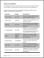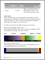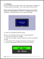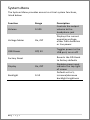
1
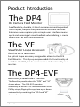
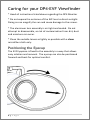
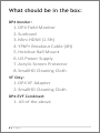
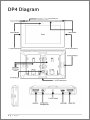
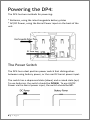
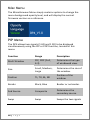
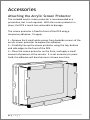
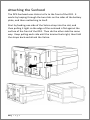
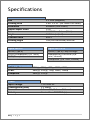
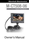
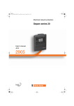
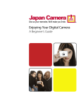
DP4 Field Monitor DP4-EVF Viewfinder User Manual Revision 1 0 Table of Contents Product Introduction................................................................................. 3 Caring for your DP4 Monitor..................................................................... 4 Caring for your DP4-EVF Viewfinder ......................................................... 5 Positioning the Eyecup .......................................................................... 5 What should be in the box: ....................................................................... 6 DP4 Monitor:......................................................................................... 6 VF Only: ................................................................................................. 6 DP4-EVF Combined: .............................................................................. 6 DP4 Diagram ............................................................................................. 7 Powering the DP4: .................................................................................... 8 The Power Switch.................................................................................. 8 Battery Plates: ....................................................................................... 9 Powering with AC/DC Power: ............................................................. 11 The DP4-EVF: ........................................................................................... 12 Overview ............................................................................................. 12 Attaching the VF to the DP4................................................................ 13 Detaching the VF from the DP4: ......................................................... 14 Using the DP4-EVF .............................................................................. 15 Using the DP4 .......................................................................................... 16 Operating the Menus .......................................................................... 16 The Preset Menu: ............................................................................ 17 DSLR Scale Presets .......................................................................... 18 Assigning Function Buttons ............................................................. 19 Image Menu ........................................................................................ 20 Advanced Menu .................................................................................. 21 1|Page False Color ....................................................................................... 22 1:1 Mapping .................................................................................... 23 Input Menu ......................................................................................... 24 Changing inputs: ............................................................................. 24 System Menu ...................................................................................... 25 Misc Menu .......................................................................................... 26 PIP Menu ............................................................................................. 26 Accessories .............................................................................................. 27 Attaching the Acrylic Screen Protector ............................................... 27 Attaching the Sunhood ....................................................................... 28 Updating Firmware ................................................................................. 29 Specifications .......................................................................................... 30 Warranty ................................................................................................. 31 Thank You! .............................................................................................. 32 2|Page Product Introduction The DP4 On Camera Field Monitor An affordable, durable, 4.3-inch on-camera monitor packed full of inputs, outputs and professional software features. Extensive menu options plus a simple user interface means quick and meaningful visual feedback when dialing in crucial details such as focus and exposure. The VF Viewfinder Loupe Accessory for the DP4 Monitor An optical loupe accessory designed to attach to the DP4 Field Monitor. This flip-up eyepiece adds the functionality of an EVF to the DP4, but does not remove its functionality as a monitor. The DP4-EVF Monitor/Viewfinder Combo The Resulting combination the “DP4” and “VF” shown above. The DP4-EVF operates seamlessly as either a 4.3-inch monitor or as an EVF by simply flipping the eyepiece up or down and results by combining the “DP4 and “VF” shown above. 3|Page Caring for your DP4 Monitor * The DP4’s DC input is CENTER PIN POSITIVE. Always check polarity of any custom cable implementations. SmallHD is not liable for any power related damage to your monitor due to incorrect polarity. * The DP4’s max input voltage is 18vDC. Over powering can result in damage to your DP4. SmallHD is not liable for any damage due to overpowering the unit. * Not all power sources are created equal. Using off-brand (nonCanon) LP-E6 batteries can result in undesired performance and longevity issues. * Do not attempt to disassemble the DP4. Doing so voids warranty. * SmallHD support for further instructions. Water damage is not covered by warranty, but taking the right precautions when a water event occurs can sometimes preserve unit functionality. * Clean the screen with a high quality microfiber cloth only. Never spray the screen directly with any sort of cleaning fluid. * Always ask us if you have any questions about general operation. Contact SmallHD at www.smallhd.com/support *Much more information about the DP4 and other SmallHD products can be found online on our website and in video form at www.smallhd.com 4|Page Caring for your DP4-EVF Viewfinder * Heed all instructions listed above regarding the DP4 Monitor * Do not expose the entrance of the EVF lens to direct sunlight. Doing so can magnify the sun and cause damage to the screen. * The aluminum lens assembly is air tight and sealed. Do not attempt to disassemble, as risk of contamination from dirt, dust and moisture can occur. * Clean the outside lenses as lightly as possible with a clean microfiber cloth only. Positioning the Eyecup The EVF Eyepiece is fixed to the assembly in a way that allows easy rotation and removal. The eyecup can also be positioned forward and back for optimal comfort. 5|Page What should be in the box: DP4 Monitor: 1. DP4 Field Monitor 2. Sunhood 3. Mini-HDMI (1.5ft) 4. YPbPr Breakout Cable (4ft) 5. Hotshoe Ball Mount 6. US Power Supply 7. Acrylic Screen Protector 8. SmallHD Cleaning Cloth VF Only: 1. DP4 VF Adapter 2. SmallHD Cleaning Cloth DP4-EVF Combined: 1. All of the above 6|Page DP4 Diagram / Composite Out 7|Page Powering the DP4: The DP4 has two methods for powering: * Batteries, using the interchangeable battery plates * AC/DC Power, using the Barrel Power input on the back of the unit. The Power Switch The DP4 has a dual position power switch that distinguishes between using battery power, or the rear DC barrel power input. The switch has a depressed state (down) and a raised state (up). To use batteries, the switch should be DOWN. To use AC/DC Power via the barrel power input, the switch should be UP. 8|Page Battery Plates: The DP4 comes standard with a dual LPE6 battery plate that is removable/replaceable with other types of plates that will be released. * Batteries can be used either in a single or double arrangement * Power switch should be depressed to activate battery power * Battery voltage can be read onscreen in the DP4 Menu System by activating “Voltage Meter” in the “System” Menu. Removing Battery Plates: The battery plates are not attached by screws, they just need the correct amount of force applied in the correct places to detach from the DP4 body. Some popping noises may occurr during the battery plate removal process—this is normal and expected. Method 1: The recommended method is to insert a small flat-head screwdriver into the corner slot where the battery plate meets the metal body, then pull towards the rear of the DP4, lifting the corner of the plastic plate away from the metal DP4 housing. 9|Page Method 2: Thread the ¼ 20 thread of the included ball mount into one of the two side ¼ 20 mounts a few times, then pull towards the rear using the body of the ball mount as leverage. Replacing Battery Plates: Replacing battery plates is as simple as aligning the plate to the back of the DP4 and pressing in on the 4 corners. You should hear 4 audible “click” noises to confirm that it is completely attached. 10 | P a g e Powering with AC/DC Power: The DP4 has a barrel power input for powering from a wall using the included power supply, or from other sources such as Anton Bauer batteries. The specifications of this plug are below: **ALWAYS CHECK POLARITY BEFORE USING ANY POWER SOURCE THAT ISN’T THE INCLUDED POWER SUPPLY. 11 | P a g e The DP4-EVF: The DP4-EVF as a unit combines the DP4 Monitor (aka "DP4") and the DP4 Viewfinder Loupe Accessory (aka "VF"), which simply fixes to the front of the DP4 without the need for screws or adhesive. Overview 12 | P a g e Attaching the VF to the DP4 * Hold the VF with one hand and with the other, put one side of the DP4 in place, and then firmly press down on the other side to snap the VF in place. 13 | P a g e Detaching the VF from the DP4: Using your thumb, pull one of the side tabs of the VF back, then release the DP4 from that side—the other side will come out on its own once the first side is free. 14 | P a g e Using the DP4-EVF * The DP4-EVF incorporates magnets and a hinge to operate in two modes, closed and open. This makes it easy to quickly go from shooting mode to review mode, or something else and not have to fiddle with latches or screws. * To adjust the eyepiece, simply rotate it to the most comfortable position. * The front of the lens assembly has standard 46mm threads for the use of diopters and UV filters. This will add thickness to the front and in some cases may protrude too far for comfort. This can be resolved by pulling the rubber eyecup back until it is flush around the very first element. 15 | P a g e Using the DP4 Operating the Menus 1 – Navigation Scroll Wheel * Click to activate Main Menu * Click to select items in menu * Scroll right and left to adjust values *(From no menu) Scroll any direction to access Preset menu 2 – Back button/Preset A * Press to reverse out of the menu * Activate/deactivate Preset 3 – Preset B Button * Activate/deactivate Preset Activating the menu and adjusting a function: 1 – Click the scroll wheel one time 2 – Roll the scroll wheel left or right to the proper sub menu 3 – Click the wheel to select the sub menu 4 – Roll the wheel to select the desired menu item 5 – Click the wheel to select the desired menu item 6 – Roll the wheel left or right to adjust the value 7 – Press the back button to exit out of the menu system 16 | P a g e *NOTE: SmallHD monitor software is constantly under development, which means there is a chance this manual might not always be accurate. Always refer to online documentation and videos for the most up-to-date information on DP4 software. *Many of the menu functions are described in video format on the video section of the SmallHD website. The Preset Menu: The Preset menu is a list of selectable presets that can perform a variety of advanced functions. Named presets are preprogrammed to perform specific functions; therefore some of their parameters cannot be modified by the user. Generic presets (with the name "Preset" followed by a number) will store menu adjustments made to the DP4 in real time. The selected preset can be seen in the bottom right corner of the Main menu. The "Viewfinder" preset is selected by default, providing more appropriate backlight brightness when viewing DP4's screen through the eyepiece of the Viewfinder accessory. Accessing the Preset Menu: While not in any menus: 1 – Roll the scroll wheel to the left to display the menu 2 – Roll the wheel to the desired preset 3 – Click the wheel to select the preset 4 – Press the back button (button A) to exit the preset menu NOTE: The DP4 (version 1.0 of firmware) comes with the default brightness set to 5. This is because the DP4 is very bright, and using the DP4 in EVF mode with the brightness at 10 can cause discomfort. When not using the EVF, the DP4’s brightness can be increased to 10, allowing for better outdoor usability. 17 | P a g e DSLR Scale Presets The DSLR Scale presets are factory defined presets that enable the input signal from a variety of DSLR cameras to fill the screen of the DP4. Most monitors are unable to achieve this function. Special logic is in play when these presets are activated that keeps the image in full-screen mode even though the video signal may be changing aspect ratios behind the scenes (as in the case of the Canon 5D Mark 2, 60D, T2i, and T3i). As a result, the "Scale" and "CustomScale" menu functions are locked while using these presets. NOTE: Use preset "C DSLR REC" for Canon DSLR cameras during LiveView/Record mode. Use preset "N DSLR REC" for Nikon DSLR cameras during LiveView/Record mode. Use preset "PLAYBACK" when reviewing footage already recorded onto the Canon/Nikon DSLR. 18 | P a g e Assigning Function Buttons The DP4 has two buttons that can be assigned to custom functions for a convenient one press on/off of your favorite features. While not in any menus: 1 – Press and hold either of the two buttons (A or B) for 3 seconds and release 2 – Scroll with the scroll wheel to the desired function and click the scroll wheel to select it 3 – Press the Back button to exit the menu 19 | P a g e Image Menu The image menu controls Brightness, Contrast, Hue, Saturation, Sharpness and Gamma. Below is a description of each. Function Range Description Brightness 0-100 Controls the maximum black point of the signal. Contrast 0-100 Controls the maximum white point of the signal. Hue 0-100 Also known as Tint or Phase. Saturation 0-100 Also known as Chroma. Sharpness 0-100 Amount of edge enhancement is applied. RGB Control 0-100 Adjusts RGB Gain and Offset for all 3 color channels. Gamma 2.2 Standard Gamma adjustment. 20 | P a g e Advanced Menu The Advanced menu provides access to the many software tools of the DP4 to, among other things, aid in focus and exposure. Some of the functions are explained in greater detail in later pages, marked by the asterisk (*). Function Range Description Focus Assist On, Off Darkens image and outlines area in focus in white. False Color* HML, HL Overlays varying IRE levels in specific colors. Peaking On, Off Over-sharpens the image to give a frosted look to areas in focus. 1:1 Mapping* On, Off Maps the native signal data to the screen of the DP4 – one native pixel to one DP4 screen pixel, no scaling. Scale 16:9, 4:3, 2.35:1, 1.85:1, AUTO Defines the initial scaling parameters for the DP4. 16:9, 4:3, etc. CustomScale 0-1000(x4) Blue Only On, Off Monochrome 21 | P a g e On, Off Stretch, shrink and move the image on screen pixel-bypixel. Turns the Red and Green color channels off. Used for calibrating to color bars. Removes all color and leaves only the Luminance data of the signal. Image Flip H, V, HV Flip the image horizontally, vertically, or both. Freeze On, Off When activated will freeze the image on-screen. Turn off to resume normal video. False Color False color evaluates the incoming IRE levels (exposure) of the signal and then changes the colors of the pixels to represent what those IRE levels are. This is a quick way to gauge the exposure levels within an image in a very clear way. The DP4 currently has two different types of False Color. False Color HML (High / Mid / Low) Meaning High, Medium, Low, has colors for over-exposed, underexposed and mid-range. The scale is below: BLUE PURPLE ORANGE GREEN YELLOW False Color HL (High / Low) Meaning High, Low, has colors for over and underexposed. The remaining middle will be monochrome. 22 | P a g e 1:1 Mapping When activated, each native pixel of the input signal is mapped to a native pixel on the display. This is also called “Pixel to Pixel”. When viewing HD signals (720p and up), only a portion of the image will be displayed on the DP4 as 1:1 Mapping essentially performs a "zooming" effect on the native HD image. To move the viewable window around: When 1:1 is activated and no menu is being displayed: 1 – Roll the scroll wheel to the left 2 – Now roll the wheel in either direction to move the window around 3 – Press button B to change the direction of movement 4 – Press the back button (Button A) to exit this dialog 23 | P a g e Input Menu The DP4 has 3 inputs to choose from: 1 – HDMI 2 – YPbPr (SD/HD Component) 3 – Composite (SD Only) Changing inputs: 1 – Navigate to the “Input” sub menu with the scroll wheel 2 – Scroll to the desired input 3 – Click the scroll wheel once 24 | P a g e System Menu The System Menu provides access to critical system functions, listed below: Function Range Volume 0-100 Description Controls the output volume to the headphone jack Voltage Meter On, Off Displays the current operating voltage, either from batteries or line power. USB Power Off, 5V Toggles power to the USB port, on or off. Reverts the DP4 back to factory defaults Factory Reset Display On, Off Backlight 0-10 25 | P a g e Disables green input indicator on top right of screen Default set to 5, increase/decrease backlight brightness Misc Menu The Miscellaneous Menu simply contains options to change the menu background opacity level, and will display the current firmware version as a reference. PIP Menu The DP4 allows two signals (1 HD and 1 SD) to be displayed simultaneously using the PIP or POP function, located in this menu. Function Range PIP, POP (Full, 4:3) Description Determines the type of windowed view. Size Small, Medium, Large Determines the size of the window. Position TL, TR, BL, BR Position of the window. Border Black, Blue Border or no border. Sub Source Composite Determines the secondary source. Swap Swap Swaps the two signals Multi Window 26 | P a g e Accessories Attaching the Acrylic Screen Protector The included acrylic screen protector is recommended as a precaution, but is not required. With the screen protector in place, the DP4 is much less vulnerable to damage. The screen protector is fixed to front of the DP4 using a temporary adhesive. To apply: 1 – Remove the 4 small white pieces from backside corners of the acrylic screen protector to expose the adhesive. 2 – Carefully line up the screen protector using the top, bottom and side edges to the front of the DP4. 3 – Place the screen protector on the front, and apply a small amount of pressure at the corners. It is not necessary to press hard; the adhesive will bond more on its own over time. 27 | P a g e Attaching the Sunhood The DP4 Sunhood uses Velcro to fix to the front of the DP4. It works by looping through the two slots on the sides of the battery plate, and then reattaching to itself. Start by feeding one side of the Velcro strap into the slot, and then pulling it tight so the edge of the sunhood is flat against the surface of the front of the DP4. Then do the other side the same way. Keep pulling each side until the tension feels right, then fold the straps back and attach the Velcro. 28 | P a g e Updating Firmware The DP4 has the ability to upgrade its firmware based on new software developments. This is a unique ability of SmallHD monitors, and is very easy to do. To upgrade: 1 – Format your USB thumb drive to FAT file system 2 – Download the .BIN file from www.smallhd.com/support 3 – Copy the .BIN file to your thumb drive 4 – Insert the thumb drive into the included adapter cable and plug the mini-usb cable into the mini-usb port of the DP4 5 – Hold down the scroll wheel and then turn the DP4 on. 6 – On screen instructions will inform when the process is complete. 29 | P a g e Specifications LCD Size Viewing Area Resolution Native Aspect Ratio Color Brightness Contrast Ratio Viewing Angle 4.3 inch (diagonal) 3.69” x 2.21” (93.7mm x 56.2mm) 800x480 (RGB Pixels) 15:9 16.7 Million Colors (8 bit) 350 Nits (cd/m2) 800:1 160/160 Horizontal/Vertical Signal INPUTS HDMI (Type A) YPbPr/Component (1/8” Mini) CVBS/Composite Signal Compatibility HDMI In/Out YPbPr Composite Power Input Voltage Consumption (MAX) Power Connector Polarity 30 | P a g e Signal OUTPUTS HDMI (Type A) Loop through Headphone/ Line Level (1/8” mini, shared) Composite (1/8” mini, shared) 480i/p, 576i/p, 720p, 1080i, 1080p 480i/p, 576i/p, 720p, 1080i, 1080p 480i/p, 576i/p 7-18 Volts DC 5.5 Watts 5.5mm OD / 2.1mm ID Barrel Center Pin – POSITIVE (+) Warranty The DP4 comes with a one year limited hardware warranty. The limited hardware warranty covers defects in materials and workmanship of our products. Warranty specifics: Warranty period begins on date of shipment Warranty is non-transferable; products not purchased directly from SmallHD or SmallHD approved affiliates and distributors do not qualify for warranty coverage. The customer shall be responsible for paying shipping charges required to return products to SmallHD for warranty repair. SmallHD shall pay for shipping of repaired products to the customer. What is not covered by our warranty: Problems resulting from accidents, abuse, or misuse Problems resulting from electrical power source issues 3rd-party servicing not authorized by SmallHD Failure to follow product instructions Water damage Scratches to the body or panel that occur as part of normal use For Dead Pixel Policy and other Warranty information, visit our website at www.smallhd.com/support 31 | P a g e Thank You! Most importantly, we value your patronage. If you have any questions about general or extreme use, or want access to the latest documentation, videos, firmware and general information, please visit www.smallhd.com. 32 | P a g e 33 | P a g e