1
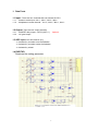
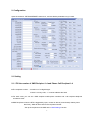
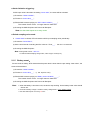
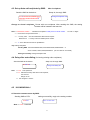
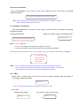
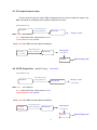
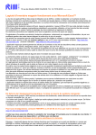
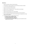
GSM SMS Modem
MODEL: SKY RTU-1
User Manual
V1.02
1
CONTENTS
1. Data Ports ...................................................................................................................................................3
1.1 Input ..............................................................................................................................................................3
1.2 Output ...........................................................................................................................................................3
1.3 ADC input ....................................................................................................................................................3
1.4 RXD/TXD ......................................................................................................................................................3
2. Configuration ................................................................................................................................................5
2.1 Setting ...........................................................................................................................................................5
2.1.1 Fill the number of SMS Recipient 1-4 and Phone Call Recipient 1-4 ...............................................5
2.1.2 Input ............................................................................................................................................................6
2.1.3 Output .........................................................................................................................................................8
2.1.4 ADC Input Detecting.................................................................................................................................8
2.1.5 Battery event ..........................................................................................................................................9
2.1.6 RTU Initok ................................................................................................................................................10
2.1.7 Power down .............................................................................................................................................10
2.1.8 Password .................................................................................................................................................10
3. RTU configure ............................................................................................................................................. 11
4. Immutable SMS Format ............................................................................................................................12
4.1. Modify PASSWORD .................................................................................................................................12
4.2. Set up SMS recipients by SMS ..............................................................................................................12
4.3. Set up Auto-call recipients by SMS ........................................................................................................13
4.4. Delay after auto-dialing ............................................................................................................................13
4.5 IN1/IN2/IN3/IN4+/- ..................................................................................................................................13
4.6 ADC...........................................................................................................................................................14
4.7. OC output channel setup .........................................................................................................................15
4.8 OPTO Output Port ....................................................................................................................................15
2
1. Data Ports
1.1 Input : There are four channels that can activate the RTU
1.1.1
1.1.2
Common active input: IN1+/-; IN2+/-; IN3+/-; IN4+/-.
Multiplexed counter channel: IN1+/-; IN2+/-; IN3+/-; IN4+/-.
1.2 Output: There are two output channels
1.2.1
1.2.2
MOSFET relay output---OPTO (OUT+/-)
OC gate output.
Optional
1.3 ADC input: One AD channel. (5V)
>> Activated by a number over the limitation
>> Activated by a number under the limitation.
>> Activated by a timer.
1.4 RXD/TXD
Download the setting parameter.
3
Electrical Characteristics @25℃
Parameter
Min.
Power Voltage
Max.
7.5V
Power Current
IN1-4+/- Optocoupler (Iso)
Input Drive Voltage
IN1-4+/- Optocoupler (Iso)
Input Drive Curent
Typ.
25V
12V
500mA
50mA
2.5V
48V
0.5mA
45mA (continuous)
100V
IN1-4+/Reverse Patient Voltage
Output Current Drive ability note
<100mA
Optocoupler (Iso)
Output Patient Voltage
60V
note
Frequency of counting
10KHz
Range of ADC Voltage
50V
ADC Digit
8BIT
ADC Precision
ADC Input Impedance
0-5V
+/- 2%
50Kohm
OC Drive Current
<500mA (continuous)
4
2. Configuration
Open the software: “PRTUMODEMSET1123en.exe”, and set relative parameters as you need.
2.1 Setting
2.1.1 Fill the number of SMS Recipient 1-4 and Phone Call Recipient 1-4
◘ The recipients number: A maximum of 16 digits length.
If there is country code, “+” must be added at the head.
◘ For each event, you can set 4 SMS recipient mobile-phone numbers and 4 call recipient telephone
numbers at most.
◘ SMS Recipients: when the RTU is triggered by input, counter or alert of power down(or battery lower
than limit ), SMS will auto-send to the recipients number.
Set up the recipients of the SMS at the “SMS Settings” section.
5
◘ Phone call Recipient: when the RTU is triggered by input , counter or alert of power down(or battery
lower than limit ), RTU will auto-call to the recipients number and hung up.
Set up the recipients of the call number at the “Telephone Settings” section.
2.1.2 Input : There are four factors that can activate the RTU,
◘ The four Input channels: IN1+/-; IN2+/-; IN3+/-; IN4+/-;
Both the rising edge and the failing edge can activate the RTU.
1) Choosing the triggering channel: IN1+/-; IN2+/-; IN3+/-; IN4+/2) Choosing the triggering mode: on “IN1-4”
> Rising edge
> failing edge
> rising and failing edge
3) Edit the SMS content replying on “SMS Content: IN1-4 Rising/Falling Edge_____”:
The content of each event,no longer than 32 characters.
4) Choosing the SMS Recipient and Phone call Recipient
For example: if SMS are to be sent to Rep1 and Rep3 through channel 1, TEL1 and TEL3 are to
be clicked on “IN1 SMS Recipients”.
◘
IN1-4+/- : When choose “Counter Function”, IN1+/-;
IN2+/-;
IN3+/-;
IN4+/- are used as
multiplexed counter channel, the falling edge and the rising edge of IN1+/-; IN2+/-; IN3+/-;
IN4+/- will be invalid. The channel can be activated by a pre-setting value. If there is overflow,
it will loop.
Switch back battery on to save the value having counted.
Period send: When time up the RTU will report the value via SMS to recipients, after reporting the
counter will not reset to zero. When counting to 655360, auto reset to zero.
1) choose “Counter Function” >> ’ Period send’ , the IN1+/-; IN2+/-; IN3+/-; IN4+/- will count
input trigger (or pulse), send the data periodically if clicked.
2) the period is set on ‘timer__’ ; min is 1min ; max is 65535min
3)Choosing the SMS Recipient and Phone call Recipient of the channel
For example, you select period send of IN1, IN2, IN3, IN4 Event and set the time 60mins, then after
60mins, modem will send SMS as below format:
C1=nnnnnn; C2=nnnnnn; C3=nnnnnn; C4=nnnnnn; to recipients.
The C1=/C2=/C3=/C4= should be set and editable at “IN1 counter”, “IN2 counter”, “IN3
counter” and “IN4 counter”.
6
For example:
A. You input C1= at IN1 counter, C2= at IN2 counter, C3= at IN3 counter, C4= at IN4 counter, and select
period send function on IN1,IN2,IN3,IN4 event,
Then modem will send SMS like C1=nnnnnn; C2=nnnnnn; C3=nnnnnn; C4=nnnnnn; to recipients.
B. You input CAFEO at IN1 counter, blank at IN3 counter, and select period send function on IN1, IN3
event,
Then modem will send SMS like CAFEOnnnnnn; nnnnnn; to recipients.
(Note: The recipients number is decided by IN3 recipients only, it means the period send number is
according to IN3 setting)
Value send:
After the counter counts to the preset value, RTU will be activated to send SMS to
recipients and then the counter will reset to zero automatically.
1) choose ‘Counter Function’>> ‘Enable preset’, If choose, the IN1+/-; IN2+/-; IN3+/-; IN4+/will count trigger (or pulse), when counts to the preset value, RTU will be activated to send SMS
to recipients()
2) the value is set on ‘Preset Num____’ range is 1~ 500000.
3) Edit the SMS content replying on “IN1 Counter__
IN2 Counter__
IN3 Counter__
IN4 Counter__”
The content of each event,no longer than 32 characters.
4) Choosing the SMS Recipient and Phone call Recipient of the channel.
For example:
A. You input C1= at IN1 counter, C2= at IN2 counter, C3= at IN3 counter, C4= at IN4 counter, and select
Enable Preset function on IN1,IN2,IN3,IN4 event,
Then modem will send SMS like C1=nnnnnn;
C2=nnnnnn;
C3=nnnnnn;
C4=nnnnnn;
to relative recipients.
(Note: this is four messages.)
B. You input CAFEO at IN1 counter, select Enable Preset function on IN1 event,
Then modem will send SMS like CAFEOnnnnnn; to relative recipients.
7
Sampling Interval:
range 0-255; unit: ms
When the interval is “1”, sampling period is 1ms, sampling frequent is 1000Hz, input inplus less than
500Hz
When the interval is “100”, sampling period is 100ms, sampling frequent is 10Hz, input inplus less than
5Hz
2.1.3 Output:
There are two output channels: MOSFET Relay output (OPTO)
OC gate Output
Output mode: pulse
Outputs trigger by SMS commands: Send
Stop sending
Send designated numbers of pulses
The width and the period of the pulse can also be set.
OPTO Pulse Width___: the width for OPTO output pulse, unit is 10ms
OPTO Pulse Period___: the period for OPTO output pulse, unit is 10ms
OC Gate Pulse Width__: the width for OC output pulse, unit is 10ms
OC Gate Pulse Period__: the period for OC output pulse, unit is 10ms
2.1.4 ADC Input Detecting
The max sampling data of ADC is 255, it corresponds input is 5V
There are three events can trigger ADC function:
Note: if active the “ADC Event”, but without ADC input, the value of voltage of ADC is 0v
◘ Over limitation:
If ADC input value is higher than the setting “higher value”, the event will be activated.
1) Choose the ‘Over limitation’ ;
2) Fill value in “Higher value___”.
3) Edit the SMS content replying on “ADC over Limitation______”:
The content of each event, no longer than 32 characters.
4) Choosing the SMS Recipient and Phone call Recipient
Note: the alert SMS reports once every 5mins
8
◘ Under limitation triggering:
If ADC input value is less than the setting “lower value”, the event will be activated.
1) Choose the ‘Under limitation’;
2) Fill value in “lower value___”.
3) Edit the SMS content replying on “ADC Under Limitation______”:
The content of each event,no longer than 32 characters.
4) Choosing the SMS Recipient and Phone call Recipient
Note: the alert SMS reports once every 5mins
◘ Period sampling value send:
If ‘Period Send’ is clicked, RTU will send the ADC input sampling value periodically.
1) Choose the ‘Period Send’;
2) Set the time interval of sending the ADC value on ‘Timer___’. the min is 10 seconds
3) Choosing the SMS Recipient
Note: sending SMS content:ADC=xxx
xxx indicate ADC Sampling voltage value, value range is 0-255 (0-5V)
2.1.5
Battery event:
if there is built in battery, RTU detects that the power level is lower than the pre-setting “lower value”, the
event will be activated.
1) Choose the ‘Under limitation’ ;
2) Fill value in “lower value___”. (> 153: equal to 3.6v)
3) Edit the SMS content replying on “Battery under Limitation______”:
The content of each event,no longer than 32 characters.
4) Choosing the SMS Recipient and Phone call Recipient
Note: >> when the battery is low about 3.4V, the device stop working. So the battery lower value should
above 153.
>> Formula of Battery voltage: LowValue= battery voltage/6*255 = 42.5 * battery voltage.
>> the alert SMS reports once every 10 mins
9
2.1.6 RTU Initok
A. System initialization complete (by power supply or battery), send the SMS to recipient 1
B. Report when power supply on, while supported by back-up battery, send the SMS to recipient 1
Edit the SMS content replying on ‘RTU Initok ___’.
Note: the initok SMS only report to “recipient 1”
2.1.7 Power down:
when the power supply disconnected or power off, the RTU will send SMS to recipient 1
Edit the SMS content replying on ‘RTU Power down ___’.
Note: the power down SMS only report to “recipient 1”
2.1.8 Password:
Four digits,ASC code
After Setting , press ”save” to save the configure value.
Appendix:
‘Upload’ : press the key to read out the configure out from the RTU modem.
‘Read’ : open the configured file.
10
3. RTU configure
3.1 connecting the data cable to the modem and computer
POW GND
IN1
+
IN1
-
IN2
+
IN2
-
IN3
+
IN3
-
IN4
+
IN4
-
OUT OUT ADC/ OC/
+
RXD TXD
blue
black
+ or battery
RS232
white
to computer
3.2 Run the software “RTU Modem Setting”. Select the files to download(by “Read” to open the saved
file).
3.3 Click “download”. the” Serial Port Status ” turns to green
“Communication” begins to flash
3.4 Power on the RTU modem (by power or battery). When the connection well for download, the
“Communication” turns to green;
3.5 In 1~2 seconds, downloaded successfully, press” ok ”
All setup is OK, RTU will
initialize to detect all the conditions If
the conditions are met, RTU
will check whether it is enabled. If it is
enabled, RTU will look for the SMS recipients and send the pre-set SMS if the recipients do exist.
11
4. Immutable SMS Format
4.1. Modify PASSWORD
Send the SMS to the device:
Setup successful, it replies :
xxxxEnnnn#
Change Password Ok!
Note: >>xxxx refers old Password; nnnn is new Password. It is constituted by 4 ASCII codes.
>> Factory default:1234.
>> The password is case sensitive
4.2. Set up SMS recipients by SMS :
Max 4 recipients
Send the SMS to the device:
Setup ok, the reply SMS:
xxxxRaaaaaaaaaaa;bbbbbbbbb
Change Recipients Ok!
bbb;cccccccccccc;ddddddddd#
Change or Cancel recipients: Re-set with new recipients. After sending the SMS, the setting contents will
be instead to the last time
Note: >> xxxx:
the Password
>> aaaaaa, bbbbbbbbbbb……indicates the recipients mobile phone number.
1-16 ASC or digits.
>> the numbers are spaced between ‘ ; ’
>> “+country code” must be added when SMS format requires
SMS Format: + Country Code and mobile phone number.
>> “R” in the SMS format must be capitalization
Exp: setting Recipients:
Sending SMS: 1234R+8613666504825;+23413666502528;13908333355# or
xxxxR+123456;+45679;45646;45646#123 (the num after ‘#’ are invalid)
Setting successfully: Change Recipients Ok!
12
4.3. Set up Auto-call recipients by SMS :
Max 4 recipients
Send the SMS to the device:
Setup ok, the reply SMS:
xxxxTeeeeeeeeee;fffffffffffff;gggg
Change Recipients Ok!
ggggggg;hhhhhhhhhhhhhhh#
Change or Cancel recipients:Re-set with new recipients. After sending the SMS, the setting
contents will be instead to the last time
Note: >> eeeeeeeee, hhhhhh……indicates the recipients mobile phone or PSTN number. 1-16 ASC or digits.
>>
the numbers are spaced between ‘ ; ’
>>
“+country code” must be added when SMS format requires
SMS Format: + Country Code and mobile phone number.
>>
“T” in the SMS format must be capitalization
Exp: setting Recipients:
Sending SMS: 1234T+8613666504825;+23413666502528;13908333355# or
xxxxT+123456;+45679;45646;45646#123 (the num after ‘#’ are invalid)
Setting successfully: Change Recipients Ok!
4.4. Delay after auto-dialing (for leaving missing call to recipients)
Send the SMS to the device:
Setup ok, the reply SMS:
xxxxDTnn#
Note:
Change Dial Delay Ok!
>> xxxx is the password
>> nn indicates the relay after device call recipients;
Unit: second
Range: 05-40
>>
4.5
the configure is 10secs
IN1/IN2/IN3/IN4+/-
A. Reset the counter to zero by SMS:
Sending SMS to RTU:
xxxxCC
setting successfully, reply to the setting number:
Clear counter Ok!
Note: >> xxxx : Password
13
B. Period send method:
when IN1/IN2/IN3/IN4+/- are used as ‘Period send’ channel, the RTU will send to pre-setting
recipients the SMS:
C1=nnnnnn;C2=nnnnnn;C3=nnnnnn;C4=nnnnnn
Note: nnnnnn: indicates the counting value at that time, the range of counting is 1-655359,
when counting to 655360, auto clear to zero.
C. Fixed Value send method
when IN1/IN2/IN3/IN4+/- are used as value trigger channel, the RTU will send to pre-setting
recipients the SMS:
Sending Setting SMS:
setting successfully, reply to the setting number:
Set Precounter Ok!
xxxxSCnnnnnn#nnnn#nnnnn#nnnnn#
Note: >> xxxx : Password
>> nnnnnn: Pre-setting count amount; the range is 1-500000
>> Count amount will not be lost after power off, save by working of battery.
When pulses from the sensor reach the pre-setting value, the GSM RTU send SMS to recipients:
-------- C1=nnnnnn OR
C2=nnnnnn OR
C3=nnnnnn OR
C4=nnnnnn
Note: >>nnnnnn: indicates the counting value at that time, the range of counting is 1-655359
>> the counter will reset to zero automatically after reporting SMS , and then counts repeatly
>> The value have counted will not be lost if power off (supported by battery)
4.6
ADC:
Trigger ADC to ‘Period Send’, the RTU will send the voltage sampling value periodically to
pre-setting recipients the SMS:
ADC=xxx
Note: xxx: indicates the voltage value at that perod, the range of is 0-255
Query ADC
Sending Setting SMS:
successfully, reply to query phone:
C=xxx
xxxxQA
14
4.7. OC output channel setup
There is and OC gate for output. SMS commands can be used to enable the output. And
SMS commands can designate the numbers of impulse to be sent.
Send SMS to unit:
successifully reply to
setting mobil-phone
xxxxOCPaa
Set OC Ok!
Sending aa pulse
Note: xxxx : the Password
aa: output pulse times; setting range is 01-99
pulse width/period: are optional.
when aa=00 the SMS unit send pulse constantly
successifully reply to
xxxxOCP00
or
setting mobil-phone
Sending pulse
Set Opto Ok!
OUT+/OUT-
xxxxOCE
xxxxOCR
Stop sending pulse
4.8 OPTO Output Port (MOSFET relay): OUT+/OUTSend SMS to unit:
successifully reply to
setting mobil-phone
xxxxTOPaa
Sending aa pulse
Set Opto Ok!
OUT+/OUT-
Note: xxxx : the Password
aa: output pulse times; setting range is 01-99
pulse width/period: are optional.
when aa=00 the SMS unit send pulse constantly
successifully reply to
xxxxTOP00
setting mobil-phone
Set Opto Ok!
Sending pulse
OUT+/OUT-
or xxxxTOE
xxxxTOR
15
Stop sending pulse
Wrong Message: when the PWD is right, but the format of the SMS command invalid, you will
receive the prompt SMS:
Format Error!
16