1
FastImpose
User Manual
FastImpose
Contents
1. Basic Concepts............................................................................................................................................................................ 7
1.1 FastImpose Standalone and Server...........................................................................................................................7
1.2 Starting up the program................................................................................................................................................. 8
1.3 GRS versus PDF mode...................................................................................................................................................9
1.4
1.5
1.6
1.7
1.8
1.3.1 Modes........................................................................................................................................................................9
1.3.2 References.............................................................................................................................................................10
1.3.3 Marks.......................................................................................................................................................................10
1.3.4 Templates...............................................................................................................................................................10
Imposition Concepts......................................................................................................................................................11
1.4.1 Content................................................................................................................................................................... 11
1.4.2 Sections..................................................................................................................................................................11
1.4.3 Signature................................................................................................................................................................ 12
1.4.4 Sheet....................................................................................................................................................................... 12
1.4.5 Plate......................................................................................................................................................................... 12
1.4.6 Print group............................................................................................................................................................ 12
1.4.7 Imposition versus Flatwork............................................................................................................................ 13
1.4.8 Global versus Local level................................................................................................................................13
Using Templates.............................................................................................................................................................. 14
1.5.1 Creating templates.............................................................................................................................................14
1.5.2 Saving changes to a template......................................................................................................................15
1.5.3 Stored Information............................................................................................................................................. 15
1.5.4 Report Templates............................................................................................................................................... 16
Keyboard Shortcuts....................................................................................................................................................... 20
Changing units................................................................................................................................................................. 20
Shuttle..................................................................................................................................................................................21
2. Create an imposition............................................................................................................................................................... 22
2.1 Create an imposition..................................................................................................................................................... 22
2.1.1 Introduction........................................................................................................................................................... 22
2.1.2 Use the Imposition Wizard............................................................................................................................. 24
2.2 Create an oriental imposition..................................................................................................................................... 32
2.3 Start from a Blank Imposition....................................................................................................................................32
2.3.1 Create a blank imposition...............................................................................................................................32
2.3.2 Add an Unfinished Page................................................................................................................................. 34
2.3.3 Step and Repeat................................................................................................................................................ 35
2.4 First View: Sheet List View mode............................................................................................................................ 36
3. Basic Actions.............................................................................................................................................................................. 38
3.1 Select or deselect...........................................................................................................................................................38
3.2 Measure...............................................................................................................................................................................38
ii
Contents
3.3
3.4
3.5
3.6
3.7
3.8
Zoom In / Out...................................................................................................................................................................39
Pan........................................................................................................................................................................................ 40
Renumber pages.............................................................................................................................................................40
Measure ink density.......................................................................................................................................................41
Create a layer................................................................................................................................................................... 41
Copy or Remove a layer..............................................................................................................................................43
4. Signature related tasks...........................................................................................................................................................45
4.1 Apply a signature to a sheet......................................................................................................................................45
4.1.1 Apply Signature...................................................................................................................................................45
4.1.2 Edit unfinished pages....................................................................................................................................... 46
4.1.3 Save as signature template........................................................................................................................... 48
4.2 Create Signature..............................................................................................................................................................49
4.2.1 Create a signature............................................................................................................................................. 50
4.2.2 Add foldouts to a signature........................................................................................................................... 51
4.2.3 Cameron.................................................................................................................................................................51
4.3 Replace a signature....................................................................................................................................................... 53
4.4 Reposition a signature.................................................................................................................................................. 54
4.4.1 Numerically............................................................................................................................................................54
4.4.2 Manually................................................................................................................................................................. 55
4.4.3 Move tool...............................................................................................................................................................55
4.5 Link signatures................................................................................................................................................................. 55
4.6 Rotate a signature.......................................................................................................................................................... 56
4.7 Add or Remove a signature....................................................................................................................................... 56
4.7.1 Remove a signature from a sheet............................................................................................................... 56
4.7.2 Add Signature...................................................................................................................................................... 57
4.7.3 Move pages on a sheet.................................................................................................................................. 59
4.7.4 Work & Turn..........................................................................................................................................................60
4.7.5 Work & Tumble....................................................................................................................................................61
4.8 Modify Signature Properties....................................................................................................................................... 62
4.9 Use a personal montage definition..........................................................................................................................63
4.10 Use gutters......................................................................................................................................................................64
4.11 Stitching Position..........................................................................................................................................................65
5. Section related tasks...............................................................................................................................................................67
5.1 Multisection........................................................................................................................................................................67
5.1.1 Procedure.............................................................................................................................................................. 67
5.1.2 Assign page numbers.......................................................................................................................................69
5.1.3 Production Styles............................................................................................................................................... 69
5.1.4 Asymmetric Come-and-Go.............................................................................................................................70
5.1.5 Combining Production Style with Orientation.........................................................................................74
5.2 Modify section numbers...............................................................................................................................................74
5.2.1 Via Signature Properties.................................................................................................................................. 74
5.2.2 Via Assign Sections...........................................................................................................................................76
iii
FastImpose
5.2.3 Via Section Numbers........................................................................................................................................ 77
5.3 Shift sections.................................................................................................................................................................... 78
5.3.1 Change the section ID..................................................................................................................................... 78
5.3.2 Change collating mark properties to use the collating index............................................................79
6. Sheet related tasks...................................................................................................................................................................81
6.1 Sheet View Mode............................................................................................................................................................81
6.2 Add or Remove sheets.................................................................................................................................................82
6.3 Insert Sheet(s)...................................................................................................................................................................82
6.4 Copy and Paste sheets................................................................................................................................................83
6.5 Rename sheets................................................................................................................................................................ 84
6.6 Modify the sheet layout................................................................................................................................................85
6.6.1 Select and deselect design objects........................................................................................................... 85
6.6.2 Manipulate objects............................................................................................................................................ 85
6.7 Modify sheet properties............................................................................................................................................... 86
7. Unfinished Page related tasks............................................................................................................................................ 88
7.1 Add unfinished pages................................................................................................................................................... 88
7.2 Modify unfinished page properties.......................................................................................................................... 89
7.3 Apply bottling................................................................................................................................................................... 91
7.4 Add or Remove foldouts..............................................................................................................................................92
7.4.1 Via Signature properties.................................................................................................................................. 92
7.4.2 Via Unfinished Page properties.................................................................................................................... 93
7.4.3 Remove foldouts.................................................................................................................................................93
7.5 Work with creep origin (shingling)............................................................................................................................ 94
8. Finished Page related tasks.................................................................................................................................................95
8.1 Modify trimmed page dimensions............................................................................................................................95
8.2 Specify text box dimensions......................................................................................................................................95
8.3 Foldout Sizes.................................................................................................................................................................... 96
8.3.1 Via the Wizard..................................................................................................................................................... 96
8.3.2 Via Finished Page Properties........................................................................................................................ 97
9. Page related tasks....................................................................................................................................................................98
9.1 Page View Mode............................................................................................................................................................. 98
9.2 View the Page List......................................................................................................................................................... 99
9.3 Add pages to the Page Gallery.............................................................................................................................. 100
9.4 Drag pages into the Page List................................................................................................................................101
9.5 Assign a file.................................................................................................................................................................... 101
9.6 Import and export .csv files..................................................................................................................................... 103
9.6.1 Csv page file format.......................................................................................................................................103
9.6.2 Changes compared to Impose! 4.0..........................................................................................................104
9.7 Drop a page on a (blank) sheet............................................................................................................................. 105
9.8 Select single pages from a spread....................................................................................................................... 107
9.9 Reverse pages in the Page Gallery.......................................................................................................................107
iv
Contents
9.10 Modify Page Properties...........................................................................................................................................108
9.10.1 File tab...............................................................................................................................................................108
9.10.2 Rotation and Scale tab...............................................................................................................................109
9.10.3 Adjust tab......................................................................................................................................................... 109
9.11 Adjust pages................................................................................................................................................................ 110
9.11.1 Adjust a single page.................................................................................................................................... 110
9.11.2 Apply adjustments to multiple pages....................................................................................................111
9.11.3 Adjust pages with the Area of Interest tool........................................................................................ 112
9.12 Store and Retrieve guidelines...............................................................................................................................112
9.13 Define an empty page............................................................................................................................................. 113
9.14 Define blank pages................................................................................................................................................... 115
9.15 Insert blank pages..................................................................................................................................................... 116
9.16 Insert pages..................................................................................................................................................................117
10. Assembly related tasks..................................................................................................................................................... 119
10.1 Change the assembly method..............................................................................................................................119
10.2 Mixed Binding..............................................................................................................................................................120
10.3 Add or Remove books.............................................................................................................................................122
10.4 Rename book.............................................................................................................................................................. 123
10.5 Linked books............................................................................................................................................................... 123
11. Web related tasks................................................................................................................................................................ 125
12. Mark related tasks............................................................................................................................................................... 127
12.1 Add Trim / Fold / Bleed Marks............................................................................................................................. 127
12.2 Add Plate Marks.........................................................................................................................................................128
12.2.1 In the Sheet List View mode.................................................................................................................... 128
12.2.2 In the Sheet View mode.............................................................................................................................129
12.3 Modify Plate Mark properties................................................................................................................................132
12.3.1 In the Sheet List View mode.................................................................................................................... 132
12.3.2 In the Sheet View mode.............................................................................................................................133
12.4 Unique ID on proof and plate...............................................................................................................................135
12.5 Add Page Marks........................................................................................................................................................ 137
12.5.1 In the Page List View mode......................................................................................................................138
12.5.2 In the Page View mode.............................................................................................................................. 139
12.6 Modify Page Mark properties............................................................................................................................... 141
12.6.1 In the Page List View mode......................................................................................................................141
12.6.2 In the Page View mode.............................................................................................................................. 142
12.7 Add Assembly Marks............................................................................................................................................... 143
12.8 Modify Assembly Mark properties...................................................................................................................... 144
12.9 Alternative folios......................................................................................................................................................... 145
12.9.1 Via Change folios.......................................................................................................................................... 145
12.9.2 Via SmartNames............................................................................................................................................ 146
12.10 Add Inks to the colors list................................................................................................................................... 147
12.11 Add plate marks on Master level......................................................................................................................148
v
FastImpose
12.12 Reposition a mark................................................................................................................................................... 150
12.13 Stretch marks............................................................................................................................................................151
12.14 Create bar code marks......................................................................................................................................... 152
12.14.1 Code 39.......................................................................................................................................................... 153
12.14.2 Code 128....................................................................................................................................................... 154
12.14.3 Datamatrix......................................................................................................................................................154
12.14.4 EAN 8.............................................................................................................................................................. 155
12.14.5 EAN 13............................................................................................................................................................ 155
12.14.6 UPC-A..............................................................................................................................................................155
12.14.7 UPC-E..............................................................................................................................................................156
12.14.8 UPC-SCS....................................................................................................................................................... 156
12.14.9 2 of 5............................................................................................................................................................... 157
12.14.10 Codabar........................................................................................................................................................157
12.14.11 NDC and HRI............................................................................................................................................. 157
12.14.12 HIBC 39 and HIBC 128......................................................................................................................... 158
12.14.13 PDF-417....................................................................................................................................................... 158
12.14.14 RCC9 (Lehner)........................................................................................................................................... 161
12.14.15 ASIR Code.................................................................................................................................................. 161
12.14.16 ISBN...............................................................................................................................................................162
12.14.17 Scope Plate ID.......................................................................................................................................... 162
vi
FastImpose
1. Basic Concepts
This chapter explains some basic concepts to get you started with FASTIMPOSE.
• FastImpose Standalone and Server
• Starting up the program
• Imposition concepts
• Using templates
• Keyboard shortcuts
1.1 FastImpose Standalone and Server
For FastImpose 10, two versions are available: FastImpose Standalone and FastImpose Server.
While the general concepts of both versions are the same, some functionality is only available in the
Standalone edition, and other only in the Server edition
FastImpose Server only
• Login to Automation Engine server (application start-up)
• Central resources / templates. See Using Templates
• Working with GRS / normalized PDF for pages / report templates, marks. See GRS versus PDF
mode
• JobFolder selector (Automation Engine Job concept) and FastTrack synchronization
• Switch to GRS/PDF mode (Tools > Configurations > GRS Mode). See GRS versus PDF mode
• File > Save and update Externally
• File > Select in Automation Engine Pilot
• File > Import page list from CSV and File > Export page list to CSV. See Import and export .csv
files
• Options > Preview tab
• Sheet Report View and Report Template selectors. See Report Templates
• The Ink Info dialog in the File properties shows Ink attributes (angle, ruling, dotshape, type) for
GRS and Normalized PDF files.
FastImpose Standalone only
• Working with non normalized PDF files for pages and marks.
• Local resources / templates. See Using Templates
• File > Export Imposition to JDF. This allows to export the imposition to a JDF file, so that it can
be processed by other applications such as Odystar or Nexus. For more information, see the
FastImpose Reference Guide.
• File > Export Imposition to PDF. This allows to export the imposition to a PDF file, providing
ImposeProof functionality as in Automation Engine. For more information, see the FastImpose
Reference Guide.
• In the File Selector you have an option to jump to the folder of the IMP file (instead of the job folder)
7
1
1
FastImpose
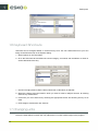
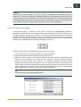
1.2 Starting up the program
Imposition refers to an arrangement of pages on a sheet so that they are arranged in the correct
sequence when the sheet is printed, folded, assembled and trimmed. FASTIMPOSE greatly simplifies
the procedure for imposing a book, using a wizard to quickly configure the general settings of the
imposition for the whole book allows the user to change settings in an interactive way.
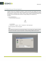
Procedure
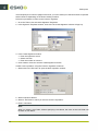
1. Open FASTIMPOSE by:
• Double clicking the startup icon
on the desktop.
• Clicking Start > Programs > Esko > FastImpose > Esko FastImpose
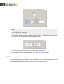
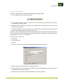
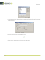
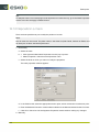
The New Imposition window will appear.
Note:
When creating an imposition via the Imposition Wizard or when starting from a Blank Imposition,
the mode of Job folder in which the imposition is saved (including subdirectories) is used.
8
FastImpose
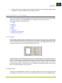
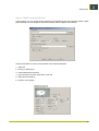
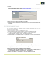
2. Select the tool you want to use for creating a new imposition job:
• Select Imposition Wizard if you want to receive guidelines on how to create a basic imposition
job.
• Select Template if you want to create a reoccurring job that follows a previously defined
template.
• Select Blank Imposition for a flatwork job.
3. Select a JobFolder (for FastImpose Server) or Folder (for FastImpose StandAlone) in which you
want to store the imposition.
4. Enter a Job Name.
5. Click OK. Depending on the selected tool, a different window will appear.
For more information on new impositions we refer to the chapter: Create an imposition.
1.3 GRS versus PDF mode
Only for FastImpose Server
In FastImpose Server, you have the possibility to handle both GRS and PDF based impositions.
As in Automation Engine, we follow the mode model, where the entire system is put in either
Normalized PDF or GRS mode.
Here you'll find more specific information on:
• Modes
• References
• Marks
• Templates
1.3.1 Modes
As with the other editors, FastImpose can handle both GRS and Normalized PDF files. The editor
mode is dictated by the Job.
• When opening an existing GRS imposition with the system mode in PDF, the editor switches to
editor GRS mode.
9
1
1
FastImpose
• In editor GRS mode, it is impossible to add Normalized PDF pages or PDF marks.
• In editor PDF mode, it is impossible to add GRS pages, but it is possible to have both Normalized
PDF as well as GRS/LC marks.
• If there is no mode specification in the IMP file (files saved by FI2.3 and older), GRS mode is used.
• When creating a new imposition from a template, the template mode is used.
• When creating an imposition via the Imposition Wizard or when starting from a Blank Imposition,
the mode of Job folder in which the imposition is saved (including subdirectories) is used.
• If you don't work in a Job folder, PDF mode is used.
Tip:
If no job is open, you can switch modes by selecting “Switch to GRS/PDF Mode” in the Tools menu.
1.3.2 References
Imposition files that have been created prior to Scope 3 contain references to GRS files. They can
refer to page content in the page list, and they can refer to marks (on the different levels: sheet,
signature, page, …).
• For what concerns the page content, we now make a distinction between IMP files that refer to
GRS files ( or the so-called GRS-IMP files), and IMP files that refer to Normalized PDF files (PDFIMP files).
• Marks will behave in the same way as in the other editors. This implies that it is perfectly possible
for a Normalized PDF imposition to contain “textual” references to GRS. They can only exist
however when referring to marks.
1.3.3 Marks
• As mentioned above, GRS-referring marks can still be used in a Normalized PDF imposition.
However, we also support marks that refer to Normalized PDF files. However, as there exist “LC”
uncolored marks in GRS mode which cannot be represented as Normalized PDF files, we must
work around that limitation. Therefore we must adapt FastImpose to accept mono-colored files
as marks, and treat them as if they are uncolored.
• Configuration-wise, there is no need to have separate folders for GRS/LC and Normalized PDF
marks. They can co-exist in the same folder as their file extension allows keeping them apart.
1.3.4 Templates
Just like imposition files, templates also exist in two flavors. They are either GRS templates that
have been created from within FastImpose in editor GRS mode, or PDF templates created when
FastImpose is in PDF mode.
• GRS and PDF templates will be stored in separate folders, depending on their mode. This allows
forcing the rule that FastImpose in editor GRS mode can only work with GRS templates.
• When FastImpose is in editor PDF mode, it can only handle PDF templates.
• Templates that are created when FastImpose is in PDF mode can only be saved as PDF templates.
As a consequence, it is possible to start FastImpose for a new job in PDF mode, based on a
GRS template.
10
FastImpose
• In editor PDF mode, the configuration tool in FastImpose allows you to specify both GRS template
(“Templates”) and PDF template (“Scope Templates”) folders.
1.4 Imposition Concepts
There are six important elements that determine the composition of an imposition job. Each element
needs to be specified, so that FASTIMPOSE can create the imposition of your choice.
This chapter contains the following topics:
1. Content
2. Sections
3. Signature
4. Sheet
5. Plate
6. Print group
• Imposition versus Flatwork
• Global versus Local level
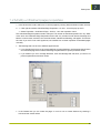
1.4.1 Content
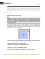
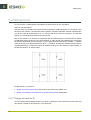
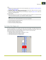
Finished Page: A finished page is a single page in an incoming file. It is the net format, in other words,
the part of the sheet that remains after trimming. In the picture below, the page is displayed as a white
area, the dimensions of which are indicated by Width and Height. In BackStageEdit, the dimensions
of a page in the .grs file can be viewed in the Document Set-up.
Unfinished page: An unfinished page is the part of a sheet that appears as one printed item to the
reader. It is the front view of a folded signature. Usually, the individual pages of a book are unfinished
pages. An unfinished page could be considered the gross format of a book, whereas a finished page
is the net format. Unlike a finished page, an unfinished page also includes margins, which will be
trimmed during finishing. In the above picture, the margins are indicated by Head, Foot, Front and
Back, the unfinished page by the thin gray line.
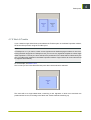
1.4.2 Sections
A section is a printed sheet that consists of a number of pages, so laid out that they will fold and
bind together as a section of a book. It is the smallest physical unit of a book. FASTIMPOSE offers
11
1
1
FastImpose
you the possibility to create a signature containing more than one section. This principle is called
Multisection.
1.4.3 Signature
A signature is that part of the printed sheet that is folded into one or multiple sections. The pages
are ordered, oriented, and numbered so that they are arranged in the correct sequence after folding
and trimming. It is possible to assign different signatures to one sheet. This principle is called
Multisignature. By default, FASTIMPOSE positions a signature in the middle of a sheet, horizontally
as well as vertically. You can adjust this any time by simply modifying the signature properties or by
repositioning the signature interactively.
1.4.4 Sheet
A sheet is a piece of paper with a front and a back. It is possible to apply a single sided signature to a
sheet, which implies that the front and back of the signature will appear on the same side of the sheet.
1.4.5 Plate
Whenever you create an imposition job, you will be asked to indicate the type of press you work with.
Depending on the kind of press, sheet fed or web fed, the sheets will be positioned on the plate.
In the case of a web-fed press, the sheets are by default centered in the middle of the plate. If you
indicated sheet-fed press, you will be asked to enter the distance from the border of the sheet to
the border of the plate. By default, this distance is set to 50 mm. It goes without saying that you can
always modify these settings, both for sheet fed and web fed presses.
Note:
For sheet fed presses, offset Y indicates the distance between the border of the paper and the border
of the plate. For web fed presses, offset Y indicates the distance between the border of the plate
and the center of the paper. If you enter offset Y = 0, then the center of the paper will be positioned
on the border of the plate.
1.4.6 Print group
A print group is the set of plates that you need to print one sheet. It can consist of only 1 plate, but
most of the time several plates will make one print group, depending on the number of separations,
positioning of the signature, etc. The number of sheets in a print group can be changed for each
print group by changing the signature.
The multiweb functionality is a support for multiweb presses. Multiweb presses use multiple webs of
paper for one pass. Since these rolls of paper are folded as a single unit but are printed by separate
plate sets, this will have significant impact on the imposition.
12
FastImpose
Multiweb signatures are saved as separate items and used in the creation of a book, which then
automatically becomes a multiweb job.
1.4.7 Imposition versus Flatwork
The basic definition of an imposition is an assembly of pages on both sides of a press sheet. This
is what distinguishes imposition from flatwork. A flatwork job consists of sheets that have only been
printed on one side. FASTIMPOSE offers you the possibility to create both imposition and flatwork
jobs in an easy way.
1.4.8 Global versus Local level
The global imposition level is represented in FASTIMPOSE by the Master level. Modifications made
to this level will affect all underlying levels. Oppositely, changes made to an underlying level will not
influence the settings of the Master.
How can you see that local changes have been made? In the Preview pane of the Sheet List View,
three different icons can appear to indicate that the local level of a certain sheet or print group differs
from the global (Master) level:
indicates modifications on sheet level.
indicates modifications on signature level.
indicates modifications on unfinished page level.
If you modify the properties of the Master, all underlying levels which have not yet been changed
locally will automatically take the new values. Levels that had already been changed locally will keep
their local values.
When properties of a selected element have been modified locally on a certain level, then the
properties of that element can only be changed on the same or an underlying level.
In the properties dialogs, two buttons can be used to influence the settings:
• The Reset button in the properties dialogs makes sure that the settings of the nearest specified
upper level will be applied to the sheet or page selected. If no other local changes have been
made, the settings of the Master will be applied.
• The Apply to Master function implies that local settings will be applied to the global level (Master),
which means that all levels will be changed, except for those that already differed from the Master.
13
1
1
FastImpose
1.5 Using Templates
A template determines the basic structure of a document and contains basic document settings,
such as marks, margins, signatures, etc. A template is designed as a personal building stone for
creating new jobs. By saving a template as default template, it becomes a personalized standard
template. You will be able to reuse it each time you create a similar job. It might be useful for e.g.
weekly issues of a magazine. FASTIMPOSE offers you the possibility to create all kind of different
templates, such as Signature templates, Plate, Assembly and Imposition templates.
FastImpose Server uses centrally stored templates, whereas FastImpose Standalone works with
local templates.
This chapter contains the following topics:
•
•
•
•
Creating templates
Saving changes to a template
Stored information
Report templates
1.5.1 Creating templates
Creating a template is in fact nothing more than creating (and saving) an imposition with a number of
personal settings. Save these settings in a template once and you won't have to redefine them over
and over again each time you decide to make an identical or similar imposition.
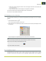
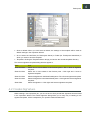
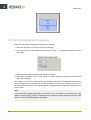
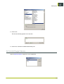
You can find all previously created templates in the Tools menu.
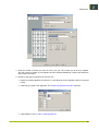
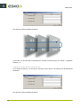
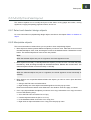
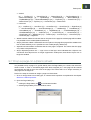
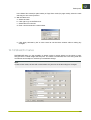
Use template dialogs to create, edit, delete or rename templates.
Click:
New to open the Create Signature, Plate or Assembly dialog and create a new template.
Edit to open the Signature, Plate or Assembly dialog and make modifications to the selected
template.
Copy to make a copy of the selected template.
Delete to remove the selected template from the list.
Rename to enter a new name in the Rename template dialog.
Browse to use an external file as a template.
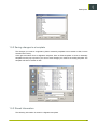
This is an example of the Signature Templates dialog.
14
FastImpose
1.5.2 Saving changes to a template
The changes you make to a signature, plate or assembly template are not saved on disk, but are
stored in the memory.
Click right and select Save as Signature template, Save as Plate template or Save as Assembly
template from the pop-up menu if you want to save changes you made to an existing template. The
template will then be saved on disk.
1.5.3 Stored Information
The following information is stored in a Signature template:
15
1
1
FastImpose
• type: Normal or Cameron
• for Cameron: the number of columns
• for the Normal type: the number or rows, columns, webs, and sections
• stitching method: Latin or Oriental
• page numbering
• overall position of trim, fold, and bleed marks
• bottling factor
• montage settings
The following information is stored in a Plate template:
• plate size
• plate type: sheet-fed or web-fed
• paper position
• gripper info
• way of backing up
• plate marks
The following information is stored in an Assembly template:
• assembly method: Perfect Bound, Saddle Stitch, Special or No Binding
• assembly marks
• in case of Special: number of sections
• in case of Special: possibility to apply creep settings on section level
• in case of Special: possibility to indicate the amount of pages per section and to modify the
section inserts
The following information is stored in an Imposition template:
• all imposition settings entered via the wizard
1.5.4 Report Templates
Only for FastImpose Server
• Introduction
• Using report templates
• Report templates and Automation Engine
Introduction
A Sheet Report shows an imposition sheet by sheet in a customizable schematic view, which makes
it valuable for e.g. the finishing department.In FastImpose the Sheet Report feature is accessible
through the Sheet Report View. On the Automation Engine side, a task was added called 'Create
Imposition Sheet Report' which creates those reports as PDF files based on information loaded from
the imposition file. Using Automation Engine ticket chaining the generated reports can also be printed
automatically.
Each Sheet Report consists of two main parts:
1. a Sheet Report template, which is a PDF or GRS file
2. content dynamically generated by FastImpose (page layout on a sheet with dimensions)
The creation of the Sheet Report template is fully controlled by the user. The Sheet Report template
can contain static elements like fixed texts, logos, etc. and dynamic elements, also known as
SmartMarks. The latter define what kind of information needs to be placed at what position. You can
add all kinds of information to the report such as order number, customer related data, imposition
data (page, sheet numbers, page dimensions, etc.), and specific printer related information like ink
16
FastImpose
names, and many more. When outputting the imposition the dynamic elements in the template are
replaced by the actual values for that file.The dynamically generated imposition content itself is of
course not controlled by the user, only the position and the size of it. The content consists of a semiproportional view of the signatures on a sheet with an indication of page numbers, page sizes, etc.
The Sheet Reports bring two important benefits. Firstly, they allow an external check of the imposition
parameters by somebody who has no access to FastImpose. Errors such as wrong inks being used,
trims being too small or too large, all sorts of sizes being wrong, etc. can be easily detected by a
customer service representative. Secondly, the reports offer an easy way to communicate the same
information from prepress to the press room and the finishing room in a human-readable fashion.
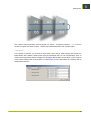
Using report templates
FastImpose comes with a number of report templates for both PDF and GRS modes. An arbitrary
single PDF/GRS file can be used as a report template, but you can also make your own templates by
manually creating rectangles and other objects in PackEdge. These special objects, like e.g. Named
Objects and Text marks, can be created in the report template, but will be searched and handled
by FastImpose separately.
• The rectangle with annotation (Object Name in PackEdge) "report_area" defines the rectangle
area, where the sheet schematic diagram (directly generated by FastImpose) will be placed and
scaled too. It is possible to have both sides of one sheet at one side of a printed report. To achieve
this, simply create two rectangles (instead of one) and name them "report_area_f" (for front side)
and "report_area_b" (for back side).
• A Text Mark with SmartName(s) defines dynamic text, which is resolved by FastImpose when
exposing a sheet.
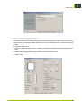
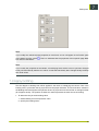
You can select a report template in the Report Template group of the Sheet Properties dialog box or
by clicking 'Report Templates' from the Tools menu.
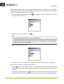
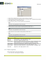
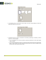
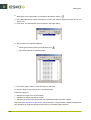
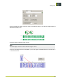
Standard templates that come with FastImpose are:
17
1
1
FastImpose
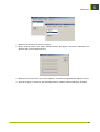
The sheet diagram that is displayed in the Sheet Report View will always be displayed, even if you
did not select a report template. If this is the case, or if the selected file does not exist, FastImpose
will behave as if the default (blank) template is used. In this case the size of the report template will
be A4. If a template is selected, other than the default template, the size of this report is defined by
the size of the page in the template.It is not mandatory to add extra objects, as the report template
can easily be a blank page. Whether or not you want to refine this template, fully depends on your
personal requirements.
18
FastImpose
Caution:
FastImpose specific SmartNames have to be typed in by hand when the Printed Report template
is made in PackEdge.
Note:
Printed reports created in a flatwork job will not show dimensions along the signature(s) sides.
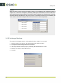
Report templates and Automation Engine
It is possible to print out the Sheet Reports from an imposition using the 'Create Imposition Sheet
Report' ticket in the Automation Engine Pilot. This task converts the imposition file into a PDF of which
the number of pages equals the number of sheetsides in the imposition file. The size of generated
PDF is determined by the Sheet Report template the same way as in FastImpose Sheet Report view.
19
1
1
FastImpose
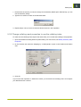
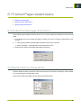
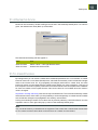
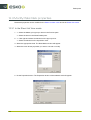
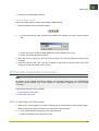
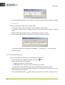
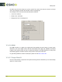
1.6 Keyboard Shortcuts
Shortcuts can be changed, added, or removed at any time. You can create shortcuts to your own
liking via the Shortcuts tab in the Options dialog.
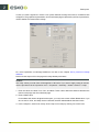
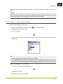
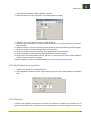
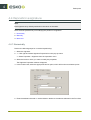
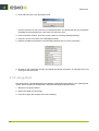
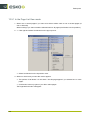
1. Select Options in the Tools Menu.
2. Go to the Shortcuts tab and select the correct category, command, and accelerator to check or
set the desired shortcut key.
1. Check if the right platform (Esko Classic, Macintosh or Windows) is selected.
2. Select the category and command for which you want to create or adapt a shortcut. An existing
shortcut key will be shown.
3. Customize your own shortcuts by checking the appropriate boxes and entering the key to be
used.
4. Click Assign to activate the new shortcut.
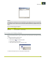
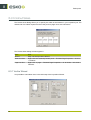
1.7 Changing units
Follow the steps below to switch the unit (millimeters or inches) used throughout the program.
20
FastImpose
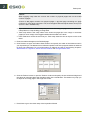
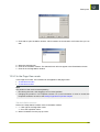
1. Go to the Tools menu.
2. Select Options.
3. In the General tab, select the appropriate unit from the dropdown list.
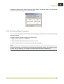
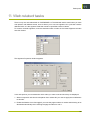
1.8 Shuttle
Shuttle allows to submit the current job to a workflow queue, and to monitor jobs running on the
server.
In PackAdge you can only submit to the Automation Engine 10 server to which the application is
connected using the preferences dialog.
All Shuttle functionality can be found in File > Launch Workflow and Windows > Shuttle
A full explanation on Shuttle can be found in the Shuttle documentation, available on the EskoArtwork
Documentation DVD.
21
1
2
FastImpose
2. Create an imposition
There are three possible ways of creating an imposition. First of all, you can use the Imposition
Wizard, which will help you to create a basic imposition in four simple steps. Secondly, you can start
from a blank imposition and personalize your settings afterwards. A third way is to start from an
imposition template which you previously saved.
This chapter contains the following topics:
1. Create an imposition
2. Create an oriental imposition
3. Start from a Blank Imposition
4. First View: Sheet List View mode
2.1 Create an imposition
An imposition can be created in a number of ways. This chapter explains the possible workflows:
This chapter contains the following topics:
• Introduction
• Use the imposition wizard
2.1.1 Introduction
There are three ways of creating a new imposition. Either you work with the Imposition Wizard, or
you start from an imposition you previously saved as an Imposition Template. If you want to start
from scratch or create a flatwork job, choose for a Blank Imposition.
Follow this procedure to create a new imposition:
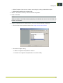
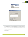
1. Select New in the File menu to open the New Imposition dialog.
2. • Select Imposition Wizard if you want to receive guidelines on how to create a basic imposition
job.
22
FastImpose
• Select Template if you want to create a reoccurring job, using a predefined template.
• Select Blank Imposition for a flatwork job.
3. Select a Job Folder in which you want to store the imposition.
4. Enter a Job Name.
Note:
When you select a Job Folder, without specifying a Job Name, the name of the Job Folder will
be taken as Job Name.
5. Click OK. Depending on the selected tool, one of the following dialogs will appear:
• The first step of the Imposition Wizard. See Using the Imposition Wizard.
• The Select template dialog.
• Select an imposition template from the list.
• Browse to an imposition template that is not stored locally.
23
2
2
FastImpose
• The Sheet List View mode. You'll have an “empty” job to which you can add pages by selecting
Add Unfinished Page or Apply Signature from the Imposition menu.
2.1.2 Use the Imposition Wizard
This chapter tells you how to create a basic imposition in four simple steps.You can navigate through
the different wizard dialogs (steps) by clicking the Back or Next buttons. Click the Finish button when
you are ready to apply your settings.
1. Step 1: Signature window
2. Step 2: Assembly window
3. Step 3: Page Properties window
4. Step 4: Plate Properties window
5. Save as template
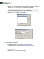
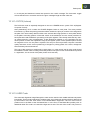
Step 1: Signature window
This window allows you to define the signature information. This information is important in ensuring
that the pages are in the correct order after the job has left the finishing department.
The first step of the Imposition Wizard may vary, depending on the type of signature (multisection
or not) selected.
24
FastImpose
1. Enter the number of sheets you want to use in your job. The number you fill in here, together
with the number of pages in the signature and the selected distribution method will determine
the number of sections.
2. Decide on the type of signature you want to use.
• Select an existing signature from the list, or click Browse to use a signature that is not stored
locally.
• Click New to create a new signature. The Create New Signature window will open.
• Click Modify to view or edit an existing signature.
25
2
2
FastImpose
Note:
Although FASTIMPOSE offers the possibility to position multiple signatures on one sheet, it is not
possible to do so immediately via the Imposition Wizard. You can add extra signatures afterwards,
via the Add Signatures window.
Note:
All signatures chosen will by default be positioned in the center of the sheet. No rotation will be
given. Change the position and rotation of the signature via the Signature Properties window.
Note:
Signatures are automatically attributed a recto and a verso side. If you want to obtain a single
sided or flatwork imposition, you can still change this afterwards via the Sheet Properties window.
3. Click Next.
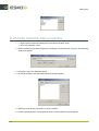
Step 2: Assembly window
Select an Assembly template from the dropdown list. If you have not yet created assembly templates,
select Untitled, which is the default template.
Note:
FASTIMPOSE also offers you the possibility of Mixed binding, i.e. a combination of saddle stitching
and perfect binding. It is, however, not possible to create this type of assembly in the Imposition
Wizard. After having finished the wizard, you can change the assembly settings via the Assembly
Properties dialog.
26
FastImpose
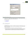
Step 3: Page Properties window
This window will ask you to enter the dimensions of the finished page, as well as the size and position
of the text area. For the page, default values are set, the text area dimensions you will have to specify
yourself.
This window allows you to:
• Enter the unfinished page specific variables (e.g. distances between unfinished page and trim
box).
• Enter finished page properties (e.g. determine the default foldout size)
• Define creep.
27
2
2
FastImpose
In case you used a signature in which a non-system defined montage was used, a modified screen
will appear. The graphical representation of the unfinished page is replaced by the list of parameters,
used to define the customized montage.
For more explanation on Montage definitions we refer to the chapter Use a personal montage
definition.
Perform these steps to fill in the page and creep-related parameters.
Caution:
The creep values you enter here will be applied on all books. If you want to apply creep per section,
use the procedure via the Imposition menu > Properties > Assembly > Select a section > Creep.
1. Enter the values for Head, Foot, Front, and Back. These values define the distance between the
final trimmed page and the unfinished page.
2. Enter a Bleed value.
For booklets that need to be glued at the spine, you may have to enter a Back Bleed value. If you
do not enter a value, and keep the box checked, the back bleed defaults the bleed value.
3. In the Creep box, select Inner creep, Outer creep or No creep by clicking one of the icons.
28
FastImpose
• Inner creep: the thickness of the paper is compensated by moving the inner pages of a booklet
towards the spine of the book.
• Outer creep: the thickness of the paper is compensated by moving the outer pages of a booklet
away from the spine of the book.
The creep origin option allows you to indicate the asymmetric creep, also known as 'shingling'.
The asymmetry is caused by the gripper, which holds the paper during folding. As a consequence,
this side has no creep, but the creep on the opposite side is applied twice. This implies that the
fold (spine) position is also moved towards the gripper. Click the correct option; left, center or
right to define the origin.
Now there are three different methods of applying creep: offset, scaling and a combination of
offset and scaling.
• Use Offset moves pages according to its creep value.
• Use Scalingmoves one edge of the page (the inner for outer creep and the outer for inner
creep) and scales the page (in horizontal direction only) so the opposite edge is not moved.
• Combine offset and scaling combines the two methods. When the creep to be applied is small
enough, the offset method is used. When the offset (= creep value) exceeds a given threshold
("Transposition Point"), on top of moving, scaling is used to make sure that the relevant page
edge doesn't "cross" the given threshold. This implies that the "Transition Point" determines
the maximum allowable shift of the whole page (without scaling).
• The Transition Point value should not be bigger than the bleed value (backbleed for inner
creep). However, now it is possible to enter arbitrary non-negative values. If this value is bigger
than the (back)bleed, a message box will appear, leaving the user the option to "Leave Entered
Value", "Use Bleed Value", or "Change Value".
• If you selected Inner or Outer creep and you know the paper thickness, enter its value in
the Paper Thickness field. The corresponding creep offset or creep scaling per page will be
calculated automatically.
29
2
2
FastImpose
Caution:
When applying creep take into account the number of physical pages and not the actual
number of pages.
A book of 488 pages contains 244 physical pages, a physical page containing two page
numbers. So, if this book measures 1 inch, then the paper thickness equals 0.0041 inch (1/244
and not 1/488 = 0.00205 inch).
• If you selected Inner or Outer creep and you know the creep per page, enter its value in the
Creep Offset or Creep Scaling per Page field.
• Total creep offset is the creep offset of the innermost pages (for inner creep) or outermost
pages (for outer creep) of the biggest saddle stitch booklet in the book.
• Peak scale factor works the same way as 'Total creep offset' but has an impact on the scale
factor.
4. Enter the width and height of the Finished page.
5. Click Foldouts to open the Foldout Sizes window and specify the width of the foldouts used in
your imposition job. The default size of a foldout equals the size of the page the foldout is attached
to minus two millimeters. For more information on foldouts we refer to the following chapters:
Add foldouts to a signature, Add or Remove foldouts and Change foldout sizes.
6. Click the Textbox button to open the Textbox window and specify the text width and height and
the values for head and back that should be taken into consideration. The textbox may help you
to adjust an incoming page in the Page View mode.
7. Press Next to go to the fourth step of the Imposition Wizard.
30
FastImpose
Step 4: Plate Properties window
In this window you can set the sheet properties for the Master level of the imposition.Select a plate
plate template from the dropdown list and all settings will be adapted automatically.
Click the Edit button to find more properties of the selected template.
1. plate size
2. the way of backing up
3. marks attatched to the plate
4. type of press to be used: sheet fed or web fed
5. paper size and position
6. position of the gripper
31
2
2
FastImpose
Press the Reload button if you want to return to the plate template’s original features and values that
are stored on the hard disk of your computer.
Select a report template from the dropdown list. A Sheet Report shows an imposition sheet by sheet
in a customizable schematic view. For more information, please refer to the chapter on Reports
templates.
Save as template
2.2 Create an oriental imposition
Creating an oriental imposition is almost identical to creating a western imposition. Two things,
however, are different. First of all, the oriental signature will have to be created, and secondly, the
page list has to be made oriental. Two simple actions that are explained in the following chapters:
• Create a signature
• Modify the stitching position
2.3 Start from a Blank Imposition
If you have a small job of a large circulation, you might want to put several copies on one single
sheet. The best option is to start from a blank imposition and use the Step and Repeat tool to help
you to multiply the job in an easy way.
This chapter explains how to create a blank imposition and provides you with some additional
information on how to proceed.
• Create a blank imposition
• Add an unfinished page
• Step and repeat
2.3.1 Create a blank imposition
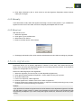
1. Activate the New Imposition window by:
•
clicking the New Imposition
icon.
• selecting New from the File menu.
• using the shortcut: Ctrl+n
32
FastImpose
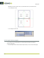
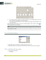
2. Select the Blank Imposition radio button.
3. Select the Job Folder in which you want to store the imposition.
4. Enter a Job Name.
Note:
When you select a Job Folder, without specifying a Job Name, the name of the Job Folder will
be taken as Job Name.
5. Click OK.
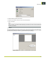
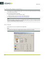
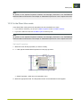
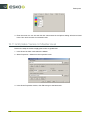
You will immediately enter the Sheet List View mode. In the Preview pane (left), you will see that your
imposition job consists of one sheet only. The Sheet Details pane (top right) doesn’t show any details
yet. The Assembly Details pane (bottom right ) shows the words: No Binding.
33
2
2
FastImpose
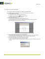
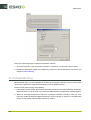
2.3.2 Add an Unfinished Page
One of the first things we are going to do is adding an unfinished page.
The unfinished page is the area that covers the trimmed page and the margins.
1. Go to the Sheet View mode by:
• selecting View mode > Sheet from the View menu.
• clicking the Sheet View icon
in the Selector toolbar.
• using the shortcut: Ctrl+2 (default setting)
2. Add an Unfinished Page by:
• selecting Add Unfinished Page from the Imposition menu,
• right-clicking the sheet and selecting Add Unfinished Page from the pop-up menu.
A blank page will pop up at the center of the sheet.
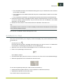
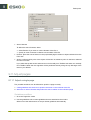
3. You can change the properties of the unfinished page by:
• right-clicking the page and selecting Unfinished Page Properties from the pop-up menu.
• selecting Properties > Unfinished Page > On the… from the Imposition menu.
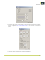
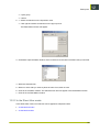
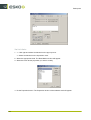
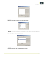
4. Put the unfinished page in the correct position on the sheet:
• Click left to select and drag the page to its new position.
• Select the page, click right and select Move from the pop-up menu. The Move window will
pop up:
34
FastImpose
• Select Move from the File menu.
• Select the page, click right and select Unfinished Page Properties > On this unfinished page
from the pop-up menu. In the General tab you can modify its position.
• Select Properties > Unfinished Page > On this unfinished page from the Imposition menu.
Tip:
The above explanation of adding an unfinished page can be avoided by simply dropping (.grs) pages
directly on the sheet. For more information, please refer to the chapter: Drop a page on a (blank)
sheet.
2.3.3 Step and Repeat
If you have a small job of a large circulation, you might want to put several copies of one job on
one single sheet. Step and repeat is a feature that helps you to multiply the job in an easy way. This
option can be used for any selected element, such as a page, a mark, etc.
• Horizontal Count: Indicate how many times you want the selected object to appear horizontally.
• Vertical Count: Indicate how many times you want the selected object to appear vertically.
35
2
2
FastImpose
• Horizontal Step: Indicate the horizontal distance between the center of the original object and the
center of the copied object.
• Vertical Step: Indicate the vertical distance between the center of the original object and the center
of the copied object.
The Step and Repeat dialog will appear in:
Place
How
Menu bar
Click Edit > Step and Repeat.
Sheet View
Right click the selected object > Step and Repeat.
Note:
For signatures, this option will only appear when you start from a blank
imposition.
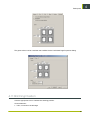
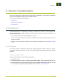
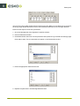
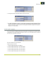
2.4 First View: Sheet List View mode
Independent from the tool used to create the imposition, the Sheet List View mode will always be your
first view on the new imposition. This view mode is the basic view mode from which you have access
to all tools and techniques to mould an imposition into its definitive shape. It gives an overview of
the basic structure of the imposition.
In the Sheet List View mode, three panes can be distinguished:
1. the Preview pane on the left.
2. the Sheet Details pane in the top right corner.
3. the Assembly Details pane in the bottom right corner.
36
FastImpose
In the Preview pane, three different icons can appear to indicate that the local level of a certain sheet
or print group differs from the global (Master) level (see Global versus Local level):
indicates modifications on sheet level.
indicates modifications on signature level.
indicates modifications on the unfinished page level.
If you modify the properties of the Master, all underlying levels which have not yet been changed
locally will automatically take the new values. Levels that had already been changed locally will keep
their local values.
When properties of a selected element have already been modified locally on a certain level, then
the properties of that element can only be changed on the same or an underlying level.
Settings can be influenced via the different properties windows. Two buttons play an important part:
• The Reset button makes sure that the settings of the nearest specified upper level will be applied
to the sheet or page selected. If no other local changes have been made, the settings of the
Master will be applied.
• The Apply to Master function implies that the settings that have been modified on local level will
be applied to the global level (Master), which means that all levels will be changed, except for
those that already differed from the Master.
37
2
3
FastImpose
3. Basic Actions
This chapter contains the following topics:
• Select or deselect
• Measure an object
• Zoom In / Out
• Pan
• Renumber pages
• Measure ink density
• Create a layer
• Copy or Remove a layer
3.1 Select or deselect
To be able to manipulate an object you first have to select it with the Select tool
find in the Interactive toolbar on the left of the screen.
which you can
• Place the cursor on the object and click the left mouse button if you want to select an individual
design object. The object will appear in red to show that it has been selected. You can now
manipulate or modify it.
• If you want to select all design objects within an area, place the cursor outside the objects you
want to select. Click left and drag the mouse to draw a box around the design objects. Release
the mouse button. The objects will appear in red to indicate selection.
• Press the Shift key and left click the object to add an object to a selection.
• Press the Shift key and left click the object to remove an object from the selection. The object
will appear in black.
• If you want to deselect all design objects within an area, place the cursor outside the selected
area. Click the left mouse button. The objects will appear in black to indicate deselection.
This function is available in Sheet and Page View mode.
3.2 Measure
The Measure tools calculates the distances between any two points in the work area. It also offers
you an easy way of measuring horizontal and vertical dimensions of an object.Follow the steps below:
1. Click the Measure tool
38
in the Interactive toolbar. The measure window appears:
FastImpose
• The coordinates in the top row indicate the starting point of your measurement, seen in relation
to the center of the plate.
• The coordinates in the middle indicate the end point of measurement in relation to the center
of the plate.
• The coordinates in the bottom row represent the absolute horizontal and vertical distances.
2. Click left and hold to draw a rectangle around the object whose dimensions you want to measure
or a line to measure a certain distance. As you move the cursor, the coordinates in the middle
and bottom row will change.
3. Release the mouse button. Final measurements are indicated in the bottom row.
Tip:
It is advised to work in the Cross or Contours display mode because the Measure tool then snaps
to any contour present in the job.
This function is available in Sheet and Page View mode.
3.3 Zoom In / Out
The zoom commands allow you to magnify or reduce the display of any area in the file up to x times
the actual size.
•
Use the zoom icon:
Left-click and hold to draw a rectangle around the object you want to zoom in on. Release the
mouse button. Left-clicking zooms further in on the selected area.
• Select the zoom tool and click the sheet/page to zoom in. Use Alt-click to zoom out.
• Enter a zoom percentage in the zoom box
of the Selector toolbar.
• Use the function keys: press F5 to zoom in, F6 to zoom out, F8 to zoom in once (default settings).
• Select the appropriate zoom command from the View menu:
To view the complete imposition job, make it fit into the window by:
• pressing the F9 key (Esko shortcut), or Ctrl+H (Windows or Macintosh shortcut).
• selecting Fit in Window from the View menu.
If you want to return to the previous view:
39
3
3
FastImpose
• press the F10 key.
• select Previous View from the View menu.
This function is available in Sheet and Page View mode.
Tip:
You can switch between Esko and Standard shortcuts for Macintosh and Windows as follows:
3.4 Pan
The Pan tool allows you to pan the preview window.
1.
Click the Pan icon
2. Left-click the area of interest and drag the cursor to where you want this area to appear on the
screen.
3. Release the mouse.
Tip:
• Press F7 to use the Pan tool once (the tool button appears in red).
• Press F7 twice or click the Pan tool once if you want to use the tool repeatedly until it is deactivated
(the tool button appears in blue).
• If you press F7 three times you return to the tool you were previously working with.
This function is available in Sheet and Page View mode.
3.5 Renumber pages
The Renumber tool offers you the chance to change the page numbering manually.
Note:
This tool can only be used in an imposition for which the no binding assembly method is selected.
1.
Clicking the Renumber tool icon
makes the following dialog appear:
Now you can change the numbering of the pages in the Sheet View manually.
2. Enter the first page number you want to appear in the Current page number field.
• Left-click a page to assign the number in the Current page number field. The number in the
box will increase by 1.
40
FastImpose
• Right-click a page to assign the number in the Current page number field. The number in the
box will decrease by 1.
• Keep clicking the pages until all the pages of the signature are assigned.
You can also simply enter the appropriate page number in the edit fields.
This function is only available in Sheet View.
3.6 Measure ink density
The Densitometer tool allows you to measure the separated ink percentages of a color at a specific
position.
1.
Click the Densitometer tool
The cursor assumes the shape of the tool icon.
2. Click a color area. The densitometer window will show the color and the percentages for each
ink separation.
The percentages for ink separations given here will be those of the final films.
Tip:
If you click and drag the densitometer, the percentages are updated automatically.
Make sure you are working in the Extended View mode
if you want to obtain correct values.
3.7 Create a layer
FASTIMPOSE has a layer feature, which is useful for jobs that contain multiple versions. A typical
example is a job that has to be printed in various languages. Additional layers can be created for
41
3
3
FastImpose
the different languages, allowing for the complete job to be built in one imposition file. In addition,
mock-up elements and marks are each added to a separate layer. This allows you to easily select,
modify, view and output those elements separately.
1.
2.
Open the Layer Gallery by clicking the icon
The Layer Gallery will pop up:
in the Selector toolbar at the bottom of the screen.
Create a new layer by clicking this icon
Note:
• A new pages layer automatically creates a new page list.
• A new layer appears on top of the selected layer. It is, however, not possible to create a layer
on top of the trimboxes or marks layer. The order of all underlying layers can be changed by
dragging them to their correct position.
3. Enter the name of the new layer.
4. Select the layer to which you want to add pages in the Layer Gallery or in the Layer Selector.
Each layer can be marked by the following elements:
•
•
42
The eye
has to do with visualization. When a layer is marked with an eye, each element of the
layer will be visible on the screen. Oppositely, the absence of the eye indicates that the layer is
not visible.
When a layer is marked with a lock
, elements of that layer cannot be modified. Oppositely, the
absence of the lock indicates that each element of the layer can freely be selected and altered.
FastImpose
When you expose the file in Automation Engine, you have the opportunity to select which layer to
expose.
Caution:
When using layers, please make sure that the background layer is always the bottom layer. This to
avoid incorrect output when working with variants in Automation Engine.
3.8 Copy or Remove a layer
Follow this procedure to copy a layer:
1.
Open the Layer Gallery by clicking the icon
in the Selector toolbar.
2. Select the layer you want to copy.
3. Click the copy icon
to add a new layer as a copy of the selected layer. The copied layer will appear on top of the
original layer.
Note:
• A new pages layer automatically creates a new page list.
• The new layer appears on top of the copied layer. It is not possible to copy the trimboxes or marks
layer. The order of all underlying layers can be changed by dragging them to their correct position.
Follow this procedure to remove a layer:
1. Open the Layer Gallery by clicking the icon
in the Selector toolbar.
2. Select the layer you want to remove.
43
3
3
FastImpose
3. Click the recycle bin
44
FastImpose
4. Signature related tasks
In this chapter explains all possible signature related actions that you can perform. Important in this
chapter is the principle of multisignature, which allows you to position several signatures on one
sheet. It is explained in the chapter Add and Remove a Signature.
This chapter contains the following topics.
• Apply a signature to a sheet
• Create a signature
• Replace a signature
• Reposition a signature
• Group signatures
• Rotate a signature
• Add and remove a signature
• Modify signature properties
• Use a personal montage Definition
• Use gutters
• Modify the stitching position
4.1 Apply a signature to a sheet
When making an imposition, you can replace the signature used on a particular sheet by another
signature. This offers you the possibility to create an imposition, consisting of different types of
signatures. (Also see Add and remove a signature.)
To apply a signature to a sheet or a number of sheets, select the sheets in the Preview pane of the
Sheet List View mode and activate the Apply signature window either by using the menu bar or by
clicking the right mouse button.
4.1.1 Apply Signature
While creating an imposition, it is easy to replace the signature used on a particular sheet by another
signature. This offers you the possibility to create an imposition, consisting of different types of
signatures.
The Apply signature dialog shows you a list of signature templates and offers you the possibility to
browse to signature templates that are stored locally. You can at any time edit existing signatures
or create new ones.
45
4
4
FastImpose
• Signature template: Select an existing signature template from the list or use the Browse button
to select a signature that is not stored locally.
• New: Hit the New button to create a new signature.
• Edit: Hit Edit to make adaptations to the selected signature.
• Reload: Even after having modified a signature, it remains possible to return to the signature's
original features and values that are stored on the hard disk of your computer. Click the Reload
button.
• Reset: When you hit the Reset button, the settings of the nearest specified upper level will be
applied to the sheet that is being modified. If no other local changes have been made, the settings
of the Master will be applied.
The Apply Signature dialog also appears in:
Place
How
Menu bar
Click Imposition > Apply Signature.
Sheet List View
Right click a selected sheet or the Master (if you want to apply the new signature
to all sheets) in the Preview pane > Apply Signature.
Sheet List View
Right click the Sheet Details pane > Signature Properties > Template and select
a new signature from the dropdown list.
Sheet View
Right click > Apply Signature.
4.1.2 Edit unfinished pages
The different tabs of the Signature Properties dialog offer you the possibility to modify individual
pages of the signature.
Modify the unfinished pages as explained below:
1. Indicate the rotation of the pages by clicking the arrows or the corners of the page.
• Modify the horizontal rotation of a column by clicking the arrow on top of the unfinished page.
• Modify the vertical rotation of a row by clicking the arrow on the left of the unfinished page.
• Modify a page individually by clicking one of its corners.
2. Change the page numbering by:
• left-clicking the page. A window opens in which you can select a free number that can be
assigned to that page.
46
FastImpose
Note:
The way page numbers are allocated depends on the stitching method selected. Latin
signatures will consider page 1 to be a right page, Oriental signatures a left page.
Note:
Empty zones can only be assigned in case of a personal montage definition. Please refer to the
chapters Define an empty page and Use a personal montage definition for more information
• typing the desired page number in the page number input box. The page will automatically
turn into a left- or right-handed page, depending on the signature type (Latin or Oriental).
Caution:
If page numbers are not assigned in a logical manner, an error message pops up, saying: “The
signature does not contain a continuous sequence of numbers.” Click Continue and adjust the
page numbers that are not correct.
3. You can add or remove a foldout by right-clicking the page and selecting the option of your choice.
4. In the Trim, Fold, and Bleed tab sheets, indicate the marks that you want to appear on the paper.
• If you want the marks to appear on all pages, indicate them on the Master page. You will see
the marks appear on all pages of the Front and Back.
• If you want to change the marks on one or some particular pages, adapt the pages of the
Front and/or Back.
Pages of which the marks differ from those of the Master appear in blue. Click the symbol
to make the page identical to the Master.
47
4
4
FastImpose
Note:
If you change marks on the Front, the Back will automatically be adapted. This is not the case
if you change marks on the Back.
5. In the Bottling tab click the corner you want to apply bottling to. The little black square indicates
your selection. In the angle field, enter the appropriate degree.
For more information on bottling we refer to the chapter Apply bottling.
6. For an explication of the Montage tab sheet, we refer to the Montage chapter.
4.1.3 Save as signature template
The Save as signature template dialog makes it possible to store the (newly) created signature used
in the imposition job. Give the template a unique name and hit the Save button.
48
FastImpose
• Save as default: When you click Save as default, the settings of the template will be used as
default settings in the Imposition Wizard.
• Go to: Select the JobFolder (for FastImpose Server) or Folder (for FastImpose Standalone) in
which you want to store the template.
• Templates: Clicking the Templates button brings you back to the central templates directory.
The Save as signature template dialog will also appear in:
Place
How
Sheet List View
Select one or more sheets in the Preview pane > File > Save as signature
template.
Sheet List View
Select one or more sheets in the Preview pane > Click right and > Save as
signature template.
Sheet List View
Select the signature in the Sheet Details pane > File >Save as signature template.
Sheet List View
Select the signature in the Sheet Details pane > Click right and Save as signature
template.
Sheet View
Select the signature > Click right and Save as signature template.
4.2 Create Signature
While creating a new imposition job, you do not have to limit yourself the signatures that are listed
in the Imposition Wizard. The Create Signature dialog offers you an easy way of creating a new
signature template, which is adapted to your specific needs and demands.
49
4
4
FastImpose
•
•
•
•
Name: Enter a signature name, which is unique and easy to recognize.
Stitching method: Enable the appropriate button to indicate a Latin or Oriental stitching method.
Type: Select Normal or Cameron from the list.
Rows: Enter the number of rows the signature can be printed in.
Note:
This option is only applicable for the Normal type.
• Columns: Enter the number of columns the signature can be printed in.
• Sections: Enter the correct number of sections (optional). Default value = 1.
Note:
This option is only applicable for the Normal type.
• Webs: Enter the correct number of webs (optional). Default value = 1.
Note:
This option is only applicable for the Normal type.
The Create Signature dialog will also appear in:
Place
How
Menu bar
Click Imposition > Add / Apply Signature > New.
Menu bar
Click Tools > Signature templates > New.
Sheet List View
Right click a selected sheet in the Preview pane > Apply / Add Signature > New.
Select the Master if you want the signature to be applied to all sheets.
Sheet List View
Right click the Preview pane > Signature Properties > Templates > New.
Sheet List View
Right click the Sheet Details pane > Add / Apply Signature > New.
Sheet List View
Right click the Sheet Details pane > Signature Properties > Templates > New.
Sheet View
Right click > Add / Apply Signature > New.
4.2.1 Create a signature
Perform these steps to create a new signature.
1. In the Tools menu, select Signature Template.
50
FastImpose
2. The Signature Templates window appears, click New.
3. Enter the name of the new signature in the Create Signature window.
4. Indicate if you want to create a Latin or oriental signature.
5. Select the type of signature you prefer: Normal or Cameron. For more information on Cameron,
see next page.
6. Enter the number of rows the signature can be printed in. (Only applicable for the Normal type).
7. Enter the number of columns the signature can be printed in.
8. Enter the number of sections (optional). (Only applicable for the Normal type).
9. Enter the number of webs (optional). (Only applicable for the Normal type)
10.Click Create. The New Signature window will open. Or click Cancel to exit the Create Signature
window without making any changes.
Adjust the Signature window as explained above in the Edit unfinished pages chapter.
4.2.2 Add foldouts to a signature
1. Create a new signature as explained above.
2. In the Signature Properties window, right-click the page you want to add a foldout to and select
Add.
4.2.3 Cameron
A certain logic regarding the signature is inherent in the Cameron workflow. One signature can be
applied for the entire book. The essence of this method is that, if you enter the page numbers of one
51
4
4
FastImpose
row and specify the number of pages to the book, you know exactly how the book will be composed.
Select Cameron depending on the kind of folding machine.
Follow this procedure to create a new Cameron signature.
1. Go to the Tools menu and select Signature Templates.
2. In the Signature Templates window, click Add. The Create Signature window will pop up.
3. In the Create Signature window:
• Enter the signature’s name.
• Select Cameron.
• Enter the number of columns.
4. Click Create or Cancel to exit the Create Signature window.
Create a new imposition, using the Cameron signature as follows:
1. Select New in the File menu to open the New Imposition window.
2. Select Imposition Wizard.
3. Select a Job Folder in which you want to store the imposition.
4. Enter a Job Name.
Note:
When you select a Job Folder, without specifying a Job Name, the name of the Job Folder will
be taken as Job Name.
52
FastImpose
5. Click OK.
Select the newly created signature in the first step of the Imposition Wizard. For more information
on the Imposition Wizard, see the chapter:Use the Imposition Wizard.
6. Specify the number of pages in the Page Count input box.
7. Click Next to proceed with the remaining steps of the Imposition Wizard or Finish to see the result
immediately.
4.3 Replace a signature
You can replace a signature on one sheet, but also on several sheet at the same time. Both
procedures are explained below.
A. Perform these steps to replace the signature on one sheet.
1. Select a sheet (in the Sheet List View mode) or a signature (in the Sheet View mode).
2. • Click right and select Signature Properties > On this… from the pop-up menu or:
• Select Properties > Signature > On this… from the Imposition menu.
3. Click the Template tab sheet, which indicates the signature that is currently applied to the sheet.
4. Select a different signature from the dropdown list or create a new signature as explained in the
Create a signature chapter.
5. Click Apply, followed by OK or click Cancel to exit the Signature Properties window without
making any changes.
B. Perform these steps to replace the signature on several / all sheets.
1. In the Sheet List View mode select the sheets to which you want to apply a different signature. If
you want to apply the signature to all sheets of the job, select the Master.
2. Steps 2 to 5 are identical to the procedure for replacing a signature on one sheet.
53
4
4
FastImpose
4.4 Reposition a signature
Note:
Each signature is by default positioned in the center of the sheet.
There are three possible ways of modifying the position of a signature:
1. Numerically
2. Manually
3. Move tool
4.4.1 Numerically
Perform the following steps for numerical repositioning:
1. Select the signature.
2. • Click right and select Signature Properties from the pop-up menu.
• Select Properties > Signature from the Imposition menu.
3. Select the level on which you want to modify the properties.
The Signature Properties window will appear.
4. In the Position tab, select the appropriate anchor point, which will function as reference point.
5. Enter the desired horizontal or vertical offset in relation to the element selected in the From lists.
54
FastImpose
6. Click Apply, followed by OK or click Cancel to exit the Signature Properties window without
making any changes.
4.4.2 Manually
In the Sheet View mode, select the signature and drag it to the correct position. If you modified the
signature on the front of the sheet, the back will equally be adapted and vice versa.
4.4.3 Move tool
With the Move tool:
1. Select the signature.
2. Click right or go to the Edit menu.
3. Select Move from the list.
4. Enter a horizontal and/or vertical offset.
5. Click Apply, followed by OK or click Cancel to exit the Move window without making any changes.
4.5 Link signatures
FastImpose allows you to position signatures in relation to each other. This means that they are
linked, which will cause the dependent signature to move along when the position of the reference
signature is changed (but not vice versa).
Perform the following steps to link signatures:
1. Select the signature you want to link or make dependent (signature 2).
2. Click right and select Signature Properties > Of this sheet from the pop-up menu.
3. Go to the Position tab.
4. In the From object list, select Signature.
5. Position signature 2 in relation to the front or back of signature 1.
6. Position signature 2 in relation to the left, center, or right (for horizontal positioning) or top, center,
or bottom (for vertical positioning) of signature 1.
Caution:
If you reposition the reference signature and one of the borders of the dependent signature coincides
with the plate or paper margin or center, the properties in the From box of the Position tab will
automatically be adapted. If you want to keep the original references, hold down the ALT key while
moving.
55
4
4
FastImpose
4.6 Rotate a signature
Note:
The signature is by default positioned in the center of the sheet with a rotation angle of 0°.
To modify the rotation of a signature:
1. In the Sheet List View mode, select the sheet(s) whose signature(s) you want to rotate.
2. • Click right and select Signature Properties from the pop-up menu.
• Select Properties > Signature from the Imposition menu.
The Signature window will open.
3. Go to the General tab and indicate the appropriate rotation.
4.7 Add or Remove a signature
In this chapter we explain how to add extra signatures to a sheet and how to remove them. This is
where multisignature joins in. Multisignature makes it possible to apply several, different signatures
to one sheet. This means that the signatures you add do not have to be identical to the signatures
that were added previously.
4.7.1 Remove a signature from a sheet
Left-click the signature to select it. You can remove it by:
• clicking the
icon in the Standard toolbar.
• selecting Clear from the Edit menu.
• right-clicking and selecting Delete from the pop-up menu.
56
FastImpose
Caution:
Deleting a signature cannot be undone!
4.7.2 Add Signature
The Add Signature option implies that it is possible to create an imposition job of which the sheets
contain different signatures. This principle is called multisignature.
The Add Signature dialog contains two tab sheets: Signature and Position.
• Template: Click the Browse button to go to the correct templates location or select a template
from the dropdown list.Templates from the dropdown list are those that are in the templates folder
specified in the Configuration dialog.
• New: Hit the New button to create a new signature.
• Edit: Hit Edit to make adaptations to an existing signature.
• Reload: Even after having modified a signature, it remains possible to return to the signature's
original features and values that are stored on the hard disk of your computer. Click the Reload
button.
• Signature sides
• Front: the front of the signature is displayed on the front of the sheet.
• Back: the front of the signature is displayed on the back of the sheet.
• Both (single sided): both sides of the signature are displayed on the front of the sheet.
Note:
Selecting ‘Both' implies that you cannot allocate extra signatures to the back of the sheet. Once
you enabled the option ‘Both’, no signatures with the option ‘Front’ or ‘Back’ can be added to
the sheet. Conversely, it is also impossible to add a signature with the option ‘Both’ to a sheet
that already contains a signature for which the ‘Front’ or ‘Back’ option is enabled.
57
4
4
FastImpose
Note:
Selecting 'Both' is only possible when the Sheet Properties are set to Single Sided or Flatwork.
• Rotate: allows you to rotate an incoming page that has not been oriented correctly.
The Position tab offers you the possibility to position the signature in relation to the object selected
from the dropdown list.
• Position: allows you to shift the page in relation to the object selected.
For horizontal positioning, choose between Plate, Plate Margin, Paper, or Signature and select
Center, Left, or Right from the second dropdown list.
For vertical positioning, four extra options are added to the above list; BottomGripper,
BottomGripper Margin, TopGripper, TopGripper Margin.
• Anchor: Indicate which point of the object will function as reference point for the items selected
from the From lists.
The Add Signature dialog will also appear in:
Place
How
Wizard
Step 1 of the Imposition Wizard.
Menu bar
Click Imposition > Add Signature.
Sheet List View
Right click a selected sheet or the Master (if you want to apply the new signature
to all sheets) in the Preview pane > Add Signature.
Sheet List View
Right click the sheet in the Sheet Details pane > Add Signature.
Sheet View
Right click a sheet > Add Signature.
In the Sheet List View mode
Preview pane vs. Sheet Details pane
There are two ways of adding a signature via the Preview pane:
1. Right click the:
• Master if you want to add the signature to all sheets or print groups of the imposition.
58
FastImpose
• Print group on which you want to add an extra signature.
• Sheet on which you want to add an extra signature.
and select Add Signature from the pop-up menu.
2. Select the Master, print group or sheet and select Add Signature from the Imposition menu.
There are three ways of adding a signature via the Sheet Details pane:
1. Right click the sheet or print group and select Add Signature from the pop-up menu. The signature
will only be added to the selected sheet or print group.
2. Select a sheet or print group and select Add Signature from the Imposition menu.
3. a. Select the signature.
b. Select Copy from the Edit menu (or press Ctrl+c).
c. In the Preview pane, select the sheet (or Master or print group) where you want to paste the
signature.
d. Right click the Sheet Details pane and select Paste (or press Ctrl+v).
In the Sheet View mode
There are three ways to add a signature in the Sheet View mode:
1. Right click the sheet and select Add Signature from the pop-up menu.
2. Select Add Signature from the Imposition menu.
3. a. Select the signature that is currently positioned on the sheet.
b. Select Copy from the Edit menu (or press Ctrl+c).
c. Select Paste from the Edit menu (or press Ctrl+v).
Add Signature Options
When you add a new signature to an empty sheet, you can select various options in the Add signature
window:
The Add Signature dialog consists of two tab sheets:
• Signature
• Position
4.7.3 Move pages on a sheet
Please refer to the chapter: Reposition a signature.
59
4
4
FastImpose
Note:
When you move a page for which you enabled the option ‘Both’, the other pages take their new
position, symmetrical to the center line.
4.7.4 Work & Turn
If you created a single sided sheet, and selected the Turn option in the Sheet Properties window, the
sheet will be printed, using the Turn layout.
Note:
In FastImpose v1.0 you had to create a new signature and distribute page numbers for the front,
leaving the back empty.Since FastImpose v2.0 you can use any signature template to create single
sided impositions. The way the front and back are positioned on the sheet will be influenced by the
turn or tumble option selected in the Sheet Properties window. Page numbers for front and back will
be adjusted automatically.
Let's assume you created an imposition, consisting of 64 pages; 4 sheets with a 16-page signature.
After finishing the Wizard, you may wish to turn the last sheet into a single sided sheet, containing
a 8-page signature, as your job consists of only 56 pages in total.This is what you see in the Sheet
Preview pane when the last sheet is selected.
Follow the steps below to modify the signature and sheet properties and come to the desired result.
1. Select the sheet, click right and select Apply signature from the pop-up menu.
2. Select the correct signature from the list, and click OK.
3. Select the sheet a second time to consult its Sheet Properties.
4. Change the work style to single sided.
5. Select the Work and Turn button in the Backing up field.
The result will be a single sided sheet, containing a new signature of which front and back are
positioned next to each other, according to the Work and Turn method of backing up.
60
FastImpose
4.7.5 Work & Tumble
If you created a single sided sheet, and selected the Tumble option in the Sheet Properties window,
the sheet will be printed, using the Tumble layout.
Note:
In FastImpose v1.0 you had to create a new signature and distribute page numbers for the front,
leaving the back empty.Since FastImpose v2.0 you can use any signature template to create single
sided impositions. The way the front and back are positioned on the sheet will be influenced by the
turn or tumble option selected in the Sheet Properties window. Page numbers for front and back will
be adjusted automatically.
For an example, see Work & Turn
This is what you see in the Sheet Preview pane when the last sheet is selected.
The result will be a single sided sheet, containing a new signature of which front and back are
positioned foot to foot, according to the Work and Tumble method of backing up.
61
4
4
FastImpose
4.8 Modify Signature Properties
Perform these steps to change the properties of a signature.
1. Select the signature you want to modify and click right.
2. In the pop-up menu, select Signature Properties > On this…. The Signature Properties window
will appear:
3. Modify the settings in the different tab sheets if necessary.
4. Click Apply, followed by OK or click Cancel to exit the Signature Properties window without
making any changes.
The changes you make to a signature are only made on sheet level. The signature template from
which this signature was created has not been modified. If you want the changes to be saved in
the signature template, then click right the signature and select Save as signature template from the
pop-up menu.
Note:
If you modify the signature properties on local level, an icon will appear in the Preview pane of the
Sheet List View mode
. This icon indicates that the properties of the signature used on this sheet
differ from the signature properties of the Master.
62
FastImpose
Note:
If you modify the signature properties of the Master, all other sheets which have not been changed
locally will automatically take the new values. The sheet that had already been changed locally will
keep their local values.
4.9 Use a personal montage definition
The Montage tab of the Signature Properties window offers you the possibility to use your own
montage definition. A montage definition is a description of dimensions and is composed of a number
of (personalized) parameters. You can use personalized parameters in the Montage Definition list
after having entered their names and values in the parameters list.
1. Click the Parameters button to enter the Parameters window. This window is designed to set your
own parameters, but now you will only see the standard parameters.
63
4
4
FastImpose
2. Click Add and enter a new parameter name.
Perform this action as many times as you need parameters. You will see that the new parameters
are added to the parameters list. Their values are still set to zero.
3. In the Parameters window, enter the correct values for the newly added parameters.
4. Click OK. You will now return to the Montage tab sheet.
5. Replace the default parameters in the Montage Definition with your own parameters.
6. Go back to the Parameters window and delete the default parameters by selecting them and
clicking the Remove button.
4.10 Use gutters
The gutter option in the Montage tab of the Signature Properties dialog allows you to specify gutter
values. These changes will be reflected in the Unfinished Page Properties dialog.
1. Select the Use gutters button.
2. Specify the gutters of each page.
3. Click OK to apply the changes and close the dialog.
64
FastImpose
The gutter values can be consulted and modified via the Unfinished Page Properties dialog.
4.11 Stitching Position
Click the appropriate icon to indicate the stitching position.
Choose between:
• Latin, or bound on the left edge
65
4
4
FastImpose
• Oriental, or bound on the right edge
The Stitching Position dialog will also appear in:
Place
How
Menu bar
Click Imposition > Stitching Position.
Note:
This option is only applicable in Page List View mode.
Page List View
66
Right click the Page List > Of all books / Of this book.
FastImpose
5. Section related tasks
The most important item in this section is the principle of multisection, which makes it possible to
use and create signatures that consist of multiple sections.
This chapter contains the following topics.
• Multisection
• Modify section numbers
• Shift sections
5.1 Multisection
FASTIMPOSE offers you the possibility to create an imposition job in which you use signatures that
contain multiple sections. Before creating a similar imposition, there are a number of questions you
have to ask yourself:
• How many sections do I want the signature to contain?
• How do I want the sections to be oriented? Heads facing each other, feet facing each other of
heads facing feet?
• How do I want the assembly sections to be assigned to the signature? See production styles
below.
5.1.1 Procedure
One way of creating a multisection imposition is using the imposition wizard, in which you select a
mutisection signature from the list. You can, however, also easily create a new signature with multiple
sections.
Via the Imposition Wizard
Follow this procedure to use a multisection signature.
1. Select File > New.
2. In the New Imposition window, enable Imposition Wizard toggle. Enter a Job Name and click OK.
3. In the first Window of the Imposition Wizard, select a signature with different sections from the
list or create a new signature as explained above in the section Create a signature.
67
5
5
FastImpose
If you created a new signature, you will be asked to assign page numbers and adjust the
orientation of the unfinished pages. After that, return to the Imposition Wizard.
4. Select the appropriate Production Style: Normal, Come-and-go, or Copy-copy (See Production
styles).
5. Click Next to continue the Imposition Wizard.
A new multisection signature
Follow this procedure to create a multisection signature.
1. In the Tools menu, select Signature Template.
2. The Signature Templates window appears, click Add.
3. Enter the name of the new signature in the Create Signature window.
4. Select the appropriate stitching position: Latin or oriental.
5. Select the type of signature you prefer: Normal or Cameron. For more information on Cameron
we refer to the Cameron chapter.
6. Enter the number of rows the signature can be printed in. (Only applicable for the Normal type).
7. Enter the number of columns the signature can be printed in.
8. Enter the number of sections (optional). (Only applicable for the Normal type).
9. Enter the number of webs (optional). (Only applicable for the Normal type)
68
FastImpose
10.Click Create. The New Signature window will open. Or click Cancel to exit the Create Signature
window without making any changes.
5.1.2 Assign page numbers
In case you created a new signature, you will be asked to assign page numbers. Left-click the
unfinished pages. The window that pops up is similar to the window described in the Edit unfinished
pages chapter. The only difference is that this window has been divided into two panes; the upper
pane indicating the section (e.g. A, B…), the lower pane the page numbers within the section (e.g.
1, 2…). Click the number you want to select and it will be added automatically.
If there are no page numbers available and you still want to change the numbers of a certain page,
follow the steps below.
1. Select the page of which you want to change the number.
2. Click left and hit the Reset button.
3. Select a new page number from the list.
5.1.3 Production Styles
There are three possible ways of assigning different sections to a signature. The list below explains
the differences between:
• Normal
• Come-and-go
• Copy-copy
We will explain the three production styles based on an example. Let’s assume that we start from
the following multisection job.
69
5
5
FastImpose
• If we opt for a Normal production style, the first and second section will appear next to each other.
Per sheet, first section A will be assigned, then section B.
• With a Come-and-go production style, the first and last section appear next to each other. First
all sections A will be assigned, followed by all sections B.
Esko FastImpose also supports 'Asymmetric Come-and-Go'.
The difference between symmetric and asymmetric come-and-go:
• Symmetric Come-and-Go: on the last sheet, all signature sections could have the same section
number (only one book is used).
• Asymmetric Come-and-Go: the last two sheets are different (using the second auxiliary book).
• With Copy-copy, per sheet one section will be assigned x times, with x indicating the number of
sections created. This implies that you need as many sheets as there are sections.
5.1.4 Asymmetric Come-and-Go
• General
• 6 sections: regular come and go
• 5 sections: symmetric come and go
• 4 sections: asymmetric come and go
General
Asymmetric Imposition is a variant of the “Coming and Going” production style often used in black/
white book printing. There are now two new semi-automatic types of "Coming And Going" production
styles in Imposition Wizard.
70
FastImpose
• Symmetric Come-and-Go: on the last sheet, all signature sections could have the same section
number (only one book is used).
• Asymmetric Come-and-Go: the last two sheets are different (using the second auxiliary book).
Symmetric Imposition. Examples : (format: <sheet num.> <sig.section>: <book section num.>)
1A:11B:32A: 2 2 B: 2
Asymmetric Imposition. - Example (format: <sheet num.> <sig.section>: <book section num.>/
<book num.>
1 A: 1/1 1 B: 4/1 2 A: 2/1 2 B: 3/2 3 A: 3/1 3 B: 2/2
How to use new Imposition Wizard functionality:
1. Start the Imposition Wizard, select signature with 2 or more sections and the "Come And Go"
production style. A new dropdown list labeled "Specify number of sections:" appears.
• If the number of sheets (print groups) equals 1, you can select one of two options from the list.
• If there are more sheets (print groups), three choices are available. The numbers in the
dropdown list represent the total number of sections in the book when using the corresponding
"Come And Go" type.
• The first (biggest number) represents the original "Come And Go" type (supported in older
versions). The second is Symmetric Coming & Going and the last (not visible with only 1 sheet)
is Asymmetric Coming & Going.
6 sections: regular come and go
When you specify 6 sections, you opt for a normal 'come and go'.
71
5
5
FastImpose
The sections will be numbered as follows:
In this case, no renumbering is required as the number of book sections is 3 sheets * 2 signature
sections = 6.
5 sections: symmetric come and go
If you specify 5 sections, you choose for symmetric come and go. The sections will be distributed
as follows:
The sections will be numbered as follows:
72
FastImpose
The number of book sections in this example is 3 sheets * 2 signature sections – 1 = 5. As two
sections are given the same number, 1 section should be deducted of the overall number.
4 sections
If you specify 4 sections, you choose for asymmetric come and go. After finishing the wizard, two
linked books are created. Linked books have the advantage that you can transparently work on
master level and that all relevant changes are propaged the auxiliary second book, which is linked
to the master. Please refer to the chapter on linked books for more information.The sections will be
distributed as follows:
73
5
5
FastImpose
Note:
The default assembly type for Asymmetric Coming and Going is perfect bound.
5.1.5 Combining Production Style with Orientation
Since there are three possible ways to orientate sections (head – foot, head – head and foot – foot)
and three different production styles (Normal, Come-and-go and Copy-copy) we can generate nine
different combinations. What combination to choose greatly depends on the machinery you have at
your disposal. Not all combinations will have a suitable outcome. The two combinations that generate
the most logic workflow are:
• Head-Foot in combination with Copy-copy. After printing and folding, the sheets will immediately
be assembled in the right order so that the sections follow each other. After assembling you only
have to separate sections A from sections B.
• Head-Head in combination with Come-and-go. After folding, the sheets will be assembled so
that all sections A follow each other and sections B also follow each other. You will only have to
separate the sections, drop all sections B behind sections A, and rotate them.
5.2 Modify section numbers
Three workflows are possible to redistribute sections:
1. via Signature Properties
2. via Assign Sections
3. via Section Numbers
5.2.1 Via Signature Properties
The Sections tab of the Signature Properties window allows you to change section numbers.
74
FastImpose
1. Select the section that you want to change.
2. Hit the Change button. The Assign Section window will appear. The section selected in the
Sections tab is now indicated in blue:
3. Select the section by which you want to replace it. The newly assigned section appears in blue.
4. Click OK to apply, or Cancel to exit the Assign Section window without making any changes.
75
5
5
FastImpose
Caution:
Make sure that you don't assign one section number to two signatures with a different number of
pages. If so, a red cross will appear in Assembly Details pane of the Sheet List View mode next to
the sheet that has not been assigned. To avoid this: select all sheets in the Preview pane, click right
and select Section Numbers from the pop-up menu. In the Sections window you immediately see
which sections have been assigned twice, and which have not been assigned yet.
5.2.2 Via Assign Sections
The method of changing sections via the Assign Sections window is very simple:
1. Select a sheet or print group in the Sheet Details pane (Sheet List View).
2. Click right and select Assign Sections from the list.
3. The Assign Sections window pops up, indicating the selected section in blue.
4. Select a new section, which will turn blue.
5. Click OK.
76
FastImpose
Caution:
Make sure that you don't assign one section number to two signatures with a different number of
pages. If so, a red cross will appear in Assembly Details pane of the Sheet List View mode next to
the sheet that has not been assigned. To avoid this: select all sheets in the Preview pane, click right
and select Section Numbers from the pop-up menu. In the Sections window you immediately see
which sections have been assigned twice, and which have not been assigned yet.
5.2.3 Via Section Numbers
An example will help us to explain why the number of sections that FASTIMPOSE generates is
sometimes incorrect and how we can change it.Let’s assume we want to make an 80-page job, using
a 32-page signature containing two sections. This job will require three sheets. But for creating an
80-page job we only need five sections, and not six. Suppose we'd like to use the come-and-go
method, and decide that the third sheet should contain the third section twice, we will encounter
problems since FASTIMPOSE automatically generates six sections.
Perform the steps below to distribute the sections in the correct way.
1. In the Preview pane of the Sheet List View mode select all sheets.
2. Right-click and select Section Numbers from the pop-up menu.
3. Adjust the section numbers in the Section fields.You can either select the appropriate section
number from the dropdown list, or enter the value manually. In case of a simple imposition,
entering the section number will be sufficient. In a multibook imposition, the section number
should be followed by the book number, e.g. 3/2, 5/1. If the book number is not mentioned, the
section will automatically be assigned to the first book.Should you enter an invalid section number,
it will be indicated in the Section column. Clicking OK will generate a warning in the Info dialog
saying “Wrong section number, must be given as secnum/booknum.”
Tip:
Use the Enter key to go to the following section.
77
5
5
FastImpose
5.3 Shift sections
You can use the <collatingindex> SmartName to shift sections in your imposition.
When to use this feature?
Use this when you already have certain sections prepared in other impositions. For example, if you
have the cover (section 1) and another section (section 4) already imposed in another imposition file,
you will only want to include sections 2, 3, 5, and 6 in the file you are now working on. To make this
visible, you will assign these section new section IDs.
Also, in this scenario, you will want to make sure that the collating marks on the sections are shifted
to reflect their proper position in your final imposition. In other words, the collating index must match
the section ID.Normally, the first section in your FastImpose file receives the “section 1” collating
mark (at the top of the sheet and with the text “1”). However, because we already have first section
imposed elsewhere, we will have to shift the collating mark for the first section in the imposition to
the second position, as shown below:
To shift sections, you have to:
• Assign the correct section IDs to the sections that need to be shifted, and
• Modify the collating mark properties to use the collating index SmartName.
5.3.1 Change the section ID
As a first step towards shifting sections, you have to assign the correct section ID (in this case, the
new section number) to the sections in your document:
78
FastImpose
1. Double-click the section you want to change in the Assembly Details pane. Alternatively, you can
use the Assembly dialog.
2. Type the new section number in the SectionID field.
3. Repeat step 2 until you have renumbered all the sections in the imposition.
5.3.2 Change collating mark properties to use the collating index
To make sure the collating marks respect the section IDs, you must edit the collating mark properties:
1. Open the Standard Collating Mark Properties dialog. For instructions, see Modify Assembly Mark
Properties.
2. On the Position tab, select the Stepping by <collatingindex> option in the Position and Pattern
area.
3. Click OK.
If you look at the imposition in Sheet View mode, you ill see that the collating marks now respect
your desired section numbers.
79
5
5
FastImpose
80
FastImpose
6. Sheet related tasks
In this chapter you will find how to adjust the layout of your imposition on sheet level.
This chapter contains the following topics.
• View sheets in detail: Sheet View mode
• Add and Remove sheets
• Insert sheets
• Copy and Paste sheets
• Rename sheets
• Modify the sheet layout
• Modify Sheet properties
6.1 Sheet View Mode
This view mode is referred to as Sheet View Mode because it shows one side of a press sheet. To
access the mode, click
.
Parts
1. Marks bar: The Marks Bar is located on the right of the Standard bar. It allows you to position
various marks on the press sheet.
2. Plate: The light grey area represents the plate.
3. Paper: The white are represents the paper.
4. Pages: Pages are best visible in cross or contour view mode, where they are visualized as a blue
rectangle.For more information we refer to the Display mode chapter.
5. Marks: All marks (trim, fold, bleed, plate, page, and assembly marks) are best visible in contour
view mode. For more information we refer to the Plate Marks toolbar or Page Marks toolbar.
81
6
6
FastImpose
6. Gripper Margin: The space between the thin horizontal line and the edge of the paper is the gripper
margin.
7. Interactive bar: You can find the Interactive Bar on the left of the screen. It provides access to
interactive tools like densitometer, measure and zoom tool.
6.2 Add or Remove sheets
To add sheets, follow the instructions below.
1. In the Sheet List View mode, select a sheet.
2. You can either:
a. add a blank sheet, or
• Click right and select Add Sheet from the pop-up menu to add a blank sheet.
• Select Add sheet from the Imposition menu.
b. add a sheet as a copy of an existing sheet.
For more information we refer to the Copy and Paste sheets chapter.
3. If you chose to use the Copy tool, paste the sheet as explained in the Copy and Paste sheets
chapter .
To remove sheets, follow the instructions below.
1. In the Sheet List View mode, select the sheet(s) you want to remove.
2. • Click right and select Delete.
• Select Clear from the Edit menu.
• Hit the Delete icon
in the Standard toolbar.
6.3 Insert Sheet(s)
The Insert Sheet(s) option allows you to import sheets from imposition templates or other imposition
jobs into the new imposition. Simply browse to the correct imposition and select the sheets that
need to be imported from the list.
82
FastImpose
Caution:
If the signature on the sheet you want to insert differs from the signature used in the new imposition,
then make sure that the signature on the sheet to be inserted is labelled as a local exception in the
'old' imposition. If this is not the case, the inserted sheet will assume the properties of the (new)
master.
The Insert Sheet(s) dialog will appear in:
Place
How
Menu bar
Click Imposition > Insert Sheet(s).
6.4 Copy and Paste sheets
Follow the instructions below to copy or paste sheets in the Preview pane of the Sheet List View
mode.
1. Select the sheet that you want to copy.
2. • Select Copy from the Edit menu.
• Hit the Copy icon
in the Standard toolbar.
• Use the keyboard shortcut Ctrl+c.
• Click right and select Copy from the pop-up menu.
3. Select the sheet after which you want paste the copied sheet.
83
6
6
FastImpose
4. • Click right and select Paste from the pop-up menu.
• Select Paste from the Edit menu.
• Hit the Paste icon
in the Standard toolbar.
• Use the keyboard shortcut Ctrl+v.
The copied sheet pops up after the selected sheet.
6.5 Rename sheets
When creating an imposition a list of sheets or print groups appears in the Sheet List View mode.
You can, at all times, rename this enumeration of sheets.Follow the steps below.
1. Select the sheet that you want to rename.
2. • Click left twice, but do not double click.
• Click right and select Rename from the pop-up menu.
The current sheet name will appear in an input box. You are now able to give the sheet a more
specific name.
3. Click outside the box to apply the changes.
Note:
The Master sheet or print group cannot be renamed.
84
FastImpose
6.6 Modify the sheet layout
This section explains how to modify the layout of the sheet: moving pages and marks, moving
signatures, copying and pasting pages and marks, and so on.
6.6.1 Select and deselect design objects
For more information on (de)selecting design objects we refer to the chapter Select or deselect an
object.
6.6.2 Manipulate objects
This is an enumeration of what actions you can perform when manipulating objects.
• Move objects to another position:Select the objects you want to move. Place the cursor on one of
the selected objects. Click, hold, and drag the mouse to the desired location. Release the mouse
button. The selected objects will move to the new position.
Note:
When the selected objects are part of a signature, the whole signature moves.
• Move objects horizontally or vertically:Select the objects you want to move. Click left and press
the Shift key. Hold, and drag the object to the desired location. Release the mouse button. The
selected objects will then move horizontally or vertically.
Note:
When the selected objects are part of a signature, the whole signature moves horizontally or
vertically.
• Move objects over a specified distance:Select the objects you want to move. Open the Move
window by:
• Going to the Edit menu and select Move.
• Right-clicking one of the objects and selecting Move from the pop-up menu.
Enter the horizontal and vertical move distances in the window. Click OK, Apply, or Cancel.
• Cut or copy objects:Select the objects you want to cut or copy. Activate the cut or copy command
in one of the following ways:
• Go to the Edit menu and select Cut or Copy.
• Use the keyboard shortcuts (Ctrl+x or Ctr+c).
• In the Standard toolbar and hit the Cut or Copy icon.
• Right-click an object and select Cut or Copy from the pop-up menu.
85
6
6
FastImpose
• Select an object, hold and press the Control button. Move the object. Release the mouse and
Control button to copy the object.
Caution:
You can only cut unfinished pages if they do not contain a signature (manual mode).
• Paste objects:You can paste objects from the clipboard in four ways:
• Go to the Edit menu and select Paste.
• Use the keyboard shortcut (Ctrl+v).
• Go to the Standard toolbar and select Paste.
• Right-click the sheet. In the pop-up menu, select Paste.
• Apply signature:You can apply another signature to a sheet in two ways:
• Go to the Imposition menu and select Apply Signature.
• Right-click the sheet. In the pop-up menu, select Apply Signature.
6.7 Modify sheet properties
Follow these steps to change the properties of one sheet:
1. Right-click the sheet you want to modify.
2. In the pop-up menu, select Sheet Properties. The Sheet Properties window will appear.
3. Modify the values in the Sheet Properties window.
4. Click Apply, followed by OK or click Cancel to exit the Sheet Properties window without making
any changes.
86
FastImpose
Tip:
If you want to modify the properties of several sheets at the same time, select the sheets you want
to modify in the Sheet List View mode. Right-click the selection and follow the procedure mentioned
above, starting from step 2.
If you want to modify all sheets, select Select All from the Edit menu.
Note:
If you modify sheet properties on local level, an icon will appear in the Preview pane of the Sheet
List View mode
of the Master.
. This icon indicates that the properties of this specific sheet differ from those
Note:
If you modify the sheet properties of the Master, all other sheets which have not yet been changed
locally will automatically take the new values. Sheets that had already been changed locally will keep
their local values.
87
6
7
FastImpose
7. Unfinished Page related tasks
In this chapter you will learn how to modify the properties of an unfinished page and how to add
and remove foldouts.
This chapter contains the following topics:
• Add an Unfinished Page
• Modify Unfinished Page properties
• Apply bottling
• Add and Remove foldouts
7.1 Add unfinished pages
Before we can do anything with a blank imposition job, we first have to create an unfinished page.
An unfinished page is the area that covers the page and the margins, which will be trimmed during
finishing.
This table explains how to add an unfinished page.
1. Select Sheet View from the View menu or click the Sheet View icon
.
2. Select Add Unfinished Page from the Imposition menu or click right and select the option from
the pop-up menu. A blank page will pop up at the center of your sheet.
3. Put the unfinished page in the correct position:
• Select the page and drag it to its new position.
• Select the page and select Move from the Edit menu.
88
FastImpose
7.2 Modify unfinished page properties
1. In the Sheet View mode, select one or several pages by clicking left (hold Shift to select several).
2. • Click right and select Unfinished Page Properties > On this... from the pop-up menu.
• Select Properties > Unfinished Page > On this... from the Imposition menu.
The Unfinished Page Properties window will open. The number of tab sheets present can vary. Most
of the time, the Unfinished Page Properties window will only contain two tab sheets: Montage and
Marks. In some cases, however, two extra tab sheets, General and Bottling, will appear. This will be
the case if you don’t work with signatures, but started from a blank imposition and added pages
manually.
• The Montage tab can have two different appearances:
• If you decided to hold on to the system defined montage definition, the Montage tab will show
an unfinished page with numbers indicating the parameters to specify and their values.
• If you defined you own montage definition, then the Montage tab will show you the list of
personal parameters and their values.
• In the General tab you can rotate the page, or move it over a certain distance by entering a
horizontal and vertical offset.
89
7
7
FastImpose
• In the Bottling tab you can click the corner where you want to apply bottling and enter the
appropriate degree in the input box.
• The Marks tab can be limited or extended in functionality, depending on whether you add a
signature or individual pages.
• If you use signatures, you will only be able to specify the dimensions of the marks: length,
width and offset.
• If you add unfinished pages manually, you will also be able to decide what mark should appear.
When a mark is white, it will not be printed. Click the mark if you want it to appear on the
printout and it will turn black and vice versa.
90
FastImpose
Note:
If you modify the unfinished page properties on local level, an icon will appear in the Preview pane
of the Sheet List View mode
from those of the Master.
. This icon indicates that the properties of this specific page differ
Note:
If you modify the properties of the Master, all underlying levels which have not yet been changed
locally will automatically take the new values. Levels that had already been changed locally will keep
their local values.
7.3 Apply bottling
The final degree of bottling that will be applied is the result of multiplying two factors. One is the
bottling value, a parameter that is proportional to the paper thickness. The second value, entered in
the Bottling tab of the Signature Properties window is proportional to the number of orthogonal folds
(for all paper stocks). The product of these two values expresses the total amount of bottling.
• To determine the job-wide bottling value:
1. Select Bottling from the Imposition menu.
2. Specify the bottling factor.
91
7
7
FastImpose
• To determine the bottling degree:
1. Right click the signature and select Signature Properties > Of this ... > Template tab > Edit >
Bottling tab from the pop-up menu or go through the same steps via the Imposition menu.
2. Select the corner you want to bottle and enter the appropriate degree. The value you enter is
proportional to the number of times the sheet will be folded.
7.4 Add or Remove foldouts
There are different ways of adding foldouts, depending on the imposition method (Imposition Wizard
or Blank Imposition) that you chose. The first procedure is applicable in both imposition methods;
the second is only applicable if you started from a blank imposition.
1. Via Signature properties
2. Via Unfinished Page properties
7.4.1 Via Signature properties
Adding foldouts via Signature Properties requires that you enter the appropriate page numbers
yourself.
1. In the Sheet View mode, select the signature to which you want to add a foldout.
2. Click right and select Signature Properties from the pop-up menu.
3. In the Signature Properties window, go to the Numbers tab sheet.
4. Right click the page to which you want to add a foldout.
92
FastImpose
5. Click Add. The foldout will appear.
6. Enter the correct page number. If the page numbers are not correct, an error message will pop up,
saying that the signature does not contain a continuous sequence of numbers. Click “Continue”
and make the necessary changes.
7.4.2 Via Unfinished Page properties
Adding foldouts via the Unfinished Page Properties window is only possible if you started from a
blank imposition and added pages manually. If this is not the case, the Add and Remove buttons
will be grayed out.
1. In the Sheet View mode, select the page you want to add a foldout to.
2. • Right click the page and select Unfinished Page Properties > On this unfinished page from
the pop-up menu, or
• Select Properties > Unfinished Page > On this unfinished page from the Imposition menu.
3. The Unfinished Page Properties window appears. In the Montage tab sheet, click the Add button,
and the foldout will be created.
The new page is automatically given the appropriate page number.
The default width of a foldout equals the width of the page it is attached to minus two millimeters.
You can, of course, always enter a different value in the Foldout Sizes dialog.
7.4.3 Remove foldouts
Perform the following steps to remove a foldout:
93
7
7
FastImpose
• In the Unfinished Page Properties window, click the Remove button and the last foldout of the
string will be removed.
• In the Signature Properties window, right click the foldout and select Remove from the pop-up
menu.
7.5 Work with creep origin (shingling)
1. When paper is being folded several times the page areas of the individual pages tend to move.
When the paper is being held in the middle by the gripper at the last fold this movement affects
both the left and right sides. This effect is called creep.
2. When the paper is being held at the left side by the gripper at the last fold the movement of the
page area affects only the pages on the right-hand side. This effect is called shingling.
3. When the paper is being held at the right side by the gripper at the last fold the movement of the
page area affects only the pages on the left-hand side. This effect is called shingling.
94
FastImpose
8. Finished Page related tasks
• Modify trimmed pages
• Specify text box dimensions
• Specify foldout dimensions
8.1 Modify trimmed page dimensions
The Finished Page Properties window allows you to easily modify the dimensions of the trimmed
page.
1. In the Sheet View mode, select the pages of which you want to modify the dimensions of the
trim box.
2. • Click right and select Finished Page Properties from the pop-up menu.
• Select Properties > Finished Page from the Imposition menu.
3. Enter the new values in the Width and Height input boxes.
8.2 Specify text box dimensions
Click the Textbox button to specify the size of the text box. The text box will help you later to adjust
an incoming page in the Page View mode.
Enter the text width and height and the values for head and back.
95
8
8
FastImpose
8.3 Foldout Sizes
The Foldout sizes dialog allows you to specify the width of the foldouts in your imposition job. The
default size of a foldout equals the size of the previous page minus two millimeters.
The Foldout Sizes dialog will also appear in:
Place
How
Wizard
Step 3 of the Imposition Wizard.
Sheet List View
Right click the Assembly Details pane > Finished Page Properties > Of this…
> Foldouts.
Page List View
Right click a page > Finished Page Properties > Of all books / this book >
Foldouts.
8.3.1 Via the Wizard
It is possible to set foldout sizes in the third step of the Imposition Wizard.
96
FastImpose
Clicking the Foldouts button opens the Foldout Sizes window: The default width of a foldout equals
the width of the previous page minus two millimeters.
8.3.2 Via Finished Page Properties
You can change the default foldout width at any time using the Foldouts button in the Finished Page
Properties window.
Follow the steps in the table to change the foldout sizes.
1. Right click the sheet in the Sheet View.
2. Select Finished Page Properties from the pop-up menu.
3. Click the Foldouts button. The Foldout Sizes window will pop up.
Note:
There are other ways of consulting the Finished Page Properties window. The Foldouts button,
however, will only appear in you consult the Finished Page Properties on Master level.
97
8
9
FastImpose
9. Page related tasks
This chapter explains how to fill in the content of your pages.
This chapter contains the following topics:
• View a page in detail: the Page View mode
• View the Page List
• Add pages to the Page Gallery
• Drag pages into the Page List
• Assign a file
• Import and export .csv files
• Drop a page on a (blank) sheet
• Select single pages from a spread
• Reverse pages in the Page Gallery
• Modify Page Properties
• Adjust Pages
• Store and retrieve guidelines
• Define an empty page
• Define blank pages
• Insert blank pages
• Insert pages
9.1 Page View Mode
The Page View Mode allows you to adjust the position of the incoming pages in the trim box. You
can do this for a single page or for multiple pages. To access the mode, click the Page View icon
in the Selector bar.
98
FastImpose
Parts
1. Marks bar: Four types of marks can be used on page level: the Logo Mark, Colored Logo Mark,
Text Mark and Barcode Mark.
2. Adjust Bar: The Adjust Bar allows you to make numeric adjustments. When you enter new values
for the text margins, green guidelines become visible.
3. Preview of the page: To adjust the way you see the page, change the display mode in either the
View menu or the Selector bar.
The color of lines
• Black lines indicate the trimmed format. If a page has more than one panel, you will see an extra
vertical line between the panels, e.g. in foldouts or reader’s spreads.
Note:
The trimmed format is already adjusted for inner creep, if applicable.
• Grey lines indicate the untrimmed format.
• Blue lines indicate the bleed format.
• Green lines indicate possible guidelines.
9.2 View the Page List
This view mode allows you to assign your files to the correct pages. The Page List gives you a
graphical representation of how the pages in the final book will be seen by the reader. Pages on the
right of the vertical line are right-hand pages; those on the left are left-hand pages.
Each page can appear in three different colors:
• A red page indicates that the page is undefined or missing.
• A blue page indicates that the page is present.
• A white page indicates that the page is blank.
99
9
9
FastImpose
9.3 Add pages to the Page Gallery
The Page Gallery is a buffer in which you move the pages you need, before dragging them into the
correct position in the Page List. The Page Gallery gives information about the pages.
Perform these steps to add pages to the Page Gallery:
1.
Open the Add files window by clicking the file selector
button.
2. In the Add files window, select the directory in which your files are stored and select the file you
want to use (Legacy GRS, Scope PDF or CSV).
3. Click Open. The selected file(s) will now appear in the Page Gallery:
• Make sure the thumbnail toggle is selected if you want to see a preview of the selected page.
• Right click the file and select Properties if you want more information on the file, such as its inks,
size and date of last modification.
• If you want to use only a selection of the pages of a multipage file, gain access to the separate
pages by:
•
selecting the file and clicking the split
icon.
• right clicking the file and selecting Split from the pop-up menu.
• If you want to remove pages/files from the Page Gallery:
•
select the page / file and click the recycle bin
• right click the page/file and select Remove.
• You can change the layout of a file via the Change Layout option:
If the file doesn’t contain spreads, the layout list will only contain single page icons. If you want a
single page to cover both pages of a spread, then right click the selected page and click Change
Layout in the pop-up menu.
Note:
Increasing the number to 3 and above is only possible if you work with foldouts.
100
FastImpose
9.4 Drag pages into the Page List
The Page List gives you a graphical representation of how the pages in the final book will be seen
by the reader. Pages on the right of the vertical line are right-hand pages; those on the left are lefthand pages.
Each page can appear in three different colors:
• A red page indicates that the page is undefined or missing.
• A blue page indicates that the page is present.
• A white page indicates that the page is blank.
Perform these steps to drag pages from the Page Gallery into the Page List:
1. Select the page(s) you want to drag from the Page Gallery by pressing Shift and left clicking the
page(s).
2. Click the selected page(s) and hold the mouse button down as you move the cursor to the correct
position in the Page List.
3. If you want to...
• insert your pages starting from a certain position, then release the mouse button when the
cursor is over the position you want for your first page.
• insert your pages before an existing page and shift the existing pages further back, then release
the mouse button when the cursor is slightly to the left of the position you want for your first
page.
4. If you want to change the order of pages, you can drag pages between the positions in the Page
List.
9.5 Assign a file
As long as we don’t fill in the pages we created, the imposition file is not ready to be handled further.
First, we have to assign files (Legacy GRS, Scope PDF or CSV) to our imposition. GRS and PDF files
can only be assigned via the Page Gallery. CSV files can be assigned via the Page Gallery or can be
imported via File > Import Page List from CSV.Open the Page Gallery by clicking the Page Gallery
icon
in the Standard toolbar or by selecting Page Gallery from the Windows menu.
Note:
PDF files should only be used in a PDF imposition. GRS files can be used in both GRS and PDF
based impositions.
For an elaborate explanation of GRS vs PDF mode, please refer to the chapter on GRS versus PDF
mode.
101
9
9
FastImpose
Follow these steps to add pages to the Page Gallery:
1.
Add the file(s) to the Page Gallery by clicking the Add files button
will pop up:
. The Add Pages dialog
.
Note:
PDF files can only be added to PDF impositions. PDF files should be normalized first to Scope
PDF files.
2. Select the file(s) and file type you need.
3. Click Open. The file(s) will be added to the Page Gallery:
.
102
FastImpose
4. Select the file, drag and drop it on the page as from where you want the pages to be assigned.
When you drag the file the cursor will take the shape of a hand with a pointing finger
.
If you want to assign the pages of the file individually:
• right click the selected file and select Split from the pop-up menu
•
click the split icon
.
All pages are now displayed separately. You are able to view the contents of the pages by selecting
the Low Resolution display mode.
9.6 Import and export .csv files
Only for FastImpose Server
For importing and exporting page lists and impose descriptions .csv files were used in Impose!, the
precursor of FastImpose. CSV files or Comma Separated Value Files are simple ASCII files that can
be read or written by a number of programs like Excel, Word, WordPad, etc. You can open this CSV
file from any text editor, spreadsheet or database program. Page lists can be specified outside the
BG system.As from FastImpose v2.2 onwards it is possible to import Impose! .pag files. The only
necessary action to perform is converting the .pag file to a .csv file via the Automation Engine Convert
Impose! pagelist to CSV task.Exporting from FastImpose to .csv files is also possible. The contents
of the page list of the imposition will be saved in .csv format.
Caution:
It is not possible to export a .csv page list if the job contains foldouts.
This chapter contains the following topics:
• Csv page file format
• Changes compared to Impose! 4.0
9.6.1 Csv page file format
Each line not starting with # and not preceded by a line starting with a # represents one page in the
pagelist.Parameters include: nam, num, lab, offv, offh, quadv, quadh, tov, toh, refv, refh, refdv, refdh,
ang, scav, scah and folio.
• nam is the name of the file. File names are in lower case and can have the extensions: GRA, GRC,
GRS, LC, LP, CT or TIF.
• num is the number of the page in the file. When the number is omitted, number 1 will be taken.
• lab is the label the page will get in the impose job. When the label is omitted, the empty string
will be taken.
• offv indicates the vertical offset of the page.
• offh indicates the vertical offset of the page.
• quadv is the vertical quad mode for the page. Legal modes are ”top”, ”center” and ”bottom”.
103
9
9
FastImpose
• quadh is the horizontal quad mode for the page. Legal modes are ”left”, ”inner”, ”center” and
”outer”.
• tov selects the rectangle for vertical quadding. Legal modes are ”untrimmed”, ”trimmed” and
”text”.
• toh selects the rectangle for horizontal quadding. Legal modes are ”untrimmed”, ”trimmed” and
”text”.
• refv indicates the distance from the border of the page to the left side of the reference area.
• refh indicates the distance from the border of the page to the top side of the reference area.
• refdv indicates the height of the reference area.
• refdh indicates the width of the reference area.
• ang defines the rotation of the page. Legal values are 0, 90, 180, and 270.
• scav is the vertical scaling of the page.
• scah is the horizontal scaling of the page.
• folio indicates the folio of the page.
If fields are omitted the default value will be used. Trailing commas may be omitted.The following
keywords have been defined:
• oriental for oriental books.
• size can contain up to six fields, the values have the following meaning: vpage, hpage, vtext,
htext, texthead, textback. Missing fields are set to automatic.
• default defines the default settings for the page list. If not present the system defaults will be
taken. If the line is present but some fields are missing, the system defaults are used for those
fields. The system defaults are: , 1, , 0, 0, top, left, text, text, 0, 0, 0, 0, 0, 100, 100
• layer layername creates a layer with the name layername and puts the subsequent pages into it.
This is an example of how a .csv file may be defined:
• #sizes 250.0,172.0,208.0609,138.6101,15.0,12.0
• #default ,,,,,,inner,,,24.8283,25.07076,208.0609,138.6101
• #defaulteven
• #layer,layer
1koenig1_001_008.grs,
1koenig1_001_008.grs,
3koenig1_001_008.grs,
4koenig1_001_008.grs,
6koenig1_001_008.grs, 7koenig1_001_008.grs,8
2koenig1_001_008.grs,
5koenig1_001_008.grs,
• #layer,layer 2 koenig_title_br.grs, , , 0, 0, bottom, outer, text, text, 25.38571, 25.57753,
23.50766, 64.27918koenig_title_cc.grs, , , 0, 0, center, center, text, text, 25.38571, 25.3694,
22.13896, 58.92788
9.6.2 Changes compared to Impose! 4.0
Changes in the CSV page list format compared to Impose! 4.0:
• #defaulteven referred to default values that could be overridden for even pages. This does no
longer exist in FastImpose. Its functionality is covered by more 'mirrored' grids on page level.If
the .csv file contains this keyword, the following warning will be displayed: “defaulteven field in
csv files is not supported in FastImpose”.
Grids that can be used now are:
104
FastImpose
• Vertical
[0] = "TopZone"[1] = "CenterZone"[2] = "BottomZone"[3] = "TopZoneMargin"[4] =
"BottomZoneMargin" [5] = "TopBleed"[6] = "CenterBleed"[7] = "BottomBleed"[8] =
"TopBleedMargin"[9] = "BottomBleedMargin"[10] = "TopFinish"[11] = "CenterFinish"[12] =
"BottomFinish"[13] = "TopText"[14] = "CenterText"[15] = "BottomText"
• Horizontal
[0] = "LeftZone"[1] = "InnerZone"[2] = "CenterZone"[3] = "OuterZone"[4] = "RightZone"[5]
= "InnerZoneMargin"[6] = "OuterZoneMargin"[7] = "LeftBleed"[8] = "InnerBleed"[9] =
"CenterBleed"[10] = "OuterBleed"[11] = "RightBleed"[12] = "InnerBleedMargin"[13] =
"OuterBleedMargin"[14] = "LeftFinish"[15] = "InnerFinish"[16] = "CenterFinish"[17] =
"OuterFinish"[18] = "RightFinish"[19] = "LeftText"[20] = "InnerText"[21] = "CenterText"[22] =
"OuterText"[23] = "RightText"
• #blank has been added. It indicates that on this place in the page list a blank page will be added.
It is possible to have a label (#blank,,labelname).
• #empty has been added. It indicates that on this place in the page list a page will be added which
has not been defined yet. It is possible to have a label (#empty,,labelname).
• #spread has been added. It indicates that the next page is a spread. This means that this page
only needs to be placed once.
• #layer,^flipoverlayername: the "^" sign in front of the layer name indicated that a flipover was
concerned. Since flipovers are no longer supported in FastImpose, these kind of layers can no
longer be handled.
9.7 Drop a page on a (blank) sheet
It is possible to drop a page of a .grs file directly from the Page Gallery on a sheet, even when the
sheet is blank. In case no unfinished pages have been assigned yet, a new page will be created
automatically and will be set to the sizes of the page. This means that it is no longer necessary to
add pages via the Page List.
Perform the steps in the table to assign a page to a blank sheet.
1. Go to an empty sheet in an existing job, or create a blank imposition as explained in the chapter
Start from a blank imposition.
2. Open the Page Gallery by:
• clicking the Page Gallery icon
in the Standard toolbar.
• selecting Page Gallery from the Windows menu.
105
9
9
FastImpose
3.
Add pages to the Page Gallery by clicking the file selector button
.
4. In the Add files window, select the directory in which your files are stored and select the file you
want to use.
5. Click Open. The selected file will now appear in the Page Gallery:
6. Gain access to the separate pages by:
•
selecting the file and clicking the split pages icon
.
• right-clicking the file and selecting Split.
7. Left-click a page to select it, hold and drag it to the sheet.
8. Drop the page on the empty sheet or unfinished page.
Position the page by:
• dragging the page to its correct location.
• specifying an offset in the Move window.
• specifying an offset in the General tab of the Unfinished Page Properties window.
See the chapter Reposition a signature for more information. The procedure is identical. Replace the
term signature by page and Signature Properties by Unfinished Page Properties.
106
FastImpose
9.8 Select single pages from a spread
It is possible to separate the two pages forming a reader’s spread and drag each of them separately
into the Page Gallery. This means that the two pages of the spread can be selected independently
of each other and can be adjusted likewise, without influencing each other.
The procedure explained below allows you to easily separate the pages from a reader’s spread and
adapt them independently from each other.
1. In the Page Gallery: select a file.
2. Gain access to the separate pages by:
•
selecting the file and clicking the split pages icon
.
• right clicking the file and selecting Split.
3. Select the page (spread) you want to add to the Page List.
4. Drag the spread to its correct position in the Page List.
5. Right click the spread in the Page List and select Split Readerspreads from the pop-up menu.
Now you are able to perform actions on the separate pages of the spread.
9.9 Reverse pages in the Page Gallery
This tool may prove its functionality when composing e.g. a flip-over book. This is a book that
contains two major (separate) parts, e.g. stories. When flipping over the book, you will find the back
cover being the front cover of the second part.
Perform these steps to reverse the pages:
1. Select a file in the Page Gallery.
2. Gain access to the separate pages by:
•
selecting the file and clicking the split pages
icon.
• right-clicking the file and selecting Split.
3. In the Page Gallery window, select the pages of which you want to invert the range and click
Range. The pages will be listed anew, starting with the highest page number and finishing with
the lowest page number selected.
Note:
It is also possible to sort on Name or Layout by clicking the column’s head.
Let’s apply this to our flip-over book. Suppose the book consists of 120 pages. The first story
covers 50 pages, the second 70. In the Page Gallery, the pages of the first story will be ranged
from 1 to 50. The pages of the second story will be ranged from 70 to 1 and will cover the pages
51 to 120 in the Page List.
107
9
9
FastImpose
9.10 Modify Page Properties
If you select one or multiple unfinished pages, you can view and modify the properties of the page
in the Page Properties window.
You can open the window in two ways:
• In the Imposition menu, select Properties > Page.
• Right click a page. In the pop-up menu, select Page Properties.
You will see three tab sheets: File, Rotation and Scale, and Adjust.
Note:
For more information on the options in the different tab sheets, we refer to the Page Properties
chapter in the FASTIMPOSE Reference Manual.
9.10.1 File tab
The File tab shows you the properties of the assigned file.
Note:
The File tab will not appear if the Page Properties dialog of all books is consulted.
108
FastImpose
• Name shows the current page's file path. You can select another file by entering the correct path
in the input box via the Browse button.
• Modified indicates when the last modifications to the file have been made.
• Size indicates the size of the file.
• Thumbnail shows a thumbnail of the selected page.
• Page number indicates the number of the page in the incoming file. You can select another page
of the file by inserting another number. Click Apply and the selected page will be applied to that
specific page in the imposition job.
• Borders indicates the width and height of the original file.
• Bleed indicates the amount of bleed, present in the file.
• Inks shows a list of all inks as they appear in the file. For each type of ink a color swatch appears,
as well as the name of the ink, the lineature in lines per inch, the angle in degrees and additional
information on dots, group and type of ink.
9.10.2 Rotation and Scale tab
The Rotation and Scale tab sheet is designed to check the position of an incoming page. If the area
is not correct you can easily change this by using the Area of Interest tool, which you can find in the
Interactive bar of the Page View Mode.
• Page Orientation indicates the current rotation of the page and allows you to rotate an incoming
page that has not been oriented correctly.
• Page Scaling allows you to scale a page. Indicate the scaling percentage and the equivalent in
millimeters will automatically be adapted.
Tip:
Switch between millimeters and inches via Tools > Options > General > Units and select the
appropriate unit from the list.
9.10.3 Adjust tab
The Adjust tab contains the parameters for positioning the file in the job. It allows you to define an
area of interest and position the page correctly in relation to the area of interest.
109
9
9
FastImpose
• Area of Interest
To define the area of interest, either:
• select Borders if you want to use the borders of the file, or
• specify an area of interest in relation to the borders of the file.
• Position: place the area of interest in the (un)finished page in relation to object selected from the
From lists.
• Anchor: indicate which point of the object will function as reference point for the items selected
from the From lists.
If you select the top left anchor and enter 0 mm horizontally from TextBox Left and 0 mm vertically
from TextBox Head, then the signature will be positioned exactly along the top left edge of the
text box you defined.
9.11 Adjust pages
9.11.1 Adjust a single page
Two possible workflows can be followed to position a page correctly:
1. create guidelines and use them to position the frame on the contents of the file
2. determine an area of interest and position the area in relation to the unfinished page
Guidelines workflow
1. Go to the Page View mode.
2. Use the guidelines tool to create guidelines that are attached to the trimbox.
Select one of the radio buttons to set pre-stored guidelines automatically.
110
FastImpose
Note:
You can store the values for a reference area by moving the cursor over the button and holding
the left mouse button down for more then three seconds. After three seconds the button turns
purple and you here a beep.
3.
Go to Contour mode by clicking the
icon in the Selector toolbar at the bottom of the screen.
4. Click the frame (consisting of trim box and guidelines) and position it in relation to the contents
of the page.
Area of Interest workflow
1. Go to the Page View mode.
2. Click right and select Page Properties from the pop-up menu.
3. Go to the Adjust tab.
4. Define an area of interest in the top part of the adjust tab. This area will be used to position the
page in relation to the trim box.
5. Position the area of interest in relation to the unfinished page.
• Indicate the anchor or reference point that must be taken into account when positioning the file.
• Specify the object from the From list in relation to which you want to position the file.
• Give the area of interest an offset, if necessary.
9.11.2 Apply adjustments to multiple pages
It is possible to apply the adjustments you made to multiple pages at the same time. The second
part of the Adjust toolbar allows you to indicate to what pages your changes should be applied.
Caution:
The radio buttons right underneath the adjust settings box do not only store the adjust settings, but
also what has been defined in the Adjust tab of the Page Properties dialog.Enable the toggle of your
choice and click the button until it turns purple. Your values will now be stored. Previous values for
this button will be erased.
111
9
9
FastImpose
9.11.3 Adjust pages with the Area of Interest tool
The Area of Interest tool is designed to adjust incoming pages, especially scanned pages that contain
text. With this tool you can specify how an incoming page has to be inserted in the job.
1.
Click the Area of Interest icon
.
2. Adjust the borders of the pages by moving the red frame or by clicking the Fit button that appears
next to the icon in the toolbar.
3. Select Properties > Page in the Imposition menu and go to the Area of Interest tab sheet. You
will see the dimensions of the borders.
4. Go to the Rotation and Scale tab sheet. Place the area of interest in the (un)finished page.
Note:
The Area of Interest tool is only applicable in Page View mode.
9.12 Store and Retrieve guidelines
Throughout a job, different sets of guidelines may be used to align the different types of pages. In
order to save time you can store and retrieve these settings using the radio buttons.
To store a set of guidelines
1. Enter the appropriate distances of the guidelines in reference to the trim box.
2. Click the radio button under which you want to store the values and hold for at least three seconds.
You will see that the button turns purple and you will hear a beep, indicating that your values are
now stored under this button.
Caution:
The previous values for this button will be erased.
112
FastImpose
To retrieve a set of guidelines, click the radio button under which it is stored and the guidelines will
appear automatically.
9.13 Define an empty page
Caution:
Defining an empty page is only possible if you work with personalized parameters (See Use a personal
montage definition).
Perform the following steps to define an empty page.
1. Select the signature in which you want to define an empty page.
2. • Select Properties > Signature from the Imposition menu.
• Click right and select Signature Properties from the pop-up menu.
3. Select the appropriate level.
The Signature Properties window pops up.
4. Go to the Template tab. The selected signature appears in the Name field.
5. Click Edit. The Signature Properties window pops up.
6. In the Numbers tab, right click the page that you want to make empty and select Empty from
the Numbers dialog.
The empty page will be marked by a cross.
113
9
9
FastImpose
You can at any time modify the dimensions of the empty page. Before you are able to do so, however,
the empty page related dimensions have to be entered as parameters in the montage definition.
Perform these steps to create new parameters.
1. Go to the Montage tab of the Signature Properties window.
2. Click the Parameters button.
3. Click Add and enter the name of a new parameter that represents e.g. the width of the empty page.
Click Add to apply. The new parameter will appear in the Parameters window.
4. Enter the appropriate value and click OK.
5. Replace the parameter in the Montage Definition field.
114
FastImpose
To modify the empty page dimensions:
1. Select the signature.
2. • Select Properties > Unfinished Page from the Imposition menu.
• Click right and select Unfinished Page Properties from the pop-up menu.
3. Select the appropriate level.
4. Go to the Montage tab and modify the value(s) for the empty page related parameter(s).
9.14 Define blank pages
Defining blank pages is a very simple action:
1. In the Sheet View or Page List View, select the page(s) you want to make blank.
2. Click right and select Make Pages Blank from the list.
115
9
9
FastImpose
Depending on the view mode in which you performed the action, this will be the result:
a. in the Sheet View mode
b. in the Page List View mode
9.15 Insert blank pages
It's very simple to insert a blank pages if you already assigned all pages in the page list.
Follow the steps below:
1. Go to the Page List View mode and select the place where you want to insert a blank page.
116
FastImpose
2. Click right and select Insert Blank Page from the pop-up menu.
3. As a result, all pages move one page. In this example, the page that originally had been assigned
to page 6, now appears on page 7. This may have a serious impact on the distribution of your
pages and especially of reader's spreads. The last page that had been assigned to the Page List,
reappears in the Page Gallery.
9.16 Insert pages
You can insert pages by dragging a page from the Page Gallery and dropping it on a specific position
in the page list. The numbers in black indicate places where you can insert pages. Below is explained
how the order of the pages is influenced.
This is the workflow for Latin impositions:
Dropping a page on position:
1. inserts a page before page 1 (new page 1).
2. inserts a page between page 1 and 2 (new page 2).
3. inserts a page between page 1 and 2 (new page 2).
4. inserts a page between page 2 and 3 (new page 3).
5. inserts a page between page 2 and 3 (new page 3).
117
9
9
FastImpose
Note:
Inserting pages may cause the page list to contain excess pages. Those pages will automatically
reappear in the Page Gallery.
For oriental impositions, the workflow is identical.
Dropping a page on position:
1. inserts a page before page 1 (new page 1).
2. inserts a page between page 1 and 2 (new page 2).
3. inserts a page between page 1 and 2 (new page 2).
4. inserts a page between page 2 and 3 (new page 3).
5. inserts a page between page 2 and 3 (new page 3).
118
FastImpose
10. Assembly related tasks
In this chapter you will find how to select the appropriate assembly style.
This chapter contains the following topics:
• Change the assembly method
• Mixed binding
• Add or remove books
• Rename books
• Linked books
10.1 Change the assembly method
At each moment you can change the way the sheets in the imposition job will be assembled. It is
possible to change the assembly style during the creation of an imposition. FASTIMPOSE will then
automatically reallocate the page numbers.
In the Assembly Details pane of the Sheet List View mode you can see how your job will be
assembled, e.g. saddle-stitched, as shown below. The Assembly window offers you the possibility
to opt for another method of assembly.
119
10
10
FastImpose
Perform the following steps to change the assembly method:
1. Go to the Imposition menu and select Properties > Assembly > Of all books / On this book.
2. Enable the appropriate toggle in the Assembly window. For the Special option we refer to the
chapter on Mixed Binding.
10.2 Mixed Binding
Mixed binding offers you the possibility to combine two assembly methods. In other words, within
one book it is possible to apply perfect binding as well as saddle stitching.
Perform these steps to apply mixed binding.
1. In the Sheet List View mode: right click the Assembly Details pane and select Assembly Properties.
Click Of all books or On this book if you work with different books. The Assembly window appears.
2. Select an assembly template form the list or create the assembly manually.In case you work
manually, enable the Special toggle and enter the correct number of sections in the field at the
bottom of the window. Distribute the sections as wished.
120
FastImpose
3. If you want to apply creep to a section, select the section and click the Creep button to make the
necessary changes. See Step 3 of the imposition wizard for more information on creep-related
options.
4. If necessary, click the Advanced button to enter advanced settings:
121
10
10
FastImpose
• On the left you can indicate the number of pages per section. The standard setting is
‘Unknown’. The value you enter in the Known box should correspond with the number of pages
per section of the signature used. If this is not the case, a red cross appears next to the sheets
in the Sheet List View.
• On the right you can indicate where the newly added sections have to be inserted; either in the
middle or after the page specified in the field. This option can only be selected if you entered
the number of pages in the ‘Known’ field on the left.
If the first section contains 16 pages and you want the second section to appear after page
12, enter 16 in the Known field, and 12 in the Page field.
10.3 Add or Remove books
When you add a book, the assembly properties of the new book will be identical to the properties of
the first book. You can easily adapt the assembly method to your wish in the Assembly Properties
window.
Right click the Assembly Details pane and select Add Book/Remove Book from the pop-up menu.
122
FastImpose
10.4 Rename book
Books can be renamed by double clicking the book tab in the Assembly Details pane. If no name is
given, the default book name (Book x) will be taken.
The Rename book dialog will also appear in:
Place
How
Sheet List View
Select a book > click right Rename book.
Sheet List View
Double click the book tab.
10.5 Linked books
By linking books you can create a master-slave relationship between two or more books. A master
book can have one or more slave (linked) books, which will automatically 'inherit' all relevant changes
done to the master book. So, by propagating all changes performed on master level, the slave
books will remain synchronized.However, linked books (slaves) can have exceptions. This type of
link-exception is bound to specific parameters and means that the value of the parameter is different
for slave and master, which implies that the value for the slave is not modified when the master's
value is changed.
Asymmetric Coming and Going uses the concept of linked books. The wizard automatically creates
and links two books, which offers you the possibility to work transparently on master level and makes
sure all relevant changes are propagated to the auxiliary second book.
Linking and unlinking of books can be done also by hand by selecting 'Link/Unlink Book' from the
Imposition menu or from right-click pop-up menu of the Assembly Details group.
Note:
Only one level hierarchy of linked books is supported. That means that a master book cannot have
its own master and that a slave book cannot function as a master for other books.
123
10
10
FastImpose
Note:
Some actions are not allowed on a linked book. The corresponding menu items are disabled when
one of the linked books are active. Should you perform a prohibited operation you will be notified by
a message in the Info box and the operation will be canceled.
Tip:
It is not necessary for all linked books to have the same number of pages, however it is a good idea
not to have a slave with more pages than master.
124
FastImpose
11. Web related tasks
There is only one web related task in FASTIMPOSE 2.3. The Multiweb task is useful when you have
web presses with different levels, since it allows you to use one signature for a job that contains
different levels. It is the signature itself that contains a specified number of levels.
To create a multiweb signature, enter the desired number of webs in the Create Signature window
and click Create.
The Signature Properties window appears:
In the web options you can determine which webs you want to see and how they are displayed.
1. Select one specific web from the dropdown list or select All if you want to apply the modifications
to all webs.
2. Enable the Shadow from first toggle if you want the page numbers for web 2 and following to be
allocated automatically when entering the page numbers for web 1.
125
11
11
FastImpose
3. When the Transparent View option is enabled the visualization of the back of the signature is
mirrored horizontally, so that the pages on the back are on the same row and column as the
corresponding pages on the front.
4. Click the Optimize button if you want to check whether or not a more optimal creation of you
signature exists.
All webs together form a print group. A print group can contain multiple signatures or sections.
Perform these steps to see how the sections are distributed in the print group:
1. Go to the Sheet List View mode.
2. Select all sheets.
3. Right-click and select Section Numbers from the pop-up menu.
For more information about changing sections we refer to the chapter on Section Numbers in the
FASTIMPOSE Reference Manual.
126
FastImpose
12. Mark related tasks
In this chapter you will find how to use page and plate marks, apply alternative folios and create a
unique ID on proof and plate.
This chapter contains the following topics.
• Add Trim/Fold/Bleed Marks
• Add Plate Marks
• Modify Plate Mark properties
• Unique ID on proof and plate
• Add Page Marks
• Modify Page Mark properties
• Add Assembly Marks
• Modify Assembly Mark properties
• Alternative Folios
• Add inks to the color list
• Apply Plate Marks on Master level
• Reposition a mark
• Stretch marks
• Create bar code marks
12.1 Add Trim / Fold / Bleed Marks
While creating an imposition via the Wizard, you were able to indicate the width, length and offset
of the marks, but you could not decide where exactly they had to appear. This does not mean that
you can’t change their position anymore. The next paragraph explains how to add or remove marks
on a particular page.
Perform the following steps to add or remove marks on a particular page:
1. In the Sheet View mode, select the signature.
2. Click right and select Signature Properties from the pop-up menu.
3. Go to the Template tab sheet.
4. Click Edit. The Signature Properties window will appear.
127
12
12
FastImpose
5. • If you want the marks to appear on all pages, indicate them on the Master page. You will see
the marks appear on all pages of the Front and Back.
• If you want to change the marks on one or some particular pages, adapt the pages of the
Front and/or Back.
Pages of which the marks differ from those of the Master appear in blue. Click the symbol
make the page identical to the Master.
to
Note:
If you change marks on the Front, the Back will automatically be adapted. This is not the case if you
change marks on the Back.
12.2 Add Plate Marks
• Marks field gives an enumeration of all plate marks that you can use.
• Radio buttons allow you to indicate on which side of the sheet you want the mark to appear.
12.2.1 In the Sheet List View mode
1. In the Preview pane select:
• the Master
128
FastImpose
• a print group
• a sheet
2. • Select List Marks from the Imposition menu.
• Click right and select List Marks from the pop-up menu.
The Plate Marks window will appear:
3. Click Add to open the Marks window, which contains an enumeration of all the marks you can add.
4. Select the desired mark.
5. Select on which side you want to place the mark: front, back or both.
6. Click OK in the Marks window. The selected mark will now appear in the Plate Marks window.
7. Click OK in the Plate Marks window.
12.2.2 In the Sheet View mode
In the Sheet View mode, two methods can be applied to add plate marks:
• via the Marks window
• via the Marks toolbar
129
12
12
FastImpose
Note:
The position of the mark can be adjusted by:
• left clicking the mark, and dragging it to its correct position.
• changing the position in its Properties window. For more explanation on how to access the
Properties windows we refer to the Modify Plate Mark Properties chapter.
Via the Marks window
Perform the steps below to add a mark to a plate via the Marks window.
1. • Right click the sheet in the Sheet View mode.
• Go to the Imposition menu.
2. Select List Marks from the menu.
3. Select on which level you want the mark to appear: on the Master, on this group or on this sheet.
The Plate Marks window will appear:
4. Click Add to open the Marks window, which contains an enumeration of all marks that you can
add.
5. Select the desired mark.
6. Select on which side you want to place the mark. Select the Front, Back or Both toggle.
7. Click OK in the Add Marks window. The selected mark will now appear in the Plate Marks window.
8. Click OK in the Plate Marks window.
130
FastImpose
Via the Marks toolbar
Perform the steps below to add a mark to a plate via the Marks toolbar.
1. Click the desired mark in the Marks toolbar
2. If you click the register, color bar or webatron mark, a window pops up. Browse to the location
of the object you want to insert.
3. Move the cursor to where you want the mark to appear. The mark is linked to the cursor and will
follow it across the plate.
4. Click left to position the mark on the plate. The mark is placed on the sheet so that the center of
the mark corresponds with the position of the mouse.
The three marks in the Marks bar that are labeled Other Marks do not allow interactive placement;
they know where to position themselves. They behave differently depending on whether the job is
to be printed on a turn or on a tumble plate.
The three types of marks are:
• Side Guide
• Vertical Ink Eaters
• Ink Scan
1. Select a mark from the dropdown list and its properties window will pop up.
2. Click the Browse button and select the appropriate mark.
3. Set the options. For more elaborate information on Plate Marks and their properties we refer to
the FASTIMPOSE Reference Manual.
4. Click OK and the mark will automatically appear in the correct position.
131
12
12
FastImpose
12.3 Modify Plate Mark properties
Plate Mark properties can be modified in the Sheet List View mode and in the Sheet View mode.
12.3.1 In the Sheet List View mode
1. • Select the Master, print group or sheet in the Preview pane.
• Select the sheet in the Sheet Details pane.
2. • Click right and select List Marks from the pop-up menu.
• Select List Marks from the Imposition menu.
3. Select the appropriate level. The Plate Marks window will appear.
4. Select the mark whose properties you want to consult or modify.
5. Hit the Properties button. The Properties window of the selected mark will appear.
132
FastImpose
Note:
All options of the separate Properties windows are thoroughly discussed in the FASTIMPOSE
Reference Manual. Please refer to the chapter on Plate Mark Properties for more in-depth information.
12.3.2 In the Sheet View mode
In the Sheet View mode, plate mark properties can be consulted in two ways.
• If you select a mark first, you can go via Mark Properties or the List Marks window.
• If you don't select a mark, the List Marks option is the only one.
Note:
All options of the separate Properties windows are thoroughly discussed in the FASTIMPOSE
Reference Manual. Please refer to the chapter on Plate Mark Properties for more in-depth information.
Via Mark Properties
1. Select the mark whose properties you want to modify.
2. • Click right and select Mark Properties from the pop-up menu.
• Select Properties > Mark from the Imposition menu.
3. Select the appropriate level. The Properties window of the selected mark will appear.
133
12
12
FastImpose
Via List Marks
1. • Click right and select List Marks from the pop-up menu.
• Select List Marks from the Imposition menu.
2. Select the appropriate level. The Plate Marks window will appear.
3. Select the mark whose properties you want to modify.
4. Hit the Properties button. The Properties window of the selected mark will appear.
134
FastImpose
12.4 Unique ID on proof and plate
To be absolutely sure that the file and its references that were printed as proof are identical to the final
printout on the plate, FASTIMPOSE offers you the possibility to print an identity tag on the sheets.
Two matching identity tags guarantee total identity.
A unique ID is created, based on the file date, the number of pages on the sheet and the images in
the pages. If anything changes between proofing and printing the final document, the two IDs will no
longer match. The ID appear on the screen as follows: XXXX – XXXX. The first four digits represent
the imposition definition. The last four digits represent the pages and their images. When the sheets
are output, the ID is given its definite form.
Follow this procedure to apply an ID to a sheet.
1. In Sheet View , right click the sheet and select List Marks > On this… from the pop-up menu.
The Plate Mark window appears.
2. Select Add. The Marks window appears.
3. Select Text from the Marks window.
Enable the appropriate radio button: Front, Back or Both to specify on which side of the plate
you want the mark to appear.
4. Click OK and the Plate Text mark will appear in the Plate Marks window.
135
12
12
FastImpose
5. In the Plate Mark window, select the Plate text mark and click Properties. The Plate Text Properties
window will appear.
6. Go to the Text tab and click the SmartNames button
.
7. Select Layout in the left column and Smart ID in the right column.
136
FastImpose
8. Click Insert.
The ID automatically appears in the text box.
9. Click OK or click Save as default followed by OK.
12.5 Add Page Marks
See the Add Plate Marks chapter for more explanation.
137
12
12
FastImpose
12.5.1 In the Page List View mode
1. Select one or several pages if you want to be able to add a mark to one or several pages (of
one or all books).
Select nothing if you want to add the selected mark to all pages (of all books in the imposition).
2. • Click right and select List Marks from the pop-up menu.
• Select List Marks from the Imposition menu.
3. Select on which level you want the mark to appear:
• The options: Of all books / On this book / On this page appear if you selected one or more
pages.
• Of all books is the only option if you didn't select pages.
The Page Marks window will appear:
138
FastImpose
4. Click Add to open the Marks window, which contains an enumeration of all marks that you can
add:
5. Select the desired mark.
6. Click OK in the Marks window. The selected mark will now appear in the Plate Marks window.
7. Click OK in the Page Marks window.
12.5.2 In the Page View mode
In the Page View mode, two methods can be applied to add page marks:
• via the Marks window
• via the Marks toolbar
Note:
The position of the mark can be adjusted by:
• left clicking the mark, and dragging it to its correct position.
• changing the position in its Properties window. For more information on how to access the
Properties windows we refer to the Modify Page Mark Properties chapter.
Via the Marks window
Perform the steps below to add a mark via the Marks window.
1. • Click right in the Page View mode
• Go to the Imposition menu.
2. Select List Marks from the pop-up menu.
139
12
12
FastImpose
3. Select on which level you want the mark to appear:
• Select Of all books if you want the mark to appear on all pages of all books.
• Select On this book if you want the mark to appear on all pages of this book.
• Select On this page if you want the mark to appear only on this page.
The Page Marks window will appear:
4. Click Add to open the Marks window, which contains an enumeration of all marks that you can
add:
5. Select the desired mark.
6. Click OK in the Add Marks window. The selected mark will now appear in the Plate Marks window.
140
FastImpose
7. Click OK in the Plate Marks window.
Via the Marks toolbar
Perform the steps below to add a mark using the Marks toolbar.
1. Click the desired mark in the Marks toolbar
2. • For the (colored) logo mark, browse to the location of the object you want to insert and click
OK.
• A new text mark, carrying the label Default text, will be linked to the cursor.
• A bar code will be linked to the cursor.
3. Move the cursor to where you want the mark to appear. The mark will follow the cursor across
the page.
4. Click left to position the mark. The mark is placed on the page so that the center of the mark
corresponds with the position of the mouse.
12.6 Modify Page Mark properties
Note:
All options of the separate Properties windows are thoroughly discussed in the FASTIMPOSE
Reference Manual. Please refer to the chapter on Page Mark Properties for more in-depth
information.
Page Mark properties can be modified:
1. in the Page List View mode
2. in the Page View mode
12.6.1 In the Page List View mode
1. Select one or several pages if you want to change the mark properties for those specific pages.
Select nothing if you want to receive a list of all marks in the imposition.
2. • Click right and select List Marks from the pop-up menu.
• Select List Marks from the Imposition menu.
141
12
12
FastImpose
3. Select on which level you want to change the page mark properties: Of all books, On this book,
or On this page are the available options. The Page Marks window will appear.
Note:
If you did not select a page, Of all books will be the only option available.
4. Select the mark whose properties you want to modify.
5. Hit the Properties button. The Properties window of the selected mark will appear.
12.6.2 In the Page View mode
In the Page View mode, plate mark properties can be consulted in two ways.
• If you select a mark first, you can go via Mark Properties or the List Marks dialog.
• If you don't select a mark, the List Marks option is the only one.
Via Mark Properties
1. Select the mark whose properties you want to modify.
2. • Click right and select Mark Properties from the pop-up menu.
142
FastImpose
• Select Properties > Mark from the Imposition menu.
3. Select the appropriate level. The Properties window of the selected mark will appear.
Via List Marks
1. • Click right and select List Marks from the pop-up menu.
• Select List Marks from the Imposition menu.
2. Select on which level you want to change the page mark properties: Of all books, On this book,
or On this page are the available options. The Page Marks window will appear.
Note:
If you did not select a mark, Of all books will be the only option available.
3. Select the mark whose properties you want to modify.
4. Hit the Properties button. The Properties window of the selected mark will appear.
12.7 Add Assembly Marks
See the Add Plate Marks chapter for more explanation.
143
12
12
FastImpose
12.8 Modify Assembly Mark properties
1. • Right click the Assembly Details pane in the Sheet List View mode.
• Go to the Imposition menu.
2. Select Assembly Properties or Properties > Assembly > Of all books / On this book. The Assembly
window will appear:
3. Click Edit to open the Assembly dialog.
4. Hit the Marks button and the Assembly Marks window appear:
5. Select the mark whose properties you want to modify.
6. Hit the Properties button. The Properties window of the selected mark will appear.
144
FastImpose
12.9 Alternative folios
In case the book consists of several separate sections, like e.g. a preface, epilogue, glossary,
addendum, etc… it might be useful to work with different folios.
You can change folios:
• via Change folios
• via SmartNames
12.9.1 Via Change folios
On Master level
Changing folios on Master level allows you to define folio ranges for the complete page list. You can
specify as many ranges as necessary. You also have the possibility to enter inverse folio ranges,
typically used for flipovers.
1. Right click the Page List and select Folios > Of all books from the pop-up menu.
2. In the Folios window you can specify several folio ranges, with prefixes and/or suffixes if
necessary.The Auto extend last range option automatically assigns folios (following the last range
specified) should there be more pages in the Page List than specified in the Folios dialog.
145
12
12
FastImpose
3. Click Apply, followed by OK or click Cancel to exit the Folios window without making any changes
On local level
Perform these steps to apply folios to specific pages.
1. In the Page List View, select the page you want to assign a specific folio to.
If you want to select more than 1 page, we advise you to work with folio ranges as explained
above.
2. Right click the page and select Folios > Of this page from the pop-up menu.
3. In the Change Folios window, enter the folio and a prefix or suffix if necessary.
If you want the pages in the prologue to be labeled A – 1, then enter “A - ” in the Prefix field.
4. Click OK to apply.
12.9.2 Via SmartNames
Perform these steps to define a folio via a SmartName in a text mark.
1. In the Page View mode, Add a Text Mark by clicking the
icon.
2. Position the text mark on the page by:
• dragging the mark to the correct place.
• selecting Move from the pop-up menu and entering new values.
• entering the correct offset in the position tab of the Text Mark Properties window.
3. Right click the text mark and select Mark Properties > Of this page from the pop-up menu. The
Text Properties window appears.
4. Click the SmartNames button
146
; select Page in the left column and Folio in the right column:
FastImpose
5. Click Insert.
6. Indicate the layout in the folio dialog.
7. Click OK or Cancel to exit the Text Mark Properties window without making any changes.
12.10 Add Inks to the colors list
In the properties windows of all uncolored marks you will find the Colors option, where you can
select a color for the mark. Default options are cyan, magenta, yellow, black, registration, darkest,
knockout, none and the Pantone inks that are present in the job. The next paragraph explains how
to add extra inks to the list.
Perform the steps below to add extra inks.
1. In the Tools menu, click Options.
2. Go to the Marks tab.
147
12
12
FastImpose
3. Enter the name of a new ink and click OK. Inks entered in the Options dialog will also be listed
in the Color and Lines tab of uncolored marks.
12.11 Add plate marks on Master level
Perform the steps in the list to apply plate marks on global level.
1. In the Sheet List View mode select the Master.
2. Select Properties > Sheet from the Imposition menu.
3. In the Sheet Properties window, click Edit and go to the Marks tab.:
148
FastImpose
4. Click Add.
5. Select the marks that you want to use from the Marks window:
Specify to which side of the plate the marks should be added. Select Front, Back or Both and
click OK.
6. The mark appears in the Plate Marks window:
Click OK.
7. Click Apply followed by OK in the Sheet Properties window.
149
12
12
FastImpose
Tip:
To add plate marks of an underlying level to all plates in an interactive way, go to the Sheet Properties
window and click the Apply to Master button.
12.12 Reposition a mark
There are three possible ways to modify the position of a mark.
Note:
Not all marks can be moved. The plate marks in the Other list (Side Guide, Vertical Ink Eaters and
Ink Scan) do not allow interactive placement.
1. Numerically:
a. Select the mark.
b. • Click right and select Mark Properties from the pop-up menu.
• Select Properties > Mark from the Imposition menu.
c. Select the level on which you want to modify the properties.
The mark properties window appears:
d. In the Position tab, select the appropriate anchor point, which will function as reference point.
e. Enter the desired horizontal or vertical offset in relation to the element selected in the From lists.
f. Click OK or Cancel to exit the Signature Properties window without making any changes.
2. Manually:
150
FastImpose
In the Sheet View mode (for plate marks) or Page View mode (for page marks), select the mark
and drag it to the correct position.
3. With the Move tool:
a. Select the mark.
b. Click right or go to the Edit menu.
c. Select Move from the list.
d. Enter a horizontal and/or vertical offset.
e. Click Apply, followed by OK or click Cancel to exit the Move window without making any
changes.
12.13 Stretch marks
FASTIMPOSE offers you the possibility to attach marks to certain objects on the sheet or page,
and give them a certain begin and end point. The marks are stretched, and move along when the
coordinates of the object on which they are attached change.
Note:
In case of text marks, the text will not be scaled. Only the size of the bounding box changes.
151
12
12
FastImpose
1.
2.
3.
4.
5.
Place a mark and consult its properties window.
In the Position tab, select Begin And End Point from the dropdown list(s).
Select an object from the From list, relative to which you want to position the mark.
Select the exact position, relative to a signature, column, row or border side.
Give the appropriate offset.
12.14 Create bar code marks
Bar codes are just the visible part of often quite large systems frequently referred to as automated
identification systems, which are increasingly proving to be some of the most cost-effective
management tools, enabling organizations to keep track of their goods and stocks in all kinds of
situations in a fast, accurate and efficient way.
The Bar Code dialog consists basically of two parts. You select a Bar Code type from the dropdown
list, select an orientation and you define the bar code in the part of the dialog which changes
according to the kind of bar code you've chosen.
1. Select the type of bar code you need.
2. Four different methods can be used to enter the bar code.
a. Enter the appropriate digits, characters or symbols that are allowed for the type of bar code
you selected.
b. Use the SmartName options (
).
c. Use parts of the SmartName options, by using the Function option.
d. Use a combination of the three possibilities mentioned above.
Note:
The liberty of combining the methods mentioned above, depends on the symbology of the bar
code selected.
Note:
When entering an incorrect number of digits or incorrect begin or end digits, the system will
display a warning message.
This is an example of a Code 39 bar code with the following code: upcase(< jobname0 >)+12%
$upcase(< impoper >)
152
FastImpose
What you find below is an enumeration of the most frequently used bar code types, with their
symbology.
• Code 39
• Code 128
• DATAMATRIX
• EAN 8
• EAN 13
• UPC-A
• UPC-E
• UPC-SCS
• 2 of 5
• Codabar
• NDC and HRI
• HIBC 39 and HIBC 128
• PDF-417
• RCC9 (Lehner)
• ASIR Code
• ISBN
• Scope Plate ID
12.14.1 Code 39
The name Code 39 is derived from the code structure used for this bar code: 3 wide elements out
of a total of 9 elements (where an element is the area occupied by a bar or a space).
So 1 digit is always encoded as 9 elements (of which 3 are wide and 6 are narrow). FastImpose
allows to specify this bar code using 3 parameters:
• the width of a narrow element
• the ratio of size of wide elements to the size of narrow elements
• the number of characters per inch/mm
Knowing that 1 character = 3 * wide + 6 * narrow, one can immediately see that these parameters
are linked. An operator just has to enter 2 of these parameters (depending on what his customer
specifies), the 3rd one is calculated by FastImpose.
The Code 39 character set includes the digits 0-9, the letters A-Z (upper case only), and the following
symbols: space, minus (-), plus (+), period (.), dollar sign ($), slash (/), and percent (%). A special start/
153
12
12
FastImpose
stop character is placed at the beginning and end of each bar code. The bar code may be of any
length, although more than 25 characters really begins to push the bounds.
12.14.2 Code 128
Code 128 provides excellent density for all-numeric data and good density for alphanumeric data.
It is often selected over Code 39 in new applications because of its density and because it offers
a much larger selection of characters. Its 128 character set includes the digits 0-9, the letters A-Z
(upper and lower case), and all standard ASCII symbols and control codes.
12.14.3 Datamatrix
Datamatrix code is a so-called ‘two-dimensional’ bar code and allows encoding large amounts of
data. Datamatrix codes are being used more and more in packaging/label applications .
Code: The string to be encoded. The maximum length of the string to be encoded depends on
symbol type (rows/columns) and the nature of the data (there are different encodings possible, our
implemention follows the guidelines to get the most compact encoding). The encoding of control
characters or binary data is currently not supported.
Symbol Type: Indicates the number of columns/rows in the matrix. Datamatrix codes exist in different
sizes, the larger the size, the more data can be embedded. The ‘Best Fit’ selection will select the
smallest symbol type that can contain the specified code string.
Cell size:This is the dimension of the basic (square) cell.
Height and Width:The height and width of the total bar code. Mark that the symbol type, cell size
and height/width are related. Changing any of these settings will automatically change the related
154
FastImpose
fields. When ‘Best Fit’ is selected, the height and width are calculated by doing a ‘preflight’ on the
specified code string.
12.14.4 EAN 8
EAN 8 is a shortened version of the EAN 13 code. It includes a 2 or 3 digit country code, 4 of 5
data digits (depending on the length of the country code), and a check character. While it is possible
to add a 2-digit or 5-digit extension bar code, the primary purpose of the EAN-8 code is to use as
little space as possible.
To build the correct EAN 8 bar code, use the following model:
• 7 digits + “[“check character”]”XXXXXXX [C]
12.14.5 EAN 13
EAN 13 encodes 13 characters: the first two or three are a country code which identify the country
in which the manufacturer is registered (not necessarily where the product is actually made). The
country code is followed by 9 or 10 data digits (depending on the length of the country code) and
a single digit check character. 2-digit and 5-digit supplemental bar codes may be added for a total
of 14 or 17 data digits.
To build the correct EAN 13 bar code, use one of the following models:
• 12 digits + “[“check character”]”XXXXXXXXXXXX [C]
• 12 digits + “[“check character”]” + 2 add-on digitsXXXXXXXXXXXX [C] YY
• 12 digits + “[“check character”]” + 5 add-on digitsXXXXXXXXXXXX [C] YYYYY
12.14.6 UPC-A
UPC-A encodes 12 numeric digits. The first digit identifies the numbering system being used. The
next group of 5 digits identifies the manufacturer. This number is assigned by the Uniform Code
Council (UCC). The next 5 digits identify the particular product and are assigned by the manufacturer.
The last digit is a Modulo 10 check character.
155
12
12
FastImpose
To build the correct UPC-A bar code, use the following model:
• 11 digits + “[“check character”]”XXXXXXXXXXX [C]
• 11 digits + “[“check character”]” + 2 add-on digitsXXXXXXXXXXX [C] YY
• 11 digits + “[“check character”]” + 5 add-on digitsXXXXXXXXXXX [C] YYYYY
12.14.7 UPC-E
UPC-E is a variation of the UPC-A symbol that is used for number system 0. By suppressing zeroes,
UPC-E codes can be printed in a very small space and are used for labeling small items. In addition
to the requirement that the first digit of the bar code must be zero, there are four rules that determine
what UPC codes can be printed using the compressed UPC-E format:
• If the last 3 digits of the manufacturer's number are 000, 100, or 200, the valid product code
numbers are 00000 - 00999 (1,000 numbers).
• If the last 3 digits of the manufacturer's number are 300, 400, 500, 600, 700, 800, or 900, the valid
product code numbers are 00000 - 00099 (100 numbers).
• If the last 2 digits in the manufacturer's number are 10, 20, 30, 40, 50, 60, 70, 80, or 90, the valid
product code numbers are 00000 - 00009 (10 numbers).
• If the manufacturer's number does not end in zero, the valid product code numbers are 00005
- 00009 (5 numbers).
To build the correct UPC-E bar code, use the following model:
• "[""0""]" + 6 digits + “[“check character”]”[0] XXXXXX [C]
• "[""0""]" + 10 digits + “[“check character”]”[0] XXXXXXXXXX [C]Only for codes that can be
represented in UPC-E.
Note:
The leading “0” can be omitted, but only if the second is not a “0”. However, six digits only is always
unambiguous and therefore allowed.
12.14.8 UPC-SCS
UPC-SCS stands for UPC Shipping Container Symbol. The UPC Shipping Container Symbol is a
numerical bar code with a unique start character and a unique stop character.
The first digit is an assortment indicator, and should always be "1" or "0". It is "1" when the UPCcode on the case and on the individual items inside the case are the same. It is "0" when the UPCcode on the case and on the individual items inside the case are different.
156
FastImpose
To build the correct UPC/SCS bar code, use the following model:
• "0" or "1" + "0" + 11 digits + ''[''check character'']''
(0..1)0XXXXXXXXXXX [C]
12.14.9 2 of 5
Standard 2 of 5 is a self-checking numeric-only bar code. The symbology is called "2 of 5" due to
the fact that digits are encoded with 5 bars, 2 of which are always wide (and the remaining three are
narrow). The spaces in the bar code exist only to separate the bars themselves. Additionally, a bar
may either be wide or narrow, a wide bar generally being 3 times as wide as a narrow bar. The exact
size of the spaces is not critical, but is generally the same width as a narrow bar.
12.14.10 Codabar
Codabar can encode the digits 0 through 9, six symbols (-:.$/+), and the start/stop characters A, B,
C, D, E, *, N, or T. The start/stop characters must be used in matching pairs and may not appear
elsewhere in the bar code.
12.14.11 NDC and HRI
NDC stands for National Drug Code and HRI for National Health Related Items Code. Both are tendigit codes which are administered by the Food and Drug Administration (FDA).
To build the correct NDC bar code, use one of the following models:
• "[""3""]" + “0” + 9 digits “[“with no or both “-” signs”]” + “[“check character”]”[3] 0XXX [-] XXXX
[-] XX [C]
• "[""3""]" + digit in the range 1 to 7 + 4 digits + ”-” sign + 4 digits + “-” sign + 1 digit + “[“check
character”]”[3] (1...7)XXXX-XXXX-X [C]
• "[""3""]" + digit in the range 1 to 7 + 9 digits ”[“with no or both “-” signs”]” + “[“check character”]”[3]
(1...7)XXXX [-] XXX [-] XX [C]
157
12
12
FastImpose
Note:
The leading “3” can be omitted, but only if the second digit is not “3”.
To build the correct HRI bar code, use one of the following models:
• "[""3""]" + “8” + 3 digits + "[""-" "]" + 6 digits + “[“check character”]”[3] 8XXX [-] XXXXXX [C]
• "[""3""]" + “9” + 4 digits + "[""-" "]" + 5 digits + “[“check character”]”[3] 9XXXX [-] XXXXX [C]
12.14.12 HIBC 39 and HIBC 128
HIBC stands for Health Industry Bar Code.
To build the correct HIBC bar code, use one of the following models:
Caution:
Letters must be upper case!
• “++” + 12 digits (EAN 13 without check character) + 1 digit (unit of measure identifier) + “[“check
character”]”++XXXXXXXXXXXX [C]
• “++” + 11 digits (UPC or HRI without check character) + 1 digit (unit of measure identifier) +
“[“check character”]”++XXXXXXXXXXX [C]
• "[""+""]" + 1 letter + 5 to 17 alphanumerical signs + “[“check character”]”[+] (A...Z)XXXX{X} [C]
• "[""+""]" + 5 digits + 1 to 14 alphanumerical signs + “[“check character”]”[+] XXXXX{Y} [C]
• "[""+""]" + “$” + 1 to 14 alphanumerical signs + “[“check character”]”[+]$ {Y} [C]
12.14.13 PDF-417
PDF-417 is a high density code, two dimensional bar code consisting essentially of stacked lower
bar code sets. This symbology is able to encode all the ASCII table characters (255).
The PDF417 Generator generates a 2-dimensional bar code. The PDF417 bar code can encode up
to 1800 characters, but the actual number of encoded characters depends on the available space,
printing/scanning technology and the encoded text. The output image is made of ‘cells’ organized
in rows and columns.
158
FastImpose
Element sizeElement Width: minimum width of the element (=bar) in mm.Element Height: height of
the element (=bar) in mm.
DimensionsRows: Vertical number of bars:
Note:
The total height of the bar code is Element Height x Rows
Columns: Horizontal number of cells (letter c): A cell is a group of elements.Each cell consists of 17
x the element width.
159
12
12
FastImpose
Note:
The total length of the bar code is 17 x Element Width x (Columns+4) Where 4 stands for 4 extra
cells (a, b, d and e), added at the beginning and end of each bar code:
• a: Start pattern
• b: Left row indicator
• d: Right row indicator
• e: Stop pattern
These 4 columns are used for synchronization and do not contain data. c: Number of columns,
encoded data
Options
Truncated PDF: If activated, the last 2 columns (see above: d and e) are left out. This option can
save some space for the data, but the resulting bar code may be more difficult to read. Therefore,
we suggest activating this option only if high-quality paper and a high-quality scanner are used. On
paper of lesser quality, it is better to use the default non-activated option as the right side helps
with reading.
Initialize Alpha: Initialize Alpha is an extra identifying mark for the bar code reader. If activated, the
encoded data in the bar code starts with the word ’INITALPHA’. It is then 100% guaranteed that the
bar code will be read as a text message. If deactivated, the bar code may be unable to be read and
strange binary data will be shown.
Note:
This option is especially useful when the message starts with strange characters.
Text compact allowed:Allows the encoder to use effective text encoding. Unless there is a good
reason (such as encoding special characters not from standard ASCII - e.g. á í � �) this option should
always be activated.
Numeric comp. allowed: Allows the encoder to use an even more effective way of encoding long
sequences of digits. Unless there is a good reason, this option should always be activated.
Error detection and correction
A special sequence of bytes is added at the end of every PDF417 bar code. This sequence allows the
reader to detect whether the bar code is OK and to correct minor errors. Thus, even if a part of the bar
code is not readable, the message can be reconstructed. Values 1-8 specify how serious problems
can be fixed. 1 = problem can be detected, not fixed. 8 = problem can be detected and fixed. The
bigger the error correction level, the more space it takes (level 1 = 2 bytes, level 2 = 4 bytes, ... level
160
FastImpose
8 = 512 bytes) and therefore it leaves less space for the ‘useful’ message. The 'Automatic' toggle
will use the best error correction level for the given message length and bar code size.
12.14.14 RCC9 (Lehner)
The RCC9 bar code is especially designed for the new LEHNER sensor system RCC 9 (Register
Computer Control).
After platemaking, RCC 9 reads the LEHNER Register-Code on each plate. The code provides
information e.g. about the printing press that will be used for the print job, and the color assigned to
the plate. RCC 9 accurately detects within a few seconds the image position on each plate relative
to the plate’s mounting position. Numerical values of the deviations from the center positions for
each plate are made available for pre-setting of the print registers. This virtually eliminates any startup waste caused by color misregistration. It also determines whether or not a deviation from the
center position is within the adjustment range of the register system of the specified press. Should
an image be too far out, the plate is rejected. This easy-to-use link provides computer controlled
quality assurance for the correct positioning of images on printing plates. As a result, changeover
times between jobs are shortened.
This type of bar code has to positioned on each plate, or in other words, per ink a bar code should
be available. The bar code is usually positioned just above the punch holes. It should NOT be printed
in 'registration', but in the ink of the plate (Colors and Lines tab).
12.14.15 ASIR Code
The Automatic Signature Image Recognition code can be used for both saddle stitched and perfect
bound jobs. The bar code is placed as a collating mark. It is a fixed mark and its position is determined
by the location of the bar code sensor on the Muller-Martini equipment. The two most common
positions are in the Back of the Unfinished Box or at the Front of the Bleed Box possibly with an
additional offset.The code is a C128 with 6 digits and no text. The text of the code is only shown in
161
12
12
FastImpose
the editor and will not be output on a proof or plate. The value of the code is a function of the job
name, the printgroup number and the total number of printgroups.
The settings in the Colors and Lines tab should be as follows:
• Code Color: Darkest
• Border Color: No Border
• Background Color: No background
12.14.16 ISBN
The ISBN consists of 13 digits: the 3-digit prefix that identifies the book industry (currently 978),
followed by the core 9-digit number and the recalculated check digit that validates the internal
integrity of the whole number. As such it will also be identical to the EAN ‘Bookland’ 13-digit code
that already appears encoded in the bar code printed on the back of the book.
For generating ISBN bar codes in FastImpose, please use the EAN 13 bar code.
12.14.17 Scope Plate ID
This bar code creates a unique ID for each plate. Scanning this bar code allows you to automatically
approve or reject a plate.
162