1
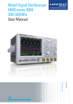
Benutzerhandbuch
Benutzerhandbuch/ /User
UserManual
Manual
DIGITAL Multimeter
HMC8012
User Manual
HMC8012 Brief Introduction
3 HMC8012 Brief
Introduction
The following chapter is an introduction to the most important HMC8012 multimeter features and settings allowing
you to use the measurement instrument promptly. A more
detailed description of basic operating steps is given in the
manual.
3.1 Setting Parameters
Each function and operating mode of the multimeter can
be selected with the keys on the front panel of the instrument. Use the respective function keys to select basic functions such as voltage, current or resistance measurement.
Advanced functions are managed by use of soft menu keys
to the right of the display. Pressing the SHIFT key activates
the numeric keypad.
3.2 Measuring a Direct/Alternating Voltage
An example for a basic measurement that can be performed with a multimeter is the measurement of a DC
voltage, for instance. The following measurement example
shows the individual steps to perform this measurement
effectively with the HMC8012. A DC power supply unit,
e.g. the HMP2030, is used.
To measure a DC voltage, you can connect a power supply
unit to the HMC8012 multimeter via silicon test leads, for
instance. Use the COM and V connectors on the bottom
right. Once the DC V key on the front panel of the instrument is used, the DC voltage value will be shown on the
multimeter display.
The measurement of alternating voltage applies the same
principle. In contrast to the DC voltage measurement, the
AC voltage measurement requires the use of the AC V key.
Please note that for an AC measurement, RMS values will
be shown on the display.
3.3 Automatic / Manual Selection of the Measurement Range
You can use the soft menu keys Range Up or Range Down
to switch the measurement range. Pressing Range Down
will switch to the next lower measurement range, pressing
Range Up will switch to the next higher measurement
range. The automatic selection of the measurement range
(Auto Range) is deactivated.
If the function Auto Range is activated, the measurement
instrument automatically selects the optimal measurement
range. If the selected measurement value is too great while
the manual selection of the measurement range is activated, the message OVER RANGE appears on the display.
3.4 Displaying Several Measurement Values
If you would like to view a second measurement value on
the display, select the soft menu 2nd Function and select
a second measurement value via knob. In the current example, the second measurement value could be AC V. The
second measurement value (2nd) will be displayed in blue
above the display of the main measurement value (Main). If
you select the option None via knob, the second measurement value will be deactivated.
3.5 Resistance Measurement with Zero Point
For the resistance measurement, connect measurement
cables with clamps to the respective connectors on the
front panel of the instrument. A two-wire measurement
only requires the COM and V connectors. A four-wire
measurement also requires the LO/HI connectors (SENSE).
After connecting the cables and connecting with a resistance, press the Ω key. The resistance value will show on
the display. During a resistance measurement, the cable
resistance (cable offset) requires particular attention. Especially for small resistances which may be close to the cable
offset it is recommended to zero the measurement section.
A zero measurement is also called a relative measurement,
i.e. each measurement value indicates the difference between a saved zero value and the input signal.
In this case it is necessary to short circuit the measurement
cables and then press the NULL key. This triggers the offset
correction of the entire measurement section. This value
will be shown on the display below the main measurement
value. The line resistance of the measurement cable, contact resistances and thermoelectric voltages between different metals have been intentionally eliminated by this offset
correction. The compensation values will not be stored
after the HMC8012 has been switched off and have to be
redetermined.
3.6 Statistic / Measuring Limits
In addition to the basic functions of the multimeter, mathematical functions are also available. These can be accessed by pressing the MEAS key on the front panel of the
instrument.
The soft menu Stats allows the user to activate individual
statistic functions (Min/Max, Mean, StdDev, Pk to Pk,
Count). Use the soft menu key STATS to activate (On) or
deactivate (Off) statistic values. The statistic functions will
be displayed below the main measurement value. You can
use the soft menu key #MEAS. to determine how many
measurement values are to be included in the statistic. You
can select the number of measurement values via knob
or via numeric keypad. If #MEAS is set to „0“, the statistic
will be performed on all measurement values. If #MEAS is
set to „7“, for instance, the statistic will be performed on 7
measurement values. The soft menu key Reset resets the
statistic.
35
HMC8012 Brief Introduction
The soft menu Limit allows you to select the High Limit
and Low Limit for a measurement. Based on these limits,
a test can be evaluated as passed or not passed. The
limits can be activated (On) or deactivated (Off) via soft
menu key LIMITS. The limits will be displayed below the
main measurement value. If a value is exceeded or falls
below the set limit during a test, it will be reflected by the
color display of the measurement value. A measurement
value that exceeds or falls below a limit is marked in red;
a measurement value within a limit is marked in green. In
addition, you can activate (On) or deactivate (Off) an error
tone (soft menu key Beeper) which will sound when the
value exceeds or falls below the set limits.
4 Setting Parameters
Each function and operating mode of the multimeter
can be selected with the keys on the front panel of the
instrument. Use the respective function key to select the
measurement function. An active measurement function is
highlighted by an illuminated white LED. Subsequent settings refer to the selected measurement function.
3.7 Storing Data
The HMC8012 multimeter can store two different types of
data:
❙❙ Instrument settings
❙❙ Screen displays
Out of these data types, screen displays can only be stored
on a USB stick. Instrument settings can be stored on a
USB stick or internally in the instrument to non-volatile
storage media.
Press the key SAVE/RECALL to open the store and load
menu. The soft menu Device Settings allows you to load
or store instrument settings. Select the submenu Save to
store the current instrument settings. Select the storage
location and the file name, then press the soft menu key
Save to save the current instrument settings. This file may
be reloaded at a later time.
The menu item Default Settings in the main menu also allows you to load the factory default settings.
Fig. 4.1: Numeric keypad and editing keys
4.1 Soft Menu Keys
The soft menu keys on the upper right of the screen allow
you to use the shown menu field in the display. Use the
numeric keypad or the knob to set the respective selected parameter. If a menu field has been selected via soft
menu keys, this function will be marked in yellow and will
be activated to set the parameter and function. If a specific setting makes an instrument setting unavailable, the
respective soft menu key will be deactivated and the label
will be displayed in gray.
4.2Numeric Keypad
The easiest way to enter a value precisely and promptly is
to use the numeric keypad. Pressing the SHIFT key activates the numeric keypad. When entering a numeric value
via keypad, you can accept the entry by pressing a soft
menu key with the corresponding unit. Before confirming
the parameter unit, you can delete any value that has been
entered incorrectly by pressing the key (SHIFT + SETUP
key). The ESC key allows you to cancel the operation to enter parameters. This will close the editing window.
4.3 Display of Measurement Values
The HMC8012 multimeter includes a brilliant TFT color
display with 5-3/4 digits. The display can show up to 3
measurement values simultaneously. The display of the
third measurement value is intended for the display of
mathematical functions, such as statistic or limit display.
The signal displays indicate the measurement units and the
operating environment of the multimeter. Figure 4.2 shows
an overview of the screen layout.
36
Description of the Operating Elements
ADC
Rate
Trigger
Local/ LogRemote ging
Interface
soft menu keys
Setting Parameters
If the function Auto Range is activated, the measurement
instrument automatically selects the optimal measurement
range. Activating the automatic mode enables you to
switch to a higher measurement range when 90% of the
respective range end value have been reached. Operation
will switch to the lower range if the value falls below 10%
of the range end value.
If the set measurement value is too large (whether the measurement range is selected manually or automatically), the display
shows the message OVER RANGE.
Display for math. function (e.g.: statistic)
Range (2nd)
Second measurement value
(2nd Function)
Range (Main)
Main measurement value
Zero measurement (Null)
Fig. 4.2: Screen layout
4.4 Displaying Several Measurement Values
The HMC8012 offers the option (depending on the selected
measurement function) to simultaneously show multiple
measurement values on the display. The main measurement value is labeled as „Main“. A second measurement
value can be activated via soft menu key 2nd Function
(depending on the measurement function). If you press the
soft menu key 2nd Function, you can use the soft menu
key SELECT and the knob to select a second measurement
value. The second measurement value (2nd) will be displayed in blue above the display of the main measurement
value (Main). If you select the option None via knob, the
second measurement value will be deactivated.
Main (main
measurement value)
DC V
AC V
DC I
AC I
DC V
−
●
●
−
2nd (secondary measurement value)
AC V DC I AC I
FredB
quency
●
−
−
−
●
−
−
●
−
−
●
−
−
●
−
●
●
●
●
●
dBm
●
●
●
●
Tab. 4.1: Displaying Several Measurement Values
4.5 Automatic / Manual Selection of the Measurement Range
Depending on the selected measurement value, you can
change the measurement range via soft menu keys Range
Up or Range Down. Pressing Range Down will switch to
the next lower measurement range, pressing Range Up
will switch to the next higher measurement range. This will
deactivate the automatic selection of the measurement
range (Auto Range).
Subject to change without notice
37
37
Instrument Functions
5Instrument
Functions
7
8
DC V
AC V
9
resistance of the measurement cable, contact resistances
and thermoelectric voltages between different metals have
been intentionally eliminated by this offset correction. The
compensation values will not be stored after the HMC8012
has been switched off and have to be redetermined. In
addition, you may also enter the NULL value numerically or
via knob.
SETUP
4
5
6
DC I
AC I
CAP
ESC
SAVE
RECALL
2
3
5.1 1Measuring
a DC
/ AC ENTER
Voltage
MEAS
HELP
SENSOR
A basic measurement that can be performed with a multi.
0
-meter
is the NULL
measurement
of aSHIFT
DC or an AC voltage.
TRIG
HOLD
CAT II
600 V
SENSE
4W
F10H250V
max. 200 Vpk
max.
Fused 10 A
max.
600 Vpk
max.
1000 Vpk
The maximum accuracy in measurements is achieved when using
the setting Slow (ADC Rate).
max. 1000 Vpk
-
+
voltage source
(AC/DC)
Fig. 5.1: Measuring a DC or AC voltage
To measure a DC or AC voltage, you can connect a voltage
source to the HMC8012 multimeter via silicon test leads,
for instance. Use the COM and V connectors on the bottom right. Once the DC V / AC V key on the front panel of
the instrument is used, the DC or AC voltage value will be
shown on the multimeter display.
Please note that for an AC measurement, RMS values will be
shown on the display.
In addition, it is possible to show a second function (2nd)
on the display. The soft menu key 2nd Function and the
knob allow you to select AC V, DC I, dB or dBm. The selected function is shown above the main measurement
value display. The menu display changes depending on the
selected second function. The soft menu key Remove 2nd
allows you to hide the second function from the display.
You can select the option Slow, Medium or Fast via soft
menu key AC Filter and knob. This applies to a low pass
filter. A lower setting (Slow) ensures more stable measurement values. However, the measurement is slow and signal
elements of higher frequency will be attenuated. Depending on the input frequency, this function will smoothen
the displayed value. The setting Medium is saved as default
value. Select the setting Slow for an input frequency of
<50kHz, and select Fast for a setting of >1kHz.
To compensate for the line resistance of measurement
cables, it is necessary to short circuit the measurement
cables and press the NULL key. This triggers the offset
correction of the entire measurement section. This value
will be shown next to the soft menu key NULL and on
the display below the main measurement value. The line
38
The soft menu key ADC Rate and the knob allow you to
set the display refresh rate to Slow (5 measurements per
second), Medium (10 measurements per second) or Fast
(200 measurements per second).
The function Auto Zero on page 2|2 of the DC V main
menu may be activated (ON) or deactivated (OFF). If this
function is activated, the instrument automatically compensates for the connected measurement cables and deducts
this offset from the measurement result (automatic zero
measurement).
The input impedance can be set via soft menu key Input
Imp. to 10 MOhm or >10 GOhm.
The impedance setting is dependent on the measurement range
If the second function (2nd Function) is activated (dB or
dBm), you have the option to define a reference value. For
the function dB, the reference value is the voltage (Ref.
Value). You can set the reference value numerically or via
knob. If a reference value is defined, you can reset the previously selected reference value via soft menu key Null.
For the function dBm, the reference value is 1mW and is
often used for RF signal measurements. If the dBm function is activated, the multimeter performs a measurement
and calculates the power supplied to a comparator resistance. The reference value (Ref. Value) in this case is 50,
75 or 600 Ω. In addition, you can set a user-defined value
(User) either numerically or via knob.
5.2 Measuring a DC / AC Current
To measure a DC or AC current, you can connect a power
supply unit to the HMC8012 multimeter via silicon test
leads, for instance. Use the COM and A connectors on
the bottom. Once the DC I / AC I key on the front panel of
the instrument is used, the DC or AC current value will be
shown on the multimeter display.
In addition, it is possible to show a second function (2nd)
on the display. The soft menu key 2nd Function and the
knob allow you to select AC I, DC V, dB or dBm. The selected function is shown above the main measurement
value display. The menu display changes depending on the
selected second function. The soft menu key Remove 2nd
allows you to hide the second function from the display.
To compensate for the line resistance of measurement
cables, it is necessary to short circuit the measurement
cables and press the NULL key. This triggers the offset
1
2
SENSOR
0
HOLD
.
NULL
3
ENTER
MEAS
HELP
-TRIG
SHIFT
8
AC V
F10H250V
max. 200 Vpk
max.
Fused 10 A
4
5
6
AC I
CAP
ESC
SAVE
RECALL
Instrument Functions
NULL
TRIG
SHIFT
max.
1000 Vpk
max. 1000 Vpk
CAT II
600 V
SENSE
4W
F10H250V
+
SETUP
DC I
HOLD
max.
600 Vpk
9
1
2
3
ENTER
5.3Measuring
Frequency
MEAS
HELP
SENSOR
The frequency display can be added
in the main function
.
0
-AC V and AC I as the second measurement function (2nd).
CAT II
600 V
SENSE
4W
7
DC V
max.
Fused 10 A
max. 200 Vpk
max.
600 Vpk
max.
1000 Vpk
max. 1000 Vpk
-
current source
(AC/DC)
+
Fig. 5.2: Measuring a DC or AC current
-
frequency source
correction of the entire measurement section. This value
will be shown next to the soft menu key NULL and on
the display below the main measurement value. The line
resistance of the measurement cable, contact resistances
and thermoelectric voltages between different metals have
been intentionally eliminated by this offset correction. The
compensation values will not be stored after the HMC8012
has been switched off and have to be redetermined. In
addition, you may also enter the NULL value numerically or
via knob.
The soft menu key ADC Rate and the knob allow you to set
the display refresh rate to Slow (5 measurements per second), Medium (10 measurements per second) or Fast (200
measurements per second).
The maximum accuracy in measurements is achieved when using
the setting „Slow (ADC Rate).
You can select the option Slow, Medium or Fast via soft
menu key AC Filter (main function AC I) and knob. This
applies to a low pass filter. A lower setting (Slow) ensures
more stable measurement values. However, the measurement is slow and signal elements of higher frequency will
be attenuated. Depending on the input frequency, this
function will smoothen the displayed value. The setting
Medium is saved as default value. Select the setting Slow
for an input frequency of <50 kHz, and select Fast for a setting of >1 kHz.
If the second function (2nd Function) is activated (dB or
dBm), you have the option to define a reference value. For
the function dB, the reference value is the current (Ref.
Value). You can set the reference value numerically or via
knob. If a reference value is defined, you can reset the previously selected reference value via soft menu key „Null.
For the function dBm, the reference value is 1mW and is
often used for RF signal measurements. If the dBm function is activated, the multimeter performs a measurement
and calculates the power supplied to a comparator resistance. The reference value (Ref. Value) in this case is 50,
75 or 600 Ω. In addition, you can set a user-defined value
(User) either numerically or via knob.
Fig. 5.3: Measuring frequency
The measurement time can be set via soft menu key Gate
Time. The measurement time can vary between 10ms,
100 ms and 1s and is shown below the frequency information on the display. The display refresh rate is dependent
on the selected ADC rate in the AC V or AC I mode. For
the setting Slow, the measurement rate of the frequency
measurement is 1 measurement per second, for Medium
it is 10 measurements per second and for Fast it is 100
measurements per second.
5.4 Measuring Resistance
For the resistance measurement, connect measurement
cables with clamps to the respective connectors on the
front panel of the instrument. A two-wire measurement
only requires the COM and V connectors. A four-wire
measurement also requires the LO/HI connectors (SENSE).
8
connecting with a resisAfter 7connecting
the 9cables and
SETUP
DC V
AC V
tance, press the Ω key. The resistance value will show on
ESC
4
5
6
the display.
During
aCAP
resistance
measurement, the cable
SAVE
AC I
DC I
RECALL
resistance
(cable
offset)
requires
particular attention. Espe1
2
3
ENTER
cially
for small resistances
which
MEAS
HELP may be close to the cable
SENSOR
offset0 it is recommended
to zero the measurement section.
.
-HOLD
NULL
TRIG
SHIFT
CAT II
600 V
SENSE
4W
F10H250V
max. 200 Vpk
max.
Fused 10 A
max.
600 Vpk
max.
1000 Vpk
max. 1000 Vpk
-
+
resistance 2-wire
(Ω)
Fig. 5.4: Measuring resistance (2-wire)
A zero measurement is also called a relative measurement,
i.e. each measurement value indicates the difference between a saved zero value and the input signal.
39
1
2
SENSOR
Instrument Functions
3
ENTER
1
MEAS
HELP
SENSOR
0
.
--
HOLD
NULL
TRIG
SHIFT
max. 200 Vpk
max.
Fused 10 A
max.
600 Vpk
ENTER
HELP
.
--
HOLD
NULL
TRIG
SHIFT
CAT II
600 V
SENSE
4W
max.
1000 Vpk
max. 1000 Vpk
-
3
MEAS
0
CAT II
600 V
SENSE
4W
F10H250V
2
F10H250V
max. 200 Vpk
max.
Fused 10 A
max.
600 Vpk
max.
1000 Vpk
max. 1000 Vpk
+
-
resistance 4-wire
(Ω)
+
capacity
Fig. 5.5: Measuring resistance (4-wire)
Fig. 5.6: Measuring the capacity
In this case it is necessary to short circuit the measurement
cables and then press the NULL key. This triggers the offset
correction of the entire measurement section. This value
will be shown on the display below the main measurement
value. The line resistance of the measurement cable, contact resistances and thermoelectric voltages between different metals have been intentionally eliminated by this offset
correction. The compensation values will not be stored
after the HMC8012 has been switched off and have to be
redetermined. In addition, you may also enter the NULL
value numerically or via knob.
and thermoelectric voltages between different metals have
been intentionally eliminated by this offset correction. The
compensation values will not be stored after the HMC8012
has been
switched
off
7
8
9 and have
to be redetermined. In
SETUPNULL value numerically or
DC V
V
addition,
youACmay
also enter the
ESC
4
5
6
via knob.
On page 2|2 of the Ω main menu, you can use the soft
menu key Mode to distinguish between 2-wire operation
(2w) and 4-wire operation (4w - (4w - connect SENSE
cables).
The soft menu key ADC Rate and the knob allow you to
set the display refresh rate for the 2-wire operation (2w) to
Slow (5 measurements per second), Medium (10 measurements per second) or „Fast (50 measurements per second).
For the 4-wire operation (4w), you can set the display refresh rate to Slow (5 measurements per second), Medium
(10 measurements per second) or Fast (25 measurements
per second).
The maximum accuracy in measurements is achieved when using
the setting „Slow (ADC Rate).
5.5 Measuring a Capacity
To measure a capacity, you can connect a capacitor with
the HMC8012 multimeter via silicon measurement cables
and clamp-type test probes, for instance. Use the COM
and V connectors on the bottom. Once the CAP key on the
front panel of the instrument is used, the capacity value
will be shown on the multimeter display.
To compensate for the line resistance of measurement
cables, it is necessary to short circuit the measurement
cables and press the NULL key. This triggers the offset
correction of the entire measurement section. This value
will be shown next to the soft menu key NULL and on
the display below the main measurement value. The line
resistance of the measurement cable, contact resistances
40
DC I
AC I
CAP
SAVE
RECALL
2
3
ENTER
5.6 1Measuring
Sensors
(PT100
/ PT500 / PT1000)
MEAS
HELP
SENSOR
Sensor measurements can be performed with various tem.
0
-perature
probes.
TheTRIG
temperature
probes HZ812 (2w) or
NULL
SHIFT
HOLD
CAT II
600 V
SENSE
4W
F10H250V
max. 200 Vpk
max.
Fused 10 A
max.
600 Vpk
max.
1000 Vpk
max. 1000 Vpk
-
+
temperature (2-wire)
Fig. 5.7: 2-wire sensor measurement (temperature)
HZ887 (4w) are available as optional accessories. Depending on the type used, you can select „2w“ or „4w“ with
the respective soft menu key. The soft menu key PT Type
allows you to select PT100, PT500 or PT1000 as probe
type. The measurement value may be displayed in °C, K or
°F (Unit).
To perform precise measurements, it is necessary to compensate for the measurement section with the NULL function, especially for the two-wire measurement. PT sensors
include a lead resistance which is typically indicated on
the data sheet. For an optimally adjusted measurement
section, it is necessary to know the exact lead resistance.
The measurement rate in this case is 10 measurements per
second.
5.7 Continuity / Diode Testing
opens the main menu for the diode
Pressing the key
and continuity testing If the soft menu key is marked in
1
2
SENSOR
3
ENTER
MEAS
HELP
0
.
--
HOLD
NULL
TRIG
Instrument Functions
SHIFT
CAT II
600 V
SENSE
4W
F10H250V
max. 200 Vpk
7
8
DC V
AC V
4
5
9
max.
Fused 10 A
SETUP
6
max.
600 Vpk
max.
1000 Vpk
max. 1000 Vpk
-
+
temperature (2-wire)
ESC
SAVE
Fig. 5.8:
sensor
measurement
(temperature)
I
CAP
DC I 4-wire AC
RECALL
1
2
3
ENTER
MEAS
SENSORthe respective
yellow,
functionHELP
„Diode or Continuity is
.
0
activated.
-HOLD
NULL
TRIG
SHIFT
CAT II
600 V
SENSE
4W
F10H250V
max. 200 Vpk
max.
Fused 10 A
The TRIG key will stop blinking. The label „Armed“ indicates that the instrument is waiting for a trigger (waiting for
the TRIG key to be pressed again) and is consequently not
triggering at the moment.
max.
600 Vpk
max.
1000 Vpk
max. 1000 Vpk
-
Diode
+
Fig. 5.9: Diode testing
For both functions, you can define / set a so-called threshold via soft menu key „Threshold. In addition, the soft
menu key Beep allows you to activate (On) or deactivate
(Off) an acoustic signal to be used in case of a threshold
violation. For the diode testing, the measurement rate is 10
measurements and for the continuity testing 200 measurements per second.
Single:
In the trigger mode Single, the soft menu key „Interval“
and the knob allow you to select a measurement interval.
The measurement interval describes the time between the
recorded measurements. For instance, if the function Interval is set to 2, all 2s will be included in the measurements.
In addition, the soft menu key Count and the knob enable
you to set the number of measurement values to be captured. Pressing the TRIG key starts the capture of measurement values. For instance, if you set an Interval of 2s and a
Count of 5, 5 measurement values will be captured in intervals of 2s. During the capture of the measurement values,
the LED for the TRIG key is blinking and the label „Trig“ is
displayed on the upper right of the screen. Alternatively, the
label „Armed“ indicates that the instrument is waiting for a
trigger (e.g. waiting for the TRIG key to be pressed again)
and is consequently not triggering at the moment.
Auto (Default Setting):
In the trigger mode Auto, the instrument does not wait for
a specific event. Instead, it performs permanent measurements. The number of measurements is dependent on the
selected ADC rate. In addition, you may define a threshold.
The measurement value display changes depending on
the selected treshold settings. If the function Continue is
activated, the display runs continuously. For the function
Above/Below Threshold a measurement value is not captured until the current value falls below or exceeds the set
treshold. If the instrument triggers permanently, the label
„Trig“ will be displayed on the upper right of the screen.
5.8 Measuring with HOLD Function
The HOLD function allows you to maintain the current
measurement results on the display. If you press the HOLD
key (white LED is illuminated), the measurement result(s)
will be frozen on the display. Press the HOLD key again
(LED is off) to deactivate the function.
5.9 Trigger Function
Pressing and holding the TRIG key or pressing the SETUP
key (submenu TRIGGER) opens the trigger menu. The
soft menu key Mode and the knob allow you to select the
respective trigger mode. There are three different options
to trigger a measurement:
Manual:
If the trigger mode „Manual“ is selected, press the key
TRIG to start recording measurement values. The TRIG key
blinks while measurement values are captured. Press the
TRIG key again to stop the capture of measurement values.
Fig. 5.10: Trigger menu Auto
Depending on which settings for the time interval and the number
of measurement values to be captured have been confirmed in the
trigger menu, these settings will be synchronized with the logging
menu (see chapter 6: Mathematical Functions).
41
Mathematical Functions
6Mathematical
Functions
In addition to the basic functions of the multimeter,
mathematical functions are also available.
These can be accessed by pressing the MEAS
key on the front panel of the instrument.
mits, a test can be evaluated as passed or not passed. The
limits can be activated (ON) or deactivated (OFF) via soft
menu key LimitS. The limits will be displayed below the
main measurement value (Main). If a value falls below or
exceeds the limits during a test, it will be reflected by the
color display of the measurement value. If the limits are observed, the measurement value is displayed in green. If the
value falls below or exceeds the set limits, the limit value
will be displayed in red. In addition, you can activate (ON)
or deactivate (OFF) an error tone (soft menu key Beeper)
which will sound when the value exceeds or falls below the
set limits.
Tab. 6.1 describes which mathematical functions can be
used with which measurement functions.
6.1Statistic
Measurement
function
DC V
AC V
DC I
AC I
Ω
CAP
SENSOR
Mathematic
functions
Stats
Limits
HOLD
NULL
●
●
●
●
●
●
●
●
●
●
●
●
●
−
●
●
●
●
●
●
●
●
●
●
●
●
●
●
−
−
−
−
Tab. 6.1: Measurement functions with possible math options
The soft menu Stats allows the user to activate the statistic
functions (Min/Max, Mean, StdDev, Pk to Pk, Count). Use
the soft menu key STATS to activate (On) or deactivate
(Off) statistic values. The statistic functions will be displayed below the main measurement value (Main). You can
use the soft menu key #MEAS. to determine how many
measurement values are to be included in the statistic. You
can select the number of measurement values via knob
or via numeric keypad (SHIFT key). The statistic may be
performed on a maximum of 50,000 measurement values.
If #MEAS is set to „0“, the statistic will be performed on all
measurement values. If #MEAS is set to „7“, for instance,
the statistic will be performed on 7 measurement values.
The soft menu key Reset resets the statistic. Additionally,
the soft menu AUTO REST is available. If the Auto Reset
function is activated (ON), the statistic measurement points
(Count) will be not reset in Auto Range mode.
6.3 Recording Data (Logging)
The soft menu Logging allows you to start the capture
of measurement values and to select various settings. Use
the soft menu key Logging to activate (ON) or deactivate
(Off) the capture and the storage of measurement values.
Use the soft menu Storage to select the storage location
(Internal/USB stick), the file name (File Name) and the file
format (CSV/TXT). The soft menu key Interval and the knob
allow you to select a measurement interval. The measurement interval describes the time between the recorded
measurements. For instance, if the function Interval is set
to 2, all 2s will be included in the measurements.
The soft menu Mode offers three different logging modes.
Select the function U if you intend to perform an infinite
data capture. The limiting factor in this context is the size
of the internal storage (maximum of 50,000 measurement
points) or of the connected USB stick. If the function N is
Depending on which settings for the time interval and the number
of measurement values to be captured have been confirmed in the
logging menu, these settings will be synchronized with the trigger
menu (see chapter 5: Instrument Functions).
activated, the soft menu key Count and the knob enable
you to set the number of measurement values to be captured. For instance, if you set an interval of 2 s and a count of
5, 5 measurement values will be captured in intervals of 2 s.
If the function T is activated, the soft menu key Time and
the knob enable you to set the duration of the capture of
the measurement values.
If the instrument shows OVER RANGE on the display, the statistic
measurement values can be not captured. This values will be displayed as Invalid Count in red.
6.2Measuring Limits (Limits)
The soft menu Limit allows you to select the High Limit
and Low Limit for a measurement. Based on these li42
Fig. 6.1: Logging menu setting
Documentation, Storage and Recall
Date Format Example for a Logging File
# HAMEG Device under test HM -Log-File ;
# Date: 2013-05-27 ;
# Start Time:, 14:27:07;
# Stop Time:, 14:27:11 ;
# Settings: ;
# ADC Rate : Slow;
# AC Filter : ------;
# Input Imp. : 10M;
;
;
;
DCV[V],ACV[V],Flag;
15.005159, 0.000186 ;
15.005088, 0.000195 ;
15.004896, 0.000200 ;
6.4 Power Display (Power)
The soft menu key Power activates the power display. The
function Power is only available if the measurement of DC /
AC current is activated. For instance, if you select the function DC V as the main measurement value (Main) and DC
I as secondary measurement value (2nd Function) (or vice
versa), the power will be shown in the lower display section
after confirming your selection via soft menu key Power.
If the power display is activated, the soft menu key Power
is marked in yellow. To deactivate the power display, press
the soft menu key Power again.
6.5 Measuring AC+DC (True RMS)
You can show the true RMS value (True RMS) below the
main measurement value (Main) on the display via soft
menu key AC+DC. This function is only available if the
measurement of AC voltage or AC current is activated.
Otherwise, the function is grayed out.
7Documentation,
Storage and
Recall
The multimeter HMC8012 enables users to store all screenshots and user settings. Instrument settings may be saved
internally. This data can also be stored on a connected USB
stick. Screenshots may only be stored on a USB stick. You
can access the main menu to store and load functions by
pressing the SAVE/RECALL key.
7.1 Instrument Settings
Use the soft menu Device Settings to save current instrument settings and to load previously saved settings.
Fig. 7.1: Menu for storing instrument settings
Press the soft menu key Save to open the „Save“ menu.
You can use the soft menu key Storage to select a possible
location (Internal or Front) where you would like to save
the instrument settings. Selecting the respective storage
location and confirming the selection via soft menu key Accept opens the file system manager. The FILE NAME can
be changed or adjusted to the corresponding setting (SET
is the default label). You can use the soft menu key Comment to enter a comment which will be displayed in the file
manager footer once a file has been selected. Instrument
settings are saved in the HDS format (binary). The format
may not be changed. The option Save allows you to store
the settings.
Instrument settings from a previous firmware version cannot be
loaded with a new firmware version.
To reload stored preference files, press the respective soft
menu key to open the soft menu Load. This open the file
manager where you can use the knob to select the respective file.
43
Documentation, Storage and Recall
Once the storage location and the respective settings file
has been selected, you can load the file by pressing the
soft menu key Load. To remove files that are no longer
required you can use the knob to select the respective settings file and remove it by pressing the soft menu key Remove File. If a USB stick is connected, you can also change
or delete directories.
The menu item Default Settings also allows you to load the
factory default settings.
7.2Screenshot
The most important format to store information for documentation purposes is the screenshot. A screenshot is an
image file which shows the current screen content at the
time that storage takes place.
Fig. 7.2: Screenshot menu
Screenshots may only be stored to a USB stick. If a USB
stick is connected, you can also change, create or delete
directories. Press Accept to confirm the location of the
target directory.
The FILE NAME can be changed or adjusted to the corresponding setting (SCR is the default label).
The file format of a graphics file determines the color depth
and the type of compression. The quality of the various
formats is identical for the multimeter graphics. You can
choose from the following file formats in the soft menu
Format:
❙❙ BMP = Windows Bitmap Format
❙❙ PNG = Portable Network Graphic
Use the soft menu key Color Mode and the knob to select
between Grayscale, Color and Inverted.
If Grayscale is selected, the colors are converted to gray
scales when the data is stored, if Color is selected, the data
is stored as it displays in the screen, and if Inverted
is activated, data will be stored in color with a white
back-ground.
If you press the key Save, the current screen will be saved
immediately to the selected storage location with the selected name and format.
44
The soft menu key Print allows you to print a screenshot
immediately to a connected printer (e.g. PCL or PCLX as
„printer language“). If a printer is detected, the soft menu
key Print will no longer be grayed out. The free software
HMScreenshot (software module of the HMExplorer software) enables the transfer of screenshots in bitmap or PNG
format from the HMC8012 via interface to a connected PC
where the screenshots may then be saved or printed. For
additional information on the software, refer to the internal
HMExplorer help at www.hameg.com.
Pressing and holding the HELP key allows you to save a screenshot to a connected USB stick.
General Instrument Settings
8 General Instrument Settings
Important general settings, such as basic settings or interface settings may be selected via SETUP key. Press the
key to move up one level.
8.1 Update (Instrument Firmware / Help)
Firmware and help (if available) are packed in one ZIP file.
Depending on the required extent of the update, the ZIP file
might include either all updates or simply the instrument
firmware, for instance. After downloading the ZIP file, unpack the data to the base directory of a USB stick. Then
connect the USB stick with the USB port of the multimeter
and press the SETUP key. Press the soft menu key Update
to access the update menu. Selecting this menu item
opens a window displaying version number, date and build
information of the currently installed firmware.
Pressing the soft menu key Firmware to update the instrument firmware will result in a search for the corresponding
file on the USB stick. The information for the new firmware
to be installed will then be displayed on the stick below the
row labeled NEW:. The version number will be displayed
in red in case the existing firmware on the instrument is
identical to the latest version; otherwise the version number will be shown in green. Only if this is the case, press
the soft menu Execute to start the update. To update the
help, select the menu item Help in the update menu. The
information window will now display all installed languages, the date and relevant information about the languages
available on the stick. The soft menu allows you to add,
remove or update languages. Please note the date format
(YYYY-MM-DD) in compliance with multilingual help ISO
8601 standards.
❙❙ Ethernet (IP address, sub-net mask etc.) and
❙❙ IEEE-488 GPIB interface (GPIB address)
Select the respective interface for the communication via
respective soft menu key. Set the required interface parameters via soft menu item Parameter. Please refer to chapter 9 „Remote Control via Interfaces“ for more information
about the used interfaces.
8.3 Trigger Settings
See chapter „Instrument Functions“ for a description of the
trigger menu.
8.4 Default Settings
The soft menu key „Default Settings“ allows you to load
the factory default settings.
8.5 General Settings (Misc)
Device Infos
This soft menu key allows you to retrieve instrument information such as serial number, software version etc.
Fig. 8.2: Device Infos
Date & Time
The soft menu key Date&Time allows you to set the time
and date and add a date and time stamp to printouts and
saved data records. The user can reset the date and time.
Date and time can be set via knob. The respective soft
menu item is activated when it is marked in yellow. Press
Save to accept the date and time parameters.
SOUND
The HMC8012 offers the option to issue a signal in the
event of an error (or simply as a control measure). This
signal can be activated (On) or deactivated (Off) via soft
menu key Error Beep or Control Beep.
Fig. 8.1: Firmware update menu
8.2 Interface Setting
The soft menu Interface enables you to select the settings
for:
❙❙ VCP (Virtual COM Port)
❙❙ USB
Display
The soft menu Display and the soft menu key Backlight
allows you to set the screen intensity via knob from 10% to
100%.
Key Brightness
The soft menu key „Key Bright“ allows you to set the key
brightness via knob from 0% to 100%.
45
General Instrument Settings
Device Name
In this menu, you can select an instrument name. Pressing
the soft menu key Device Name opens a keypad. Use the
knob to select the letters. You can confirm each letter via
ENTER key (SHIFT). Press the soft menu key Accept to
confirm the entered instrument name.
9 Remote Control
via Interfaces
As a standard feature, the HMC8012 is equipped with a
built-in interface card which includes an Ethernet and a
USB connection.
To enable communication, the selected interface and the respective settings in the instrument must be identical to the selections
for the PC.
9.2 USB
All currently available USB drivers have been fully tested and
released for Windows XP™, Windows VISTA™ and Windows 7™
(32 + 64 bit).
In addition to a LAN interface, the HMC8012 includes a
USB device port. For this interface, the user can select
if the instrument is accessed via virtual COM port (VCP)
or via USB TMC class. The traditional version of the VCP
allows the user to communicate with the HMC using any
terminal program via SCPI commands once the corresponding Windows drivers have been installed. These commands are generally compatible with the Agilent multimeters 34401A and 34410A. In addition, you may use the free
HAMEG software „HMExplorer“. This Windows application
offers HMC8012 instruments a terminal function, the option to create screenshots and to sort the measured data
storage.
A modern alternative to the virtual COM port (VCP) is the
control via USB TMC class. TMC stands for „Test & Measurement Class“ which indicates that the connected
measurement instrument can be recognized without
special Windows drivers if VISA drivers are installed and
that it can be used directly in corresponding environments.
The GPIB interface serves as model to the structure of the
TMC design. A major benefit of the USB TMC class is that
by sampling specific registers the user can determine if
commands have been terminated and if they have been
processed correctly. However, the communication via VCP
requires analysis and polling mechanisms within the controlling software which may significantly strain the interface
of the measurement instruments. The TMC status registers
solve this problem with the USB TMC in the same manner
as is the case with the GPIB interface for the hardware,
namely via corresponding control lines.
9.1 Ethernet
In addition to the USB interface, the interface card includes
an Ethernet interface. Select Ethernet as interface and
press the soft menu key Parameter to then determine the
settings for the necessary parameters directly within the
46
Remote Control via Interfaces
Configure the settings in the HMC8012 for all necessary
parameters after you select IEEE488 as interface and press
the soft menu key Parameter.
The optional IEEE 488 interface (GPIB) can only be factory-fitted
as it is necessary for this purpose to open the instrument and
break the guarantee seal.
Fig. 9.1: Ethernet-Settings
multimeter. You can specify all parameters and assign a
fixed IP address. You can also assign a dynamic IP address
with the activated DHCP function. Please contact your IT
management to configure the settings properly.
If DHCP is used and the system cannot assign an IP address to the
HMC8012 (for instance, if no Ethernet cable is connected or the
network does not support DHCP), it may take up to three minutes
until a timeout allows the interface to be configured again.
If the device has an IP address, it can be accessed via
web browser at this IP since the Ethernet interface includes an integrated web server. Enter the IP address in the
browser‘s address bar (http://xxx.xxx.xxx.xxx). This will
open a window including the instrument type and the serial
number.
Fig. 9.2: Web server
9.3 IEEE 488.2 / GPIB
In addition to the GPIB functions which are available via
USB TMC class, the HMC8012 is optionally available with
an integrated GPIB interface. This solution is particularly
attractive for customers who already have an existing GPIB
environment. With minimum efforts, an old instrument can
be replaced by a HMC8012 model.
47
Specifications
10 Specifications
Digital Multimeter HMC8012
All data valid at 23°C ±5K after 90 minutes warm-up and with 5 3/4 digits.
DC Specifications DC Accuracy in ± (% of reading + % of range):
Input Impedance
1 Year 23 °C ± 5 K
10 MΩ/>10 GΩ
10 MΩ/>10 GΩ
10 MΩ
10 MΩ
10 MΩ
0.015+0.002
0.015+0.002
0.020+0.002
0.020+0.002
0.025+0.002
Temp. Coefficient
0-18 °C, 28-55 °C
0.0010+0.0005
0.0008+0.0003
0.0010+0.0005
0.0015+0.0005
0.0015+0.0005
<0,30 V
<0,27 V
<0,2 V
<0,60 V
0.050+0.005
0.015+0.002
0.015+0.002
0.030+0.003
0.060+0.005
0,250+0.003
2.000+0.010
0.05+0.010
0.05+0.010
0,25+0.070
0,25+0.070
0.0020+0.0005
0.0020+0.0002
0.0020+0.0002
0.0020+0.0002
0.0020+0.0002
0.0080+0.0005
0,200+0.0005
0.008+0.0010
0.008+0.0010
0.012+0.0015
0.010+0.0010
4000 Ω
1 mA
0.05+0.010
0.005+0.0005
5 V
1 mA
0.05+0.010
0.005+0.0005
Function
Range1)
DC Voltage
400.000 mV
4.00000 V
40.0000 V
400.000 V
1000.00 V
Resistance
(2/4-wire) 2)
400.000 Ω
4.00000 kΩ
40.0000 kΩ
400.000 kΩ
4.00000 MΩ
40.0000 MΩ
250.000 MΩ
20.0000 mA
200.000 mA
2.00000 A
10.0000 A 3)
Continuity
Diode Test
DC Current 4)
Test Current
Voltage drop
1 mA
1 mA
100 µA
10 µA
1 µA
100 nA
460 nA || 10 MΩ (parallel)
Notes: 1
) 240.000 / 480.000 counts exept in 1000 V and 10 A range
2) Specifications are for 4-wire measurement; 2-wire measurement using NULL function.
3) Maximum current load at >5 A is 30 seconds, followed by a pause of >30 seconds
4) At 250 V maximum
AC Specifications AC Accuracy in ± (% of reading + % of range):
Function
Range1)
Frequency
1 Year 23 °C ± 5 K
Temp. Coefficient 0-18 °C, 28-55 °C
400.000 mV
10 Hz–20 Hz
3.0+0.05
0.01+0.01
4.00000 V
20 Hz–45 Hz
1.5+0.05
0.01+0.01
40.0000 V
45 Hz–20 kHz
0.3+0.05
0.01+0.01
400.000 V
20 kHz–50 kHz
1.0+0.05
0.02+0.01
750.00 V 6)
50 kHz–100 kHz
3.0+0.05
0.05+0.01
20.0000 mA
20 Hz–40 Hz
1.5+0.05
0.01+0.01
AC Current 5)
200.000 mA
40 Hz–1 kHz
0.5+0.05
0.01+0.01
2.00000 A
1 kHz–5 kHz
1.5+0.05
0.01+0.01
10.0000 A 4)
5 kHz–10 kHz 3)
2.5+0.05
0.01+0.01
Notes: 1) 240.000 / 480.000 counts exept in 750 V and 10 A range
2) Specifications are for sinusoidal curves. Input impedance is 1 MΩ parallel <100 pF
3) Except 10 A range
4) Maximum current load at >5 A is 30 seconds, followed by a pause of >30 seconds
5) At 250 V maximum
6) For ACV measurements and frequencies above 50 kHz the user is required to choose an appropriate measurement range
AC Voltage 2)
Frequency Counter Specifications Frequency Accuracy in ± (% of reading):
Function
Range1)
Frequency
1 Year 23 °C ± 5 K
Temp. Coefficient 0-18 °C, 28-55 °C
AC Voltage 2)
all ranges
5 Hz–700 kHz
0.01
0.005
20 mA, 200 mA
5 Hz–10 kHz
0.01
2 A, 10 A
5 Hz–5 kHz
0.01
Anmerkungen: 1) Display of frequency available as 2nd measurent for main functions ACV and ACI
2) Input sensitivity: >7,5 % of full scale (5 Hz-400 kHz) resp. >20 % (400-700 kHz)
AC
Current 2)
0.005
0.005
Frequency Counter Resolution
Setting
Measurement time
Display range
Slow
1 s
999,999 kHz
Resolution
1 Hz
Medium
100 ms
999,99 kHz
10 Hz
Fast
10 ms
999,9 kHz
100 Hz
Capacitance Specifications Capacitance Accuracy in ± (% of reading + % of range):
Function
Range
1 Year 23 °C ± 5 K
Temp. Coefficient 0-18 °C, 28-55 °C
Capacitance
5.000 nF
50.00 nF
500.0 nF
5.000 µF
50.00 µF
500.0 µF
2.0+2,5
1.0+2.0
1.0+0,5
1.0+0,5
1.0+0,5
2.0+1.0
0.02+0.002
0.02+0.002
0.02+0.002
0.02+0.002
0.02+0.002
0.02+0.002
48
Specifications
General Specifications
Data logging
Power supply:
Number of measuring
counts
Rate Log
Power consumption:
115 V / 230 V ±10%, adjustable voltage selector
on rear panel; Frequency 50Hz / 60Hz
25 W max., 12 W typ.
Ambient temperature:
0 …+55 °C (operating); –40 …+70 °C (storage)
EMC compliance:
DIN EN 61326-1, DIN EN 55011
Safety compliance:
Measuring Category:
DIN EN 61010-1, CAN/CSA-C22.2 No.
61010-1-12
CAT II, 600 V; CAT I, 1000 VDC, 750 VAC RMS
Dimensions:
222 x 88 x 280 mm
Weight:
approx. 2,7 kg
Warm-up time:
90 minutes
All data valid at 23°C ±5K after 90 minutes warm-up and with 5 3/4 digits
Duration Log
Log Daten
Interfaces
Internal: 50.000;
external: defined by USB stick capacity.
Min.: 5 ms typ. (in accordance to measuring
function and resolution); Max: 3.600 s
Internal: 250 s...50.000 h;
External: defined by USB stick capacity
Main, 2nd, Time-Stamp
USB 2.0 (TMC and CDC/VCP), Ethernet
10/100 (LXI in Preparation), IEEE-488/GPIB
optional
SCPI, compatible with Agilent 34401A and
34410A
Programming
Reading Rates
Slow
5 3/4
400.000
Reading
Rates
(per sec.)
5
Medium
4 3/4
40.000
10
Fast
4 3/4
40.000
200
Slow
5 3/4
400.000
5
Medium
4 3/4
40.000
10
Fast
4 3/4
40.000
200
Slow
5 3/4
200.000
5
Medium
4 3/4
20.000
10
Fast
4 3/4
20.000
200
Slow
5 3/4
200.000
5
1 MΩ parallel <100 pF (on all ranges)
Medium
4 3/4
20.000
10
Crest Faktor
Max. 10 (0,5% additional measurement
uncertainty)
Fast
4 3/4
20.000
200
CMRR
>60 dB 1 kΩ in the LO-line and frequency
<60 Hz
750 Vrms (for all ranges)
Additional Specifications
DC voltage
Measuring Method
Sigma Delta analog/digital converter
Input Resistance
>10 GΩ (selectable for ranges 400 mV / 4 V
10 MΩ (on all ranges)
120 dB for VCM <500 V, 1 kΩ unbalance in the
LO-line and 5 measurements/second
CMRR
SMRR
Input current
>60 dB for 50 or 60 Hz ±0,1% and 5
measurements/second
60 pA at 25 °C
Overload protection
1000 V for all ranges
Function
AC Voltage
DC Voltage
AC Current
AC voltage
Measuring Method
Input Resistance
Overload protection
AC coupled True RMS measurement
AC current / DC current
Shunt Resistance
13,75 Ω at 20 mA; 1,25 Ω at 200 mA; 25 mΩ bei
2 A, 10 A
Fuse: F10H250V on the front panel
DC Current
Setting
Resolution Display
Resistance
Slow
5 3/4
400.000
5
(2-wire)
Medium
4 3/4
40.000
10
Fast
4 3/4
40.000
50
Resistance
Slow
5 3/4
400.000
5
(4-wire)
Medium
4 3/4
40.000
10
Fast
4 3/4
40.000
25
Slow
6
999,999
1
Resistance
Medium
5
99,999
10
Measuring Method
Fast
4
9,999
100
Diode
4 3/4
40.000
10
Continuity
4 3/4
40.000
200
Temperature
4
999,9
10
Overload protection
Overload protection
Frequency
2-wire and 4-wire
1000 V for all ranges
Continuity
Measuring Method
1 mA constant current
Threshold value
Adjustable in 1Ω steps
Response Time
200 measurements/second
Overload protection
1000 V
Diode Test
Measuring Method
1 mA constant current
Threshold value
Adjustable in 10 mV steps
Response Time
10 measurements/second
Overload protection
1000 V
Temperature
Measuring Method
Sensor types
Resistance measurement with platinum
sensor
PT100, PT500, PT1000
Connection
2-wire, 4-wire
Overload protection
1000 V
Accessories supplied:
Line cord, printed operating manual, HZ15 Silicon test
lead with safety connector and test probe, 1m (black +
red), Software-CD
Math Functions
Statistics
Min/Max/Average/Standard deviation
Relative measurement
NULL key, offset via keyboard
Logarithmic functions
dB Reference level via keyboard or NULL key
dBm Reference impedance 50/75/600Ω or
freely selectable
Recommended accessories:
HZ812 PT100 Temperature probe 2-wire
HZ887 PT100 Temperature probe 4-wire
HZC95 19“ rackmount kit 2RU for HMC series
49
Appendix
11Appendix
11.1 List of Figures
Fig. 1.1: Operating positions. . . . . . . . . . . . . . . . . . . . . . 30
Fig. 1.2: Rear panel of the HMC with voltage selector and
connectors . . . . . . . . . . . . . . . . . . . . . . . . . . . . 32
Fig. 1.3: Connectors on the front panel of the
instrument. . . . . . . . . . . . . . . . . . . . . . . . . . . . . 32
Fig. 1.4: Product labeling in accordance with
EN 50419. . . . . . . . . . . . . . . . . . . . . . . . . . . . . . 33
Fig. 2.1: Front panel of the HMC 8012. . . . . . . . . . . . . . 34
Fig. 2.2: Rear panel of the HMC 8012 . . . . . . . . . . . . . . 34
Fig. 4.1: Numeric keypad and editing keys . . . . . . . . . . 36
Fig. 4.2: Screen layout . . . . . . . . . . . . . . . . . . . . . . . . . . 37
Tab. 4.1: Displaying Several Measurement Values. . . . . 37
Fig. 5.1: Measuring a DC or AC voltage. . . . . . . . . . . . . 38
Fig. 5.2: Measuring a DC or AC current. . . . . . . . . . . . . 39
Fig. 5.3: Measuring frequency. . . . . . . . . . . . . . . . . . . . 39
Fig. 5.4: Measuring resistance (2-wire) . . . . . . . . . . . . . 39
Fig. 5.5: Measuring resistance (4-wire) . . . . . . . . . . . . . 40
Fig. 5.6: Measuring the capacity . . . . . . . . . . . . . . . . . . 40
Fig. 5.7: 2-wire sensor measurement (temperature). . . 40
Fig. 5.8: 4-wire sensor measurement (temperature). . . 41
Fig. 5.9: Diode testing. . . . . . . . . . . . . . . . . . . . . . . . . . . 41
Fig. 5.10: Trigger menu Auto . . . . . . . . . . . . . . . . . . . . . . 41
Fig. 6.1: Logging menu setting. . . . . . . . . . . . . . . . . . . . 42
Fig. 7.1: Menu for storing instrument settings. . . . . . . . 43
Fig. 7.2: Screenshot menu. . . . . . . . . . . . . . . . . . . . . . . 44
Fig. 8.1: Firmware update menu . . . . . . . . . . . . . . . . . . 45
Fig. 8.2: Device Infos. . . . . . . . . . . . . . . . . . . . . . . . . . . . 45
Fig. 9.1: Ethernet-Settings . . . . . . . . . . . . . . . . . . . . . . . 47
Fig. 9.2: Web server . . . . . . . . . . . . . . . . . . . . . . . . . . . . 47
11.2Glossary
A
accuracy in measurements: 38, 39, 40
AC Filter: 38, 39, 43
AC voltage: 34, 35, 38, 43
ADC rate: 39, 41, 43
Alternating Voltage: 35
Auto Range: 35
B
Bitmap: 44
C
cable offset: 35, 39
capacity: 34, 40
continuity testing: 40, 41
D
DC voltage: 30, 34, 35
Diode Testing: 40
E
Ethernet: 46
50
F
file format: 42, 44
Firmware: 45
four-wire measurement: 35, 39
Frequency: 32, 39
frequency display: 39
G
GPIB: 47
GPIB address: 45
GPIB interface: 45
I
input frequency: 38, 39
instrument information: 45
instrument settings: 34, 36, 43
interface: 34, 44, 45, 46, 47
K
keypad: 34, 35, 36, 42, 46
knob: 34, 35, 36, 37, 38, 39, 40, 41, 42, 43, 44, 45, 46
L
limits: 32, 35, 36, 42
Logging: 42, 43
logging menu: 41, 42
M
main measurement value: 35, 36, 37, 38, 39, 40, 42, 43
Maintenance: 31
measurement categories: 32
measurement interval: 41, 42
measurement rate: 39, 40, 41
measurement time: 39
Measuring category: 32
O
OVER RANGE: 35, 37, 42
P
power display: 43
Product Disposal: 33
R
reference value: 38, 39
repair: 31
resistance: 31, 34, 35, 38, 39, 40
resistance measurement: 31, 35, 39
RMS: 35, 38, 43
RMS values: 35, 38
S
Safety: 30
safety class: 32
screen displays: 36
second measurement value: 35, 37
statistic: 34, 35, 36, 42
statistic functions: 35, 42
store: 36, 43, 44
Appendix
T
treshold settings: 41
trigger mode: 41
two-wire measurement: 35, 39, 40
U
USB: 34, 36, 42, 43, 44, 45, 46, 47
USB stick: 36, 42, 43, 44, 45
V
VCP: 45, 46
Virtual COM Port: 45
voltage value: 35, 38
W
Warranty: 31
Z
zero measurement: 35, 38, 39
Zero Point: 35
zero value: 35, 39
51
value-instruments.com
www.hameg.com
HAMEG Instruments GmbH
Industriestr. 6 | 63533 Mainhausen | Germany | Tel +49 (0) 6182 8000
R&S® ist ein eingetragenes Warenzeichen
der Rohde & Schwarz GmbH & Co. KG
HAMEG Instruments® ist ein eingetragenes Warenzeichen
der HAMEG Instruments GmbH
Markennamen sind Warenzeichen der Eigentümer
05 / 2014 | © HAMEG Instruments GmbH | 48-8012-C000
In Deutschland gedruckt | Änderungen vorbehalten