1
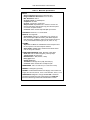
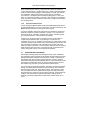
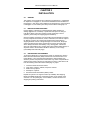
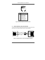
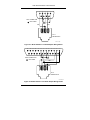
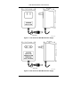
User’s Manual Model 241 Liquid Helium Level Monitor Lake Shore Cryotronics, Inc. 575 McCorkle Boulevard Westerville, Ohio 43082-8888 USA E-Mail Addresses: [email protected] [email protected] Visit Our Website: www.lakeshore.com Fax: (614) 891-1392 Telephone: (614) 891-2243 Methods and apparatus disclosed and described herein have been developed solely on company funds of Lake Shore Cryotronics, Inc. No government or other contractual support or relationship whatsoever has existed which in any way affects or mitigates proprietary rights of Lake Shore Cryotronics, Inc. in these developments. Methods and apparatus disclosed herein may be subject to U.S. Patents existing or applied for. Lake Shore Cryotronics, Inc. reserves the right to add, improve, modify, or withdraw functions, design modifications, or products at any time without notice. Lake Shore shall not be liable for errors contained herein or for incidental or consequential damages in connection with furnishing, performance, or use of this material. Rev. 1.2 P/N 119-025 26 June 2001 Lake Shore Model 241 User’s Manual LIMITED WARRANTY Lake Shore Cryotronics, Inc. (henceforth Lake Shore), the manufacturer, warrants this product for a period of 12 months from the date of shipment. During the warranty period, under authorized return of instruments or component parts to Lake Shore freight prepaid, the company will repair, or at its option replace, any part found to be defective in material or workmanship, without charge to the Owner for parts, service labor or associated customary shipping cost. Replacement or repaired parts will be warranted for only the unexpired portion of the original warranty. All products are thoroughly tested and calibrated to published specifications prior to shipment. Calibration Certifications are offered for 6 month periods only. Where such documentation must be updated, a re-certification service is offered by Lake Shore at a reasonable cost. LIMITATION OF WARRANTY This warranty is limited to Lake Shore products purchased and installed in the United States. This same protection will extend to any subsequent owner during the warranty period. It does not apply to damage caused by accident, misuse, fire, flood, or acts of God, from failure to properly install, operate, or maintain the product in accordance with the printed instructions provided. This warranty does not apply to defects resulting from improper or inadequate maintenance, unauthorized modification or misuse, operation outside of the environmental specifications for any product or part or buyer-supplied software interfacing. THIS WARRANTY IS IN LIEU OF ANY OTHER WARRANTIES, EXPRESSED OR IMPLIED, INCLUDING MERCHANTABILITY OR FITNESS FOR A PARTICULAR PURPOSE, WHICH ARE EXPRESSLY EXCLUDED. THE OWNER AGREES THAT LAKE SHORE’S LIABILITY WITH RESPECT TO THIS PRODUCT SHALL BE SET FORTH IN THIS WARRANTY, AND INCIDENTAL OR CONSEQUENTIAL DAMAGES ARE EXPRESSLY EXCLUDED. CERTIFICATION Lake Shore certifies that this product has been inspected and tested in accordance with its published specifications and that this product met its published specifications at the time of shipment. The accuracy and calibration of this product at the time of shipment are traceable to the United States National Institute of Standards and Technology (NIST); formerly known as the National Bureau of Standards (NBS), or to a recognized natural standard. TRADEMARK ACKNOWLEDGEMENT Manufacturers and sellers claim many designations as trademarks to distinguish their products. Where those designations appear in this manual and Lake Shore was aware of a trademark claim, the designations appear in initial capital letters with a ™ or ® symbol. Duo-Twist™, Quad-Lead™, and Quad-Twist™ are trademarks of Lake Shore Cryotronics, Inc. Cryo-Gloves® is a trademark of Tempshield. Copyright © 1994, 1997, 1999, and 2001 by Lake Shore Cryotronics, Inc. All rights reserved. No portion of this manual may be reproduced, stored in a retrieval system, or transmitted, in any form or by any means, electronic, mechanical, photocopying, recording, or otherwise, without the express written permission of Lake Shore. A Lake Shore Model 241 User’s Manual Declaration of Conformity We Lake Shore Cryotronics, Inc. 575 McCorkle Blvd. Westerville, OH 43082-8888 Hereby declare that the equipment specified conforms to the following Directives and Standards. Application of Council Directives: 89/336/EEC Standards to which Conformity is Declared: EN55022-A EN50082-1 Type of Equipment: Electronic Helium Level Meter Model Number: ___________________________ Signature 241 _____________________ Date John M. Swartz President B Lake Shore Model 241 User’s Manual This Page Intentionally Left Blank C Lake Shore Model 241 User’s Manual TABLE OF CONTENTS Chapter/Paragraph Title Page 1 INTRODUCTION ..........................................................................1-1 1.0 General.......................................................................1-1 1.1 Model 241 Level Monitor System Description ............1-1 1.2 Handling Liquid Helium and Liquid Nitrogen ..............1-5 1.2.1 Handling Cryogenic Storage Dewars ......................1-5 1.2.2 LHe and LN2 Safety Precautions ............................1-5 1.2.3 Recommended First Aid .........................................1-6 1.3 Electrostatic Discharge...............................................1-6 1.3.1 Identifying ESDS Components ...............................1-7 1.3.2 Handling ESDS Components..................................1-7 1.4 Safety Summary .........................................................1-7 1.5 Safety Symbols...........................................................1-8 2 INSTALLATION ...........................................................................2-1 2.0 General.......................................................................2-1 2.1 Inspection and Unpacking ..........................................2-1 2.2 Repackaging For Shipment ........................................2-1 2.3 Level Sensor Installation Recommendations .............2-2 2.4 Rear Panel Definitions................................................2-3 2.5 Initial Setup and Checkout Procedure ........................2-4 3 OPERATION ................................................................................3-1 3.0 General.......................................................................3-1 3.1 Front Panel Definitions ...............................................3-1 3.2 Alarm Setpoints ..........................................................3-2 3.3 Sample Period ............................................................3-3 3.4 Read ...........................................................................3-3 3.5 Units ...........................................................................3-3 3.6 Silence Alarm .............................................................3-3 3.7 Continuous Read........................................................3-4 4 REMOTE OPERATION ................................................................4-1 4.0 General.......................................................................4-1 4.1 Serial Interface ...........................................................4-1 4.1.1 Serial Interface Configuration .................................4-2 4.1.2 Baud Rate Settings .................................................4-2 4.1.3 Sample BASIC Serial Interface Program ................4-2 4.2 Serial Interface Command Summary .........................4-4 5 SERVICE ...................................................................................5-1 5.0 General.......................................................................5-1 5.1 General Troubleshooting ............................................5-1 Table of Contents i Lake Shore Model 241 User’s Manual TABLE OF CONTENTS (Continued) Chapter/Paragraph 5.2 5.3 5.4 5.4.1 5.4.2 5.5 5.6 5.7 6 Title Page Changing Power Setting & Fuse Replacement ..........5-1 Changing Audible Alarm & Baud Jumpers .................5-2 Calibration ..................................................................5-3 Resistance/Unit Length Known ...............................5-3 Resistance/Unit Length Unknown ...........................5-3 EEPROM Initialization ................................................5-5 Rear Panel Connector Definitions ..............................5-6 Serial Interface Cable and Adapters...........................5-7 OPTIONS, ACCESSORIES AND CABLES .................................6-1 6.0 General.......................................................................6-1 6.1 Options .......................................................................6-1 6.2 Accessories ................................................................6-1 APPENDIX A – SERIAL INTERFACE BASIC PROGRAM ................ A-1 APPENDIX B – GLOSSARY OF TERMINOLOGY ............................ B-1 LIST OF ILLUSTRATIONS Figure No. 1-1 2-1 3-1 4-1 5-1 5-2 5-3 5-4 5-5 5-6 5-7 5-8 6-1 6-2 6-3 6-4 6-5 Title Page Model 241 Level Monitor Front Panel....................................1-2 Model 241 Rear Panel...........................................................2-3 Model 241 Front Panel ..........................................................3-1 Serial Interface Connections .................................................4-1 Location of Fuse and Jumpers ..............................................5-2 Chart of NbTi Filament Resistance Values ...........................5-5 Sensor Input (DE-9) Connector Details.................................5-6 12 VDC Connector Details ....................................................5-6 Serial I/O (RJ-11) Connector Details.....................................5-7 Model 2001 RJ-11 Cable Assembly Wiring Details...............5-7 Model 2003 RJ-11 to DE-9 Adapter Wiring Details ...............5-8 Model 2002 RJ-11 to DB-25 Adapter Wiring Details .............5-8 120 Volt 60 Hz. Wall-Mount Power Supply ...........................6-2 220 Volt 50 Hz. Wall-Mount Power Supply ...........................6-2 Model 2001 RJ-11 Cable Assembly ......................................6-3 Model 2002 RJ-11 to DB-25 Adapter ....................................6-3 Model 2003 RJ-11 to DE-9 Adapter ......................................6-3 LIST OF TABLES Table No. 1-1 4-1 5-1 ii Title Page Model 241 Specifications ......................................................1-4 Serial Interface Specifications ...............................................4-2 Chart of NbTi Filament Resistance Values ...........................5-4 Table of Contents Lake Shore Model 241 User’s Manual CHAPTER 1 INTRODUCTION 1.0 GENERAL Lake Shore Cryotronics, Inc. designed and manufactures the Model 241 in the USA. This chapter provides a general description in Paragraph 1.1, handling liquid helium and nitrogen in Paragraph 1.2, electrostatic discharge in Paragraph 1.3, safety summary in Paragraph 1.4, and safety symbols in Paragraph 1.5. We welcome comments on this manual. Although we try to keep it errorfree, some may occur. To report an error, describe it briefly and include the appropriate paragraph, figure, table, or page number. Send comments to Lake Shore, Attn: Technical Publications, 575 McCorkle Blvd., Westerville, Ohio 43082-8888. This manual is subject to change without notice. 1.1 MODEL 241 LEVEL MONITOR SYSTEM DESCRIPTION Model 241 Liquid Helium Level Monitor features include: Level Measurement: • Type: NbTi Superconductive Wire. • Accuracy: Electronic – 1% of Active Sensor Length. Front Panel Display: 3½-Digit Custom LED with Annunciators. Other Major Operating Functions: • Adjustable Alarms. • English, Metric, or Percent Units. • Continuous, Timed, or One-Time Level Readings. • Adjustable Sample Periods. Computer Interface: Serial Interface (RS-232C Electrical Format). Sensor Compatibility: Various Length Sensors. The Model 241 Liquid Helium Level Monitor is a microcontroller-based instrument which measures the level of liquid helium using a hollow sensor with a superconductive Niobium-Titanium (NbTi) wire within it. The sensor, equipped with small liquid access holes, is placed in the cryogenic dewar. In normal operation, part of the sensor is in the liquid and part in the gas. A current passes through a 3 Ω heater at the top of the sensor that heats the wire and causes the wire in the gas to be non-superconducting. The current permits measurement of the wire resistance. The instrument reads the current with one set of leads, and the voltage with the other, for a four-wire resistance measurement. Introduction 1-1 Lake Shore Model 241 User’s Manual With the sensor vertically fixed in the dewar, and a known active sensor length, the instrument calculates sensor depth in the gas and converts it to the sensor depth in the liquid in inches, centimeters, or percent. To avoid liquid boil-off, current is applied to the superconductive wire for only 5 seconds when a reading is taken. A sensor not partially submersed in liquid helium within a vacuum overheats to destruction. To avoid this, the Model 241 reads the voltage across the sensor within 200 milliseconds after applying the current. If resistance is equal to or greater than resistance which implies a zero level (Maximum Resistance), the current turns off immediately and a zero level displays. The instrument produces a current of 70 mA in the superconductive wire and has a compliance of 30 volts. The maximum readable resistance is 428.6 Ω. The actual maximum is slightly less than 428.6 Ω because of lead and heater resistance. This corresponds to a maximum active sensor length of 104.5 cm (41.1 in.) for a superconductive wire of 4.1 Ω/cm (10.41 Ω/in.), or 79.4 cm (31.2 in.) for a superconductive wire of 5.4 Ω/cm (13.7 Ω/in.). If a sensor connection breaks, or the sensor wire opens, an alarm sounds, and the display shows error E27. Initiate sensor calibration from a recessed Cal key on the rear panel and control calibration inputs from the front panel. The enclosure need not be opened. The calibration constants store in EEPROM nonvolatile memory. To take a reading, press the front panel Read key. To take readings automatically at selected intervals, set the Sample Period with the front panel keys or send a command over the Computer Interface. Press the Continuous Read key to take readings at 1–2 second intervals. This is useful during a fill operation. P-241-1-1.bmp Figure 1-1. Model 241 Level Monitor Front Panel 1-2 Introduction Lake Shore Model 241 User’s Manual User-defined alarms indicate maximum level during a fill operation and minimum level during normal operation. A Serial I/O port provides a digital computer interface in RS-232C electrical format. An audible alarm alert users to a level below the Minimum Alarm Setpoint or, during the Continuous Read mode (as in a fill operation), to a level above the Maximum Alarm Setpoint. Alarm status can also be read over the Computer Interface. Enter and read Alarm Setpoints from the front panel or over the Computer Interface. The % reading references the Minimum Alarm Setpoint as 0% and the Maximum Alarm Setpoint as 100%. Level in % is given by: % Reading = 100 FG Reading − Min. AlarmSetpoint IJ H Max. Alarm Setpoint - Min. Alarm Setpoint K Thus, if the Maximum Alarm setpoint = 24 inches and the Minimum Alarm Setpoint = 12 inches, then a level of 12 inches = 0%, a level of 24 inches = 100%, and a level of 18 inches = 50%. If Maximum Alarm is disabled, then Active Probe Length substitutes for Maximum Alarm Setpoint in the equation. If Minimum Alarm is disabled, then zero substitutes for Minimum Alarm Setpoint in the equation. Introduction 1-3 Lake Shore Model 241 User’s Manual Table 1-1. Model 241 Specifications INPUT: Sensor Supported: NbTi Superconductive Wire. Range of Effective Resistance: 4.0 to 7.0 Ω/cm. Max. Resistance: 420 Ω. On-Time Current: 70 milliamperes. Compliance: 30 Volts. On-Time: 5 seconds or continuous. Sample Period: Adjustable from 1 minute to 19 hours 59 minutes and infinity (manual read only) from the front panel or over the computer interface. Connector: Rear mounted 9-pin DIN (DE-9) connector. ACCURACY: Electronic, 1% of Full Scale. DISPLAY: Five digit LED. Annunciators: Inches (in), centimeters (cm), percent (%), Max Alarm Setpoint (Max and Alarm), Min Alarm Setpoint (Min and Alarm). Calibration: active sensor length (Cal and in. or cm), and resistance/unit length (Cal, Ω, and in. or cm). ALARMS: Setpoints: Set Minimum and Maximum Alarm setpoints from the front panel or over the Computer Interface. Alarm Status: Audible Alarm. Read and clear alarm status over the Computer Interface. COMPUTER INTERFACE: Serial, RS-232C, Three Wire Baud rate: 1200 or 9600 changed by internal jumper Timing Format: Asynchronous Bits/Character: 1 Start, 8 Data, 1 Stop Parity Type: None Voltage levels: EIA Terminators: Carriage return (CR), line feed (LF) Connector: Rear mounted RJ-11 telephone jack DIMENSIONS: 136 x 72 x 166 mm (5.4 x 2.8 x 6.5 inches) WEIGHT: 0.9 kilogram (2 pounds) POWER: 12 VDC Wall Mounted Power Supply. Unit includes one supply: 90–125 VAC, 60 Hz., 0.5 A or 210–250 VAC, 50 Hz., 0.5 A. APPROVALS: Designed to comply with UL 1244 – Electrical and Electronic Measuring and Testing Equipment; VDE 0411 – Electronic Measuring Instruments and Automatic Controls 1-4 Introduction Lake Shore Model 241 User’s Manual 1.2 HANDLING LIQUID HELIUM AND LIQUID NITROGEN Helium and Nitrogen are colorless, odorless, and tasteless gases. They liquefy when properly cooled. Liquid Helium (LHe) and liquid nitrogen (LN2) may be used in conjunction with the Model 241. Although not explosive, there are certain safety considerations in the handling of LHe and LN2. 1.2.1 Handling Cryogenic Storage Dewars Operate all cryogenic containers (dewars) in accordance with manufacturer instructions. Safety instructions are normally posted on the side of each dewar. Keep cryogenic dewars in a well-ventilated place, protected from the weather, and away from heat sources. 1.2.2 LHe and LN2 Safety Precautions Transfer LHe and LN2 and operate storage dewar controls in accordance with manufacturer/supplier instructions. During transfer, follow all safety precautions written on the storage dewar and recommended by the manufacturer. WARNING: Liquid helium is a potential asphyxiant and can cause rapid suffocation without warning. Store and use in an adequately ventilated area. DO NOT vent the container in confined spaces. DO NOT enter confined spaces where gas may be present unless area is well-ventilated. If inhaled, remove to fresh air. If not breathing, give artificial respiration. If breathing is difficult, give oxygen. Get medical attention. WARNING: Liquid helium can cause severe frostbite to exposed body parts. DO NOT touch frosted pipes or valves. For frostbite, consult a physician immediately. If a physician is unavailable, warm the affected parts with water that is near body temperature. Two essential safety aspects of handling LHe are adequate ventilation and eye and skin protection. Although helium and nitrogen gases are non-toxic, they are dangerous because they replace air in a normal breathing atmosphere. Liquid helium is an even greater threat because a small amount of liquid evaporates to create a large amount of gas. Store and operate cryogenic dewars in open, well-ventilated areas. Introduction 1-5 Lake Shore Model 241 User’s Manual When transferring LHe and LN2, protect eyes and skin from accidental contact with liquid or the cold gas issuing from it. Protect eyes with full face shield or chemical splash goggles; safety glasses (even with side shields) are inadequate. Always wear special cryogenic gloves (Tempshield Cryo-Gloves® or equivalent) when handling anything that is, or may have been, in contact with the liquid or cold gas, or with cold pipes or equipment. Wear long sleeve shirts and cuffless trousers long enough to prevent liquid from entering shoes. 1.2.3 Recommended First Aid Post an appropriate Material Safety Data Sheet (MSDS) obtained from the manufacturer/distributor at every site that stores and uses LHe and LN2. The MSDS specifies symptoms of overexposure and first aid. If a person exhibits symptoms of asphyxia such as headache, drowsiness, dizziness, excitation, excessive salivation, vomiting, or unconsciousness, remove to fresh air. If breathing is difficult, give oxygen. If breathing stops, give artificial respiration. Call a physician immediately. If exposure to cryogenic liquids or cold gases occurs, restore tissue to normal body temperature (98.6 °F) by bathing it in warm water not exceeding 105 °F (40 °C). DO NOT rub the frozen part, either before or after rewarming. Protect the injured tissue from further damage and infection and call a physician immediately. Flush exposed eyes thoroughly with warm water for at least 15 minutes. In case of massive exposure, remove clothing while showering with warm water. The patient should not drink alcohol or smoke. Keep warm and rest. Call a physician immediately. 1.3 ELECTROSTATIC DISCHARGE Electrostatic Discharge (ESD) may damage electronic parts, assemblies, and equipment. ESD is a transfer of electrostatic charge between bodies at different electrostatic potentials caused by direct contact or induced by an electrostatic field. The low-energy source that most commonly destroys Electrostatic Discharge Sensitive (ESDS) devices is the human body, which generates and retains static electricity. Simply walking across a carpet in low humidity may generate up to 35,000 volts of static electricity. Current technology trends toward greater complexity, increased packaging density, and thinner dielectrics between active elements, which results in electronic devices with even more ESD sensitivity. Some electronic parts are more ESDS than others. ESD levels of only a few hundred volts may damage electronic components such as semiconductors, thick and thin film resistors, and piezoelectric crystals during testing, handling, repair, or assembly. Discharge voltages below 4,000 volts cannot be seen, felt, or heard. 1-6 Introduction Lake Shore Model 241 User’s Manual 1.3.1 Identifying ESDS Components Below are some industry symbols used to label components as ESDS: 1.3.2 Handling ESDS Components Observe all precautions necessary to prevent damage to ESDS components before installation. Bring the device and everything that contacts it to ground potential by providing a conductive surface and discharge paths. At a minimum, observe these precautions: 1. De-energize or disconnect all power and signal sources and loads used with unit. 2. Place unit on a grounded conductive work surface. 3. Ground technician through a conductive wrist strap (or other device) using 1 MΩ series resistor to protect operator. 4. Ground any tools, such as soldering equipment, that will contact unit. Contact with operator's hands provides a sufficient ground for tools that are otherwise electrically isolated. 5. Place ESDS devices and assemblies removed from a unit on a conductive work surface or in a conductive container. An operator inserting or removing a device or assembly from a container must maintain contact with a conductive portion of the container. Use only plastic bags approved for storage of ESD material. 6. Do not handle ESDS devices unnecessarily or remove from the packages until actually used or tested. 1.4 SAFETY SUMMARY Observe these general safety precautions during all phases of instrument operation, service, and repair. Failure to comply with these precautions or with specific warnings elsewhere in this manual violates safety standards of design, manufacture, and intended instrument use. Lake Shore Cryotronics, Inc. assumes no liability for Customer failure to comply with these requirements. Ground The Instrument To minimize shock hazard, connect instrument chassis and cabinet to an electrical ground. The instrument comes with a 3-conductor AC power cable. Plug it into an approved 3-contact electrical outlet or use a 3-contact adapter with the green ground wire firmly secured to an electrical ground (safety ground) at the power outlet. The power cable jack and mating plug meet Underwriters Laboratories (UL) and International Electrotechnical Commission (IEC) safety standards. Introduction 1-7 Lake Shore Model 241 User’s Manual Do Not Operate In An Explosive Atmosphere Do not operate the instrument in the presence of flammable gases or fumes. Operation of any electrical instrument in such an environment constitutes a definite safety hazard. Keep Away From Live Circuits Operating personnel must not remove instrument covers. Refer component replacement and internal adjustments to qualified maintenance personnel. Do not replace components with power cable connected. To avoid injuries, always disconnect power and discharge circuits before touching them. Do Not Substitute Parts Or Modify Instrument Do not install substitute parts or perform any unauthorized modification to the instrument. Return the instrument to an authorized Lake Shore Cryotronics, Inc. representative for service and repair to ensure that safety features are maintained. 1.5 1-8 SAFETY SYMBOLS Introduction Lake Shore Model 241 User’s Manual CHAPTER 2 INSTALLATION 2.0 GENERAL This chapter covers inspection and unpacking in Paragraph 2.1, repackaging for shipment in Paragraph 2.2, level sensor installation recommendations in Paragraph 2.3, rear panel control definitions in Paragraph 2.4, load connection in Paragraph 2.4, and initial system setup and checkout in Paragraph 2.5. 2.1 INSPECTION AND UNPACKING Inspect shipping containers for external damage. Make all claims for damage (apparent or concealed) or partial loss of shipment in writing to Lake Shore within 5 days from receipt of goods. If damage or loss is apparent, please notify the shipping agent immediately. Open the shipping containers. Use the packing list included with the system to verify receipt of the instrument, sensor, accessories, and manual. Inspect for damage. Inventory all components supplied before discarding any shipping materials. If there is freight damage to the instrument, file proper claims promptly with the carrier and insurance company and notify Lake Shore. Notify Lake Shore immediately of any missing parts. Lake Shore cannot be responsible for any missing parts unless notified within 60 days of shipment. Refer to the standard Lake Shore Warranty on the A Page (immediately behind the title page). 2.2 REPACKAGING FOR SHIPMENT To return the Model 241 or accessories for repair or replacement, obtain a Return Goods Authorization (RGA) number from Technical Service in the United States, or from the authorized sales/service representative from which the product was purchased. Instruments may not be accepted without a RGA number. When returning an instrument for service, Lake Shore must have the following information before attempting any repair. 1. 2. 3. 4. 5. Instrument model and serial number. User name, company, address, and phone number. Malfunction symptoms. Description of system. Returned Goods Authorization (RGA) number. Repack the system in its original container (if available). Affix shipping labels and FRAGILE warnings. Write RGA number on the outside of the container or on the packing slip. If not available, consult Lake Shore for shipping and packing instructions. Installation 2-1 Lake Shore Model 241 User’s Manual 2.3 LEVEL SENSOR INSTALLATION RECOMMENDATIONS The Lake Shore liquid helium (LHe) level sensor uses a small NiobiumTitanium (NbTi) wire as the detection element. A heater, located at the top of the sensor, creates and maintains a normal zone in the part of the wire above the LHe level while the part of the wire below the LHe remains superconducting. The output voltage of the sensor varies linearly with a change in liquid level. The Lake Shore Model 241 Level Monitor is calibrated for a specific level sensor. If sensors of different lengths are interchanged, the Model 241 requires recalibration. Since each installation is somewhat unique, general installation recommendations are as follows: 1. Carefully remove sensor from shipping tube and remove all packaging material. 2. The sensor heater is located at the top of the sensor. Mount sensor so that the electrical leads come out of the top. 3. Do not mount sensor inside a restricted area (inside another tube, etc.), where pressure differences in the gas may depress the liquid level around the sensor. Do not cover sensor liquid access holes. 4. Tape or clip the sensor to an appropriate support structure. To prevent damage, avoid applying excess pressure to the sensor tube. To allow for expansion and contraction of the sensor, avoid constraining both ends of the sensor. 5. To prevent cracking or breaking, avoid bending the sensor or lead wires when cold. 6. Do not operate sensor in a vacuum; it may thermally damage or destroy the superconducting wire. Do not inadvertently turn the Model 241 on with the sensor in an evacuated chamber. 7. Avoid installing in a location where icing (frozen water or gas) may occur. Ice formations may cause erratic operation. 8. Ensure the Model 241 is unplugged before connecting the sensor input connector. 9. For future reference, measure the active sensor length. It is the distance between the top and bottom bands on the sensor. There is about 0.5 inch inactive region at the sensor top and bottom. This dead zone is due to mounting considerations of the NbTi wire and cannot be avoided. The Lake Shore Level Sensor will provide years of accurate service and requires no maintenance if installed and operated in accordance with the instructions in this manual. The sensor is a sealed unit and internal repair is not practical. 2-2 Installation Lake Shore Model 241 User’s Manual 2.4 REAR PANEL DEFINITIONS P-241-2-1.bmp Figure 2-1. Model 241 Rear Panel The rear panel consists of the power on/off switch, power input connector, Serial I/O Connector, a DE-9 Sensor Input Connector, and the recessed Cal key. Rear panel connector pin-out details are provided in Chapter 5. Power On/Off Switch and 12V DC Power Input Connector. The line cord from the wall mounted power supply has a coaxial connector that plugs into the 12V DC Connector. The unit accepts either polarity. The Model 241 is Off when the lower portion of the power switch is depressed and On when the upper portion of the power switch is depressed. Connect both the Serial I/O and Sensor connectors prior to turning on power to the instrument. Serial I/O Connector. The Serial I/O (Input/Output) Connector accepts the standard RJ-11 telephone connector. Lake Shore offers RJ-11 to DE-9 or DB-25 adapters that permit connection to a customer-provided computer. Refer to Chapter 4 for details. Sensor Input Connector. A DE-9 connector is provided to plug in the sensor. Always turn off the instrument before connecting the sensor. Align the sensor connector with the rear panel connector and push straight in to avoid bent pins. For best results, secure the connector to the rear panel with the two thumbscrews. CAL Key. Newly installed units or sensors require calibration. Calibration requires two values: Active Sensor Length and Resistance per Unit Length. The recessed Cal button on the rear panel initiates calibration. The button is purposely recessed to avoid accidental calibration activation. The letters Cal display when in calibration mode. Refer to Paragraph 5.4 for further information. Installation 2-3 Lake Shore Model 241 User’s Manual 2.5 INITIAL SETUP AND CHECKOUT PROCEDURE This procedure verifies unit operation before taking measurements. 1. Ensure the power switch is in the OFF position. CAUTION: Check power source for proper voltage before connecting the line cord to the Model 241. Also check the plug in power supply for proper voltage input. 2. Check power source for proper voltage. The Model 241 requires a 12 VDC input. A single wall-mounted power supply is provided. The power supply is either 90–130 VAC, 60 Hz., 0.5 A, or 200–250 VAC, 50 Hz, 0.5 A. CAUTION: Connect level sensor to unit rear before applying power to the unit. Sensor damage may occur if connected with power on. 3. Install level sensor per recommendations in Paragraph 2.3. Route wiring to Model 241. 4. Plug DE-9 sensor connector into Sensor Input. Use thumbscrews to tighten connector to unit. If building a DE-9 cable, terminate the shield from the twisted pairs cable at the instrument on Pin 1 labeled Shield. Do not terminate the other end of the shield. 5. If applicable, ensure the Serial I/O rear panel connection is connected before applying power to the unit. 6. Plug coaxial connector to 12 VDC receptacle at rear of unit, then plug wall-mounted power supply into power connection. 7. Turn the power switch to the on position. The front panel display turns on. Once this abbreviated checkout procedure is successfully completed, the unit is ready for normal operation. 2-4 Installation Lake Shore Model 241 User’s Manual CHAPTER 3 OPERATION 3.0 GENERAL This chapter covers front panel definitions in Paragraph 3.1. Paragraphs 3.2 thru 3.7 describe the various front panel functions in detail. Refer to Chapter 4 for details on Serial Interface operation. 3.1 FRONT PANEL DEFINITIONS In normal operation, the 3½-digit LED provides current LHe level reading. Other information displays when using other functions on the keypad. See Figure 3-1. P-241-1-1.bmp Figure 3-1. Model 241 Front Panel Alarm Setpoints: Used in conjunction with the s and t keys to set minimum and maximum alarm setpoints. Refer to Paragraph 3.2. Sample Period: Used in conjunction with the s and t keys to specify time between level readings. Refer to Paragraph 3.3. Read: Initiates a one-time liquid level reading. Refer to Paragraph 3.4. Units: Toggles level units from cm, in., and %. Also cancels current function while retaining the previous settings. Refer to Paragraph 3.5. Silence Alarm: Silences the audible alarm. Refer to Paragraph 3.6. Continuous Read: Initiate a continuous read. Refer to Paragraph 3.7. s: Increments a numerical display. Press and hold for rapid scrolling. t: Decrements a numerical display. Press and hold for rapid scrolling. Operation 3-1 Lake Shore Model 241 User’s Manual 3.2 ALARM SETPOINTS The Alarm Setpoints key displays or modifies the minimum and maximum alarm setpoints. To display current alarm setpoints: 1. Push Alarm Setpoints. The first display is the low alarm setpoint. The Alarm and Min annunciators display with the minimum alarm setpoint in inches (in) or centimeters (cm). 2. Push Alarm Setpoints again. The second display is the high alarm setpoint. The Alarm and Max annunciators display with the maximum alarm setpoint in inches (in) or centimeters (cm). 3. Push either Alarm Setpoints or Units to escape. To modify the alarm setpoints: 1. Push Alarm Setpoints. The first display is the low alarm setpoint. The Alarm and Min annunciators display with the minimum alarm setpoint in inches (in) or centimeters (cm). NOTE: Press and hold the s or t keys to rapidly increment or decrement the numerical value. The rapid number cycling occurs at two rates; medium and fast. The first five numbers advance at the medium rate. The remaining numbers advance at the fast rate until the key is released or reaches the end of possible values. 2. Use the s and t keys to increment or decrement the value. Below zero the display shows five dashes (- - - - -). Dashes mean the minimum alarm is disabled. 3. When the desired minimum alarm setpoint is reached, push Alarm Setpoints and proceed to Step 4. To retain the previous minimum alarm setpoint, press Units to escape. 4. The Alarm and Max annunciators display with the maximum alarm setpoint in inches (in) or centimeters (cm). 5. Use the s and t keys to increment or decrement the value. Below zero the display shows five dashes (- - - - -). Dashes mean the maximum alarm is disabled. NOTE: Set the maximum alarm setpoint no higher than the maximum active sensor length. 6. To accept the new Max alarm setpoint, push Alarm Setpoints. To retain the existing Max alarm setpoint and escape to the normal level display, press Units. During normal operation, the alarm sounds only for a reading below the minimum alarm point. The maximum alarm point sounds only while the Model 241 is in Continuous Read mode. 3-2 Operation Lake Shore Model 241 User’s Manual 3.3 SAMPLE PERIOD Displays the Sample Period in hours and minutes. Set the sample period from 0 to 19 hours 59 minutes. Below 0–00 and above 19–59, a series of five dashes (- - - - -) turns the sample period off. When dashes are selected, no readings are taken unless the Read or Continuous Read key is pushed or a request is made via the Serial Interface. After pushing the Sample Period key, use the s and t keys to increment or decrement the sample period. To accept the new duration time, push Sample Period again. To retain the previous sample period and escape to the normal helium level display, press Units. 3.4 READ Push the Read key to initiate a level reading. During a reading, a series of ascending dashes appear on the left side of the display. A single reading takes about 5 seconds. NOTE: Pushing any key while a reading is taken aborts the reading. A new reading begins automatically. 3.5 UNITS The Units key cycles the level units between centimeters (cm), inches (in), and percent (%). The display immediately changes to the new units. Units also escapes the current function while retaining the previous settings. 3.6 SILENCE ALARM When the audible alarm sounds, press Silence Alarm to turn it off. The word OFF displays for 1 second, then the normal helium level display returns. The audible alarm is disabled for 30 minutes. If Silence Alarm is pressed again, the word ON displays for 1 second and then returns to the normal helium level display. This enables the audible alarm. The audible alarm can be toggled between ON and OFF. Toggle it OFF to disable the audible alarm for 30 minutes. After 30 minutes, the word ON displays, the audible alarm is enabled, and a reading is taken. If Silence Alarm is held down while the instrument is turned on, the instrument initializes the EEPROM. The instrument may require recalibration after EEPROM initialization. Refer to Paragraph 5.5 for details. To disable the audible alarm, set the jumper inside the unit. Refer to Paragraph 5.3 for further information. Operation 3-3 Lake Shore Model 241 User’s Manual 3.7 CONTINUOUS READ Push Continuous Read to place the Model 241 in a mode where the current is on continuously. The first reading is taken at 5 seconds. After that, readings are taken every 1–2 seconds. If the Model 241 detects a resistance greater than the maximum probe resistance, it turns off the current. After a delay of 5 seconds, it attempts another reading. Continuous read is independent of the Sample Period setting. Push Continuous Read or Read to return to the normal helium level display. The Maximum Alarm is active only if Continuous Mode is enabled (i.e., set to any value other than all dashes (- - - - -). NOTE: Pushing any key while a reading is taken aborts the reading. Continuous mode continues after the interrupt is complete, except for pushing the Continuous Read or Read key, which returns the unit to the normal helium level display. 3-4 Operation Lake Shore Model 241 User’s Manual CHAPTER 4 REMOTE OPERATION 4.0 GENERAL This chapter covers the built-in Serial Interface in Paragraph 4.1 and corresponding commands in Paragraph 4.2. 4.1 SERIAL INTERFACE The Model 241 has a Serial I/O Interface in RS-232C electrical format. RS-232C is a standard of the Electronics Industries Association (EIA) describing one of the most common interfaces between a computer and electronic equipment. This interface requires a customer-supplied computer equipped with a Serial Interface port. The Serial Interface connection between the computer and the Model 241 permits remote monitoring and control of the Model 241 control functions, which in turn controls the operation of the Model 241. See Figure 4-1. The Serial Interface can both transmit and receive information. In transmission (Tx) mode, the interface converts parallel information to serial information and sends it over a cable up to 50 feet long (or longer with proper shielding). In the receiving (Rx) mode, the interface converts the serial information back to parallel information for processing. This section describes the Serial Interface hardware configuration in Paragraph 4.1.1, Serial Interface settings in Paragraph 4.1.2, and a sample BASIC program to establish communications between the computer and the Model 241 in Paragraph 4.1.3. The Serial Interface commands are provided in Paragraph 4.2. Model 241 Rear View 12 VDC On Serial I/O Probe Input Shield Cal Off I+ V+ V- I- Customer-Supplied Computer C-241-4-1.eps Figure 4-1. Serial Interface Connections Remote Operation 4-1 Lake Shore Model 241 User’s Manual 4.1.1 Serial Interface Configuration The following is a description of the Serial Interface. Communication parameters are defined in Table 4-1. Terminators are fixed to carriage return (CR) and Line Feed (LF). Add query to the end of a command string if the instrument must return information. For example, UNITS IN commands the Model 241 to set the level units to inches (IN). Add the command UNITS? to confirm the change. The Serial Interface connector is a standard 6-wire RJ-11 telephone jack. Lake Shore offers the Model 2001 10-foot Cable Assembly, Model 2002 RJ-11 to DB-25 Adapter, and the Model 2003 RJ-11 to DE-9 Adapter. Refer to Chapter 6 for further details. Table 4-1. Serial Interface Specifications Transmission: Three-Wire Baud Rate: 1200 or 9600 Connector: RJ-11 Modular Socket Bits per Character: 1 Start, 8 Data, 1 Stop Timing Format: Asynchronous Parity Type: None Transmission Mode: Half Duplex Terminator: LF (0AH), CR (0DH) Data Interface Levels: Transmits/Receives Using EIA Voltage Levels 4.1.2 Baud Rate Settings Changing the Baud rate involves opening the unit and repositioning a jumper. The Baud rate is set to 9600 at the factory. Refer to Paragraph 5.3 for instruction on changing the Baud rate. 4.1.3 Sample BASIC Serial Interface Program Below is a sample Model 241 serial poll routine written in Quick BASIC. Refer to Appendix A for a larger, more interactive program. 'INTERACTIVE SERIAL POLL ROUTINE FOR 241 'WRITTEN FOR QUICK BASIC CLS 'OPEN STATEMENT FOR 300 BAUD OPEN “COM1:300,N,8,1,RS” FOR RANDOM AS #1 L1: L2: 4-2 INPUT “ENTER COMMAND”;A$ 'ENTER COMMAND STRING FROM KB PRINT #1,A$ 'SEND STRING TO 241 IF MID$(A$,LEN(A$),1) <> “?” THEN GO TO L2 'TEST QUERY SENT LINE INPUT #1,B$ 'INPUT RESPONSE ONLY IF QUERY INPUT$(1,1) 'GET LINE FEED PRINT B$ 'OUTPUT TO SCREEN PRINT GO TO L1 'GET NEXT COMMAND STRING END Remote Operation Lake Shore Model 241 User’s Manual Below are examples using the above BASIC program. (Information returned by the computer appears against the left column. Input provided by the user appears in bold type.) ENTER COMMAND? LEVEL? 24.5 ENTER COMMAND? UNITS? E ENTER COMMAND? OHM 13.7 ENTER COMMAND? OHM? Helium Level Query. Unit returns the last reading. Units Query. Instrument will return current units. Resistance/Unit set to 13.7 Ω/in. Resistance/Unit Query. Returns the 13.7 Ω/in. setting. 13.7 ENTER COMMAND? Additional notes on the serial interface commands are as follows: • Queries have the same syntax as the associated setting command followed by a question mark (?). They should return the same information that is sent. • Leading zeros and zeros following a decimal point are not needed in a command string. • Correctly spelled commands without a “?” are ignored. Incorrectly spelled commands are also ignored. • Blank spaces are ignored by the program. • A leading negative sign only occurs from a LEVEL? query where the units are in % and the level is below the minimum alarm setpoint. Remote Operation 4-3 Lake Shore Model 241 User’s Manual 4.2 MODEL 241 SERIAL INTERFACE COMMAND SUMMARY Command QRST QIDN? LEVEL LEVEL? LEVS? UNITS UNITS? MAXA MAXA? MAXS MAXS? MINA MINA? MINS MINS? PERIOD PERIOD? LENGTH LENGTH? OHM/L OHM/L? Function Page Reset ..........................................................................4-5 Identification Query.....................................................4-5 Liquid Level ................................................................4-5 Liquid Level Query......................................................4-5 Level Status Query .....................................................4-5 Level Units ..................................................................4-5 Level Units Query .......................................................4-6 Maximum Alarm Setpoint............................................4-6 Maximum Alarm Setpoint Query.................................4-6 Maximum Alarm On/Off ..............................................4-6 Maximum Alarm On/Off Query....................................4-6 Minimum Alarm Setpoint.............................................4-7 Minimum Alarm Setpoint Query..................................4-7 Minimum Alarm On/Off ...............................................4-7 Minimum Alarm On/Off Query ....................................4-7 Sample Period ............................................................4-8 Sample Period Query .................................................4-8 Sensor Active Length .................................................4-8 Sensor Active Length Query.......................................4-8 Sensor Resistance per Unit Length............................4-8 Sensor Resistance per Unit Length Query .................4-8 An explanation of the command structure appears below. Brief Description of Function Command Name Syntax of user input. Information returned in response to query. Explanation of returned data. 4-4 UNITS? Level Data Reading Query Input: UNITS? Returned: IN, CM, or % Remarks: Returns the level units where IN = Inches, CM = centimeters, or % = Percent. Remote Operation Lake Shore Model 241 User’s Manual QRST Reset Command QRST? Input: Returned: Nothing Remarks: Similar to turning the power off and back on again. QIDN? Identification Query Input: Returned: Remarks: Example: QIDN? Manufacturer, model number, software date Identifies the instrument model and software level. LSCI,MODEL241,10/01/92[term] LEVEL Initiate Liquid Level Reading LEVEL Input: Returned: Nothing Remarks: Requires about 5 seconds to take reading. If Model 241 is in Continuous mode, this command returns the instrument to the normal mode of reading according to the Sample Period setting. LEVEL? Current Liquid Level LEVEL? Input: Returned: ±XXX.X Remarks: Returns latest level reading value: four numbers with appropriate decimal point. Requires UNITS? command to define reading. Unit returns error message E27 if current reading is low, i.e., sensor leads may be open. LEVS? Level Status LEVS? Input: Returned: 0 or 1 Remarks: 1 = new reading available; 0 = LEVEL or LEVS already queried since last reading. UNITS Set Level Units Status UNITS IN, UNITS CM, or UNITS % Input: Returned: Nothing Remarks: Programs level units: IN = Inches, CM = centimeters, % = percent. Remote Operation 4-5 Lake Shore Model 241 User’s Manual UNITS? Level Units Query UNITS? Input: Returned: IN, CM, or % Remarks: Returns the level units: IN = inches, CM = centimeters, % = percent. MAXA Set Maximum Level Alarm Setpoint MAXA XX.X Input: Returned: Nothing Remarks: Programs the Maximum Level Alarm Setpoint where XX.X = 0 to 99.9. Sending all dashes (- - - - -), one dash ( – ), or the MAXS 0 command disables the Maximum Level Alarm. MAXA? Maximum Level Alarm Query MAXA? Input: Returned: XX.XIN or XX.XCM Remarks: Returns the Maximum Level Alarm Setpoint where XX.X = 0 to 99.9. IN = inches, CM = centimeters. All dashes (- - - - -) indicates a disabled Maximum Level Alarm. MAXS Set Maximum Level Alarm Enable MAXS 0 or MAXS 1 Input: Returned: Nothing Remarks: When set to 0, the Maximum Alarm Enable bit is cleared, no alarm sounds, and the front panel displays dashes (- - - - -). When set to 1 and unit is in Continuous Read mode, the Maximum Alarm Enable bit is set (1) and a Maximum Alarm sounds if level is above Maximum Alarm Setpoint. MAXS? Maximum Level Alarm Enable Query MAXS? Input: Returned: 0 or 1 Remarks: 0 = off (level is below Maximum Alarm Setpoint); 1 = on (level is above Maximum Alarm Setpoint when in the Continuous Read mode). A 1 cannot be returned if the Maximum Alarm was not enabled. Enable Maximum Alarm with the MAXS1 command. A 1 returned with the MAXS? Command means that the level has been above the Maximum Alarm Setpoint since the Maximum Alarm was last enabled. 4-6 Remote Operation Lake Shore Model 241 User’s Manual MINA Set Minimum Level Alarm Setpoint MINA XX.X Input: Returned: Nothing Remarks: Programs the Minimum Level Alarm Setpoint where XX.X = 0 to 99.9. Sending all dashes (- - - - -), one dash ( – ), or the MINS 0 command disables the Minimum Alarm. Examples: MINA 100, MINA – MINA? Minimum Level Alarm Query MINA? Input: Returned: XX.XIN or XX.XCM Remarks: Returns the Minimum Level Alarm Setpoint where XX.X = 0 to 99.9, IN = inches, CM = centimeters. All dashes (- - - - -) indicates the Minimum Level Alarm is disabled. MINS Set Minimum Level Alarm Enable MINS 0 or MINS 1 Input: Returned: Nothing Remarks: When enable = 0, the Minimum Alarm Enable bit in the instrument is cleared, no alarm sounds, and the front panel displays dashes (- - - - -). When enable = 1, the Minimum Alarm Enable bit is set (1) and a Minimum Alarm sounds if the level is below the Minimum Alarm Setpoint. MINS? Minimum Level Alarm Enable Status Query MINS? Input: Returned: 0 or 1 Remarks: 0 = off (the level has been below the Minimum Alarm Setpoint since the Minimum Alarm was last enabled). 1 = on (the level has been above the Minimum Alarm Setpoint since last enabled). A 1 cannot be returned if the Minimum Alarm was not enabled. Enable the Minimum Alarm with the MINS1 command. A 1 returned with the MINS? means that the level has been below the Minimum Alarm Setpoint since the Minimum Alarm was last enabled. Remote Operation 4-7 Lake Shore Model 241 User’s Manual PERIOD Set Sample Period Setpoint PERIOD HH-MM Input: Returned: Nothing Remarks: Sets the Sample Period: HH = hours from 0 to 19, MM = minutes from 0 to 59. Sending all dashes (- - - - -), or simply one dash ( – ), implies infinite Sample Period. Examples: PERIOD 00-01 = 1 minute PERIOD 01-00 = 1 hour PERIOD ----- = Infinite (Off) PERIOD? Sample Period Setpoint Query PERIOD? Input: Returned: HH-MM Remarks: Queries the Sample Period: HH = hours from 0 to 19, MM = minutes from 00 to 59. All dashes (- - - - -) = an infinite Sample Period. LENGTH Set Active Sensor Length Input: Returned: Remarks: Example: LENGTH XX.X Nothing XX.X = Active Sensor Length in current units. LENGTH 24.5 LENGTH? Active Sensor Length Query LENGTH? Input: Returned: XX.XIN or XX.XCM Remarks: XX.X = length, IN = inches, CM = centimeters. OHM/L Set Resistance Per Unit Length OHM/L XX.XX Input: Returned: Nothing Remarks: Sets Resistance/unit length. Length units are the same as the Active Sensor Length units (inches or centimeters). Example: OHM/L 11.56 OHM/L? Resistance Per Unit Length Query OHM/L? Input: Returned: XX.XX Remarks: Returns Resistance/unit length. Length units are the same as the Active Sensor Length units (inches or centimeters). 4-8 Remote Operation Lake Shore Model 241 User’s Manual CHAPTER 5 SERVICE 5.0 GENERAL This chapter covers general troubleshooting in Paragraph 5.1, changing power settings and fuse replacement in Paragraph 5.2, changing Baud rate and audible alarm jumpers in Paragraphs 5.3, calibration in Paragraph 5.4, EEPROM initialization in Paragraph 5.5, rear panel connector definitions in Paragraph 5.6, and Serial Interface cables and adapters in Paragraph 5.7. 5.1 GENERAL TROUBLESHOOTING If there is no power, verify outlet power and secure power cord connection at the unit rear. To check the fuse, open unit, remove fuse, and test fuse with ohmmeter. Do not rely on visual inspection of fuse. See Figure 5-1. Fuse rating is 1.0 A. If the display is lit but not responding, hold the Silence Alarm key while turning the Model 241 on. This initializes the internal EEPROM. The instrument may require recalibration after EEPROM initialization. Setpoints must then be reentered. Error message E27 displayed or returned with the RS-232 command LEVEL? indicates a low current reading, which means possible open sensor leads. 5.2 CHANGING POWER SETTING AND FUSE REPLACEMENT Changing from 110 to 220 Volt operation is accomplished by changing the external power supply. No other adjustments to the Model 241 are required when changing voltage. Use the following procedure to replace the fuse. WARNING: To avoid potentially lethal shocks, turn off instrument and disconnect it from the AC power line before performing this procedure. 1. Turn off unit. 2. Unplug 12 V line from external power supply. 3. Open unit. 5. Remove existing fuse. Replace with 1 A fuse. 6. Reassemble unit. 7. Plug line cord into rear of unit. 8. Perform initial setup and checkout procedure in Paragraph 2.5. Service 5-1 Lake Shore Model 241 User’s Manual P-241-5-1.bmp Figure 5-1. Location of Fuse and Jumpers 5.3 CHANGING BAUD RATE AND AUDIBLE ALARM JUMPERS Two jumpers inside the Model 241 control the baud rate and audible alarm. See Figure 5-1 for jumper locations. JMP1 is for baud rate. It is factory set to 9600 baud. JMP2 is for audible alarm. It is factory set to audible. Use the following procedure to change either setting. WARNING: To avoid potentially lethal shocks, turn off instrument and disconnect it from the AC power line before performing this procedure. 1. 2. 3. 4. 5. 6. 7. 5-2 Turn off unit. Unplug 12 V line from external power supply. Open unit. Locate and configure JMP1 and/or JMP2. See Figure 5-1. Reassemble unit. Plug line cord into rear of unit. Perform initial setup and checkout procedure in Paragraph 2.5. Service Lake Shore Model 241 User’s Manual 5.4 CALIBRATION Newly installed units or sensors require calibration. Calibration requires two values: Active Sensor Length and Resistance per Unit Length. The recessed Cal button, located on the Model 241 rear panel, initiates calibration. The button is purposely recessed to avoid accidental calibration activation. The letters Cal display when in calibration mode. When Cal is pushed, the first display shows the Active Sensor Length and the units (IN or CM). Determine active length by physically measuring between the bands at the top and bottom of the sensor; this is the active region. Outside the bands is called the dead zone, since no measurements are taken within this region. If the value displayed is incorrect, press and hold the s and t keys to increment or decrement the value. If it is correct, press Cal to advance to the resistance per unit length display. NOTE: To abort calibration, press Units. This discards all values entered during calibration and restores previous values. The second calibration display is the resistance per unit length. The ohm (Ω) and inch (in) or centimeter (cm) annunciators will turn on to indicate the resistance per unit length is to be entered or measured. If the resistance/unit length is known, use the procedure in Paragraph 5.4.1. If the resistance/unit length is unknown, use the procedure in Paragraph 5.4.2. 5.4.1 Resistance/Unit Length Known When the Ω and IN or CM annunciators display, press the s or t keys to increment or decrement the display to the desired value. Press Cal to accept the value and return the unit to the normal level display. The new calibration constants immediately take effect. 5.4.2 Resistance/Unit Length Unknown The resistance per unit length (R/L) of the superconductive wire is a function of temperature. Model 241 Calibration requires the effective R/L. Calculate R/L from the resistance measured at some more convenient temperature as follows. Remove level sensor from liquid. Allow some time for the sensor to stabilize. Press Cal on the rear panel. With the annunciators Ω and IN or CM on, press Read to take a reading. The display shows a series of dashes to indicate active reading. When the reading is complete (about 5 seconds), the resistance per unit length displays. Record the value so future calibrations do not require sensor removal. Service 5-3 Lake Shore Model 241 User’s Manual Look up the factor Rref/R(T) in Table 5-1 at the temperature of the sensor during the measurement of R(T). Use the equation below to calculate the effective resistance per unit length: (R/L) effective = R (T) L active x R ref R (T) This factor is provided by the READ key measurement Use the s and t keys to enter effective R/L. Press Cal to accept the new value and return the unit to the normal helium level display. The new calibration constants immediately take effect. Table 5-1. Table of NbTi Filament Resistance Values 5-4 Temp. (K) Temp. (°C) Temp. (°F) 305.15 300.15 299.15 298.15 297.15 296.15 295.15 294.15 293.15 292.15 291.15 290.15 273.15 80.00 77.35 75.00 22.00 20.00 15.00 10.00 32.00 27.00 26.00 25.00 24.00 23.00 22.00 21.00 20.00 19.00 18.00 17.00 0.00 –193.15 –195.80 –198.15 –251.15 –253.15 –258.15 –263.15 89.60 80.60 78.80 77.00 75.20 73.40 71.60 69.80 68.00 66.20 64.40 62.60 32.00 –315.67 –320.44 –324.67 –420.07 –423.67 –432.67 –441.67 R ref/R (T) 0.8401 0.8424 0.8428 0.8433 0.8438 0.8442 0.8447 0.8452 0.8456 0.8461 0.8466 0.8470 0.8550 0.9613 0.9630 0.9646 0.9973 0.9981 1.0000 1.0046 Service Lake Shore Model 241 User’s Manual 1.4 Normalized Resistivity 1.2 1 0.8 0.6 0.4 0.2 0 0 100 200 300 Temperature (K) C-241-5-2.eps Figure 5-2. Chart of NbTi Filament Resistance Values 5.5 EEPROM INITIALIZATION The factory intializes the Model 241 EEPROM. In normal operation, it should not require reinitialization unless you desire to reset to the initial settings. If the EEPROM is replaced, the microprocessor recognizes that fact and initializes the EEPROM to the settings below. To initialize the Model 241, hold the Silence Alarm key while the instrument is turned on. When the display goes blank, release Silence Alarm. The EEPROM initializes to the values below. Active Length: ..............................24 inches Resistance/Unit Length:...............4.1 Ω/cm (10.41 Ω/inch) Units:............................................Inches Maximum Alarm Setpoint: ............24 inches Sample Period: ............................1 hour Minimum Alarm Setpoint:.............0.0 inches To use a sensor different than the one described by the default parameter, calibrate the instrument before use. Refer to Paragraph 5.4. Service 5-5 Lake Shore Model 241 User’s Manual 5.6 REAR PANEL CONNECTOR DEFINITIONS The Probe Input, 12 VDC Power, and Serial I/O connectors are defined in Figures 5-3 thru 5-5. Probe Input 5 4 9 I+ 3 8 V+ Shield 2 7 1 6 V– I– C-241-5-3.eps PIN 1 2 3 4 5 6 7 8 9 DESCRIPTION Shield No Connection No Connection No Connection No Connection Current – (I –) Voltage – (V –) Voltage + (V +) Current + (I +) Figure 5-3. Sensor Input (DE-9) Connector Details 12 VDC C-241-5-4.eps Figure 5-4. 12 VDC Connector Details 5-6 Service Lake Shore Model 241 User’s Manual Serial I/O 1 2 3 4 5 6 C-241-5-5.eps PIN 1 2 3 4 5 6 DESCRIPTION No Connection Serial In (RxD) Serial Ground Serial Ground Serial Out (TxD) No Connection Figure 5-5. Serial I/O (RJ-11) Connector Details 5.7 SERIAL INTERFACE CABLE AND ADAPTERS 1 2 TxD Gnd Gnd RxD 1 2 3 4 5 6 3 4 5 6 To aid in Serial Interface troubleshooting, Figures 5-6 thru 5-8 provide wiring information for the cable assembly and the two mating adapters. YELLOW GREEN RED BLACK C-241-5-6.eps Figure 5-6. Model 2001 RJ-11 Cable Assembly Wiring Details Service 5-7 Lake Shore Model 241 User’s Manual 5 4 9 3 2 8 7 1 6 DE-9 CONNECTOR = NOT USED RxD Gnd 1 2 3 TxD 4 5 6 RJ-11 RECEPTACLE C-241-5-7.eps Figure 5-7. Model 2003 RJ-11 to DE-9 Adapter Wiring Details 13 12 25 11 24 10 23 9 22 8 21 7 20 6 19 5 18 DB-25 CONNECTOR 4 17 3 16 2 15 1 14 RxD = NOT USED Gnd TxD 1 2 3 4 5 6 RJ-11 RECEPTACLE C-241-5-8.eps Figure 5-8. Model 2002 RJ-11 to DB-25 Adapter Wiring Details 5-8 Service Lake Shore Model 241 User’s Manual CHAPTER 6 OPTIONS AND ACCESSORIES 6.0 GENERAL This chapter provides lists of Model 241 Level Monitor options and accessories. Options are described in Paragraph 6.1. Accessories are described in Paragraph 6.2. 6.1 OPTIONS The two Model 241 options are as follows: 6.2 MODEL DESCRIPTION OF ACCESSORY 241-110 Liquid Helium Level Monitor with 90–130 VAC Wall Mount Power Supply. See Figure 6-1. Power Supply input: 120 VAC, 60 Hz., output: 12 VDC, 500 mA, 0.62 pound; cord is 24 AWG, 6 feet long; plug is 2.1 x 5.5 mm. 241-230 Liquid Helium Level Monitor with 200–250 VAC Wall Mount Power Supply. See Figure 6-2. Power Supply input: 220 VAC, 50 Hz., output: 12 VDC, 500 mA, 0.8 pound; cord is 22 AWG, 6 feet long; plug is 2.1 x 5.5 mm. ACCESSORIES Accessories are devices that perform a secondary duty as an aid or refinement to the primary unit. A list of accessories available for the Model 241 are as follows: MODEL DESCRIPTION OF ACCESSORY 2001 RJ-11 Cable Assembly. Four-Wire Cable Assembly with RJ-11 plugs on each end. Used with Serial Interface. Cable is 14 feet (4.6 meters) long. See Figure 6-3. 2002 RJ-11 to DB-25 Adapter. Adapts RJ-11 receptacle to female DB-25 connector. Connects Model 241 to Serial Port on Customer’s computer. See Figure 6-4. 2003 RJ-11 to DE-9 Adapter. Adapts RJ-11 receptacle to female DE-9 connector. Connects Model 241 to Serial Port on Customer’s computer. See Figure 6-5. Options & Accessories 6-1 Lake Shore Model 241 User’s Manual P-241-6-1.bmp Figure 6-1. 120 Volt 60 Hz. Wall-Mount Power Supply P-241-6-2.bmp Figure 6-2. 220 Volt 50 Hz. Wall-Mount Power Supply 6-2 Options & Accessories Lake Shore Model 241 User’s Manual Cable Length: 4.3 meters (14 feet) C-241-6-3.eps 1 Figure 6-3. Model 2001 RJ-11 Cable Assembly 25 55 mm (2.16 inches) 43 mm (1.69 inches) 15.8 mm (0.63 inches) C-241-6-4.eps 9 32.5 mm (1.3 inches) 1 Figure 6-4. Model 2002 RJ-11 to DB-25 Adapter 60.3 mm (2.4 inches) 15.9 mm (0.6 inches) C-241-6-5.eps Figure 6-5. Model 2003 RJ-11 to DE-9 Adapter Options & Accessories 6-3 Lake Shore Model 241 User’s Manual This Page Intentionally Left Blank 6-4 Options & Accessories Lake Shore Model 241 User’s Manual APPENDIX A SERIAL INTERFACE BASIC PROGRAM For IBM compatibles, the BASIC statements to open the Serial port for COM1 for 1200 or 9600 baud are: OPEN "COM1:1200,N,8,1,RS" FOR RANDOM AS #1 OPEN "COM1:9600,N,8,1,RS" FOR RANDOM AS #1 Commands and queries may be upper or lower case. The instrument expects a carriage return termination (CR=0DH = CHR$(13)) from the computer. A carriage return-line feed also works (CR-LF = DAH = CHR$(13) + CHR(10)). For IBM compatibles, only the carriage return is sent using the PRINT # statement. For example, either of the first two statements below or the third statement with a line feed at the end tells the instrument to take a reading: PRINT #1, "LEVEL" PRINT #1, "LEVEL" + CHR$(13); PRINT #1, "LEVEL" + CHR$(13) + CHR$(10); Queries return the specified quantity with terminators of carriage return-line feed. For IBM compatibles, only the carriage return is recognized by the BASIC statement INPUT #1 and LINE INPUT #1. The PC must input the line feed else it will be the first character of the next transmission from the instrument. For example: LINE INPUT #1, A$ C$ = INPUT$( 1 , 1 ) 'READS THE QUERY FROM #1 'READS THE LINE FEED FROM #1 After execution, A$ contains the reply to the query and C$ is the line feed character (0AH = CHR(10)). Below is a QuickBASIC Serial Interface program to control a Model 241: 'DOS Program to Interface with 241 - 9/22/92 241T.BAS Baud$ = "9600" OPEN "com1:" + Baud$ + ",N,8,1,RS" FOR RANDOM AS #1 GOSUB MENU START: PRINT "COMMAND, M (MENU), OR E (EXIT) ="; LINE INPUT B$ IF LEFT$(B$, 1) = "E" OR LEFT$(B$, 1) = "e" THEN CLOSE 1: STOP IF B$ = "MENU" OR B$ = "menu" OR B$ = "M" OR B$ = "m" THEN GOSUB MENU GOTO START END IF IF B$ = "1" THEN B$ = "*IDN?" ELSEIF B$ = "2" THEN B$ = "LEVEL?" PRINT B$; " = "; Serial Interface Basic Program A-1 Lake Shore Model 241 User’s Manual PRT: MENU: A-2 ELSEIF B$ = "3" THEN B$ = "UNITS?" PRINT B$; " = "; ELSEIF B$ = "4" THEN B$ = "MAXA?" PRINT B$; " = "; ELSEIF B$ = "5" THEN B$ = "MINA?" PRINT B$; " = "; ELSEIF B$ = "6" THEN B$ = "MAXS?" PRINT B$; " = "; ELSEIF B$ = "7" THEN B$ = "MINS?" PRINT B$; " = "; ELSEIF B$ = "8" THEN B$ = "PERIOD?" PRINT B$; " = "; ELSEIF B$ = "9" THEN B$ = "LENGTH?" PRINT B$; " = "; ELSEIF B$ = "A" OR B$ = "a" THEN B$ = "OHM/L?" PRINT B$; " = "; END IF IF C$ = "" AND B$ = "" THEN B$ = "*IDN?" IF LEN(B$) < 4 THEN B$ = C$ PRINT B$; " = "; END IF C$ = B$ PRINT #1, B$ FOR I = 1 TO LEN(B$) IF MID$(B$, I, 1) = "?" THEN GOTO PRT NEXT I GOTO START LINE INPUT #1, A$ PRINT A$ A$ = INPUT$(1, 1) GOTO START CLS PRINT "1 *IDN? *RST" PRINT "2 LEVEL? LEVEL" PRINT "3 UNITS? UNITS% UNITSCM UNITSIN" PRINT "4 MAXA? MAXA100.0 MAXA100 MAXA------ MAXA--" PRINT "5 MAXS? MAXS0 MAXS1" PRINT "6 MINA? MINA10 MINA0 MINA------ MINA--" PRINT "7 MINS? MINS0 MINS1" PRINT "8 PERIOD? PERIOD01:00 PERIOD10 PERIODPERIOD--:--" PRINT "9 LENGTH? LENGTH50.0 LENGTH24" PRINT "A OHM/L? OHM/L11.55 OHM/L5" PRINT PRINT "Upper or lower case is permitted." PRINT PRINT "The enter key will repeat the last command or query." PRINT PRINT "Use 1 thru B to get associated query." PRINT PRINT "The baud rate is "; Baud$; "." PRINT RETURN END Serial Interface Basic Program Lake Shore Model 241 User’s Manual APPENDIX B GLOSSARY OF TERMINOLOGY absolute zero. The temperature of –273.15 °C, or –459.67 °F, or 0 K, thought to be the temperature at which molecular motion vanishes and a body would have no heat energy.1 active length. Defined as the electrically active length of the helium level sensor. As opposed to actual physical length, which, due to sensor mounting provisions, will be somewhat larger. alarm setpoints. Low and high alarm setpoints are defined by the user. The low alarm is always active and will sound whenever the LHe level drops below the setpoint. The high alarm is only active in Continuous Mode (used during filling) and will sound when the LHe level rises above the setpoint. ambient temperature. The temperature of the surrounding medium, such as gas or liquid, which comes into contact with the apparatus.1 American Standard Code for Information Exchange (ACSII). A standard code used in data transmission, in which 128 numerals, letters, symbols, and special control codes are represented by a 7-bit binary number as follows: asphyxiant gas. A gas which has little or no positive toxic effect but which can bring about unconsciousness and death by displacing air and thus depriving an organism of oxygen. baud. A unit of signaling speed equal to the number of discrete conditions or signal events per second, or the reciprocal of the time of the shortest signal element in a character.2 boiling point. The temperature at which a substance in the liquid phase transforms to the gaseous phase; commonly refers to the boiling point at sea level and standard atmospheric pressure. Celsius (°C) Scale. A temperature scale that registers the freezing point of water as 0 °C and the boiling point as 100 °C under normal atmospheric pressure. Celsius degrees are purely derived units, calculated from the Kelvin Thermodynamic Scale. Formerly known as “centigrade.” See Temperature for conversions. Glossary B-1 Lake Shore Model 241 User’s Manual cgs system of units. A system in which the basic units are the centimeter, gram, and second.2 cryogen. See cryogenic fluid.1 cryogenic. Refers to the field of low temperatures, usually –130 °F or below, as defined by 173.300(f) of Title 49 of the Code of Federal Regulations. cryogenic fluid. A liquid that boils at temperatures of less than about 110 K at atmospheric pressure, such as hydrogen, helium, nitrogen, oxygen, air, or methane. Also known as cryogen.1 cryostat. An apparatus used to provide low-temperature environments in which operations may be carried out under controlled conditions.1 degree. An incremental value in the temperature scale, i.e., there are 100 degrees between the ice point and the boiling point of water in the Celsius scale and 180 degrees between the same two points in the Fahrenheit scale. electrostatic discharge (ESD). A transfer of electrostatic charge between bodies at different electrostatic potentials caused by direct contact or induced by an electrostatic field. excitation. Either an AC or DC input to a sensor used to produce an output signal. Common excitations include: constant current, constant voltage, or constant power. Fahrenheit (°F) Scale. A temperature scale that registers the freezing point of water as 32 °F and the boiling point as 212 °F under normal atmospheric pressure. See Temperature for conversions. international system of units (SI). A universal coherent system of units in which the following seven units are considered basic: meter, kilogram, second, ampere, kelvin, mole, and candela. The International System of Units, or Système International d'Unités (SI), was promulgated in 1960 by the Eleventh General Conference on Weights and Measures. For definition, spelling, and protocols, see Reference 3 for a short, convenient guide. IPTS-68. International Practical Temperature Scale of 1968. Also abbreviated as T68. ITS-90. International Temperature Scale of 1990. Also abbreviated as T90. This scale was designed to bring into as close a coincidence with thermodynamic temperatures as the best estimates in 1989 allowed. Kelvin (K). The unit of temperature on the Kelvin Scale. It is one of the base units of SI. The word “degree” and its symbol (°) are omitted from this unit. See Temperature Scale for conversions. Kelvin Scale. The Kelvin Thermodynamic Temperature Scale is the basis for all international scales, including the ITS-90. It is fixed at two points: the absolute zero of temperature (0 K), and the triple point of water (273.16 K), the equilibrium temperature that pure water reaches in the presence of ice and its own vapor. liquid helium (LHe). Used for low temperature and superconductivity research: minimum purity 99.998%. Boiling point at 1 atm = 4.2 K. Latent heat of vaporization = 2.6 kilojoules per liter. Liquid density = 0.125 kilograms per liter. EPA Hazard Categories: Immediate (Acute) Health and Sudden Release of Pressure Hazards DOT Label: Nonflammable Gas DOT Class: Nonflammable Gas DOT Name: Helium, Refrigerated Liquid DOT ID No: UN 1963 B-2 Glossary Lake Shore Model 241 User’s Manual liquid nitrogen (LN2). Also used for low temperature and superconductivity research and for its refrigeration properties such as in freezing tissue cultures: minimum purity 99.998%, O2 8 ppm max. Boiling point at 1 atm = 77.4 K. Latent heat of vaporization = 160 kilojoules per liter. Liquid density = 0.81 kilograms per liter. EPA Hazard Categories: Immediate (Acute) Health and Sudden Release of Pressure Hazards DOT Label: Nonflammable Gas DOT Class: Nonflammable Gas DOT Name: Nitrogen, Refrigerated Liquid DOT ID No: UN 1977 LSCI. Lake Shore Cryotronics, Inc. material safety data sheet (MSDS). OSHA Form 20 contains descriptive information on hazardous chemicals under OSHA’s Hazard Communication Standard (HCS). These data sheets also provide precautionary information on the safe handling of the gas as well as emergency and first aid procedures. MKSA System of Units. A system in which the basic units are the meter, kilogram, and second, and the ampere is a derived unit defined by assigning the magnitude 4π x 10-7 to the rationalized magnetic constant (sometimes called the permeability of space). NBS. National Bureau of Standards. Now referred to as NIST. NbTi. Niobium-titanium. A superconductive alloy with a transition temperature typically near 9 K in zero magnetic field. National Institute of Standards and Technology (NIST). Government agency located in Gaithersburg, Maryland and Boulder, Colorado, that defines measurement standards in the United States. parts per million (ppm). 4 x 10⁻⁶ is four parts per million. Percent (%). The Model 241 can be configured to display the LHe level as a percentage. Normally, the low and high alarm setpoints are used to define 0% and 100%. Zero is used if the minimum alarm setpoint is undefined, and the active probe length is used if the maximum alarm setpoint is undefined. pounds per square inch (psi). A unit of pressure. 1 psi = 6.89473 kPa. Variations include psi absolute (psia) measured relative to vacuum (zero pressure) where one atmosphere pressure equals 14.696 psia and psi gauge (psig) where gauge measured relative to atmospheric or some other reference pressure. prefixes. SI prefixes used throughout this manual are as follows: Factor Prefix Symbol Prefix Symbol Factor 1024 10-1 yotta Y deci d 1021 10-2 zetta Z centi c 18 -3 10 10 exa E milli m 15 -6 10 10 peta P micro µ 1012 10-9 tera T nano n 109 10-12 giga G pico p 6 -15 10 10 mega M femto f 3 -18 10 10 kilo k atto a 102 10-21 hecto h zepto z 101 10-24 deka da yocto y Glossary B-3 Lake Shore Model 241 User’s Manual Resistance Per Unit Length (Ω Ω /L). Resistance of a unit length of superconductive wire at a temperature where the is not superconducting. The Model 241 will work with sensors with an effective resistance range of 4 to 7 Ω/cm (1.6 to 2.8 Ω/in.), to a maximum resistance of 350Ω. RS-232C. Bi-directional computer serial interface standard defined by the Electronic Industries Association (EIA). The interface is single-ended and non-addressable. Sample Period. Time between level readings. On the Model 241, the time can be user defined from 0 to 19 hours 59 minutes, or turned off. setpoint. The value selected to be maintained by an automatic controller.1 serial interface. A computer interface where information is transferred one bit at a time rather than one byte (character) at a time as in a parallel interface. RS-232C is the most common serial interface. SI. Système International d'Unités. See International System of Units. temperature scales. See Kelvin Scale, Celsius Scale, and ITS-90. Proper metric usage requires that only kelvin and degrees Celsius be used. However, since degrees Fahrenheit is in such common use, all three scales are delineated as follows: Boiling point of water Triple point of water Freezing point of water 373.15 K 273.16 K 273.15 K Absolute zero 0K kelvin 100 °C 212 °F 0 °C 32 °F –273.15 °C Celsius –459.67 °F Fahrenheit To convert kelvin to Celsius, subtract 273.15. To convert Celsius to Fahrenheit: multiply °C by 1.8 then add 32, or: °F = (1.8 x °C) + 32. To convert Fahrenheit to Celsius: subtract 32 from °F then divide by 1.8, or: °C = (°F. 32 )/ 1.8. References: 1 Sybil P. Parker, Editor. Dictionary of Scientific and Technical Terms: Third Edition. New York: McGraw Hill, 1969 (IBSN 0-395-20360-0) 2 Christopher J. Booth, Editor. The New IEEE Standard Dictionary of Electrical and Electronic Terms: IEEE Std 100-1992, Fifth Edition. New York: Institute of Electrical and Electronics Engineers, 1993 (IBSN 1-55937-240-0). Definitions printed with permission of the IEEE. 3 Nelson, Robert A. Guide For Metric Practice, Page BG7 - 8, Physics Today, Eleventh Annual Buyer’s Guide, August 1994 (ISSN 0031-9228 coden PHTOAD) B-4 Glossary X NOTES W Lake Shore is a technology leader in the development of cryogenic temperature sensors, precision low temperature measurement and control instrumentation, and magnetic measurement and test systems. Since 1968, Lake Shore physicists, material scientists, and engineers have dedicated themselves to the development of tomorrow’s technology today. Lake Shore serves a worldwide network of Customers including university and national laboratories, aerospace and other industries, as well as many of the premier companies around the world.