1
SIDSA
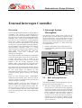
Finally, an enhanced mode is provided from the
External Interrupt Controller Block. This mode
supports multiple interrupt vectors for the 8051
external interrupt sources. That is, only one interrupt
vector each external interrupt input is provided by the
on-circuitry when the interrupt routine is called. If the
enhanced mode is disabled, the programmer would
have to identify which of the nine new sources has
caused the interrupt. This mode is called normal or
basic mode.
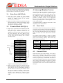
In the enhanced mode, a user-definable vector table is
provided (located in the SFR map of the 8051), and
no action from the programmer is needed, since the
interface selects the corresponding vector. This
operation is totally transparent to the mP8051 as long
as the register is multiplexed via hardware. The
corresponding flag in the Interrupt Status Register is
also cleared when the service routine is vectored to,
only if the interrupt was transition-activated.
Semiconductor Design Solutions
System Control Register 3 (h02 after Reset,
12x8 device)
Address
$9B
Name
RG3
Bit
INTM
RG3.7
RG3.6
RG3.5
RG3.4
RG3.3
RG3.2
CM1
RG3.1
CM0
RG3.0
Address
$A7,$A6
Name
VHW1
Byte
$A6
$A7
VHW1L
VHW1H
The Global Interrupt system of the FIPSOC is
controlled using registers located in the SFR map.
These registers can be divided into three groups:
ü Original 8051 registers used to control the on-core
interrupt system of the 8051 (see Microprocessor
Document),
ü Interrupt related Registers included in the
different subsystems of the FIPSOC. These
registers are explained in their corresponding
Documents
(Configurable
Analog
Block
Document, Software Debugging Block Document,
Clock Generation Block Document, and PL Block
Document).
The SFR used to control the External Interrupt
Controller Block are described below:
Address
$A5,$A4
Name
VPLL
Byte
$A4
VPLLL
$A5
VPLLH
Description
PLL
Interrupt
Vector.
Pseudovector used when
extended interrupt mode is
enabled (INTM = 1),
external
interrupt
and
PLLint are enabled and an
Interrupt
from
PLL
happens.
PLL Interrupt Vector Low
Byte
PLL Interrupt Vector High
Byte
Chapter 6. External Interrupts Controller
Description
HW Interrupt Vector 1
Pseudovector
used
when
extended interrupt mode is
enabled (INTM = 1), external
interrupt is enabled and
a) HW1int are enabled and an
Interrupt from the PLblock
happens; or
is
disabled,
b) HW1int
BOOTint is enabled and an
the communication system
produce
HW1 Interrupt Vector Low Byte
HW1 Interrupt Vector High Byte
Clock Interrupt Vector (h0000 after Reset)
Address
$AD,$AC
Name
VCLK
Byte
$AC
$AD
VCLKL
VCLKH
Description
CLK
Interrupt
Vector.
Pseudovector
used
when
extended interrupt mode is
enabled (INTM = 1), external
interrupt and CLKint are
enabled and clocks are frozen,
either
by
software
or
hardware
CLK Interrupt Vector Low Byte
CLK Interrupt Vector High Byte
Programmable Hardware vector 2 (h0000 after
Reset)
Address
$AF,$AE
PLL Interrupt Vector (h0000 after Reset)
Interrupt mode. If 1, extended
interrupt vectors mode is
entered, if 0, basic 8051interrupt mode is selected
External Memory Compatible
map bit 1
External Memory Compatible
map bit 0
Programmable Hardware vector 1 (h0000 after
Reset)
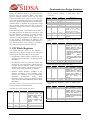
2. EIC Block Registers
ü EIC Registers used to control this block. The
registers are: two mask and two polarity registers
(one pair for each channel) used to control each
interrupt source signal, and the Interrupt Status
Register from which information is obtained.
Description
System Control Register 3
Name
VHW2
Byte
$AE
$AF
VHW2L
VHW2H
Description
HW2
Interrupt
Vector.
Pseudovector
used
when
extended interrupt mode is
enabled (INTM = 1), external
interrupt and HW2int are
enabled and an Interrupt from
the PLblock happens through
HW2INT input.
HW2 Interrupt Vector Low Byte
HW2 Interrupt Vector High Byte
4