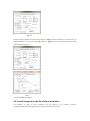
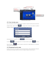
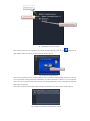
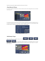
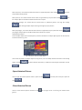
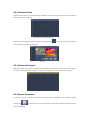
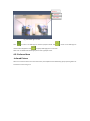
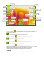
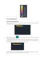
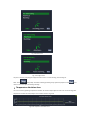
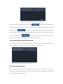
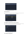
1
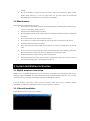
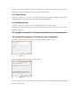
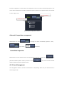
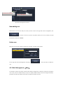
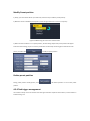
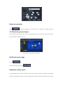
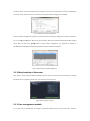
USER MANUAL Software product of IR239B In Electrical system Thanks for selecting us, we advise you to read the user manual carefully before using the camera, which will help you to use it properly. Please contact us if you have any questions. Copyright 2014, Wuhan Guide infrared Co., Ltd; All rights reserved worldwide. All trademarks and trade names or company names referenced herein are used for identification only and are the property of their respective owners. Legal disclaimer: The manual must not, in whole or part, be copied, photocopied, reproduced or transmitted to any electronic medium or translated into any language or computer language in any form or by any means, electronic, magnetic, optical, manual or otherwise, without the prior written permission of Guide Infrared Co., Ltd. The manual is made for the customers to use or know the products, and we will do our best to ensure the accuracy of the content, but can’t guarantee the integrity. Guide Infrared Co., Ltd reserved the right to continue updating or upgrading the specifications and /or functionality at any time without prior notice. Edition: IR239B in Electrical System, 2014.8.1 Rev. 1 Table of Contents 1. General .................................................................................................................................................................................... ... 4 2. Operation Specification ............................................................................................................................................................... 4 3. System Installation Instruction .................................................................................................................................................... 5 4. Client Functional Instruction ........................................................................................................................................................ 9 Automatic inspection management .............................................................................................................................................. 25 Immediate Inspection .................................................................................................................................................................... 25 New adding user............................................................................................................................................................................ 26 Delete user .................................................................................................................................................................................... 26 4.5.3 Mail Management(New) ................................................................................................................................................. 26 Newly adding receiver mail box ..................................................................................................................................................... 27 Modify receiver mailbox ................................................................................................................................................................ 27 Delete the receiver mailbox ........................................................................................................................................................... 27 Create sender mailbox ................................................................................................................................................................... 27 Modify Sender mailbox.................................................................................................................................................................. 28 4.5.4 Monitoring Device Management .......................................................................................................................................... 28 Device type adding ........................................................................................................................................................................ 29 Device type modify ........................................................................................................................................................................ 29 Device type delete ......................................................................................................................................................................... 29 Device adding ................................................................................................................................................................................ 29 Device modify ................................................................................................................................................................................ 29 Device delete ................................................................................................................................................................................. 29 4.5.5 Monitoring position management ........................................................................................................................................ 30 Add preset ..................................................................................................................................................................................... 30 Modify Preset position .................................................................................................................................................................. 31 Delete preset position ................................................................................................................................................................... 31 Add task chain ............................................................................................................................................................................... 32 Modify task chain .......................................................................................................................................................................... 32 Delete the task chain ..................................................................................................................................................................... 33 Modify the layout image ............................................................................................................................................................... 33 Modify the camera layout ............................................................................................................................................................. 33 5. Function Description of Server .................................................................................................................................................. 34 1. General Infrared is the parts of the electromagnetic spectrum, the infrared system is used for infrared radiation detection purpose. According to Planck's radiation theory, all object that his temperature is greater than absolute zero all can radiate electromagnetic energy, the radiation intensity of the object is related to the temperature and the object surface radiation ability, and the distribution of radiation spectral is closely related to the object temperature IR239B power monitoring thermal camera is the newly generation of power industry monitor thermal imager developed by Wuhan Guide Infrared Co., Ltd. The camera combine imaging, temperature & alarm analysis all function into one, cooperated with substation temperature monitoring system software developed by Guide company, to form a reliable performance infrared temperature monitoring system , while the system have a TCP/ IP interface to realize local and network control together, providing software development kit (SDK), easy integrated into TCP / IP networks. Main function & characteristics of IR239B power monitor thermal camera include: with PTZ, has a flexible visual field, horizontal rotation angle of 0 ° ~ 360 °, tilt angle of rotation of -60 ° ~ +20 °; Monitor with 50 preset positions, and a motor focus preset position; Adopt two kinds of lens( infrared and visible light), can perform real-time visible and infrared video display to the monitoring scenery, can step focusing, Auto focus online real-time temperature analysis, with two shift temperature range, without attenuation sheet temperature range: 0 ℃ ~ 150 ℃; without attenuation sheet temperature range: 150 ℃ ~ 350 ℃; Adopt two kinds of output interface (digital video output and analog video output) can realize monitor remote control (sleeping / wake up), high temperature alarm, timing detection, the maximum temperature tracking and any point temperature analysis in digital image; can realize auto inspection of tasks presets, automatic capture, automatic over-temperature alarm infrared images can be stored, playback infrared photo, drawing on temperature trends image according to historical photo, perform infrared video recording and video playback; remote image adopt model( analysis first, compress second, transport last) Device Operating temperature -20 ℃ to 50 ℃; 2. Operation Specification 2.1 Cautions Do not point the camera at very high-intensity radiation sources, such as the sun, carbon dioxide lasers, arc welders, otherwise the detector in the camera may be permanently damaged. Do not point the camera at high-temperature object during boot-up. Put the camera in the protective packing box during the transportation or the camera not used. Please prevent the camera from big weight, strenuous vibration and soaking, which will cause damage. Do not disassemble or attempt to open the camera under any circumstances. Please contact Wuhan Guide Infrared Co., Ltd for any repair issues. For any fault caused by un-authorized disassembling, the manufacturer is not to take any responsibility. 2.2 Maintenance Please follow the cautions strictly at any time: All User Manuals and leaflets should be read thoroughly before proceeding with operation of the camera. If any problems, please contact us. Keep the camera stable during the operation. Strictly prohibit the working environment beyond the limited environmental conditions specified by the camera. Do not use the power which doesn’t match the camera. Do not switch on or off the camera frequently. The interval time can’t be less than 20 seconds. Protect the cable connected to the camera. Don’t scrub the camera with chemical solvent, diluents, etc. please scrub it with clean, soft and dry cloth. Do not touch the lens with hands. Be careful while cleaning them with professional lens paper. Don’t clean the lens too vigorously, which can damage the anti-reflective coating. Replace the desiccant in the monitoring camera every 3 month. Use the backup copy of the data every 3 month to prevent the system crash, and ensure to have more than 20G storage space in polling picture storage area. 3. System Installation Instruction 3.1 MySQL database instruction MySQL.exe is an executable program that can be unzip itself. The program will automatically install into the catalogue: program files\MySQL. The system will start the service automatically after installation. The user name and password is root and 0 when visit MySQL in Configuration Management System. If manual operation, stop service, restart service are needed, please enter into the catalogue: program files\MySQL, you will find the following three files: inst.bat, stopsvr.bat, restart.bat. 3.1.1 Manual Installation 1). Double click inst.bat to enter into the interface It prompts reinstall the database might cause damage to your previous version. If enter Y (Be careful), the database will reinstall to the original state. If enter N, the interface will quit. 3.1.2 Stop Service Double click stopsvr.bat to stop the service of MySQL, meanwhile the MySQL service will be removed. If completed delete is needed, please delete the catalogue: program files\MySQL. 3.1.3 Restart Service Double click restart.bat to restart the service, the MySQL service can be reused at present. (Note: If the installation is terminated because of access denied when starting service, please close the antivirus program and reinstall.) 3.2 Installation Instruction of Electricity Monitoring System Application 3.2.1 Install The Setup.exe In The File of Server Installation. 1). Double click setup.exe to enter the interface of system installation. Shows as Fig. 3.1 Fig. 3.1 2). Default language is English, click “Next” shows as Fig.3.2 Fig. 3.2 3). Click “Next”, and then click “Browse” to choose folder. Such as C:\Program Files\Power Monitoring System\ .Shows as Fig. 3.3 Fig. 3.3 4). Click “Next”, shows as Fig. 3.4 Fig. 3.4 5). Click “Confirm”, installation complete, and click “Close”. Shows as Fig. 3.5 Fig. 3.5 6). Run the program in the installation dictionary such as D:\Program Files\Power Monitoring System \Server\ElectricControlServerConfig.exe. Firstly configure “Pic save path”. The default save path is e:\Photo. Show as Fig. 3.6. You can change the save path to “D:\Program Files\ Power Monitoring System\Server\photo”. (Please change other setting under professional guidance) Fig. 3.6 And then configure database. The default name of server is【.】The ordinary configuration is “Server Name”, use MySQL Certification: The user name is 【root】,password is 【0】.Shows as Pic 3.7 (Please change other configs under professional guidance) Fig. 3.7 7). Server installation completion 3.2.2 Install setup.exe in the file of client installation The installation is similar to server installation. Run the program in the installation dictionary D:\ProgramFiles\Power Monitoring System\Client\Electric Control Client Config.exe. Firstly configure “Pic save path”, it’s the same with system configuration. The default save path is e:\Photo that can be changed to D:\Program Files\ Power Monitoring System\Client\photo. (Please change other settings under professional guidance). 4. Client Functional Instruction 4.1 Client interface Start Client, the interface shows as Fig. 4.1. User only can enter system to operate via input right username and password. The system can supply relevant user function according to user’s type via different usernames and passwords of different users. Now it is introduced as administrator function. Fig. 4.1 The updated interface of Client program Fig. 4.2 The login interface of client program The user only is allowed to enter the system via input right username and password after updating complete. Enter the Client interface after passing user authentication. There are four parts of Client Interface: Title Menu, Equipment Function Menu, Display Interface and User Function Menu. Show as Fig. 4.3. User Function Menu Equipment Title Menu Function Menu Display Interface Fig. 4.3 Main interface of Client 4.1.1 User function menu Unser Function Menu includes two options: Password modification and Volume control (control the volume of equipment alarm) .Click the button on top right corner and enter the interface of password modification. However, it needs to provide the right original password. Show as Pic 4.4 Fig. 4.4 Main interface of password modification Enter right original and new password and click The button , successfully modify password. on the top right corner is the system volume at present. volume is turned on, means the means the volume is turned off. It can switch between turn on and off the system volume via click the button 4.1.2 Equipment function menu Equipment Function Menu lists equipment name and infrared equipment name that administrator saved, the latest temperature will appears behind the names after checking the equipments, Shown as Fig. 4.5: Equipment Type Equipment Name Infrared Equipment Name Fig. 4.5 Equipment Function Interface When mouse moves onto one equipment name except infrared equipment name, an icon appears on the right display interface to mark the equipment location. Show as Fig. 4.6: Equipment location Fig. 4.6 Appears equipment mark When click one equipment name, the system will skip into the interface of historical data analysis, and count the current equipment checking information. Meanwhile, the clicked equipment is pitched on in the equipment menu that is on the right of historical data analysis. The checking information only can be gathered via provide beginning and ending time. The function of historical data analysis will be introduced in detail later. Function interface shows as Fig. 4.6: Fig. 4.6 Skip to the interface of historical data analysis When click the infrared equipment in the equipment menu, the system will automatically click to real-time interface, and display the equipment current condition. System will automatically open infrared equipment to observe the real-time image. The function of real-time video will be introduced in detail later. Function interface shows as Fig. 4.7: Fig. 4.7 Skip to the interface of real-time video 4.2 Historical Data Analysis Historical data analysis is the function of analyzing and gathering the data that created during equipment checking. It is used for helping user to check historical data of equipment checking. It includes three functions: Data List, Historical Curve, and Advanced Compare. The main interface of historical data analysis module shows as Fig. 4.8 Time Selection Menu Equipment Menu Gathering interface Fig. 4.8 Main interface of historical data analysis User can gather all equipments needed to do historical data analysis via choose equipment menu. Click check box to choose the needed equipments to gather. means selected, means unselected. User also can select all the same type of equipment via click equipment type name. Shows as Pic 4.9 Fig. 4.9 Select same equipment type Select starting and ending time of equipment condition gather in the time selection menu. User not only can input the date manually, but also click to select the date to inquire. Show as Figure: And click to gather equipment condition information. Gathering interface show as Fig. 4.10 Fig. 4.10 Equipment information gathering interface Note: User can click to gather the equipment information of last week. 4.2.1 Data List Data list is equipment temperature statistic during checking that includes equipment name, checking time, equipment temperature, inner temperature of camera, inner humidity of camera. The interface as Fig. 4.11: Fig. 4.11 Data list gathering interface ·Temperature Display Status User can choose temperature display status of gathering equipment information via choose. ·View Historical Picture The system will display automatically the relevant historical picture after clicking date-in-line, the interview shows as Fig. 4.12 Fig. 4.12 Display interface of historical picture The module will display the infrared pictures which created during equipment checking. Visual light pictures are on the left, infrared pictures are on the right. The basic information of picture is on the left bottom which includes maximum, minimum and average of picture. Show as following Figure: Fig. 4.13 Basic information of picture ·Add Analysis Target User can reanalyze the historical picture via click , , , , . User input relevant object information in the following interface of monitor object information, and click analytic object that wanted to be plotted. And plot analytic object on the picture. Show as Fig. 4.14 Fig. 4.14 Add analytic object When plot point, user should click left mouse button at appointed position after clicking analytic object will be plotted When plot line, user should click left mouse button at appointed line joint point after clicking , the point , plot line analytic object via double click left mouse button at end point. When plot rectangle, user should click left mouse button at appointed position and drag after clicking , plot rectangle analytic object via enlarge rectangle to proper position. When plot polygon, user should click left mouse button at appointed line joint point after clicking , plot polygon analytic object via double click left mouse button at end point. ·Modify Analytic Object Choose analytic object via click infrared picture, relevant information of analytic object appears at the bottom of interview. Shows as Fig. 4.14 Fig. 4.14 Chosen state of analytic object User moves the position of analytic object via drag mouse, also can modify relevant information of monitoring object, and click to amend relevant information, or delete the analytic object information via click . ·Open Historical Picture User can open the infrared pictures saved in system via click , and save picture into your system via click ·Close Historical Picture User can close historical picture module via click gesture. at top right corner or fast drag and release mouse 4.2.2 Historical Curve Historical curve module is to display temperature difference during equipment checking via time shaft picture. Main interface shows as Fig. 4.15: Fig. 4.15 Interface of historical curve Check the corresponding picture that created during checking via click in the Fig. 4.16. The basic operation is the same with introduction in last chapter Fig. 4.16 4.2.3 Advanced Compare Advanced compare is to compare the temperature with different equipment at the same time. It’s convenience for user to analyze equipment temperature. It needs user to choose two or more equipments. See Fig. 4.17: Fig. 4.17 The interface of advanced compare 4.2.4 Report Generation The data-in-line will be in chosen state via click in data list module. (The background color changed to yellow). And then click electrical equipment) to choose the type of report generation. (Only support standard diagnostic report of . Click to generate relevant report. The interface shows as following picture Fig. 4.18 interface of report generation 4.3 Real time video User can check equipment status via real time video that includes visible light area, infrared area, equipment tree menu, display area of temperature variation. The main interface shows as Fig.4.19 Infrared area Visible light area Temperature variation area Equipment Menu Fig. 4.19 Real time video interface 4.3.1 Visible Light Area When user moves the mouse onto the visible light area, the face plates will automatically popup operating button of visible light area. Show as Fig. 4.20 Zoom in Zoom out Full screen Fig. 4.20 Visible light interface Click to zoom in of visible light to observe equipment detail. Click observe whole equipment. Click to zoom out of visible light to to display visible light part in full screen. Note: User can double click visible light part to enter of quit full screen. 4.3.2 Infrared Area ·Infrared Picture When user moves the mouse onto the infrared area, the faceplates will automatically popup operating button of infrared area. Show as Fig. 4.21 Near focus Point Far focus Line Auto focus Rectangle Shutter Circle Filter Brush Delete single analytic object Photograph Polygon n Open picture Delete all Console control Video Play area Full Screen Fig. 4.21 Infrared interface The operating area of infrared lens is on the top left which includes near focus, far focus, auto focus etc that are used for modifying sharpness of picture. The operating area of infrared picture is on the bottom left which includes photograph, open picture, video, play, full screen etc. Hereinto is used for photographing infrared and visible light area, the photos can be saved as format of jpg, bmp and ira. is used for opening the ira pictures that can analyze historical picture Note: The icon will change to after opening picture; it is used for switch to real time video. is used for videotaping infrared area, saved format is .irh. Note: The icon will change to after videotaping; it is used for stop to real time video. is used for opening irh file that can analyze historical video. Note: The icon will change to after playing; it is used for stop to real time video. Operating area of analytic object is on the top right which includes point, line, rectangle, circle, and polygon. Operating procedure is the same with historical picture analytic software. See as chapter4.2.1 Console control area is in the bottom that is used for operating console to eight directions ·Color Bar Color bar is used for displaying color of infrared picture imaging result, the interface show as Fig.4.22 Fig.4.22 Color Bar 4.3.3 Equipment Menu ·Open Infrared Equipment User moves mouse onto the name of infrared equipment where the circle appears. It means countdown of opening the equipment Fig. 4.23 Tree menu of monitory point Note: When the circle change to that means the equipment can be opened. If the mouse left during the situation, it will stop opening. The equipment under infrared equipment is allowed to open after opening infrared equipment. Move the mouse onto anywhere of equipment to wait the circle close, system will remind whether run to the presetting bit, infrared equipment start to check the equipment after confirming to run. Fig. 4.24 presetting position is chosen When infrared equipment starts to check presetting position, it will be finished into three parts that are: console rotation, auto focus, picture match. The interfaces show as Fig. 4.25, 4.26, 4.27 Fig. 4.25 Console rotation Fig. 4.26 Auto focus Fig. 4.27 Image match The part is used for prompting the equipment status such as console rotating, auto focusing etc. Note: Click will forcibly terminate checking presetting bit of infrared equipment. Click will return to tree menu after terminating checking. · Temperature Variation Area The area is used for gathering temperature variation of chosen analytic object on time scale. Conveniently gather temperature variation of analytic object. The interface shows as Fig. 4.28 Fig. 4.28 Temperature variation area Note: When analytic area of infrared parts is chosen, the area will automatically gather temperature variation. When analytic area is canceled, the area will re-gather temperature variation. Click on the top right to set temperature variation area, the setting interface shows as following Figure: Hereinto, Period means interval time of gathering temperature of the area. Max Y and Min Y mean measurement range of temperature. Click to restore default settings. 4.4 Message Window Message window is used for gathering some system message of operation and equipment, it’s convenience for administrator to contact with user and for user to handle alarm message of infrared equipment. The interface shows as Fig. 4.29: Fig. 4.29 interface of message window Note: The number of information window means how many messages should be handled. 4.4.1 Power device detection information Power device detection information module is applied for the course of the current user; the infrared equipment inspection for the temperature exceeds the alarm temperature to make summary display. Interface is shown as Fig.4.30: Figure 4.30 Power device detection information interface Daily record have the response operation button, which is the view corresponding historical inspection pictures , after clicking, the system will automatically jump to the historical data analysis module and displays the picture。 Refers to view the current status of the device, after clicking, the system will automatically jump to the real-time interface module, and automatically run to the preset position, observe the corresponding equipment Which means that the user already knows the message, and notifies other users to make relevant handling to have related to the current fault. 4.4.2 Infrared device alarm information Infrared device alarm information module is used for device internal alarm summary in the course of the current device using process ,such as over-high humidity etc, the interface is shown as Fig. 4.31: Fig. 4.31 Infrared device alarm information interface 4.4.3 System information System messages module is used for all message summary sent from the administrtor to the user. The administrator can send message to the current online users through the server, all messages will be summarized in this module. Such as Figure 4.32 shows: Fig.4.32 system information interface 4.4.4 Operation log Operation log module is used for all operation information summary apply for the current user, the user can see what they have done by viewing the module. The interface is shown as Figure 4.33: Fig. 4.33 system information interface 4.5 Configuration (administrator-specific operations) When a user logs in as administrator, the module will automatically appear in the interface, which is mainly used for administrators to manage the tasks of infrared device, the interface is shown as Figure 4.34: Fig. 4.34 Configuration interface 4.5.1 Inspection Configuration Inspection configuration is mainly used for the management to the current device automatically inspection, also can be used for administrators to make an immediate inspection operation to the appointed device, the interface is shown in Figure 4.35: Auto polling setting Device tree menu Fig. 4.35 Option Configuration Interface Automatic inspection management Administrators can click to manage the device automatically inspection,which, Is open status, is close status。 Immediate Inspection Administrators can select the device in the corresponding device tree menu, and then click perform immediate inspection function, and then can click module to observe the whole inspection process. to Jump to the real time interface 4.5.2 User Management User management module is used for the administrator to add /modify/ delete user, the interface shown in shown as Figure 4.36: Currently user summary Account Management Fig 4.36 User management interface New adding user Administrators can enter the newly user name you want to add on the right side account management ,click To create a new user, At prsent only allows ordinary users to be created, the initial password of created user is 888888. Delete user Select the user you want to delete in the left user summary, as shown in Figure below On the right side Account Management will appear , Click this button to delete the user. 4.5.3 Mail Management(New) The module is used for the receiver and the sender mailbox configuration, in which the receiver that include the user's name, the user's mailbox address, and you can specify multiple receivers. Sender including email address, password, and mail server address, the sender can specify an interface as shown. Summary of the receiver's mailbox Receiver Management Sender management Fig 4.37 Mail management interface Newly adding receiver mail box Administrators can enter the appropriate user name and e-mail address on right side user management to click to add a receiver Modify receiver mailbox Administrators can click the mail box information that to be modified on the left side receiver mailbox summary, to make the user's information on the right user management interface, as the below photo showing: Then enter the information you want to modify, then click 。To make relevant modify operation for the receiver mailbox. Delete the receiver mailbox In the step of modifying the receiver mailbox, the administrator can click to delete the relevant information of mailbox. Create sender mailbox When the sender is created, administrators can input relevant user name & email address through the right side user management to click to create sender. Modify Sender mailbox Before the sender has been created, the administrator can click to directly modify the sender information. 4.5.4 Monitoring Device Management This module is mainly used for the corresponding management operations of the device type and device name, the interface is shown as Figure 4.37: Device Type Management Device tree menu Device Management Fig. 4.38 Monitoring Device Management Interface Device type adding Administrators can enter the device type name you want to add, warning temperature and alarm temperature on the right side device type management, and then click to add a new device type Device type modify Administrators can click the device type under the root directory of device tree type menu on the left side , make the corresponding information of the device type displayed on the right side device type management, and then modify the information on which ,click to do modify operation to the information of one device type。 Device type delete During the device type amending process, the administrator can click to do the delete operation to device type information. Device adding Administrators can enter the device name that you want to add, warning temperature and alarm temperature on the right side device management , and select the device type, then click device type. to add a newly Device modify Administrator can click the device under device tree menu sub node on the left side. Make the device relevant information displayed on the right side device management, then make modify to the information in which, click to do the modify operation to a device type information Device delete During the device amending process, the administrator could click to do the delete operation to device information 4.5.5 Monitoring position management Monitoring position management module is mainly used for administrator to set the infrared device preset position operation; the interface is shown as Figure 4.38: Device tree menu: Infrared Image area: Monitoring points tree menu Monitoring point operation area Fig. 4.39 Monitoring position Management interface Add preset 1) Firstly, open the infrared device. Note: move the mouse to the root of the infrared device, and then open the infrared device when the right side circle is closed. Fig. 4.40 Monitoring points tree menu interface 2) Click the device you want to monitor on the right side existing device tree menu, or fill in newly power device in the preset position editing area (After save the preset position, the newly filled power device would be auto added to the device type database , also appear on the right side existing device tree menu Note: The device under yellow background inside the existing device tree menu on the right side indicate that the device has been added to the preset position, the preset position couldn’t be added any more, only can be modified. The modify method would be introduced later. 3) Adjust the infrared device to the monitoring position, use the specified point, line, rectangle, ellipse, polygon tool to draw down the monitored device within the infrared image display area 4). Click the save position, then saved preset position。 Modify Preset position 1) Firstly, open the infrared device. (The same way as the first step to add the preset position) 2) Move the mouse to modified preset position, when the right side circle is closed to run preset). Figure 4.41Monitoring point tree menu selected status 3) When the infrared device run to a preset position, the monitoring object of the preset position will appear inside the infrared image, so you can use the preset editor to add newly monitoring point inside the infrared picture, and then click to modify the preset position. Delete preset position During preset position modify process, click to do delete operation on the current preset position. 4.5.6 Task trigger management The module is mainly used to set the task chain during the automatic inspection of IR camera, and the interface is indicated in Fig. 3.37: Preposition list Task list Fig.4.42 Task trigger management interface Add task chain 1) Click the added tasks in the tree menu, and the selected tasks are in the yellow background. 2). Input the relative information of the tasks in the task name editing area. 3). Click “Add”, the newly-added task information will be added into the task list on the left side. Modify task chain 1). Click the modified or deleted task chain in the task list. 2). The relative information will occur in the task name editing area. Input the relative modified information in the editing area, and then click to finish the modification. Delete the task chain Click during the modification of the task chain to complete the “delete” operation. 4.5.7Monitoring camera layout The monitoring camera layout module is mainly used to set the positions of the users and the various cameras, and the interface is indicated in Fig. 4.42. Fig. 4.43 Monitoring camera layout module Modify the layout image 1). Click 2). Select the load picture and click Modify the camera layout 1). newly-added camera: hold down the left key of the mouse in the left tree menu, and drag into the response position in the right layout picture, and release the right key, and then put the newly-added camera name into the camera picture. 2). modify the existing camera position: in the layout picture, move the mouse to white circle, and the hint will occur. Select the corresponding camera; drag the mouse to modify the existing camera position. 3). Delete the existing position: in the left tree menu, the equipment in the yellow background indicates that the positions have been added. Click this equipment in the yellow background, and the background of equipment name becomes black and the position will be deleted in the layout drawing. Note: For the above operations, click to be effective. 4.6 Exit System In the client mode, click “spacing” to exit the system. 5. Function Description of Server 5.1 Server maintenance 5.1.1 Server configuration After the server is installed, make configuration on the server during the first boot-up. Enter and find ElectricControlServerConfig.exe via the start menu or via server side installation path, indicated in Fig. 5.1, and the server name is the server IP address. If the computer is the server, input IP address, and then input MySQL ID check user name, save after the test is successful, and the IR parameter configuration is available. Fig. 5.1 Interface of server configuration Click IR parameter configuration interface and enter infrared and visual light configuration interface, indicated in Fig. 5.2. Click【Search】button. After the search is finished, define the IP address below IR Device Mac and VLD Device Mac, and then click 【Add】button to finish camera configuration. The appointed IP address of 192.168.1.63 and 192.168.1.12 respectively stands for those of IR and VLD equipment. Fig.5.2 Interface of IR and VLD configuration 5.1.2 Main interface of the server Start “Server”, and the interface effect is indicated as follows. Users can check the set task information, including Equipment status, equipment temperature, and next start-up time and so on. Fig. 5.3 Main interface of server 5.1.3 User management module It is mainly used for administrator to manage the occupied equipment status by the active users. Input the correct password, and enter the module, and the interface is shown in Fig. 5.4. Fig.5.4 User management log-in interface After log-in, the active user is on the left side, the equipment using situation by the users is on the right side. On the right low side is about the password modification situation by the administrator, and the interface is shown in Fig. 5.5. Fig. 5.5 Main interface for user management Wuhan Guide Infrared Co., Ltd Add: No.6 Huanglong Hill South Rd, Wuhan, 430205, P.R.C Fax: +86-27-8129-8345 Email: [email protected] www.guideinfrared.com