1
2354235 11/2008
Altivar 61/71
Modbus TCP/IP card
User manual
VW3A3320
HRB10064
02/2013
www.schneider-electric.com
efesotomasyon.com
The information provided in this documentation contains general descriptions and/or technical characteristics
of the performance of the products contained herein. This documentation is not intended as a substitute for
and is not to be used for determining suitability or reliability of these products for specific user applications. It
is the duty of any such user or integrator to perform the appropriate and complete risk analysis, evaluation and
testing of the products with respect to the relevant specific application or use thereof. Neither Schneider
Electric nor any of its affiliates or subsidiaries shall be responsible or liable for misuse of the information
contained herein. If you have any suggestions for improvements or amendments or have found errors in this
publication, please notify us.
No part of this document may be reproduced in any form or by any means, electronic or mechanical, including
photocopying, without express written permission of Schneider Electric.
All pertinent state, regional, and local safety regulations must be observed when installing and using this
product. For reasons of safety and to help ensure compliance with documented system data, only the
manufacturer should perform repairs to components.
When devices are used for applications with technical safety requirements, the relevant instructions must be
followed.
Failure to use Schneider Electric software or approved software with our hardware products may result in
injury, harm, or improper operating results.
Failure to observe this information can result in injury or equipment damage.
© 2012 Schneider Electric. All rights reserved.
efesotomasyon.com
7DEOHRIFRQWHQWV
Important Information _________________________________________________________________________________________ 5
About the book ______________________________________________________________________________________________ 6
Before you begin_____________________________________________________________________________________________ 7
Documentation structure_______________________________________________________________________________________ 8
Introduction _________________________________________________________________________________________________ 9
Presentation _____________________________________________________________________________________________ 9
Notation ________________________________________________________________________________________________ 9
Hardware setup ____________________________________________________________________________________________
Receipt ________________________________________________________________________________________________
Hardware description _____________________________________________________________________________________
Installing the card in the drive. See the Installation Manual (1760643 or 1760655). _____________________________________
10
10
10
11
Connecting to the Ethernet network _____________________________________________________________________________ 12
Card RJ45 connector pinout ________________________________________________________________________________ 12
Example of connection to an Ethernet network _________________________________________________________________ 12
Ethernet menu _____________________________________________________________________________________________
Access to Ethernet menu via graphic display terminal ____________________________________________________________
Access to Ethernet menu via the integrated display terminal _______________________________________________________
Ethernet menu parameters _________________________________________________________________________________
14
14
14
15
Configuration ______________________________________________________________________________________________
List of functions to be configured ____________________________________________________________________________
Detail of the configuring parameters__________________________________________________________________________
Reserving control ________________________________________________________________________________________
Configuring IO Scanning___________________________________________________________________________________
Configuring the control ____________________________________________________________________________________
Configuring the fault management ___________________________________________________________________________
Configuring monitored parameters ___________________________________________________________________________
20
20
21
23
23
24
27
29
Diagnostics ________________________________________________________________________________________________
Signalling LEDs _________________________________________________________________________________________
Available information _____________________________________________________________________________________
Monitoring the control _____________________________________________________________________________________
Troubleshooting the communication fault ______________________________________________________________________
Troubleshooting the card fault ______________________________________________________________________________
30
30
31
31
32
33
Software setup _____________________________________________________________________________________________ 34
List of services supported __________________________________________________________________________________ 34
TCP connections ________________________________________________________________________________________ 34
Modbus TCP server _________________________________________________________________________________________
Modbus TCP frames______________________________________________________________________________________
Drive Modbus servers_____________________________________________________________________________________
Ethernet card parameters __________________________________________________________________________________
List of Modbus functions supported __________________________________________________________________________
“Read Holding Registers” (3) function ________________________________________________________________________
“Write Single Register” (6) function___________________________________________________________________________
“Write Multiple Registers” (16 = 16#10) function ________________________________________________________________
“Read/Write Multiple Registers” (23 = 16#17) function____________________________________________________________
“Read Device Identification” (43 = 16#2B) function ______________________________________________________________
35
35
35
36
39
39
40
41
42
43
IO Scanning service _________________________________________________________________________________________
Presentation ____________________________________________________________________________________________
Periodic variables ________________________________________________________________________________________
Address table ___________________________________________________________________________________________
44
44
44
45
FDR service _______________________________________________________________________________________________
Presentation ____________________________________________________________________________________________
Local configuration _______________________________________________________________________________________
Downloaded configuration _________________________________________________________________________________
Periodic saving __________________________________________________________________________________________
Other commands ________________________________________________________________________________________
Configuration file_________________________________________________________________________________________
46
46
47
48
50
50
50
HRB10064 02/2013
3
efesotomasyon.com
7DEOHRIFRQWHQWV
Standard Web server ________________________________________________________________________________________
Web server functions _____________________________________________________________________________________
Applets ________________________________________________________________________________________________
Access to the Web server__________________________________________________________________________________
Web server user interface__________________________________________________________________________________
“Home” menu ___________________________________________________________________________________________
“Monitoring” menu________________________________________________________________________________________
“Diagnostics” menu_______________________________________________________________________________________
“Setup” menu ___________________________________________________________________________________________
“Security” Submenu ______________________________________________________________________________________
“Documentation” menu ____________________________________________________________________________________
51
51
52
53
54
54
54
58
60
68
69
FTP server ________________________________________________________________________________________________ 70
Downloading from the Web server ______________________________________________________________________________ 72
SNMP agent _______________________________________________________________________________________________ 76
Setup using PL7 ____________________________________________________________________________________________ 78
Setup using Concept ________________________________________________________________________________________ 84
Setup using ProWORX NxT ___________________________________________________________________________________ 85
4
HRB10064 02/2013
efesotomasyon.com
,PSRUWDQW,QIRUPDWLRQ
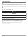
127,&(
Read these instructions carefully, and look at the equipment to become familiar with the device before trying to install, operate, or
maintain it. The following special messages may appear throughout this documentation or on the equipment to warn of potential
hazards or to call attention to information that clarifies or simplifies a procedure.
The addition of this symbol to a Danger or Warning safety label indicates that an electrical hazard exists, which will result
in personal injury if the instructions are not followed.
This is the safety alert symbol. It is used to alert you to potential personal injury hazards. Obey all safety messages that
follow this symbol to avoid possible injury or death.
'$1*(5
'$1*(5 indicates an imminently hazardous situation, which, if not avoided, ZLOOUHVXOW in death or serious injury.
:$51,1*
:$51,1* indicates a potentially hazardous situation, which, if not avoided, FDQUHVXOW in death, serious injury or equipment
damage.
&$87,21
&$87,21 indicates a potentially hazardous situation, which, if not avoided, FDQUHVXOW in injury or equipment damage.
NOTICE
NOTICEis used to address practices not related to physical injury.
3/($6(127(
The word "drive" as used in this manual refers to the controller portion of the adjustable speed drive as defined
by NEC.
Electrical equipment should be installed, operated, serviced, and maintained only by qualified personnel. No
responsibility is assumed by Schneider Electric for any consequences arising out of the use of this product.
© 2012 Schneider Electric. All Rights Reserved.
HRB10064 02/2013
5
efesotomasyon.com
$ERXWWKHERRN
'RFXPHQW6FRSH
The purpose of this document is to:
• show you how to install theModbus TCP/IP card module on your Altivar 61 / 71,
• show you how to configure the Altivar 61 / 71 to use Modbus TCP/IP fieldbus.
127( Read and understand this document and all related documents (see below) before installing, operating, or maintaining your
ATV61 / 71.
9DOLGLW\1RWH
This documentation is valid for the Altivar 61 / 71 EtherNet fieldbus.
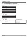
5HODWHG'RFXPHQWV
7LWOHRI'RFXPHQWDWLRQ
5HIHUHQFH1XPEHU
ATV61 Quick Start guide
S1B86974
ATV71 Quick Start guide
S1B86982
ATV61 > 75kW Installation manual
1760655
ATV71 > 75kW Installation manual
1755849
ATV61 0,37kW to 75 kW Installation manual
1760643
ATV71 0,37kW to 75 kW Installation manual
1755843
ATV61 Programming manual
1760649
ATV71 Programming manual
1755855
ATV71 S383 Programming manual
AAV49426
ATV71 Communication Parameters manual
1755861
ATV61 Communication parameters manual
1760661
ATV71 Integrated Modbus manual
1755863
ATV71 Modbus Plus manual
1755869
ATV71 Uni-Telway manual
1755867
ATV71 Modbus with Uni-Telway manual
1755875
ATV61/71 CC-Link manual
AAV49429
ATV61/71 Standard Fipio manual
1755883
ATV61 LonWorks card manual
1765273
ATV61 BACnet manual
1765274
ATV61/71 DeviceNet manual
1755877
ATV61 Metasys N2 manual
AAV33578
ATV61 APOGEE FLN P1 manual
BBV10543
ATV61/71 INTERBUS manual
1755871
ATV61/71 Profibus DP manual
1755873
ATV61/71 Profibus DPv1 manual
AAV52935
ATV61/71 Controller Inside manual
1757062
ATV61/71 CANopen manual
1755865
ATV61/71 EtherNet-IP manual
AAV68822
ATV61/71 Ethernet - Modbus TCP-IP manual
1755879
ATV61/71 Modbus TCP-IP manual - Daisy Chain Ethernet card manual
AAV69931
ATV61/71 ModbusTCP manual_VW3A3320
HRB10064
ATV61/71 EthernetIP manual VW3A3320
HRB10065
ATV61/71 LIFT Safety integrated function manual
S1A91443
ATV61/71 certificates, see www.schneider-electric.com
You can download the latest versions of these technical publications and other technical information from
www.schneider-electric.com.
6
HRB10064 02/2013
efesotomasyon.com
%HIRUH\RXEHJLQ
'$1*(5
81,17(1'('(48,30(1723(5$7,21
• Read and understand this manual before installing or operating the drive.
• Any changes made to the parameter settings must be performed by qualified personnel.
)DLOXUHWRIROORZWKHVHLQVWUXFWLRQVZLOOUHVXOWLQGHDWKRUVHULRXVLQMXU\
'$1*(5
+$=$5'2)(/(&75,&6+2&.(;3/26,2125$5&)/$6+
• Only appropriately trained persons who are familiar with and understand the contents of this manual and all other pertinent product
documentation and who have received safety training to recognize and avoid hazards involved are authorized to work on and with this
product system. Installation, adjustment, repair and maintenance must be performed by qualified personnel.
• The system integrator is responsible for compliance with all local and national electrical code requirements as well as all other
applicable regulations with respect to grounding of all equipment.
• Many components of the product, including the printed circuit boards, operate with mains voltage. Do not touch. Use only electrically
insulated tools.
• Do not touch unshielded components or terminals with voltage present.
• Motors can generate voltage when the shaft is rotated. Prior to performing any type of work on the product system, block the motor
shaft to prevent rotation.
• AC voltage can couple voltage to unused conductors in the motor cable. Insulate both ends of unused conductors of the motor cable.
• Do not short across the DC bus terminals or the DC bus capacitors or the braking resistor terminals.
• Before performing work on the product system:
- Disconnect all power, including external control power that may be present.
- Place a "Do Not Turn On" label on all power switches.
- Lock all power switches in the open position.
- Wait 15 minutes to allow the DC bus capacitors to discharge. The DC bus LED is not an indicator of the absence of DC bus voltage
that can exceed 800 Vdc.
Measure the voltage on the DC bus between the DC bus terminals using a properly rated voltmeter to verify that the voltage is <42
Vdc.
- If the DC bus capacitors do not discharge properly, contact your local Schneider Electric representative.
• Install and close all covers before applying voltage.
)DLOXUHWRIROORZWKHVHLQVWUXFWLRQVZLOOUHVXOWLQGHDWKRUVHULRXVLQMXU\
:$51,1*
'$0$*('5,9((48,30(17
Do not operate or install any drive or drive accessory that appears damaged.
)DLOXUHWRIROORZWKHVHLQVWUXFWLRQVFDQUHVXOWLQGHDWKVHULRXVLQMXU\RUHTXLSPHQWGDPDJH
:$51,1*
/2662)&21752/
• The designer of any wiring scheme must consider the potential failure modes of control channels and, for certain critical control
functions, provide a means to achieve a safe state during and after a channel failure. Examples of critical control functions are
emergency stop and overtravel stop.
• Separate or redundant control paths must be provided for critical control functions.
• System control channels may include links carried out by the communication. Consideration must be given to the implications
of unanticipated transmission delays or failures of the link.(1)
)DLOXUHWRIROORZWKHVHLQVWUXFWLRQVFDQUHVXOWLQGHDWKVHULRXVLQMXU\RUHTXLSPHQWGDPDJH
(1) For additional information, refer to NEMA ICS 1.1 (latest edition), “Safety Guidelines for the Application, Installation, and Maintenance of Solid
State Control” and to NEMA ICS 7.1 (latest edition), “Safety Standards for Construction and Guide for Selection, Installation and Operation of
Adjustable-Speed Drive Systems.”
HRB10064 02/2013
7
efesotomasyon.com
'RFXPHQWDWLRQVWUXFWXUH
The following Altivar 61 / 71 technical documents are available on the Web site www.schneider-electric.com.
b,QVWDOODWLRQ0DQXDO
This manual describes:
• How to assemble the drive.
• How to connect the drive.
b3URJUDPPLQJ0DQXDO
This manual describes:
• The functions.
• The parameters.
• How to use the drive display terminal (integrated display terminal and graphic display terminal).
b&RPPXQLFDWLRQ3DUDPHWHUV0DQXDO
This manual describes:
• The drive parameters with specific information (addresses, formats, etc.) for use via a bus or communication network.
• The operating modes specific to communication (state chart).
• The interaction between communication and local control.
b0RGEXV&$1RSHQ(WKHUQHW3URILEXV,17(5%868QL7HOZD\'HYLFH1HW0RGEXV
3OXV HWFPDQXDOV
These manuals describe:
• Connection to the bus or network.
• Configuration of the communication-specific parameters via the integrated display terminal or the graphic display terminal.
• Diagnostics.
• Software setup.
• The communication services specific to the protocol.
b$OWLYDU)0LJUDWLRQ0DQXDO
This manual describes the differences between the Altivar 71 and the Altivar 58/58F.
It explains how to replace an Altivar 58 or 58F, including how to replace drives communicating on a bus or network.
8
HRB10064 02/2013
efesotomasyon.com
,QWURGXFWLRQ
3UHVHQWDWLRQ
The Ethernet card (catalog number VW3 A3320) is used to connect an Altivar 61/71 drive to an Ethernet network using the Modbus TCP/IP
protocol and Transparent Ready services.
This communication option card is fully supported with the version V5.8 and above of the Altivar 61 firmware and with the version V5.7 and
above of Altivar 71 firmware.
The VW3 A3320 card is equipped with two shielded RJ45 Ethernet connectors.
The accessories for connection to the Ethernet network must be ordered separately.
The data exchanges permit full drive functionality:
• Configuration
• Adjustment
• Control
• Monitoring
• Diagnostics
The standard Web server (English only) provides access to the following pages:
• Monitoring
• Diagnostics
• Setup
• RSTP Management
Etc.
The standard Web server can be adapted or replaced by a customized server depending on the requirements of the application.
The graphic display terminal or the integrated display terminal can be used to access numerous functions for communication diagnostics.
1RWDWLRQ
'ULYHWHUPLQDOGLVSOD\V
The graphic display terminal menus are shown in square brackets.
Example: [1.9 COMMUNICATION].
The integrated 7-segment display terminal menus are shown in round brackets.
Example: (COM-).
The parameter names displayed on the graphic display terminal are shown in square brackets.
Example: [Fallback speed].
The parameter codes displayed on the integrated 7-segment display terminal are shown in round brackets.
Example: (LFF).
)RUPDWV
Hexadecimal values are written as follows: 16#
Binary values are written as follows: 2#
PC-Software: Commissioning Software
HRB10064 02/2013
9
efesotomasyon.com
+DUGZDUHVHWXS
5HFHLSW
• Check that the card catalog number marked on the label is the same as that on the delivery note corresponding to the purchase order.
• Remove the option card from its packaging and check that it has not been damaged in transit.
&$87,21
67$7,&6(16,7,9(&20321(176
The Modbus TCP/IP Ethernet card can be damaged by static electricity. Observe electrostatic precautions when handling and
installing the card.
)DLOXUHWRIROORZWKLVLQVWUXFWLRQFDQUHVXOWLQHTXLSPHQWGDPDJH
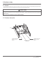
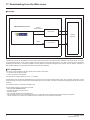
+DUGZDUHGHVFULSWLRQ
LEDs
Shielded female RJ45
Ethernet connector
(Port 2)
10
MAC address label
on the card
Shielded female RJ45
Ethernet connector
(Port 1)
HRB10064 02/2013
efesotomasyon.com
+DUGZDUHVHWXS
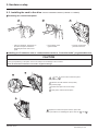
,QVWDOOLQJWKHFDUGLQWKHGULYHSee the Installation Manual (1760643 or 1760655).
b5HPRYLQJWKHFRQWUROIURQWSDQHO
• Using a screwdriver, press down on
the catch and pull to release the
left-hand part of the control front
panel
• Do the same on the
right-hand side
• Pivot the control front
panel and remove it
b,QVWDOOLQJDQ,2H[WHQVLRQFDUGDFRPPXQLFDWLRQFDUGRUD³&RQWUROOHU,QVLGH´SURJUDPPDEOHFDUG
&$87,21
5,6.2)'$0$*(727+(&211(&725
Ensure good positioning of the option card on the clasps to avoid damage to the connector.
)DLOXUHWRIROORZWKHVHLQVWUXFWLRQVFDQUHVXOWLQHTXLSPHQWGDPDJH
1 , 2 and 3 Remove the control front panel
(see previous page)
4 Install an encoder interface card (if used)
(see previous page)
5 Position the option card on the clasps
6 Then pivot it until it clicks into place
7 Replace the control front panel over the option card
(same procedure as for installing the option card, see 5 and
6 )
HRB10064 02/2013
11
efesotomasyon.com
&RQQHFWLQJWRWKH(WKHUQHWQHWZRUN
&DUG5-FRQQHFWRUSLQRXW
The Ethernet card is equipped with two shielded RJ45 connectors. The shielding is connected to the drive ground. The dielectric isolation
is 1500Vrms.
Use an STP (shielded twisted pair) Ethernet cable.
3LQ
6LJQDO
1
TD+
2
TD-
3
RD+
4
5
6
RD-
7
8........................1
8........................1
8
The transmission speed is detected automatically by the card (10 Mbps or 100 Mbps).
The card can operate in half duplex or full duplex mode, whether connected to a hub or a switch and regardless of the transmission speed
(10 Mbps or 100 Mbps). Devices of the network shall be all set to the same baudrate manually or all set to automatic bauderate detection.
1RWH RSTP function is not compatible with half duplex configuration.
The card supports the ETHERNET 2 frame format (IEEE 802-3 not supported). All devices involved in the RSTP topology shall be RSTP
capable and configured.
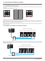
([DPSOHRIFRQQHFWLRQWRDQ(WKHUQHWQHWZRUN
PLC
Daisy chain and/or star topology
ATV61/71 ATV61/71 ATV61/71 ATV61/71 ATV61/71
Ethernet switch
1RWH: When the topology is a daisy chain, if one drive is turned off, the drive(s) next the drive powered off trip in CNF. To keep the integrity
of the Ethernet daisy chain network even if one or several drives are powered off, it is mandatory to add an external permanent 24VDc
supply for the drives control bloc.
PLC
Redundant ring topology with RSTP
ATV61/71 ATV61/71 ATV61/71 ATV61/71 ATV61/71
Ethernet switch with RSTP managment
12
HRB10064 02/2013
efesotomasyon.com
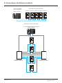
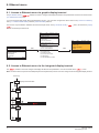
&RQQHFWLQJWRWKH(WKHUQHWQHWZRUN
PLC with embedded
RSTP management
(M340 + NOC401)
Redundant ring topology with RSTP
ATV61/71 ATV61/71 ATV61/71 ATV61/71 ATV61/71
Redundant star topology with RSTP
PLC with embedded RSTP management
(M340 + NOC401)
ATV61/71
ATV61/71
ATV61/71
Ethernet switch
with RSTP managment
Ethernet switch
with RSTP managment
ATV61/71
HRB10064 02/2013
13
efesotomasyon.com
(WKHUQHWPHQX
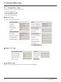
$FFHVVWR(WKHUQHWPHQXYLDJUDSKLFGLVSOD\WHUPLQDO
The [ETHERNET RSTP] (EtHrS) submenu is used to configure and display the Ethernet card parameters and can be accessed via the
[1.9 COMMUNICATION] menu.
If you are using the FDR (Faulty Device Replacement) function, you must also configure the device name in the [7 DISPLAY CONFIG.]
menu, [7.1 USER PARAMETERS] submenu, [DEVICE NAME] submenu.
This menu is only accessible in standard, advanced and expert mode: In the [2 ACCESS LEVEL] (LAC-) menu, set the level to [expert]
(EPr).
Can be accessed by the other level.
RDY
RDY
NET +0.00 Hz
MAIN MENU
1 DRIVE MENU
2 ACCESS LEVEL
3 OPEN / SAVE AS
4 PASSWORD
5 LANGUAGE
Code
0A
ENT
Quick
NET +0.00 Hz
0A
1 DRIVE MENU
1.1 SIMPLY START
1.2 MONITORING
1.3 SETTINGS
1.4 MOTOR CONTROL
1.5 INPUTS/OUTPUTS CFG
Code
<<
>>
Quick
1.6 COMMAND
1.7 APPLICATION FUNCT.
1.8 FAULT MANAGEMENT
1.9 COMMUNICATION
1.10 DIAGNOSTICS
1.11 IDENTIFICATION
1.12 FACTORY SETTINGS
1.13 USER MENU
1.14 PROGRAMMABLE CARD
RUN
ENT
NET
+50.00 Hz 80A
1.9 COMMUNICATION
COM. SCANNER OUTPUT
MODBUS HMI
MODBUS NETWORK
CANopen
ETHERNET RSTP
Code
<<
>>
Quick
$FFHVVWR(WKHUQHWPHQXYLDWKHLQWHJUDWHGGLVSOD\WHUPLQDO
The (EtH-) submenu is used to configure and display the Ethernet card parameters. It can be accessed via the (COM-) menu.
1RWH The device name required for the FDR (Faulty Device Replacement) function cannot be configured via the integrated display terminal.
Power-up
XXX
Displays the drive state
ENT
ESC
SIM-
ESC
FLtENT
ESC
CONESC
EtH-
ESC
FCS-
ESC
LAC-
14
HRB10064 02/2013
efesotomasyon.com
(WKHUQHWPHQX
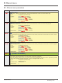
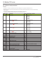
(WKHUQHWPHQXSDUDPHWHUV
&RGH
'HVFULSWLRQ
M>5DWH6HWWLQJ@
This field is used to set the transmission speed and the transmission mode of the card for the left port.
Type:
Configuration (read and write)
[Auto]
(AUtO): Autodetect
Possible
[10 Mbps full] (10F): 10 Mbps
values:
[10 Mbps half] (10H): 10 Mbps
[100 Mbps full] (100F): 100 Mbps
[100 Mbps half] (100H): 100 Mbps
Default value:
[Auto] (AUtO)
(rdS)
M>5DWH6HWWLQJ5LJKW@
This field is used to set the transmission speed and the transmission mode of the card for the right port.
Type:
Configuration (read and write)
[Auto] (AUtO): Autodetect
Possible
[10 Mbps full] (10F): 10 Mbps
values:
[10 Mbps half] (10H): 10 Mbps
[100 Mbps full] (100F): 100 Mbps
[100 Mbps half] (100H): 100 Mbps
Default value:
[Auto] (AUtO)
(rdSr)
M>$FWXDO5DWH@
This field displays the baud rate and the transmission mode currently used by the communication card for the left port.
Type:
Configuration (read only)
[Auto] (AUtO): Autodetect
Possible
[10 Mbps full] (10F): 10 Mbps
values:
[10 Mbps half] (10H): 10 Mbps
[100 Mbps full] (100F): 100 Mbps
[100 Mbps half] (100H): 100 Mbps
Default value:
[Auto] (AUtO)
(Ard)
M>$FWXDO5DWH5LJKW@
This field displays the baud rate and the transmission mode currently used by the communication card for the right port.
Type:
Configuration (read only)
[Auto] (AUtO): Autodetect
Possible
[10 Mbps full] (10F): 10 Mbps
values:
[10 Mbps half] (10H): 10 Mbps
[100 Mbps full] (100F): 100 Mbps
[100 Mbps half] (100H): 100 Mbps
Default value:
[Auto] (AUtO)
(Ardr)
(PAn-)
b >'(9,&(1$0(@
Device name used by FDR service.
The device name is required if the card uses DHCP to obtain its IP Adressess.
Use the navigation selector button to increment the character (alphabetical order) and << and >> (F2 and F3) to switch
to the next or previous character respectively. Use F1 to change to ABC, abc, 123.
Type:
Possible values:
Default value:
Configuration (read and write)
Display (read-only)
16 characters.
[-]
HRB10064 02/2013
15
efesotomasyon.com
(WKHUQHWPHQX
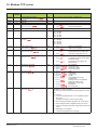
&RGH
(EtHM)
'HVFULSWLRQ
M>(WKHUQHW3URWRFRO@
Use this parameter to select the protocol.
Type:
Configuration (read and write)
[ModbusTCP] (MbtP) : ModbusTCP
Possible
[EthernetIP] (EtIP) : EtheNet/IP
values:
Default value:
(IPM)
(IPC-)
(IPC1)
(IPC2)
(IPC3)
(IPC4)
(IPM-)
(IPM1)
(IPM2)
(IPM3)
(IPM4)
(IPG-)
(IPG1)
(IPG2)
(IPG3)
(IPG4)
16
[ModbusTCP] (MbtP)
M>,3PRGH@
Use this parameter to select the IP address assignment method.
Type:
Configuration (read and write)
[Fixed] (MAnU): Manual setup of a fixed IP address
Possible
[BOOTP] (bOOt): BOOTP
values:
[DHCP] (dHCP) : DHCP
Default value:
[DHCP] (dHCP)
b>,3FDUG@
M>@139160069241
(WKHUQHWFDUG,3DGGUHVV
Type:
Configuration (read and write)
Display (read-only) if the address has been supplied by a BOOTP or DHCP server
Possible
• 0 to 255 for each of fields IPC1, IPC2, IPC3 and IPC4.
values:
• If IPM [IP mode] is not set to [Fixed] (MAnU) the Ethernet card waits for an IP address from a
BOOTP or DHCP server.
1RWH After dynamic addressing by a BOOTP or DHCP server, the current value is replaced by the
address supplied.
Default value:
[0.0.0.0] (0) (0) (0) (0)
b>,30DVN@
M>@2552552540
6XEQHWPDVN
Type:
Configuration (read and write)
Display (read-only) if the address has been supplied by a BOOTP or DHCP server
Possible
• 0 to 255 for each of fields IPM1, IPM2, IPM3 and IPM4.
values:
• If IPM [IP mode] is not set to [Fixed] (MAnU) the Ethernet card waits for a mask from a BOOTP
or DHCP server.
1RWH After dynamic addressing by a BOOTP or DHCP server, the current value is replaced by the
address supplied.
Default value:
[0.0.0.0] (0) (0) (0) (0)
b>,3*DWH@
M>@0000
*DWHZD\,3DGGUHVV
Type:
Configuration (read and write)
Display (read-only) if the address has been supplied by a BOOTP or DHCP server
Possible
• 0 to 255 for each of fields IPG1, IPG2, IPG3 and IPG4.
values:
• If IPM [IP mode] is not set to [Fixed] (MAnU) the Ethernet card waits for a gate from a BOOTP
or DHCP server.
1RWH After dynamic addressing by a BOOTP or DHCP server, the current value is replaced by the
address supplied.
Default value:
[0.0.0.0] (0) (0) (0) (0)
HRB10064 02/2013
efesotomasyon.com
(WKHUQHWPHQX
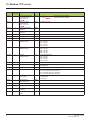
&RGH
(IPP-)
'HVFULSWLRQ
b>,30DVWHU@
M>@0000
(IPP1)
(IPP2)
(IPP3)
(IPP4)
(IPF-)
IP address of the device that retains control
Type:
Configuration (read and write)
Possible
• 0 to 255 for each of fields IPP1, IPP2, IPP3 and IPP4.
values:
• If the value is [0.0.0.0] (0) (0) (0) (0), writing of the control word (CMd) is accepted
by the Ethernet card regardless of which device has sent it.
• If the value is other than [0.0.0.0] (0) (0) (0) (0) only the device which has the IP address
[IP Master] is authorized to write the control word (CMd).
1RWH This configuration also affects the type of communication monitoring.
Default value:
[0.0.0.0] (0) (0) (0) (0)
b>,3)'5@
(IPF1)
(IPF2)
(IPF3)
(IPF4)
(E E)
M>@0000
IP address of the FDR server
Type:
Display (read-only)
Possible
• 0 to 255 for each of fields IPF1, IPF2, IPF3 and IPF4.
values:
• If the value is [0.0.0.0] (0) (0) (0) (0), there is no server.
Default value:
[0.0.0.0] (0) (0) (0) (0)
M>6HUYLYHV@
(FdrU)
Enables web server and e-mail server. This parameter is significant at the bit level.
Bit 0 and bit 1, other bits are reserved
Type:
Configuration (read and write)
Possible
• [0] (0): Web Server and Email functions are disabled.
values:
• [1] (1): Web Server actived.
• [2] (2): Email function activated.
• [3] (3): Web server and Email functions are activated.
Default value:
[3] (3)
M>)'5YDOLGDWLRQ@
(FdrA)
Enable FDR service
Type:
Configuration (read and write)
Possible
• Off = [No] (nO): FDR service disabled.
values:
• On = [Yes] (YES): FDR service enabled.
Default value:
On = [Yes] (YES)
M>)'5$FWLRQ@
FDR service command
Type:
Command (read and write)
Possible
• [IDLE] (IdLE): No command.
values:
• [SAVE] (SAUE): Command: save.
• [REST] (rESt): Command: Restore.
• [DEL] (dEL): Command: delete.
The command remains displayed during the action then reverts to the value [IDLE] (IdLE).
Default value:
[IDLE] (IdLE)
HRB10064 02/2013
17
efesotomasyon.com
(WKHUQHWPHQX
&RGH
'HVFULSWLRQ
(FdrS)
M>)'5DXWRVDYH@
(Fdrt)
Enable periodic saving of the FDR service
Type:
Configuration (read and write)
Possible
• Off = [No] (nO): Automatic saving disabled.
values:
• Yes = [Yes] (YES): Automatic saving enabled.
Default value:
Off = [No] (nO)
M>)'5WDXWRVDYH@
(FdrE)
Interval for periodic saving of the FDR service
Type:
Configuration (read and write)
Possible
• [2] (2) to [9999] (9999): 2 min to 9999 min.
values:
Default value:
[2] (2)
M>)'5VWDWH@
(FdrF)
FDR service state
Type:
Display (read-only)
Possible
• [IDLE] (IdLE): “Idle”.
values:
• [INIT] (INIt): Initialization.
• [CONF] (CONF): Configuration.
• [RDY] (rdY): Ready.
• [GET] (GEt): Restore the current configuration.
• [SET] (SEt): Save the current configuration.
• [APP] (APP): Write the FDR server configuration to the drive.
• [OPE] (OPE): Operational.
• [UCFG] (UCFG): Not configured.
Default value:
[IDLE] (IdLE)
M>)'5ILOHHUURU@
Enable FDR error management process
Type:
Configuration (read and write)
Possible
In the event of a problem with the FDR file (missing or invalid):
values:
• Off = [No] (nO): The Ethernet card does not trigger an Ethernet error(network management).
• On = [Yes] (YES): The Ethernet card triggers a network management error.
Default value:
On = [Yes] (YES)
(LCFG)
M>(WKHUQHWORFDOFRQI@
(IOSA)
Selection of local or server configuration
Type:
Configuration (read and write)
Possible
• Off = [No] (nO): The drive configuration is downloaded from an FDR server.
values:
• On = [Yes] (YES): The drive configuration is local and saved in a FDR server.
Default value:
Off = [No] (nO)
M>(WK,2VFDQDFW@
(tOUt)
IO scanner activation
Type:
Display (read)
Possible
• Off = [No] (nO): IO scanning disabled
values:
• On = [Yes] (YES): IO scanning enabled
Default value:
Off = [No] (nO)
M>(WKHUQHW7LPHRXW@
Ethernet timeout
Type:
Possible
values:
Default value:
18
Configuration (read and write)
• [0] (0.0) : Function deactivated
• [0.5] (0.5) to [60] (60.0)
[5] (5.0)
HRB10064 02/2013
efesotomasyon.com
(WKHUQHWPHQX
&RGH
'HVFULSWLRQ
(FdrS)
M>)'5DXWRVDYH@
(Fdrd)
Enable periodic saving of the FDR service
Type:
Configuration (read and write)
Possible
• Off = [No] (nO): Automatic saving disabled.
values:
• Yes = [Yes] (YES): Automatic saving enabled.
Default value:
Off = [No] (nO)
M>)'5)DXOW@
FDR service error code
Type:
Display (read-only)
Possible
• [0] (0): No fault.
values:
• [2] (2): The FDR configuration file is not compatible with the drive type
(example: the drive is not the same rating as that defined in the FDR file).
• [3] (3): Error reading the FDR configuration file on the server.
• [4] (4): Error writing the FDR configuration file to the server.
• [7] (7): Time-out for receipt of the FDR configuration file from the server.
• [9] (9): Duplication of IP address.
• [12] (12): The FDR configuration file is missing.
Default value:
[0] (0)
(MAC)
M>0$&#@
MAC address display (This parameter is not visible with integrated display).
Type:
Configuration (read only)
Default value:
[00-80-F4-XX-XX-XX]
HRB10064 02/2013
19
efesotomasyon.com
&RQILJXUDWLRQ
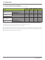
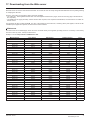
/LVWRIIXQFWLRQVWREHFRQILJXUHG
The table below gives the list of configuration functions and how they can be accessed:
)XQFWLRQV
Entering the IP addresses
Entering the device name
FDR
Configuration (time delay, etc.)
(Faulty Device Replacement)
Commands (save, etc.)
Enable IO Scanner
IO Scanning
Configuring the IO Scanner variables
Reserving control (IP master)
Communication monitoring
Changing the “username”
Security of access
Changing the “HTTP password”
to the standard Web server
Changing the “Write password”
Rapid Spanning Tree Protocol Enable RSTP function
(RSTP)
Configuring the RSTP parameters
*UDSKLF
GLVSOD\
WHUPLQDO
p
p
p
p
p
,QWHJUDWHG
GLVSOD\
WHUPLQDO
p
p
p
p
p
p
p
p
3&6RIWZDUH
VRIWZDUH
ZRUNVKRS
p
p
p
6WDQGDUG
:HE
VHUYHU
p
p
p
p
p
p
p
p
p
p
p
p
p
p
p
p
Configuration using the drive graphic display terminal or the integrated display terminal is explained in the “Configuration” section.
Configuration using the standard Web server is explained in the “Standard Web server” section.
For configuration using the PC-Software workshop, refer to the online help.
1RWH The Ethernet card saves its configuration (IP address, mask, gateway, etc.) to the EEPROM each time the configuration is modified.
1RWH For performance reasons, we do not recommend using the drive communication scanner. It is better to use the Ethernet IO Scanner.
1RWH Configuration must be performed with the motor stopped.
20
HRB10064 02/2013
efesotomasyon.com
&RQILJXUDWLRQ
'HWDLORIWKHFRQILJXULQJSDUDPHWHUV
b,3DGGUHVV
$VVLJQLQJ,3DGGUHVVHV
3 IP parameters shall be configured.
• The drive IP address (Mandatory)
• The subnet mask (Mandatory)
• The gateway IP address (Optional - for E-Mail service).
These IP addresses can be entered directly:
• Using the integrated display terminal.
• Using the graphic display terminal.
• Or using the PC-Software workshop.
They can be provided by:
• A BOOTP server (correspondence between the MAC address and the IP addresses).
• Or a DHCP server (correspondence between Device Name [DEVICE NAME] and the IP addresses).
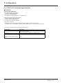
The address is assigned according to the IPmode parameter:
,S0RGHYDOXH
IP mode = 0
IP mode = 1
IP mode = 2
&RPPHQWV
The card uses the address defined in
IPC1, IPC2, IPC3, IPC4
The card receives its address from a BOOTP server
The card receives its address from a DHCP server
And Device name contains a valid
name.
HRB10064 02/2013
21
efesotomasyon.com
&RQILJXUDWLRQ
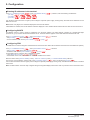
b(QWHULQJ,3DGGUHVVHVLQWKHWHUPLQDO
In the [1.9 - COMMUNICATION] (COM-) menu, [ETHERNET RSTP] (EtH-) submenu, enter the following IP addresses:
- [IP card] (IPC1) (IPC2) (IPC3) (IPC4).
- [IP Mask] (IPM1) (IPM2) (IPM3) (IPM4).
- [IP Gate] (IPG1) (IPG2) (IPG3) (IPG4).
Turn the drive off and then back on again (control voltage if a separate power supply is being used), otherwise the IP addresses are not
taken into account.
1RWH Before entry begins, the IP address displayed is the active IP address.
If this address is modified, the new IP address entered is displayed. This IP address will be effective the next time the drive is turned on.
b&RQILJXULQJ%2273
The BOOTP service is used to assign IP addresses from the MAC address. The MAC address consisting of 6 hexadecimal digits
(00-80-F4-xx-yy-zz) must be entered in the BOOTP server. The MAC address appears on the label attached to the Ethernet card.
In the [1.9 COMMUNICATION] (COM-) menu, [ETHERNET RSTP] (EtH-) submenu:
• Set [IP Mode] (IpM) at the value [BOOTP] (bOOtP)
• Do not enable the FDR service: [FDR validation] (FdrU) = [No] (nO).
b&RQILJXULQJ)'5
The FDR service is used to assign the IP addresses from the device name that must be entered in the drive and in the FDR server (DHCP).
In the [1.9 COMMUNICATION] (COM-) menu, [ETHERNET RSTP] (EtH-) submenu:
• Set [IP Mode] (IpM) at the value [DHCP] (dHCP).
• Enable the FDR service: [FDR validation] (FdrU) = [Yes] (YES).
For the FDR function, select the drive configuration as either:
• Local: [Ethernet local conf] (LCFG) = [Yes] (YES).
• Downloaded. In this case, it is essential to consult the “FDR Service” section.
Enter the device name, [DEVICE NAME], in the [7. DISPLAY CONFIG.] menu, [7.1 USER PARAMETERS] submenu.
This menu is only accessible in expert mode: In the [2 ACCESS LEVEL] (LAC-) menu, set the level to [expert] (EPr).
Turn the drive off and then back on again (control voltage if a separate power supply is being used), otherwise the device name is not taken
into account.
1RWH The FDR function cannot be fully configured using the integrated display terminal as it does not provide access to the device name.
22
HRB10064 02/2013
efesotomasyon.com
&RQILJXUDWLRQ
5HVHUYLQJFRQWURO
It is strongly recommended that control should be reserved for a single master device.
• If control has been reserved:
Only the control word (CMd) written by the master with control will be accepted via IO Scanning or via Modbus TCP messaging.
2 TCP connections are reserved for this device. In this way, you avoid other TCP clients using all the available connections (8 maximum)
and the control master therefore no longer being able to access the drive Modbus TCP server. Other parameters written from other IP
addresses are accepted (for example, adjustments or writing a setpoint).
When control has been reserved and another device attempts to write the control word (CMd):
- via IO Scanning: The Modbus TCP connection for this client is immediately reinitialized.
- via Modbus TCP messaging: Control is denied.
• If control has not been reserved ([IP Master] = [0.0.0.0] (0) (0) (0) (0)), control can come from any IP address.
• If control were not to be reserved for a master device (for example a PLC):
- Any other Modbus TCP Ethernet client could send unwanted commands.
- Other clients could use the 8 available TCP connections and prevent the master from having control.
To configure this reservation, enter an IP address other than [0.0.0.0] (0) (0) (0) (0) in the [1.9 COMMUNICATION] (COM-) menu,
[ETHERNET RSTP] (EtH-) submenu, [IP Master] submenu.
:$51,1*
81(;3(&7('(48,30(1723(5$7,21'8(72,30$67(512763(&,),('
Use the [IP MASTER] (IPP) menu option to configure a network master device. If a valid IP address for a master device is not specified
using this option, other Ethernet clients can saturate the TCP connections or send incorrect commands.
)DLOXUHWRIROORZWKLVLQVWUXFWLRQFDQUHVXOWLQGHDWKVHULRXVLQMXU\RUHTXLSPHQWGDPDJH
&RQILJXULQJ,26FDQQLQJ
Refer to the “IO Scanning Service” section.
The drive IO Scanning service can be enabled or disabled in the [1.9 - COMMUNICATION] (COM-) menu, [ETHERNET RSTP] (EtH-)
submenu via parameter [Eth IO scan act] (IOSA).
It is not possible to modify the assignment of the IO Scanning periodic variables using the display terminal (integrated or graphic).
To configure IO Scanning, use the standard Web server or the PC-Software workshop.
HRB10064 02/2013
23
efesotomasyon.com
&RQILJXUDWLRQ
&RQILJXULQJWKHFRQWURO
Numerous configurations are possible. For more information, refer to the Programming Manual and the Communication parameters
Manual.
The following configurations are just some of the possibilities available.
b&RQWUROYLD(WKHUQHWLQ,2SURILOH
The command and setpoint come from Ethernet.
The command is in I/O profile.
Configure the following parameters:
3DUDPHWHU
Profile
Setpoint 1 configuration
Command 1 configuration
9DOXH
I/O profile
Network card
Network card
&RPPHQW
The run command is simply obtained by bit 0 of the control word.
The setpoint comes from Ethernet.
The command comes from Ethernet.
Configuration via the graphic display terminal or the integrated display terminal:
0HQX
[1.6 - COMMAND] (CtL-)
3DUDPHWHU
[Profile] (CHCF)
[Ref.1 channel] (Fr1)
[Cmd channel 1] (Cd1)
9DOXH
[I/O profile] (IO)
[Com. card] (nEt)
[Com. opt card] (nEt)
b&RQWUROYLD(WKHUQHWRUWKHWHUPLQDOVLQ,2SURILOH
Both the command and setpoint come from Ethernet or the terminals. Input LI5 at the terminals is used to switch between Ethernet
and the terminals.
The command is in I/O profile.
Configure the following parameters:
3DUDPHWHU
Profile
Setpoint 1 configuration
Setpoint 1B configuration
Setpoint switching
Command 1 configuration
Command 2 configuration
Command switching
9DOXH
I/O profile
Network card
Analog input 1 on the terminals
Input LI5
Network card
Terminals
Input LI5
&RPPHQW
The run command is simply obtained by bit 0 of the control word.
Setpoint 1 comes from Ethernet.
Setpoint 1B comes from input AI1 on the terminals.
Input LI5 switches the setpoint (1l1B).
Command 1 comes from Ethernet.
Command 2 comes from the terminals.
Input LI5 switches the command.
1RWH Setpoint 1B is connected to the functions (summing, PID, etc.), which remain active, even after switching.
Configuration via the graphic display terminal or the integrated display terminal:
0HQX
[1.6 - COMMAND] (CtL-)
[1.7 APPLICATION FUNCT.] (FUn-)
[REFERENCE SWITCH.]
24
3DUDPHWHU
[Profile] (CHCF)
[Ref.1 channel] (Fr1)
[Cmd channel 1] (Cd1)
[Cmd channel 2] (Cd2)
[Cmd switching] (CCS)
[Ref.1B channel] (Fr1b)
[Ref 1B switching] (rCb)
9DOXH
[I/O profile] (IO)
[Com. card] (nEt)
[Com. card] (nEt)
[Terminals] (tEr)
[LI5] (LI5)
[Ref. AI1] (AI1)
[LI5] (LI5)
HRB10064 02/2013
efesotomasyon.com
&RQILJXUDWLRQ
b&RQWUROYLD(WKHUQHWLQ'ULYHFRPSURILOH
The command and setpoint come from Ethernet.
The command is in Drivecom profile.
Configure the following parameters:
3DUDPHWHU
Profile
Setpoint 1 configuration
9DOXH
Drivecom profile not
separate
Network card
&RPPHQW
The run commands are in Drivecom profile, the command and the setpoint
come from the same channel.
The command comes from Ethernet.
Configuration via the graphic display terminal or the integrated display terminal:
0HQX
[1.6 - COMMAND] (CtL-)
3DUDPHWHU
[Profile] (CHCF)
[Ref.1 channel] (Fr1)
9DOXH
[Not separ.] (SIM) (factory setting)
[Com. card] (nEt)
b&RQWUROYLD(WKHUQHWRUWKHWHUPLQDOVLQ'ULYHFRPSURILOH
Both the command and setpoint come from Ethernet or the terminals. Input LI5 at the terminals is used to switch between Ethernet
and the terminals.
The command is in Drivecom profile.
Configure the following parameters:
3DUDPHWHU
Profile
9DOXH
Drivecom profile not separate
Setpoint 1 configuration
Setpoint 2 configuration
Setpoint switching
Network card
Analog input 1 on the terminals
Input LI5
&RPPHQW
The run commands are in Drivecom profile, the command and the
setpoint come from the same channel.
Setpoint 1 comes from Ethernet.
Setpoint 2 comes from input AI1 on the terminals.
Input LI5 switches the setpoint (1l2) and the command.
1RWH Setpoint 2 is directly connected to the drive setpoint limit. If switching is performed, the functions that affect the setpoint (summing,
PID, etc.) are disabled.
Configuration via the graphic display terminal or the integrated display terminal:
0HQX
[1.6 - COMMAND] (CtL-)
3DUDPHWHU
[Profile] (CHCF)
[Ref.1 channel] (Fr1)
[Ref.2 chan] (Fr2)
[Ref. 2 switching] (rFC)
9DOXH
[Not separ.] (SIM)
[Com. card] (nEt)
[Ref. AI1] (AI1)
[LI5] (LI5)
HRB10064 02/2013
25
efesotomasyon.com
&RQILJXUDWLRQ
b&RPPDQGLQ'ULYHFRPSURILOHYLD(WKHUQHWDQGVHWSRLQWVZLWFKLQJDWWKHWHUPLQDOV
The command comes from Ethernet.
The setpoint comes either from Ethernet or from the terminals. Input LI5 at the terminals is used to switch the setpoint between Ethernet
and the terminals.
The command is in Drivecom profile.
Configure the following parameters:
3DUDPHWHU
Profile
9DOXH
Drivecom profile separate
Setpoint 1 configuration
Setpoint 1B configuration
Setpoint switching
Command 1 configuration
Command switching
Network card
Analog input 1 on the terminals
Input LI5
Network card
Channel 1
&RPPHQW
The run commands are in Drivecom profile, the command and the
setpoint can come from different channels.
Setpoint 1 comes from Ethernet.
Setpoint 1B comes from input AI1 on the terminals.
Input LI5 switches the setpoint (1l1B).
Command 1 comes from Ethernet.
Channel 1 is the command channel.
1RWH Setpoint 1B is connected to the functions (summing, PID, etc.), which remain active, even after switching.
Configuration via the graphic display terminal or the integrated display terminal:
0HQX
[1.6 - COMMAND] (CtL-)
[1.7 APPLICATION FUNCT.] (FUn-)
[REFERENCE SWITCH.]
26
3DUDPHWHU
[Profile] (CHCF)
[Ref.1 channel] (Fr1)
[Cmd channel 1] (Cd1)
[Cmd switching] (CCS)
[Ref.1B channel] (Fr1b)
[Ref 1B switching] (rCb)
9DOXH
[Separate] (SEP)
[Com. card] (nEt)
[Com. card] (nEt)
[Ch1 active] (Cd1)
[Ref. AI1] (AI1)
[LI5] (LI5)
HRB10064 02/2013
efesotomasyon.com
&RQILJXUDWLRQ
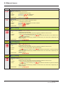
&RQILJXULQJWKHIDXOWPDQDJHPHQW
b&RPPXQLFDWLRQPRQLWRULQJ
The Ethernet card can detect 2 types of fault:
- Network management faults (server missing, duplication of IP address, etc.).
- Communication faults (time out on the master traffic, etc.).
The associated information is:
(WKHUQHWIDXOWW\SH
1HWZRUNPDQDJHPHQW
$VVRFLDWHGGULYHIDXOW
&RQILJXULQJWKH
FRPPXQLFDWLRQIDXOW
&RQILJXULQJWKHGULYH¶V
UHVSRQVH
Code:
[External fault com.] (EPF2)
Parameter:
[FDR File Error] (FdrF)
Menu:
[1.9 COMMUNICATION] (COM-)
Submenu:
[ETHERNET RSTP] (EtH-)
Parameter:
[External fault mgt] (EPL)
Menu:
[1.8 FAULT MANAGEMENT] (FLt-)
Submenu:
[EXTERNAL FAULT] (EtF-)
&RPPXQLFDWLRQ
Code:
[Com. network] (CnF)
Parameter:
[Ethernet TimeOut] (tOUt)
Menu:
[1.9 COMMUNICATION] (COM-)
Submenu:
[ETHERNET RSTP] (EtH-)
Parameter:
[COM. fault mgt] (CLL)
Menu:
[1.8 FAULT MANAGEMENT] (FLt-)
Submenu:
[COM. FAULT MANAGEMENT] (CLL-)
b1HWZRUNPDQDJHPHQWIDXOW
The IP address duplication management fault cannot be configured.
If the FDR (Faulty Device Replacement) service has been configured, the FDR fault can be disabled via the [FDR File Error] (FdrF)
parameter, which can be accessed via the [1.9 COMMUNICATION] (COM-) menu, [ETHERNET RSTP] (EtH-) submenu.
In factory settings mode, a network management fault will trigger a resettable drive fault [External fault com.] (EPF2) and initiate
a freewheel stop.
b&RPPXQLFDWLRQIDXOW
Monitoring begins when the first control word is received.
Even if the command channel is not the network, a write access on the CMD word is necessary to activate the monitoring of the network.
• If control has been reserved:
A communication fault is triggered if the Ethernet card does not receive a Modbus TCP request within a predefined period
of time (time out).
Any type of Modbus request from the master device [IP Master] is taken into account (write operation, read operation, etc.).
• If control has not been reserved:
A communication fault is triggered if the Ethernet card does not receive a control word write request (CMd) within a predefined
period of time (time out).
Receipt of the command (CMd) is taken into account regardless of the sender’s IP address.
The “time out” can be set to between 0.5 and 60 s via the graphic display terminal or integrated display terminal in the
[1.9 COMMUNICATION] (COM-) menu, [ETHERNET RSTP] (EtH-) submenu via the [Ethernet Timeout] (tOUt) parameter. The
default value is 5 s.
In factory settings mode, if Ethernet is involved in the command or setpoint, a communication fault will trigger a resettable drive fault
[Com. network] (CnF) and initiate a freewheel stop.
HRB10064 02/2013
27
efesotomasyon.com
&RQILJXUDWLRQ
b'ULYHUHVSRQVH
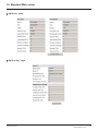
The drive response to an Ethernet fault can be configured via the graphic display terminal or the integrated display terminal,
from the [1.8 FAULT MANAGEMENT] (FLt-) menu:
RDY
For communication faults
in the [COM. FAULT MANAGEMENT] (CLL-) submenu
via parameter [COM. fault mgt] (CLL)
NET
+0.00Hz
0A
COM. FAULT MANAGEMENT
Network fault mgt
:
Freewheel
CANopen fault mgt
:
Freewheel
Modbus fault mgt
:
Freewheel
Code
Quick
RDY
For network management faults
in the [EXTERNAL FAULT] (EtF-) submenu
via the [External fault mgt] (EPL) parameter
NET
+0.00Hz
0A
EXTERNAL FAULT
External fault mgt
:
Freewheel
Code
Quick
The values of parameters: [COM. fault mgt] (CLL) that will trigger a drive fault [Com. network] (CnF)
and [External fault mgt] (EPL) that will trigger a drive fault [External fault com.] (EPF2) are:
[Freewheel] (YES): Freewheel stop (factory setting).
[Ramp stop] (rMP): Stop on ramp.
[Fast stop] (FSt): Fast stop.
[DC injection] (dCI): DC injection stop.
The values of parameters [COM. fault mgt] (CLL) and [External fault management] (EPL) which will not trigger a drive fault are:
[Ignore] (nO): Fault ignored.
[Per STT] (Stt): Stop according to configuration of [Stop type] (Stt).
[fallback spd] (LFF): Change to fallback speed, maintained as long as the fault persists and the run command has not been removed.
[Spd maint.] (rLS): The drive maintains the speed at the time the fault occurred, as long as the fault persists and the run command has
not been removed.
The fallback speed can be configured in the [1.8 - FAULT MANAGEMENT] (FLt-) menu via the [Fallback speed] (LLF) parameter.
28
HRB10064 02/2013
efesotomasyon.com
&RQILJXUDWLRQ
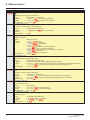
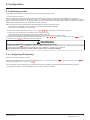
&RQILJXULQJPRQLWRUHGSDUDPHWHUV
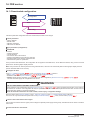
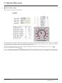
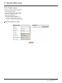
It is possible to select up to 4 parameters to display their values in the [1.2 - MONITORING] menu on the graphic display terminal.
The selection is made via the [6 - MONITORING CONFIG.] menu, [6.3 - COM. MAP CONFIG.] submenu.
Each parameter in the range [Address 1 select.] … [Address 4 select.]
is used to select the parameter logic address. Select an address of zero
to disable the function.
In the example given here, the monitored words are:
• Parameter 1 = Motor current (LCR): logic address 3204;
signed decimal format.
• Parameter 2 = Motor torque (OTR): logic address 3205;
signed decimal format.
• Parameter 3 = Last fault occurred (LFT): logic address 7121;
hexadecimal format.
• Disabled parameter: address 0; default format: hexadecimal format.
RDY
NET
+0.00Hz
0A
6.3 COM. MAP CONFIG.
Word 1 add. select.
:
3204
Format word 1
:
Signed
Word 2 add. select.
:
3205
Format word 2
:
Signed
Word 3 add. select.
:
7121
Code
Quick
Format word 33
:
Hex
Word 4 add. select.
Format word 4
:
:
0
Hex
One of the three display formats below can be assigned to each monitored word:
)RUPDW
Hexadecimal
Signed decimal
Unsigned decimal
5DQJH
0000 … FFFF
-32,767 … 32,767
0 … 65,535
7HUPLQDOGLVSOD\
[Hex]
[Signed]
[Unsigned]
HRB10064 02/2013
29
efesotomasyon.com
'LDJQRVWLFV
6LJQDOOLQJ/('V
The VW3 A3320 Ethernet card features 5 LEDs, which are visible through the Altivar 61 / 71 cover.
1.1
1.2
1.3
1.4
1.5
2.1
2.2
2.3
2.4
2.5
3RUWDFWLYLW\
3RUWDFWLYLW\
/LQNVWDWXV
161HWZRUNVWDWXV
060RGXOHVWDWXV
The 2 first LEDS are respectively dedicated to each Ethernet port.
The third LED is relative to the IP level.
The 2 last LEDs are specific to the communication protocol.
/('
2.1
&RORUVWDWH
Off
Flashing Green/yellow
Green ON
Yellow ON
Green BLINK
Yellow BLINK
'HVFULSWLRQ
No link
Power up testing.
Link at 100 Mbps.
Link at 10 Mbps.
Activity at 100 Mbps.
Activity at 10 Mbps.
2.2
Off
Flashing Green/yellow
Green ON
Yellow ON
Green BLINK
Yellow BLINK
No link
Power up testing.
Link at 100 Mbps.
Link at 10 Mbps.
Activity at 100 Mbps.
Activity at 10 Mbps.
2.3
Off
Flashing Green/red
Green ON
Green flashing 3 times
Green flashing 4 times
Green flashing 5 times
Physical connections unplugged - No IP address obtained
Power up testing.
At least one port is connected and an IP address has been obtained.
All ports are unplugged, but the card has an IP address.
Error: Duplicated IP address (1)
The card is performing a BOOTP or DHCP sequence
2.4
"NS"
Off
Flashing Green/red
Green ON
Green flashing
Red Flashing
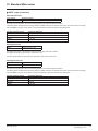
Red ON
The device does not have an IP address or powered off.
Power up testing.
The device has at least one established Modbus connection (even to the Message Router).
The device has not established Modbus connections, but has obtained an IP address.
The device has detected a recoverable fault
The device has detected an unrecoverable fault
2.5
"MS"
Off
Flashing Green/red
Green ON
Green flashing
Red flashing
Red ON
No power is supplied to the device
Power Up testing.
The device is operating correctly.
The device has not been configured.
The device has detected a recoverable minor fault.
The device has detected a non-recoverable major fault (1).
(1) In case of duplicate IP Address, the led 2.3 is green flashing 4 times, led 2.4 and 2.5 are solid red.
30
HRB10064 02/2013
efesotomasyon.com
'LDJQRVWLFV
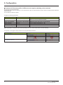
$YDLODEOHLQIRUPDWLRQ
In addition to the LEDs, the table below summarizes the diagnostic information available by various means.
)XQFWLRQV
*UDSKLFGLVSOD\
WHUPLQDO
,QWHJUDWHGGLVSOD\
WHUPLQDO
3&6RIWZDUH
ZRUNVKRS
6WDQGDUG
:HE VHUYHU
p
p
p
p
p
p
Control-signal diagnostics
• Control word
• Setpoint
• Active channel
• Etc.
Communication diagnostics
• Transmission counter
• Reception counter
• Collision counter
• Etc.
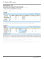
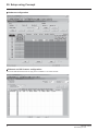
0RQLWRULQJWKHFRQWURO
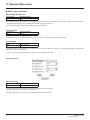
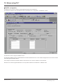
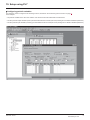
On the graphic display terminal only, the [1.2 - MONITORING] menu, [COMMUNICATION MAP] submenu can be used to display
control-signal diagnostic information between the drive and the Ethernet PLC:
Active command channel
Value of control word used
to send a command to the drive
(hexadecimal format)
Active setpoint channel
RUN
Value of frequency setpoint
(unit 0.1 Hz) used to control the drive
Value of status word
(hexadecimal format)
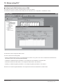
Values of the four monitored words selected by the user.
The address and display format of these parameters
can be configured in the [6 - MONITORING CONFIG.] menu,
[6.3 - COM. MAP CONFIG.] submenu
(see “Configuration” section on page 20).
The value of a monitored word is equal to “-----” if:
- Monitoring has not been activated
(address equal to W0)
- The parameter is protected
- The parameter is not known (e.g., W3200)
NET
+50.00 Hz
80A
COMMUNICATION MAP
Command Channel
:
Com. card
Cmd value
:
000FHex
Channel ref. active
:
Com. card
Frequency ref.
:
500.0Hz
Status word
:
8627Hex
Code
Quick
W3204
:
53
W3205
:
725
W7132
:
0000Hex
W0
:
-----Hex
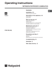
COM. SCANNER INPUT MAP
COM SCAN OUTPUT MAP
Communication scanner:
use not recommended for Ethernet
CMD. WORD IMAGE
FREQ. REF. WORD MAP
Control word from Ethernet
[COM. card cmd.] (CMd3)
Frequency setpoint from Ethernet
[Com. card ref.] (LFr3)
MODBUS NETWORK DIAG
MODBUS HMI DIAG
CANopen MAP
SCANNER CARD PROG.
HRB10064 02/2013
31
efesotomasyon.com
'LDJQRVWLFV
7URXEOHVKRRWLQJWKHFRPPXQLFDWLRQIDXOW
b&RPPXQLFDWLRQPRQLWRULQJ
Ethernet faults are indicated by the red FLT LED on the Ethernet card.
The Ethernet card can detect 2 types of fault:
- Network management faults (server missing, duplication of IP address, etc.).
- Communication faults (time out on the master traffic, etc.).
In factory settings mode, a network management fault will trigger a resettable drive fault [External fault com.] (EPF2) and initiate
a freewheel stop.
In factory settings mode, if Ethernet is involved in the command or setpoint, a communication fault will trigger a resettable drive fault
[Com. network] (CnF) and initiate a freewheel stop.
The drive’s response in the event of an Ethernet communication fault can be changed (see the Configuration section).
- Drive fault [Com. network] (CnF) or [External fault com.] (EPF2) (freewheel stop, stop on ramp, fast stop or DC
injection braking stop).
- No drive fault (stop, maintain, fallback).
The associated information is:
(WKHUQHWFRPPXQLFDWLRQIDXOWW\SH
1HWZRUNPDQDJHPHQW
&RPPXQLFDWLRQ
$VVRFLDWHGGULYHIDXOW
Code:
[External fault com.] (EPF2)
Code:
[Com. network] (CnF)
([WHQGHGIDXOWFRGH
[FDR fault] (Fdrd)
Menu:
[1.9 COMMUNICATION] (COM-)
Submenu:
[ETHERNET RSTP] (EtH-)
[Network fault] (CnF)
Menu:
[1.10 DIAGNOSTICS] (dGt-)
Submenu:
[MORE FAULT INFO] (AFI-)
Parameter [Network fault] (CnF) is used to obtain more detailed information about the origin of the last fault [Com. network] (CnF). It can
be accessed on the graphic display terminal only, in the [1.10 DIAGNOSTICS] (dGt-) menu, [MORE FAULT INFO] (AFI-) submenu.
9DOXH
'HVFULSWLRQRIWKHYDOXHVRIWKH>1HWZRUNIDXOW@&Q)SDUDPHWHU
0
No fault
1
Modbus TCP time out
10
Network overload
11
Loss of Ethernet carrier
The [FDR fault] (Fdrd) Ethernet fault parameter is used to obtain more detailed information about the origin of the last fault
[External fault com.] (EPF2). It can be accessed on the graphic display terminal only, in the [1.9 COMMUNICATION] (COM-) menu,
[ETHERNET RSTP] (EtH-) submenu.
9DOXH
'HVFULSWLRQRIWKHYDOXHVRIWKH>)'5IDXOW@)GUG(WKHUQHWIDXOWFRGHSDUDPHWHU
0
No fault.
2
The FDR configuration file is not compatible with the drive type (example: the drive is not the correct rating).
3
Error reading the FDR configuration file on the server.
4
Error writing the FDR configuration file to the server.
7
Time-out for receipt of the FDR configuration file from the server.
9
Duplication of IP address (1).
12
FDR configuration file missing.
203
Inconsistent hardware configuration
(1) The Ethernet card detects IP address duplication each time it connects to the network (power-up or connection to the network).
If the card detects that another device is using the same IP address as itself, it abandons the use of the IP address and triggers a fault
[External fault com.] (EPF2).
If a device with an IP address identical to that of the drive is connected to the network during operation, the drive does not detect a fault
(it is the new station that has to disconnect).
32
HRB10064 02/2013
efesotomasyon.com
'LDJQRVWLFV
7URXEOHVKRRWLQJWKHFDUGIDXOW
The [internal com. link] (ILF) fault appears when the following serious problems occur:
- Hardware fault on the Ethernet card.
- Dialog fault between the Ethernet card and the drive.
The drive’s response in the event of an [internal com. link] (ILF) fault cannot be configured, and the drive trips with a freewheel stop.
This fault cannot be reset.
Two diagnostic parameters are used to obtain more detailed information about the origin of the [internal com. link] (ILF) fault:
- [Internal link fault 1] (ILF1) if the fault has occurred on option card no. 1 (installed directly on the drive).
- [Internal link fault 2] (ILF2) if the fault has occurred on option card no. 2 (installed on option card no. 1).
The Ethernet card can be in position 1 or 2.
The [Internal link fault 1] (ILF1) and [Internal link fault 2] (ILF2) parameters can only be accessed on the graphic display terminal
in the [1.10 DIAGNOSTICS] (dGt-) menu, [MORE FAULT INFO] (AFI-) submenu.
9DOXH
'HVFULSWLRQRIWKHYDOXHVRIWKH[Internal link fault 1] (ILF1) and [Internal link fault 2] (ILF2) parameters
0
No fault
1
Loss of internal communication with the drive
3
Error in the EEPROM checksum
101
Unknown card
102
Exchange problem on the drive internal bus
103
Time out on the drive internal bus (500 ms)
HRB10064 02/2013
33
efesotomasyon.com
6RIWZDUHVHWXS
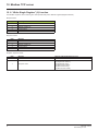
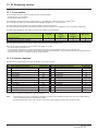
/LVWRIVHUYLFHVVXSSRUWHG
• Modbus TCP server, with the support of the “IO Scanning” periodic service.
• IP protocol (version 4).
• TCP and UDP protocol.
• HTTP server for configuring, adjusting and monitoring the drive.
• ICMP client for supporting certain IP services, such as the “ping” command.
• BOOTP client for assignment of an IP address by an address server.
• FTP protocol for file transfer.
• DHCP client for dynamic assignment of IP addresses by an address server.
• FDR service for replacement of a faulty device.
• SNMP protocol for network management.
• ARP protocol for detecting a competing IP address (IP address already in use).
• Rapid Spanning Tree Protocol RSTP.
7&3FRQQHFWLRQV
Number of simultaneous connections limited to 8 maximum (port 502).
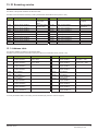
The table below gives the number of connections consumed for each service:
&OLHQW
Controller (PLC)
Web browser
6HUYLFH
IO Scanning
Modbus messaging
“Home” page
“Monitoring\Drive monitoring”
“Monitoring\Drive parameters”
“Monitoring\Drive chart”
“Diagnostics\Ethernet”
“Diagnostics\Modbus TCP”
“Diagnostics\EtherNET/IP”
“Diagnostics\RSTP port”
“Diagnostics\RSTP bridge”
"Setup\Network & protocol"
"Setup\ RSTP"
"Setup\Modbus TCP scanner"
"Setup\EtherNET/IP scanner"
"Setup\FDR agent"
"Setup\Email"
"Security\Monitor password"
"Security\Data write password"
"Security\Administrator password"
1XPEHURIFRQQHFWLRQV
1
1
0
2
1
1
1
1
1
1
1
1
1
1
1
1
1
0
0
0
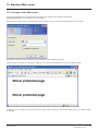
Example:
If the “Altivar Viewer” page is viewed in two different windows of a Web browser, on the same PC, four connections are consumed.
If the drive is controlled by a PLC, two connections are consumed by IO Scanning and Modbus messaging, so the total number
of connections consumed is then six.
Two connections are still available, since the maximum number of simultaneous connections is eight.
If control is reserved for a device ([IP Master] (IPP-) configured), 2 connections are reserved for this device, even if it is not present
on the network.
If the maximum number of connections has been exceeded, any new connection attempt will be rejected by the Ethernet card.
34
HRB10064 02/2013
efesotomasyon.com
0RGEXV7&3VHUYHU
0RGEXV7&3IUDPHV
Modbus TCP frames consist of a header and a Modbus request.
+HDGHUIRUPDW
%\WH
0
1
2
3
4
5
6
7
'HVFULSWLRQ
Transaction identifier
Protocol identifier
Length of data
&RPPHQWV
high order
low order
high order
low order
high order
low order
This identifier equals 0.
Number of bytes in the Modbus request +1. The frame length is less than 256
bytes, the value of the significant byte therefore equals 0.
Destination identifier (Unit ID)
Modbus request function code
The frame header returned by the Altivar 61/71 server is identical to that of the frame sent by the client.
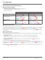
'ULYH0RGEXVVHUYHUV
The destination identifier (Unit ID) is used to access 4 drive Modbus TCP servers:
8QLW,'
0
251, AMOC
252, AMOA
255
0RGEXV7&3VHUYHU
Variable speed drive
Ethernet card
Controller Inside card
IO Scanner
$FFHVVLEOHSDUDPHWHUV
See the Altivar 61/71 Communication parameters Manual.
See the user manual “Ethernet card parameters” section.
2048 words (%MW0 to %MW2047).
See the "Modbus TCP Scanner" section.
HRB10064 02/2013
35
efesotomasyon.com
0RGEXV7&3VHUYHU
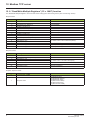
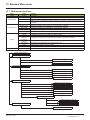
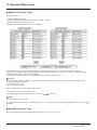
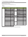
(WKHUQHWFDUGSDUDPHWHUV
&RPPHQWV
• Parameters on 2 words are double words (low order in address word n, high order in address word n+1).
• Parameters 60 019 to 60 043 and 60 066 to 60 068 can be accessed in both read and write mode. They can be reset using
a write operation.
• The current IP addresses (60006 to 60017) are the ones displayed on the terminal.
The EEPROM IP addresses (60075 to 60079) are the ones used by the card.
$GGUHVV 6L]H
'HVFULSWLRQ
LQZRUGV
60 000
6
MAC address
36
$FFHVV 3RVVLEOHYDOXHVFRPPHQWV
R
60 006
4
Current value of IP Address
[IP card] (IPC-)
R
60 010
4
Current value of Subnet mask
[IP Mask] (IPM-)
R
60 014
4
Current value of Gateway Address
[IP Gate] (IPG-)
R
60 018
1
Transmission speed
[Bit rate] (bdr)
R
60 019
60 021
60 022
60 023
60 024
60 026
60 027
60 028
60 029
60 030
60 031
60 032
60 034
60 036
60 037
60 039
60 041
60 042
60 043
60 044
2
1
1
1
2
1
1
1
1
1
1
2
2
1
2
2
1
1
1
1
OK transmission counter
Store-and-forward transmission counter
Late collision counter
Buffer (Tx) error counter
OK reception counter
CRC error counter
Frame error counter
Buffer (Rx) error counter
Collision counter
Multiple collision counter
OverRun counter
Sent Modbus TCP message counter
Received Modbus TCP message counter
Modbus TCP message error counter
Sent IO Scanning message counter
Received IO Scanning message counter
IO Scanning message error counter
Active traffic (msg/s)
Max. traffic (msg/s)
Number of active TCP connections
R/W
R/W
R/W
R/W
R/W
R/W
R/W
R/W
R/W
R/W
R/W
R/W
R/W
R/W
R/W
R/W
R/W
R/W
R/W
R
00-80-F4-xx-yy-zz
00: 60 000
80: 60 001
F4: 60 002
xx: 60 003
yy: 60 004
zz: 60 005
IPC1.IPC2.IPC3.IPC4
IPC1: 60 006
IPC2: 60 007
IPC3: 60 008
IPC4: 60 009
IPM1.IPM2.IPM3.IPM4
IPM1: 60 010
IPM2: 60 011
IPM3: 60 012
IPM4: 60 013
IPG1.IPG2.IPG3.IPG4
IPG1: 60 014
IPG2: 60 015
IPG3: 60 016
IPG4: 60 017
= 0: Speed not defined
= 10: 10 Mbps
= 100: 100 Mbps
IO Scanning messages not included
IO Scanning messages not included
IO Scanning messages not included
8 maximum
HRB10064 02/2013
efesotomasyon.com
0RGEXV7&3VHUYHU
$GGUHVV 6L]H
'HVFULSWLRQ
LQZRUGV
$FFHVV 3RVVLEOHYDOXHVFRPPHQWV
60 045
1
Communication monitoring
time out [Ethernet TimeOut] (tOUt)
R/W
Unit: 0.1 s; min. = 5 (0.5 s); max. = 600 (60.0 s)
60 046
1
Reserved
R
=2
60 047
1
Reserved
R
=0
60 048
1
Enable IO Scanner
[Eth IO scan act] (IOSA)
R/W
R
=0
[No] (nO)
: IO Scanning disabled.
=1
[Yes] (YES)
: IO Scanning enabled.
60 049
1
Reserved
60 050
4
IP address of Master [IP Master] (IPP-) R/W
60 054
4
IP address of DHCP-FDR server
[IP FDR] (IPF-)
R
IPF1.IPF2.IPF3.IPF4
IPF1 = 60 054
IPF2 = 60 055
IPF3 = 60 056
IPF4 = 60 057
60 058
1
Enable FDR service
[FDR validation] (FdrU)
R/W
0=
[No] (nO)
: FDR service disabled
1=
[Yes] (YES)
: FDR service enabled
60 059
1
Select local configuration
[Ethernet local conf] (LCFG)
R/W
0=
[No] (nO)
: The drive configuration is
downloaded from an FDR server
1=
[Yes] (YES)
: The drive configuration is local
60 060
1
Enable FDR error managment
[FDR File Error] (FdrF)
R/W
60 061
1
FDR service command
[FDR Action] (FdrA)
R/W
60 062
1
FDR service state
[FDR state] (FdrE)
R
=0
IPP1.IPP2.IPP3.IPP4
IPP1 = 60 050
IPP2 = 60 051
IPP3 = 60 052
IPP4 = 60 053
In the event of a problem with the FDR file (missing or invalid)
0=
[No] (nO)
: The Ethernet card does not trigger
an Ethernet fault
1=
[Yes] (YES)
: The Ethernet card triggers an
Ethernet fault
0=
20 =
21 =
22 =
[IDLE] (IdLE)
[SAVE] (SAUE)
[REST] (rESt)
[DEL] (dEL)
: No command
: Command: save
: Command: restore
: Command: delete
0=
1=
2=
3=
4=
[IDLE] (IdLE)
[INIT] (INIt)
[CONF] (CONF)
[RDY] (rDY)
[GET] (GEt)
5=
6=
7=
8=
60 063
1
Ethernet fault code
[FDR fault] (Fdrd)
R
: “Idle”
: Initialization
: Configuration
: Ready
: Downloading the current
configuration
: Saving the current configuration
[SET] (SEt)
: Writing the FDR server
[APP] (APP)
configuration to the drive
: Operational
[OPE] (OPE)
[UCFG] (UCFG) : Not configured
When an Ethernet fault is present, this parameter is used to
ascertain the cause of the fault.
The fault code remains saved after the disappearance of the
fault.
0 = No error
2 = The FDR configuration file is not compatible with the
drive type
(example: the drive is not the correct rating)
3 = Error reading the FDR configuration file on the server
4 = Error writing the FDR configuration file to the server
7 = Time out for receipt of the FDR configuration file from the
server
9 = Duplication of IP address
12 = The FDR configuration file is missing
HRB10064 02/2013
37
efesotomasyon.com
0RGEXV7&3VHUYHU
$GGUHVV 6L]H
'HVFULSWLRQ
LQZRUGV
60 064
1
$FFHVV 3RVVLEOHYDOXHVFRPPHQWV
Enable periodic saving
of the FDR service
[FDR autosave]
(FdrS)
R/W
60 065
1
Interval for saving
the FDR service
[FDR t. autosave]
(Fdrt)
R/W
60 066
1
Number of FDR save
operations
R/W
60 067
1
Number of FDR restore
operations
R/W
R/W
0=
[No] (nO)
: Periodic saving is disabled
1=
[Yes] (YES)
: Periodic saving is enabled
2 to 9999, unit: min
60 068
1
Number of FDR deletions
60 069
1
FDR file checksum
R
60 070
5
Reserved
R
60 075
4
IP address
(EEPROM value)
R
IPC1.IPC2.IPC3.IPC4
IPC1 = 60 075
IPC2 = 60 076
IPC3 = 60 077
IPC4 = 60 078
60 079
4
Subnet mask
(EEPROM value)
R
IPM1.IPM2.IPM3.IPM4
IPM1 = 60 079
IPM2 = 60 080
IPM3 = 60 081
IPM4 = 60 082
60 083
4
Gateway
(EEPROM value)
R
IPG1.IPG2.IPG3.IPG4
IPG1 = 60 083
IPG2 = 60 084
IPG3 = 60 085
IPG4 = 60 086
60 087
20
Device Name
R
-
60 107
1
Protocol selection
60 108
4
SMTP server IP address
R/W
60112
1
Email activation
R/W
60113
1
Email status (of the
option board)
60114
1
Emails number
successfully sent
R/W
60115
1
Number of errors
R/W
60116
1
Last error code
60117
85
Email address of the
destination
R/W
60202
85
Email address of the
sender
R/W
38
R/W
R
R
0: Modbus/TCP
1: EtherNET/IP
Bit 0 : Drive error activation (ETA.3)
Bit 1 : Drive alarm activation (ETA.7)
Bit 2 : Erthernet card error activation
Bit 3 : PLC Card message activation
0 = Idle
1 = Operational
2 = Stopped
554 : SMTP transfer failed
HRB10064 02/2013
efesotomasyon.com
0RGEXV7&3VHUYHU
/LVWRI0RGEXVIXQFWLRQVVXSSRUWHG
&RGH
GHFLPDO
3 = 16#03
6 = 16#06
16 = 16#10
23 = 16#17
43 = 16#2B
0RGEXVQDPH
Read Holding Registers
Write Single Register
Write Multiple Registers
Read/Write Multiple Registers
Read Device Identification
'HVFULSWLRQ
Read N output words
Write one output word
Write N output words
Read/write N words
Identification
6L]HRIGDWD
63 words max.
61 words max.
20/20 words max.
-
³5HDG+ROGLQJ5HJLVWHUV´IXQFWLRQ
This Modbus request is used to read the values of a number (No. of Points) of adjacent words starting at the address indicated (Starting
Address). The values read are restored one after another, at the end of the response (First Point Data o Last Point Data).
Request format:
%\WH
0
1
2
3
4
0HDQLQJ
Function Code = Starting Address Hi
Starting Address Lo
No. of Points Hi (0)
No. of Points Lo (1 - 63)
Response format:
%\WH
0
1
2
3
…
B
B+1
0HDQLQJ
Function Code = Byte Count (B = 2 × No. of Points)
First Point Data Hi
First Point Data Lo
………………………
Last Point Data Hi
Last Point Data Lo
Exception response format:
%\WH
0
1
0HDQLQJ
Function Code = Exception Code
:LWKWKH9:$(WKHUQHWFDUG
01 (Illegal Function)
02 (Illegal Data Address)
03 (Illegal Data Value)
04 (Slave device failure)
HRB10064 02/2013
39
efesotomasyon.com
0RGEXV7&3VHUYHU
³:ULWH6LQJOH5HJLVWHU´IXQFWLRQ
This Modbus request is used to write a given value (Preset Data) to the address supplied (Register Address).
Request format:
%\WH
0
1
2
3
4
0HDQLQJ
Function Code = Register Address Hi
Register Address Lo
Preset Data Hi
Preset Data Lo
Response format:
%\WH
0
1
2
3
4
0HDQLQJ
Function Code = Register Address Hi
Register Address Lo
Preset Data Hi
Preset Data Lo
Exception response format:
%\WH
0
1
40
0HDQLQJ
Function Code = Exception Code
:LWKWKH9:$(WKHUQHWFDUG
01 (Illegal Function)
02 (Illegal Data Address)
03 (Illegal Data Value)
04 (Slave device failure)
06 (Slave device busy)
07 (Write access locked)
HRB10064 02/2013
efesotomasyon.com
0RGEXV7&3VHUYHU
³:ULWH0XOWLSOH5HJLVWHUV´ IXQFWLRQ
This Modbus request is used to write a number (No. of Registers) of adjacent words starting at a given address (Starting Address).
The values to be written are supplied one after another (First Register Data V Last Register Data).
Request format:
%\WH
0
1
2
3
4
5
6
7
…
B+4
B+5
0HDQLQJ
Function Code = Starting Address Hi
Starting Address Lo
No. of Registers Hi (0)
No. of Registers Lo (1 - 61)
Byte Count (B = 2 × No. of Registers)
First Register Data (Hi)
First Register Data (Lo)
……………
Last Register Data (Hi)
Last Register Data (Lo)
Response format:
%\WH
0
1
2
3
4
0HDQLQJ
Function Code = Starting Address Hi
Starting Address Lo
No. of Registers Hi (0)
No. of Registers Lo (1 - 61)
Exception response format:
%\WH
0
1
0HDQLQJ
Function Code = Exception Code
:LWKWKH9:$(WKHUQHWFDUG
01 (Illegal Function)
02 (Illegal Data Address)
03 (Illegal Data Value)
04 (Slave device failure)
06 (Slave device busy)
07 (Write access locked)
HRB10064 02/2013
41
efesotomasyon.com
0RGEXV7&3VHUYHU
³5HDG:ULWH0XOWLSOH5HJLVWHUV´ IXQFWLRQ
The “Read/Write Multiple Registers” service is reserved for setting up the IO Scanning service (see “IO Scanning” section).
Request format:
%\WH
0
1
2
3
4
5
6
7
8
9
10
11
…
72
73
0HDQLQJ
Function Code = Read Reference Address Hi
Read Reference Address Lo
Quantity to Read Hi (0)
Quantity to Read Lo (1 - 63)
Write Reference Address Hi
Write Reference Address Lo
Quantity to Write Hi (0)
Quantity to Write Lo (1 - 61)
Byte Count (2 × Quantity to Write)
Write Data 01 (Hi)
Write Data 01 (Lo)
……………………
Write Data 32 (Hi)
Write Data 32 (Lo)
:LWKWKH9:$(WKHUQHWFDUG
0 (not handled)
0 (not handled)
0
32
0 (not handled)
0 (not handled)
0
32
64
0HDQLQJ
Function Code = Byte Count (2 × Quantity to Write)
Read Data 01 (Hi)
Read Data 01 (Lo)
……………………
Read Data 32 (Hi)
Read Data 32 (Lo)
:LWKWKH9:$(WKHUQHWFDUG
64
Value of 1st IO Scanner output register
(by default: value of the control word (CMd))
……………………
PKW output: PKE (Hi)
PKW output: PKE (Lo)
Response format:
%\WH
0
1
2
3
…
64
65
Value of 1st IO Scanner input register
(by default: value of the status word (EtA))
……………………
PKW input: PKE (Hi)
PKW input: PKE (Lo)
Exception response format:
%\WH
0
1
42
0HDQLQJ
Function Code = Exception Code
:LWKWKH9:$(WKHUQHWFDUG
01 (Illegal Function)
02 (Illegal Data Address)
03 (Illegal Data Value)
04 (Slave device failure)
06 (Slave device busy)
07 (Write access locked)
HRB10064 02/2013
efesotomasyon.com
0RGEXV7&3VHUYHU
³5HDG'HYLFH,GHQWLILFDWLRQ´ %IXQFWLRQ
Request format:
%\WH
0
1
0HDQLQJ
Function Code = %
Type of MEI
2
Read Device ID code
3
Object ID
:LWKWKH9:$(WKHUQHWFDUG
16#2B
16#0E
16#01: Basic
16#02: Regular
16#03: Extended
16#00
Response format:
%\WHV
0
1
2
3
4
5
6
7
8
9…21
22
23
24…23+B
24+B
25+B
26+B…29+B
30+B
31+B
32+B…31+B+D
0HDQLQJ
Function code = %
Type of MEI
ReadDeviceId code
Degree of conformity
Number of additional frames
Next object ID
Number of objects
Object no. 1 ID
Length of object no. 1 (A)
Value of object no. 1 (A ASCII characters)
Object no. 2 ID
Length of object no. 2 (B)
Value of object no. 2 (B ASCII characters) (1)
Object no. 3 ID
Length of object no. 3 (C)
Value of object no. 3 (C ASCII characters)
Object no. 4 ID
Length of object no. 4 (D)
Value of object no. 4 (D ASCII characters) (1)
:LWKWKH9:$(WKHUQHWFDUG
16#2B
16#0E
16#01
16#02
16#00 (a single frame)
16#00
3 for Basic
4 for Regular or Extended
16#00 = Vendor Name
13
“SchneiderElectric”
16#01 = Product Code
11 (for the following example only)
Example: “ATV71HU15M3”
16#02 = Major.Minor Revision
4
Example: “0201” for version 2.1
16#06 = Application Name (2)
8 (for the following example only) for Regular and Extended
Example: “MACHINE 4”
(1) The length of this field is variable. Use the “Length of object no. X” field associated with it to determine the length.
(2) In the case of the drive, this data item corresponds to [DEVICE NAME].
The response to a “drive identification” request does not cause an exception response.
HRB10064 02/2013
43
efesotomasyon.com
,26FDQQLQJVHUYLFH
3UHVHQWDWLRQ
The IO Scanning service is used to exchange periodic I/O data between:
• A controller or PLC (IO Scanner).
• Devices (IO Scanning servers).
This exchange is usually performed by implicit services, thus avoiding the need to program the controller (PLC).
The IO Scanner periodically generates the Read/Write Multiple Registers (23 = 16#17) request.
The IO Scanning service operates if it has been enabled in the PLC and the drive.
The drive parameters assigned to IO Scanning have been selected by default. This assignment can be modified by configuration.
The table below indicates the tools which can be used to modify these configurations:
)XQFWLRQV
*UDSKLFGLVSOD\
WHUPLQDO
Enable IO Scanning
Configuring the IO Scanning variables
,QWHJUDWHG
GLVSOD\
WHUPLQDO
p
p
3&6RIWZDUH
VRIWZDUH
ZRUNVKRS
p
p
6WDQGDUG
:HEVHUYHU
p
p
The drive IO Scanning service can also be configured by the Ethernet card Modbus server.
When the IO Scanning service has been enabled in the Altivar 61/71 drive:
• A TCP connection is assigned to it.
• The parameters assigned in the periodic variables are exchanged cyclically between the Ethernet card and the drive.
• The parameters assigned to the periodic output variables are reserved for IO Scanning. They cannot be written by other Modbus services,
even if the IO Scanner is not sending its periodic output variables.
3HULRGLFYDULDEOHV
This table can be accessed by the I/O scanner Modbus server (Unit ID = 255).
1R
0
1
2
3
4
5
6
7
8
9
10
11-31
2XWSXWYDULDEOHVZULWWHQE\,26FDQQHU
0HDQLQJGHIDXOWDVVLJQPHQW
&RQILJXUDEOH
Reserved
no
Control word (CMd)
yes
Speed setpoint (LFrd)
yes
Not assigned
yes
Not assigned
yes
Not assigned
yes
Not assigned
yes
Not assigned
yes
Not assigned
yes
Not assigned
yes
Not assigned
yes
Reserved
no
1R
0
1
2
3
4
5
6
7
8
9
10
11-31
,QSXWYDULDEOHVUHDGE\,26FDQQHU
0HDQLQJGHIDXOWDVVLJQPHQW
&RQILJXUDEOH
Reserved
no
Status word (EtA)
yes
Output speed (rFrd)
yes
Not assigned
yes
Not assigned
yes
Not assigned
yes
Not assigned
yes
Not assigned
yes
Not assigned
yes
Not assigned
yes
Not assigned
yes
Reserved
no
It is possible to configure the assignment of periodic variables 1 to 10.
1RWH
44
• Avoid configuring the drive configuration parameters as periodic output variables because they cannot be modified with the
motor running (DSP 402 state “5-Operation Enabled”).
• Monitoring parameters must not be configured as periodic output variables, because they cannot be written.
HRB10064 02/2013
efesotomasyon.com
,26FDQQLQJVHUYLFH
The values of the periodic variables are listed in a table.
This table can be accessed in read-only mode by the Ethernet card Modbus server (Unit ID = 251).
$GGUHVV 'HVFULSWLRQ
40 001
Value of output variable 1
40 002
Value of output variable 2
40 003
40 004
40 005
40 006
40 007
40 008
40 009
40 010
Value of output variable 3
Value of output variable 4
Value of output variable 5
Value of output variable 6
Value of output variable 7
Value of output variable 8
Value of output variable 9
Value of output variable 10
'HIDXOWYDOXH
Value of the
control word
(CMd)
Value of the speed
setpoint (LFrd)
$GGUHVV 'HVFULSWLRQ
40 017
Value of read register 1
'HIDXOWYDOXH
Value of the status
word (EtA)
40 018
Value of read register 2
Value of the output
speed (rFrd)
40 019
40 020
40 021
40 022
40 023
40 024
40 025
40 026
Value of input variable 3
Value of input variable 4
Value of input variable 5
Value of input variable 6
Value of input variable 7
Value of input variable 8
Value of input variable 9
Value of input variable 10
$GGUHVVWDEOH
The periodic variables are defined in the address table.
This table can be accessed in read-write mode by the Ethernet card Modbus server (Unit ID = 251).
$GGUHVV 'HVFULSWLRQ
50 001
Logic address
of output variable 1
50 002
Logic address
of output variable 2
50 003
Logic address
of output variable 3
50 004
Logic address
of output variable 4
50 005
Logic address
of output variable 5
50 006
Logic address
of output variable 6
50 007
Logic address
of output variable 7
50 008
Logic address
of output variable 8
50 009
Logic address
of output variable 9
50 010
Logic address
of output variable 10
'HIDXOWYDOXH
Address of the control word
(CMd) = 8501
Address of the speed setpoint
(LFrd) = 8602
0
0
0
0
0
0
0
0
$GGUHVV 'HVFULSWLRQ
50 017
Logic address
of input variable 1
50 018
Logic address
of input variable 2
50 019
Logic address
of input variable 3
50 020
Logic address
of input variable 4
50 021
Logic address
of input variable 5
50 022
Logic address
of input variable 6
50 023
Logic address
of input variable 7
50 024
Logic address
of input variable 8
50 025
Logic address
of input variable 9
50 026
Logic address
of input variable 10
'HIDXOWYDOXH
Address of the status
word (EtA) = 3201
Address of the output
speed (rFrd) = 8604
0
0
0
0
0
0
0
0
To modify the address table, IO Scanning must be disabled (only when the motor is stopped).
HRB10064 02/2013
45
efesotomasyon.com
)'5VHUYLFH
3UHVHQWDWLRQ
The FDR (Faulty Device Replacement) service is used to simplify the maintenance of drives connected on the Ethernet network.
In the event of a drive malfunction, this service automatically reconfigures its replacement.
The new drive (FDR client) retrieves:
• Its IP addresses and the FDR file path from a DHCP server.
• The FDR file from an FTP server, if the drive is not configured in local configuration.
In practice, the DHCP server and the FTP server are the same device (M340 and NOC401).
The FDR file contains:
• The Ethernet parameters (configuration of IO Scanning, FDR etc.).
• The drive parameters (drive, functions, application, etc.).
The FDR service is based on identification of the device by a “Device Name”. In the case of the Altivar 61/71 drive, this is represented
by the [DEVICE NAME] parameter.
Configuration using the drive graphic display terminal or the integrated display terminal is explained in the “Configuration” section.
Configuration using the standard Web server is explained in the “Standard Web server” section.
For configuration using the PC-Software workshop, refer to the software online help.
1RWH Check that all the network devices do have different “Device Names”.
The FDR server controls duplication of “Device Names” (it does not assign an IP address that has already been assigned and is active).
If the same IP address is supplied on 2 devices, the 2nd should trigger an IP address duplication (network management fault which leads
to a drive fault [External fault com.] (EPF2) by default).
If the FDR service has been enabled, the Ethernet card attempts to restore its IP addresses on each power-up. Each time the procedure
fails, the Ethernet card reiterates its FDR requests (DHCP).
Where the configuration also needs to be downloaded by the FDR server:
After assigning the Ethernet card IP addresses, if the configuration download fails, the Ethernet card detects a network management fault
(which leads to a drive fault [External fault com.] (EPF2) by default).
46
HRB10064 02/2013
efesotomasyon.com
)'5VHUYLFH
/RFDOFRQILJXUDWLRQ
,3DVVLJQPHQW
6DYH
If the drive parameter configuration is local, the FDR server only assigns the IP addresses:
• Card IP address.
• Subnet mask.
• Gateway IP address.
On connection to the network, the drive automatically saves its parameters in the FDR server.
To make the system operational, it is necessary to:
• Configure the FDR server.
• Configure the drive.
• Turn off the drive.
• Connect the drive to the network.
M&RQILJXUHWKH)'5VHUYHU
See the PLC manual or the section on software setup using PL7.
M&RQILJXUHWKHGULYH
In the [1.9 - COMMUNICATION] (COM-) menu, [ETHERNET RSTP] (EtH-) submenu:
• Set [IP mode] (IPM) at the value [DHCP] (dHCP) and set a [DEVICE NAME]
• Enable the FDR service: [FDR validation] (FdrU) = [Yes] (YES)
• Select local drive configuration: [Ethernet local conf] (LCFG) = [Yes] (YES)
Enter the device name, [DEVICE NAME], in the [ETH-] (EtHrS) menu or in the [7. DISPLAY CONFIG.] menu,
[7.1 USER PARAMETERS] submenu.
This menu can only be accessed in expert mode: In the [2 ACCESS LEVEL] (LAC-) menu, set the level to [expert] (EPr).
M7XUQWKHGULYHRIIDQGWKHQEDFNRQDJDLQ
Turn the drive off and then back on again (control voltage if a separate power supply is being used), otherwise the device name is not taken
into account.
M&RQQHFWWKHGULYHWRWKHQHWZRUN
HRB10064 02/2013
47
efesotomasyon.com
)'5VHUYLFH
'RZQORDGHGFRQILJXUDWLRQ
,3DVVLJQPHQW
6DYH
'RZQORDGLQJ
If the drive parameter configuration has been downloaded, the FDR server assigns:
M7KH,3SDUDPHWHUV
•
•
•
•
Card IP address.
Subnet mask.
Gateway IP address.
FDR server IP address.
M'ULYHSDUDPHWHUVFRQILJXUDWLRQ
b)LUVWXVH
Procedure:
• Configure the drive.
• Turn off the drive.
• Connect the drive to the network.
• Configure the FDR server (see the PLC manual).
• Supply the FDR server with the configuration file.
• Check that the system is operational.
In the procedure described below, the configuration file is supplied to the FDR server, via the Ethernet network, using a save command
performed on the drive graphic display terminal.
1RWH This procedure can also be performed using a Web browser, which is more user-friendly than the drive graphic display terminal
(see the “Standard Web server” section).
M&RQILJXUHWKHGULYH
In the [1.9 - COMMUNICATION] (COM-) menu, [ETHERNET RSTP] (EtH-) submenu:
• Set [IP mode] (IPM) at the value [DHCP] (dHCP) and set a [DEVICE NAME]
• Enable the FDR service: [FDR validation] (FdrU) = [Yes] (YES).
• &DXWLRQ before the first connection, you must select local drive configuration: [Ethernet local conf] (LCFG) = [Yes] (YES).
The drive must first supply the configuration to the server.
:$51,1*
5,6.2)81,17(1'('(48,30(1723(5$7,21
Always select the local configuration option [Ethernet local conf] (LCFG)=[Yes] (YES) when configuring the first drive. If this option is
not selected, an invalid or null configuration file may be uploaded to the FDR server. Subsequent drives would then receive incorrect
configuration files, leading to unexpected behavior.
)DLOXUHWRIROORZWKLVLQVWUXFWLRQFDQUHVXOWLQGHDWKVHULRXVLQMXU\RUHTXLSPHQWGDPDJH
Enter the device name, [DEVICE NAME], in the [7. DISPLAY CONFIG.] menu, [7.1 USER PARAMETERS] submenu.
This menu can only be accessed in expert mode: In the [2 ACCESS LEVEL] (LAC-) menu, set the level to [expert] (EPr).
M7XUQWKHGULYHRIIDQGWKHQEDFNRQDJDLQ
Turn the drive off and then back on again (control voltage if a separate power supply is being used), otherwise the device name is not taken
into account.
M&RQQHFWWKHGULYHWRWKHQHWZRUN
48
HRB10064 02/2013
efesotomasyon.com
)'5VHUYLFH
M'RZQORDGWKH,3DGGUHVVHV
• Connect the drive and the FDR server (PLC) to the Ethernet network.
• The server downloads the IP addresses to the Ethernet card.
You can check, in the [1.9 - COMMUNICATION] (COM-) menu, [ETHERNET RSTP] (EtH-) submenu whether the [IP card] (IPC1)
(IPC2) (IPC3) (IPC4), [IP Mask] (IPM1) (IPM2) (IPM3) (IPM4) and [IP Gate] (IPG1) (IPG2) (IPG3) (IPG4)
parameters have values other than [0.0.0.0] (0) (0) (0) (0).
M6DYHWKHGULYHFRQILJXUDWLRQSDUDPHWHUVLQWKH)'5VHUYHU
• Configure the drive parameters.
In the [1.9 - COMMUNICATION] (COM-) menu, [ETHERNET RSTP] (EtH-) submenu:
• Specify that the drive configuration is to be downloaded from the FDR server on each power-up: [Ethernet local conf] (LCFG) = [No] (nO).
• Send a save command to the FDR server: [FDR Action] (FdrA) = [SAVE] (SAUE).
After execution of the command, the [FDR Action] (FdrA) parameter reverts to the value [IDLE] (IdLE).
M&KHFNWKDWWKHV\VWHPLVRSHUDWLRQDO
Check that the operation has proceeded correctly:
• The [FDR state] (FdrE) parameter should be at the value [OPE] (OPE).
If the save operation has not been successful, the card detects a communication (network management) fault which, in factory settings
mode, triggers a drive fault [External fault com.] (EPF2).
b5HSODFLQJDGULYH
Procedure:
• Configure the drive.
• Turn off the drive.
• Connect the drive to the network.
• Check that the drive is operational.
M&RQILJXUHWKHGULYH
In the [1.9 - COMMUNICATION] (COM-) menu, [ETHERNET RSTP] (EtH-) submenu:
• Set [IP mode] (IPM) at the value [DHCP] (dHCP) and set a [DEVICE NAME]
• Enable the FDR service: [FDR validation] (FdrU) = [Yes] (YES).
• Specify that the drive configuration is to be downloaded from the FDR server on each power-up:
[Ethernet local conf] (LCFG) = [No] (nO).
These configurations are the default values.
Enter the device name, [DEVICE NAME], in the [7. DISPLAY CONFIG.] menu, [7.1 USER PARAMETERS] submenu.
This menu can only be accessed in expert mode: In the [2 ACCESS LEVEL] (LAC-) menu, set the level to [expert] (EPr).
M7XUQWKHGULYHRIIDQGWKHQEDFNRQDJDLQ
Turn the drive off and then back on again (control voltage if a separate power supply is being used), otherwise the device name is not taken
into account.
M&RQQHFWWKHGULYHWRWKHQHWZRUN
M&KHFNWKDWWKHV\VWHPLVRSHUDWLRQDO
Check that the operation has proceeded correctly:
• The [FDR state] (FdrE) parameter should be at the value [OPE] (OPE).
If downloading has not been possible after a period of 2 min following assignment of the IP addresses, the card detects a communication
(network management) fault which, in factory settings mode, triggers a drive fault [External fault com.] (EPF2).
HRB10064 02/2013
49
efesotomasyon.com
)'5VHUYLFH
3HULRGLFVDYLQJ
Periodic saving of the drive configuration can be configured on the FDR server in either local configuration or downloaded
configuration mode.
In the [1.9 - COMMUNICATION] (COM-) menu, [ETHERNET RSTP] (EtH-) submenu:
• Select: [FDR autosave] (FdrS) = [Yes] (YES).
• Set the [FDR t.autosave] (Fdrt) parameter.
1RWH Saving too often risks overburdening the network and adversely affecting its performance.
2WKHUFRPPDQGV
On request, the configuration saved in the FDR server can be downloaded to the drive using the [FDR Action] (FdrA)
command = [REST] (rESt).
The saved configuration can be deleted from the FDR server using the [FDR Action] (FdrA) command = [DEL] (dEL).
&RQILJXUDWLRQILOH
The configuration file, XXXX.prm where XXXX is the DeviceName, is an HTML file which contains the entire drive configuration
as a comment.
The HTML format is a simple way of providing the user with a summary of the configuration. An example appears below:
)'5&RQILJXUDWLRQ)LOH
File Revision: 4
ATV Revision: 1.0IE1.0
Catalog number: ATV-71HU15M3
CheckSum File: SE92
b /LPLWDWLRQV
• The FDR configuration file XXXX.prm coming from a previous Ethernet option board can not be applied, the drive trips in EPF2.
• The FDR service is able to store the current configuration of the drive, but does not provide the possibility to store muli-configurations or
multi-parameters configurations.
50
HRB10064 02/2013
efesotomasyon.com
6WDQGDUG:HEVHUYHU
:HEVHUYHUIXQFWLRQV
0HQX
HOME
3DJH
English
Drive monitor
Drive parameters
)XQFWLRQ
Home page
Display of the main drive parameters (motor speed, state of drive logic and analog I/O, status)
Display and modification (password-protected) of the drive parameters, arranged by category
MONITORING
Display of two drive parameters (speed, voltage, etc.) in the form of an oscilloscope type
Drive chart
time chart
Ethernet
Display and resetting of the communication statistics
Modbus TCP
Display and resetting of the Modbus TCP communication statistics
DIAGNOSTICS
Ethernet/IP
Display and resetting of the etherNET/IP communication statistics
RSTP port
Display and resetting of the RSTP ports communication statistics
RSTP bridge
Display and resetting of the RSTP bridge communication statistics
Network & protocol Changing the protocol and the communication settings
RSTP
Changing the bridge and port settings for RSTP function
Modbus TCP
Changing the assignment of the Modbus TCP IO Scanning periodic variables
scanner
SETUP
EtherNET/IP
Changing the assignment of the EtherNET/IP IO Scanning periodic variables
scanner
FDR Agent
Managment of the FDR agent of th communication card
Email
Changing the Email alert function settings
Security
Changing the username and password for monitoring and write access
DOCUMENTATION
References
Link to the site http://www.schneider-electric.com
³+RPH´PHQXSDJH54
³0RQLWRULQJ´PHQXSDJH54
“Drive monitor” page 55
“Drive parameters” page 56
“Drive chart” page 57
³'LDJQRVWLFV´PHQXSDJH58
“Ethernet” page 58
“Modbus TCP” page 58
“EtherNET/IP” page 58
“RSTP port” page 59
“RSTP bridge” page 59
³6HWXS´PHQXSDJH60
“Network & protocol” page 60
“RSTP” page 61
“Modbus TCP scanner” page 64
“EtherNET/IP scanner” page 64
“FDR agent” page 65
“Email” page 67
³6HFXULW\´VXEPHQX68
“Monitor password” page 68
“Data write password” page 68
³'RFXPHQWDWLRQ´PHQX69
“Administrator password”
www.schneider-electric-com
HRB10064 02/2013
51
efesotomasyon.com
6WDQGDUG:HEVHUYHU
$SSOHWV
The Web server downloads Java programs called “applets” to your computer. These applets communicate with the drive using Modbus
services (on port 502), thus establishing one or more connections between the computer and the drive. Until an applet has been fully
transmitted from the drive to the browser, a gray rectangle appears in the place reserved for it in the page.
The applet connects when the page is opened and remains connected until the page is closed.
Display problems can appear with the internet Explore default JVM. Use the SUN Java virtual machine V1.6.
The applets associated with the Web pages monitor communication with the drive. When the drive no longer responds to requests to update
the data, the message “Link down” is displayed in one field and all the other field contents are emptied.
Subsequently, the description of each page indicates the data refresh period requested by the applet loaded on the computer. The refresh
period actually observed depends on:
• The performance of the computer on which the Web browser is running.
• The communication system response time.
• The amount of data to be refreshed on the page.
52
HRB10064 02/2013
efesotomasyon.com
6WDQGDUG:HEVHUYHU
$FFHVVWRWKH:HEVHUYHU
To connect to the Web server of a drive located, for example, at IP address 139.160.69.241 enter the URL
³KWWS´ in the address bar of a Web browser.
When the browser first connects to the drive Web server, it requests entry of a user name and a password (HTTP password).
By default, the user name and the password (HTTP password) are both “USER” (upper case).
If authentication is accepted, the home page is displayed. If not, after three failed attempts, access to this page is denied:
To attempt a new connection to the drive server home page, simply refresh the Web browser display (F5 key or “Refresh” button,
for example).
HRB10064 02/2013
53
efesotomasyon.com
6WDQGDUG:HEVHUYHU
:HEVHUYHUXVHULQWHUIDFH
All the drive Web server pages have the same appearance:
A bar at the top containing links to HTML pages for the main menus: “Home”, “Documentation”, “Monitoring, ”setup“, etc.
This bar is the same regardless of which HTML page is being viewed.
1RWH The “Control” and “Maintenance” menus are inoperative and grayed-out. They only appear because of the “Transparent Ready”
common interface.
A menu down the left-hand side which displays links to the HTML pages available in the selected menu.
The center part of the window displays the information for the selected page.
³+RPH´PHQX
The home page or “Home” menu contain the following items:
• A “Languages” submenu containing:
- A link to the “English”
The only link in the “Languages” submenu sends the user to the home page in English and configures the Web browser to open the HTML
pages located in the corresponding directory (e.g., the “http://139.160.69.241/html/english/” directory becomes the standard directory in the
case of English).
³0RQLWRULQJ´PHQX
The “Monitoring” menu contains the following items:
• A link to the “Drive monitor” page.
• A link to the “Drive parameters” page.
• A link to the “Drive chart” page.
54
HRB10064 02/2013
efesotomasyon.com
6WDQGDUG:HEVHUYHU
b'ULYHPRQLWRUSDJH
This page gives an overview of the drive state.
The state indicated in the “Altivar State” field corresponds to the display on the drive integrated display terminal. A delay may sometimes
be noticed between the displays on the Web server and the display terminal, depending on the performance of the computer used to display
the pages using a Web browser and the communication system performance.
The motor speed displayed on the “Motor Speed” gauge is calibrated according to the maximum frequency [Max frequency] (tFr)
and the number of pairs of poles [Pr] (PPn).
The LI… area gives the state of the drive terminals (logic inputs LI1 to LI14, logic outputs LO1 to LO4, relay outputs R1 to R4, analog inputs
AI1 to AI4 and analog outputs AO1 to AO3). When a logic input is active, the LED is green. When a logic output is active, the LED is red.
HRB10064 02/2013
55
efesotomasyon.com
6WDQGDUG:HEVHUYHU
b³'ULYHSDUDPHWHUV´SDJH
This page is used to display the drive parameters and modify their values.
The parameters are arranged in groups, and consistent with the keypad and user manuals
The display mode for each value depends on the nature of the parameter.
• The unit for the physical values is displayed in the "Unit" column.
• The registers (bit fields) are displayed in hexadecimal format (16#xxxx).
• Signed values are displayed as such.
To begin the monitoring, click the "Start animation" button :
To modify the parameter value, click the "Write value of selected row" button then select the parameter to modify
It is only possible to modify the parameter values after entering the "Write password" (see "Monitor password" and "Data write password
pages" section on page 68). Click on the "Password" button to enter this password. An entry field then appears in the parameter table, and
also a "Cancel" button, for canceling the password entry. After entering the password, press the Enter key so that it is taken into account
by the Web browser.
When the value of a parameter cannot be modified, a warning appears : "This parameter can't be written !"
This is the case for all parameters until you have correctly entered the Password.
If IO Scanning has been enabled, modifying the value of a parameter assigned to periodic output variables will have no effect since this
value is updated cyclically by the PLC. The same applies if a parameter is written periodically by a Modbus service.
56
HRB10064 02/2013
efesotomasyon.com
6WDQGDUG:HEVHUYHU
b³'ULYH&KDUW´SDJH
This page is used to see how two drive parameters evolve over time.
Two parameters can be selected and displayed simultaneously. To do this, select them in the 7UDFH and 7UDFH list.
To define the display range better, you can modify the curve min and max points by entering the values directly in the fields: 0LQ and 0D[
of each trace.
In order to speed up sampling, it is possible to put the value 0 in the ,QWYV entry field.
1RWH Entering the value 0 increases the traffic on the Ethernet network and can cause collision problems if there is too much traffic, thereby
reducing the overall network performance. The sampling period can be increased.
To start the oscilloscope function, press the 5XQ6WRS button. Pressing the button again halts sampling and updates the screen.
5HVHW clears the active traces.
HRB10064 02/2013
57
efesotomasyon.com
6WDQGDUG:HEVHUYHU
³'LDJQRVWLFV´PHQX
The “Diagnostics” menu contains the following item:
•
•
•
•
•
A link to the “Ethernet” page.
A link to the “Modbus TCP” page.
A link to the “EtherNET/IP” page.
A link to the “RSTP port” page.
A link to the “RSTP bridge” page.
b³(WKHUQHW´SDJH
This page provides the Ethernet statistics.
b³0RGEXV7&3´SDJH
b³(WKHU1(7,3´SDJH
Reserved for Ethernet/IP parameters. (See ATV61/71 EthernetIP manual HRB10065)
58
HRB10064 02/2013
efesotomasyon.com
6WDQGDUG:HEVHUYHU
b³5673SRUW´SDJH
b³5673EULGJH´SDJH
HRB10064 02/2013
59
efesotomasyon.com
6WDQGDUG:HEVHUYHU
³6HWXS´PHQX
The “Setup” menu contains the following items:
• A link to the "Network & protocol" page
• A link to the "RSTP" page.
• A link to the "Modbus TCP scanner" page.
• A link to the "EtherNET/IP scanner" page.
• A link to the "FDR Agent" page.
• A link to the "Email" page.
• A “Security” submenu containing:
- A link to the ”Monitor password” page.
- A link to the ”Data write password” page.
- A link to the ”Administrator Password” page.
b³1HWZRUNSURWRFRO´SDJH
60
HRB10064 02/2013
efesotomasyon.com
6WDQGDUG:HEVHUYHU
b³5673´SDJH
%ULGJHSDUDPHWHUV
6WDWXV
/RJLFDGGUHVV
60700
6XSSRUWHGYDOXHV
0 (disabled)
1 (Enabled)
Enable the use of Rapid Spanning-Tree Protocol
%ULGJHSULRULW\
/RJLFDGGUHVV
60701
6XSSRUWHGYDOXHV
0
4096
8192
12288
16384
20480
24576
28672
32768
36864
40960
45056
49152
53248
57344
61400
The bridge priority is used to control which bridge is elected as the root bridge.
Bridge with the smallest (lowest) bridge ID is elected as the root bridge. Bridge ID consists of the configurable priority and the MAC address
of the bridge. To compare two bridge IDs, the priority is compared first. If the bridge priorities are equal, then the MAC addresses are
compared.
The bridge priority can be set only in increments of 4096.
+HOORWLPH
/RJLFDGGUHVV
60702
6XSSRUWHGYDOXHV
1 to 10 seconds
The hello time parameter corresponds to the time interval at which the root bridge transmits configuration Bridge Protocol Data Units
(BPDU)s.
HRB10064 02/2013
61
efesotomasyon.com
6WDQGDUG:HEVHUYHU
b³5673´SDJHFRQWLQXHG
5673%ULGJH0D[$JH7LPH
/RJLFDGUHVV
60703
6XSSRUWHGYDOXHV
6 to 40 seconds
The maximum age time correspond to the maximum expected arrival time of hello BPDUs. If the timer expires, the bridge detects a
communication interruption to the root bridge and initiates a topology convergence.
The maximum age timer should be longer than the configured hello time.
7UDQVPLW&RXQW
/RJLFDGUHVV
60704
6XSSRUWHGYDOXHV
3 to 100
It defines the maximum number of BPDUs the system can transmit on a port within the Hello Time interval.
)RUZDUGGHOD\
/RJLFDGUHVV
60705
6XSSRUWHGYDOXHV
4 to 30 seconds
The forward delay time corresponds to the amount of time an STP bridge port remains in the listening and learning states before
transitioning to the forwarding state.
In case of a too short interval, unnecessary spanning-tree convergences may occur.
3RUWVSDUDPHWHUV
3RUW/HIW3ULRULW\
/RJLFDGUHVV
60724
6XSSRUWHGYDOXHV
0 to 240 (in step of 16)
This defines the priority of the interface compare to other going to the same subnet.
The left port priority can be set only in increments of 16.
The value will be taken into account by the drive after power off and on the drive.
62
HRB10064 02/2013
efesotomasyon.com
6WDQGDUG:HEVHUYHU
b³5673´SDJHFRQWLQXHG
3RUW/HIW3DWK&RVW
/RJLFDGUHVV
60725
6XSSRUWHGYDOXHV
0 (Auto) to 200,000,000
The path cost corresponds to the cost of sending spanning tree traffic through the interface.
It is used by RSTP to determine the topology with the smallest total path cost between each point of the tree and the root bridge
If set to $XWR: the path cost is based on the port link maximum speed as defined in the table below
3RUWOLQNPD[LPXPVSHHG
(Not supported by the card)
(Not supported by the card)
100 Mb/s
10 Mb/s
$XWRPDWLF3DWK&RVW
2,000
20,000
200,000
2,000,000
3RUW5LJKW3ULRULW\
/RJLFDGUHVV
60738
6XSSRUWHGYDOXHV
0 to 240 (in step of 16)
This defines the priority of the interface compare to other going to the same subnet.
TheRight port priority can be set only in increments of 16.
The value will be taken into account by the drive after power off and on the drive.
3RUW5LJKW3DWK&RVW
/RJLFDGUHVV
60739
6XSSRUWHGYDOXHV
0 (Auto) to 200,000,000
The path cost corresponds to the cost of sending spanning tree traffic through the interface.
It is used by RSTP to determine the topology with the smallest total path cost between each point of the tree and the root bridge
If set to $XWR: the path cost is based on the port link maximum speed as defined in the table below
3RUWOLQNPD[LPXPVSHHG
(Not supported by the card)
(Not supported by the card)
100 Mb/s
10 Mb/s
$XWRPDWLF3DWK&RVW
2,000
20,000
200,000
2,000,000
HRB10064 02/2013
63
efesotomasyon.com
6WDQGDUG:HEVHUYHU
b³0RGEXV7&3VFDQQHU´SDJH
This page is used to:
• Enable or disable IO Scanning.
• Display and modify assignment of the IO Scanning periodic variables.
• Set the communication monitoring time out.
The default configuration is described in the screen below:
All modifications are protected by the “Write password” modification password. Click on the “PassWord” button to enter the
“Write password”. After correctly entering the password, you can access “IoScanner”, “Time Out (s)”, “Master”, “Output parameters”,
“Input parameters” and the “Save” and “Abort” buttons.
By default, the password is “USER”. It can be modified in the “Data write password” page.
M7LPHRXW
This page can also be used to modify the communication monitoring “time out”. All entries must be confirmed by pressing “Enter”.
The accepted values are as follows:
0: No communication check.
0.5 to 60.0 s: Time out value.
See the “Configuration - Communication faults” section.
The default time out value is 5 s (display: “5.0”).
The “Time Out” field corresponds to the [Ethernet TimeOut] (tOUt) parameter.
M0DVWHU
See the “Reserving control” section.
To configure reservation, enter an IP address other than [0.0.0.0] in the “Master” field. This field is equivalent to the [IP Master] (IPP-)
parameter.
b³(WKHU1(7,3VFDQQHU´SDJH
See ATV61/71 EthernetIP manual HRB10065 to the website www.schneider-electric.com
64
HRB10064 02/2013
efesotomasyon.com
6WDQGDUG:HEVHUYHU
b³)'5$JHQW´SDJH
This page displays the main parameters used by the VW3 A3320 Ethernet card FDR function and is used to configure these parameters.
See the “FDR Service” section.
,QIRUPDWLRQ
RQWKH)'5
$JHQWSDJH
&RUUHVSRQGLQJ
WHUPLQDOGLVSOD\
'HVFULSWLRQ3RVVLEOHYDOXHV
,3$GGUHVV
[IP card]
(IPC-)
Ethernet card IP address
1HW0DVN
[IP Mask]
(IPM-)
Subnet mask
*DWHZD\
[IP Gate]
(IPG-)
Gateway IP address
)736HUYHU
[IP FDR]
(IPF-)
Indicates the IP address of the FDR server that has supplied the Ethernet card
configuration, in particular its IP addresses.
This is the server which also supplies the drive configuration file, if [Ethernet local conf]
(LCFG) = [No] (nO).
'HYLFH1DPH
[DEVICE NAME]
Used by the DHCP server to assign the Ethernet card IP addresses dynamically
(example: Machine 157).
'HYLFH)LOH
Not accessible
Name of FDR configuration file.
The file name is consistent with the DeviceName (in our example: Machine 157.prm).
If the FDR server file has not been downloaded to the drive, “Local” is displayed in this field.
'HYLFH5HIHUHQFH -
Drive catalog number.
&KHFNVXP)LOH
Drive configuration Checksum value. Whenever a drive parameter is modified, this value
changes.
Not accessible
HRB10064 02/2013
65
efesotomasyon.com
6WDQGDUG:HEVHUYHU
,QIRUPDWLRQ
RQWKH)'5
$JHQWSDJH
&RUUHVSRQGLQJ
WHUPLQDOGLVSOD\
'HVFULSWLRQ3RVVLEOHYDOXHV
9DOLGDWLRQ
[FDR validation]
(FdrU)
Enables the FDR function
• Off = [No] (nO): FDR service disabled.
• On = [Yes] (YES): FDR service enabled.
/RFDO&RQILJ
[Ethernet local conf]
(LCFG)
Selection of local or server configuration
• Off = [No] (nO): The drive configuration is downloaded from an FDR server.
• On = [Yes] (YES): The drive configuration is local.
)LOH(UURU
[FDR File Error]
(FdrF)
Enables the FDR management process.
• Off = [No] (nO): In the event of a problem with the FDR file (missing or invalid),
the Ethernet card does not trigger an Ethernet (network management) fault.
• On = [Yes] (YES): In the event of a problem with the FDR file (missing or invalid),
the Ethernet card triggers a network management fault.
$XWR6DYH
[FDR autosave]
(FdrS)
Enables periodic saving of the FDR service.
• Off = [No] (nO): Automatic saving disabled.
• On = [Yes] (YES): Automatic saving enabled.
3HULRG
[FDR t.autosave]
(Fdrt)
Interval for periodic saving of the FDR service.
2 min to 9999 min
)'56WDWH
[FDR state]
(FdrE)
FDR service state.
• Idle = [IDLE] (IdLE): FDR service inactive.
• Initialization = [INIT] (InIt): Initialization of the current Ethernet card.
• Configuration = [CONF] (COnF): Configuration of the current Ethernet card.
• Ready = [RDY] (rdY): Ethernet card ready.
• Get Conf = [GET] (GEt): Downloads the current configuration from the FDR server.
• Store Conf = [SET] (SEt): Saves the current configuration to the FDR server.
• Apply Conf = [APP] (APP): Writes the FDR server configuration to the drive.
• Operational = [OPE] (OPE): Operational.
• Unconfigured = [UCFG] (UCFG): FDR service fault.
(UURU&RGH
[FDR fault]
(Fdrd)
Ethernet error code.
• No error = [0]: No fault.
• Service Unavailable = The FDR server is not available.
• = [2]: The FDR configuration file is not compatible with the drive type
(example: the drive is not the same rating as that defined in the FDR file).
• = [3]: Error reading the FDR configuration file on the server.
• = [4]: Error writing the FDR configuration file to the server.
• = [7]: Time out for receipt of the FDR configuration file from the server.
• = [9]: Duplication of IP address.
• File Not Found = [12]: The FDR configuration file is missing.
• = [203]: Inconsistent hardware configuration.
6DYH&RXQWHU
Not accessible
Number of times the configuration has been saved to the FDR server.
This counter is incremented even if the drive configuration is identical to that of the server.
5HVWRUH&RXQWHU
Not accessible
Number of times the configuration has been downloaded from the FDR server.
This counter is not incremented if the drive configuration is identical to that of the server
(comparison of checksums).
'HOHWH&RXQWHU
Not accessible
Number of times the configuration file has been deleted in the FDR server.
6DYH)LOH
[FDR Action]
(FdrA)
Command to save the configuration to the FDR server.
Corresponds to the display terminal command: [SAVE] (SAUE).
5HVWRUH)LOH
[FDR Action]
(FdrA)
Command to download the configuration from the FDR server.
Corresponds to the display terminal command: [REST] (rESt).
'HOHWH)LOH
[FDR Action]
(FdrA)
Command to delete the configuration file in the FDR server.
Corresponds to the display terminal command: [DEL] (dEL).
5HVHWFRXQWHU
Not accessible
Command to reset the “Save counter”, “Restore counter” and “Delete counter” counters.
66
HRB10064 02/2013
efesotomasyon.com
6WDQGDUG:HEVHUYHU
b(PDLOSDJH
The configuration page of the Email service is available in the setup menu V Email of the option board web page.
This service is able to generate and send emails to a predefined address in case of alarm warning or drive fault. The controller inside option
board can also initiate the sending of an email.
It is possible to configure the Email service after entering the "Write password" (see "Monitoring password" and "Data write password pages"
section on page 68).
Enter the following information to configure the Email service :
(PDLO,36HUYHU IP address of the Email server that will process the message (SMTP server)
(PDLO'HVW# Email address of the Email recipient
(PDLO)URP# Email address of the Ethernet option board which will send the email (this is a virtual address since the option board does
not provide any incoming email box)
Configure the triggering mode for sending Email :
'ULYH)DXOW an Email is sent on a drive fault (triggered by ETA.3)
'ULYHDODUP an Email is sent on a drive warning (triggered by ETA.7)
(WK%RDUGIDXOW an Email is sent on an ethernet board fault
3/&%RDUGVWDWXV an Email is sent on demand from the application of the controller inside board
Email example sent on CNF fault of the Ethernet board :
)URP
$/7,9$5#VFKQHLGHUHOHFWULFIU
6XEMHFW
(UURU&1)RQ$OWLYDU'ULYH
'DWH
'HF
)DXOWRFFXUHGRQ(WKHUQHW%RDUG
V'ULYH
'HYLFH1DPH$79
,3$GGUHVV
5HIHUHQFH$79+0
'HVFULSWLRQ
/)75HJLVWHU ;;
7LPH2XW7&30RGEXV&1)
,03257$17127,&(
7KLV(PDLOKDVEHHQDXWRPDWLFDOO\JHQHUDWHG3OHDVHGRQRWUHSO\
&RS\ULJKW6FKQHLGHUHOHFWULF$OOULJKWVUHVHUYHG
Service diagnostic :
• Email Status
- 0 V Idle
- 1 V Operational
- 2 V Stopped
• SentCount : number of emails successfully sent
• ErrorCount : number of errors occurred
LastError : last error code
HRB10064 02/2013
67
efesotomasyon.com
6WDQGDUG:HEVHUYHU
³6HFXULW\´6XEPHQX
The “Security" submenu contains the following items:
• A “Security” submenu containing:
- A link to the ”Monitor password” page.
- A link to the ”Data write password” page.
- A link to the ”Administrator Password” page.
b³0RQLWRUSDVVZRUG´DQG³'DWDZULWHSDVVZRUGSDJHV´
These two pages are used to modify the two Web server passwords.
By default, the user name and both passwords are: “USER” (upper case).
The Monitor security password is the basic level access to the drive through the webserver: it allows the access to the different web pages
but don’t authorize write access.
New level username and password can be redefined here.
When the value of a parameter cannot be modified, the background of the corresponding cell appears grayed-out. This is the case for all
parameters until you have correctly entered the “Write password”.
1RWHDo not lose the user name or the passwords. If they are lost, the Web server can no longer be used, and the card has to be sent
for repair.
68
HRB10064 02/2013
efesotomasyon.com
6WDQGDUG:HEVHUYHU
³'RFXPHQWDWLRQ´PHQX
The “Documentation” menu contains a link to the “References” page.
This page displays a link to the site: http://www.schneider-electric.com/.
HRB10064 02/2013
69
efesotomasyon.com
)73VHUYHU
b$FFHVV
The Ethernet card has a structured FTP server which is used to:
• Access the embedded Web server resource files.
• Store the FDR (Faulty Device Replacement) service configuration files.
Access to the FTP server is protected. To access it, the user has to enter a user name and a password:
• The user name is USER.
• The default HTTP password is USER. It can be changed by the standard Web server.
Address format in lnternet Explorer: IWS86(586(5#[[[[[[[[[[[.
0
username
IP address
HTTP password
With some FTP clients, it is necessary to click “CANCEL” after connecting.
To obtain this display in Internet Explorer, first activate the “Enable folder view for FTP sites” option (in: Tools, Internet Options …,
Advanced, Browsing).
The FTP server accepts up to FTP clients connected at the same time.
The FTP server content cannot be modified if the motor is running.
70
HRB10064 02/2013
efesotomasyon.com
)73VHUYHU
b)XQFWLRQV
The table below describes the functions available:
)73IXQFWLRQDOLW\
User name check. Accepts or rejects connection
HTTP password check. Accepts or rejects
User output
Type of file system
Create a volume or disk
Change file name
Delete a file
Open a file
Read a file
Write a file
Close a file
Open a directory
Close a directory
Change directory
Current directory = parent directory
Delete a directory
Create a directory
Restore current directory
Read next directory input
&RPPHQW
Handled
Handled
Handled
Handled. “DOS”.
Not handled
Handled
Handled
Handled in read/write mode
Handled
Handled
Handled
Handled
Handled
Handled
Handled
Handled
Handled
Handled
Handled
b)LOHV\VWHP
The FTP server “fdr” directory is fixed. The RD (remove directory) command therefore has no effect on this directory.
Conversely, the whole “html” directory can be modified using the MD (make directory) and RD commands.
1RWH Before modifying the content of this directory, remember to save it to the hard disk of your PC. Do not modify this saved directory
because in the event of a problem, you can use it to restore the original content of the FTP server “html” directory.
The file system is DOS type. The response to DIR or LS commands, handled by the tfFSOpenDir and tfFSGetNextDirEntry functions
is as follows:
08-28-01 08:07AM
08-28-01 08:07AM
<DIR>
57346
Java
AtvSys.jar
This syntax must be strictly adhered to.
The Ethernet card manages the time and date of Web server file save operations.
But there is a specific procedure for starting the Ethernet card date/time function:
• Connect a browser to the standard Web server.
• Open one of the pages containing a Java applet (Altivar Viewer, Data Viewer, Altivar chart, Ethernet Statistics, FDR agent, IO Scanner).
• On each connection, the applet sends the date and time present on the PC on which it is executed.
The date/time function remains active until the end of the day. After midnight, it is automatically deactivated.
1RWH If the date/time function has not been activated, the date and time used to date-stamp the Web server files are those supplied by the
Ethernet card software.
HRB10064 02/2013
71
efesotomasyon.com
'RZQORDGLQJIURPWKH:HEVHUYHU
b3ULQFLSOH
3&
9:$(WKHUQHWFDUG
Write to
Flash memory
File system
Read
FTP server
Internet
Explorer
Read
HTTP server
The Ethernet card has an embedded FTP server which authorizes access to the various URLs available for the HTTP server. A browser
such as Internet Explorer can be used to display the URLs like a disk in the Windows explorer. This “disk” consists of various directories
containing the URL files. It is therefore possible to use the different commands managed by the explorer such as deletion, renaming or
writing (downloading) files (check that card IO Scanning has been disabled).
b)LOHPDQDJHPHQW
The memory zone assigned to the Web server URLs consists of 48 blocks:
• 47 sectors of 64 Kb for file storage.
• 1 sector of 64 Kb for the file table.
The Web server storage capacity is 3.1 Mb, i.e. 3136 Kb.
The file table is used to make the link between the HTTP server, the FTP server and the various “URL” files. This table is dynamic, in other
words it changes according to the file write and file delete type user commands. The table is cleared and reprogrammed each time there is
a change.
The maximum number of URL files is limited to 150.
The information relating to each file is as follows:
• File name (FKDUDFWHUVPD[).
• Location address in the card memory.
• File size in bytes.
• “FTP” storage directory (html, html/lib/js etc.).
• URL processing function. (Access management, etc.). All the URLs have a default function which requires a password
(“HTTP password”) in order to access them via HTTP, apart from a few exceptions (see below).
72
HRB10064 02/2013
efesotomasyon.com
'RZQORDGLQJIURPWKH:HEVHUYHU
Each URL in the HTTP server is stored in the file table. As a result, the user can easily change the standard Web server by adding, deleting
or modifying the URL files.
However, some URLs are compulsory and/or cannot be modified.
• The “index.htm”, “html/english/home/index.htm” and “html/english/home/home.htm” pages, which form the entry page to the Web server,
are compulsory.
• The WebServer.htm page (see later), and the various HTML requests, such as password modification, are fixed and are not visible via
the FTP server.
The maximum file size is limited to .E. The size of the AtvSys.jar java archive file, containing all the java applets, is almost 64 Kb.
If additional java applets are required, two archive files must be created.
b:HEVHUYHU
The Web server has a masked page, which cannot be accessed directly via a hyperlink, providing access to a summary of the memory
resources, sector by sector, used by the Web server.
Example of access: KWWS:HE6HUYHUKWP
0HPRU\6HFWRU
Sector 20
Sector 21
Sector 22
Sector 23
Sector 24
Sector 25
Sector 26
Sector 27
Sector 28
Sector 29
Sector 30
Sector 31
Sector 32
Sector 33
Sector 34
Sector 35
Sector 36
Sector 37
Sector 38
Sector 39
Sector 40
Sector 41
Sector 42
Sector 43
Sector 44
Sector 45
Sector 46
Sector 47
Sector 48
Sector 49
Sector 50
Sector 51
Sector 52
Sector 53
)UHHE\WHV
4294964808
2402
6666
21571
65472
46558
22570
39
4613
23081
21836
23388
3
22884
12091
1597
65536
65536
65536
65536
65536
65536
65536
65536
65536
65536
65536
65536
65536
65536
65536
65536
65536
65536
0D[E\WHV
65536
65536
65536
65536
65536
65536
65536
65536
65536
65536
65536
65536
65536
65536
65536
65536
65536
65536
65536
65536
65536
65536
65536
65536
65536
65536
65536
65536
65536
65536
65536
65536
65536
65536
)DVW)UHHE\WHV
8
38
42
8
59
12
22570
39
4613
23081
6774
23388
3
22884
11980
1597
65536
65536
65536
65536
65536
65536
65536
65536
65536
65536
65536
65536
65536
65536
65536
65536
65536
65536
)LOH
15
4
1
2
1
30
1
4
3
1
1
1
11
1
5
2
0
0
0
0
0
0
0
0
0
0
0
0
0
0
0
0
0
0
HRB10064 02/2013
73
efesotomasyon.com
'RZQORDGLQJIURPWKH:HEVHUYHU
0HPRU\6HFWRU
Sector 54
Sector 55
Sector 56
Sector 57
Sector 58
Sector 59
Sector 60
Sector 61
Sector 62
Sector 63
Sector 64
Sector 65
Sector 66
TOTAL
74
)UHHE\WHV
65536
65536
65536
65536
65536
65536
65536
65536
65536
65536
65536
65536
65536
2303899
0D[E\WHV
65536
65536
65536
65536
65536
65536
65536
65536
65536
65536
65536
65536
65536
3080192
)DVW)UHHE\WHV
65536
65536
65536
65536
65536
65536
65536
65536
65536
65536
65536
65536
65536
2148712
)LOH
0
0
0
0
0
0
0
0
0
0
0
0
0
83
HRB10064 02/2013
efesotomasyon.com
'RZQORDGLQJIURPWKH:HEVHUYHU
b6WDQGDUG:HEVHUYHUUHVRXUFHV
The Web server is version HTTP 1.1 and also supports HTTP 1.0.
The HTTP server provides access to the resources (URLs) in the Ethernet card:
• HTML pages
• Images
• Java applets
• Text file (Description of the drive parameters)
7\SH
)LOHQDPH
&RPSOHWH85/
AtvChart.htm
AtvConf.htm
AtvFdr.htm
AtvView.htm
DataEditor.htm
DocReferences.htm
index.htm
SecurityData.htm
SecurityHttp.htm
Statistic.htm
html/english/header.htm
html/english/index.htm
html/english/control/index.htm
html/english/control/menu.htm
html/english/diagnostic/index.htm
HTML pages html/english/diagnostic/menu.htm
html/english/documentation/index
.htm
html/english/documentation/men
u.htm
html/english/home/home.htm
html/english/home/index.htm
html/english/home/menu.htm
html/english/maintenance/index.h
tm
html/english/maintenance/menu.
htm
html/english/monitoring/index.ht
m
html/english/monitoring/menu.ht
m
html/english/setup/index.htm
html/english/setup/menu.htm
6L]H
E\WHV
651
630
628
880
633
660
591
1,570
1,523
648
968
560
575
760
575
856
)LOHQDPH
&RPSOHWH85/
WebServer.htm
Special
Access not permitted
HMTL
Pwd change OK
pages
Pwd change NOK
Parameter file fdr/Current.prm
altivar71.jpg
images/SchneiderElectric.gif
images/SchneiderElectricPocket
PC.gif
Images
lib/images/left.gif
lib/images/moins.gif
lib/images/plus.gif
lib/images/right.gif
AtvChart.jar
Java
applets
AtvSys.jar
Text file
DataFile.txt
html/config.js
7\SH
575
839
lib/js/header.js
JavaScript
scripts
6L]H
E\WHV
Variable
14,982
3,582
3,216
870
866
883
882
15,479
64,736
42,196
418
5,629
lib/js/home.js
536
698
575
830
lib/js/index.js
lib/js/menu.js
lib/js/tools.js
895
4,824
261
575
main.css
314
lib/css/header.css
988
lib/css/main.css
341
lib/css/menu.css
655
64
575
960
Cascaded
Style
Sheets
575
1,056
The total size is 176,426 bytes for a total of 47 files (excluding special HTML pages and parameters file).
The standard Web server HTML pages have been designed for a 1024 × 768 minimum screen resolution.
HRB10064 02/2013
75
efesotomasyon.com
6103DJHQW
b3UHVHQWDWLRQ
The SNMP protocol (Simple Network Management Protocol) is used to provide the data and services required for managing a network.
The data is stored in a MIB (Management Information Base).
The SNMP protocol is used to read or write MIB data.
Implementation of the Ethernet card SNMP services is minimal, as only the compulsory objects are handled.
1RWHA SNMP agent can be configured to generate TRAPS to the SNMP Manager.
TRAPS are used to signal a specific agent state (fault, reset, etc.).
The VW3 A3320 Ethernet card does not handle TRAPS.
b7UHHVWUXFWXUH
76
HRB10064 02/2013
efesotomasyon.com
6103DJHQW
b2EMHFWVKDQGOHG
2EMHFWV
SysDescr
'HVFULSWLRQ
Text description of the device
$FFHVV
R
SysObjectID
Pointer to the product reference
in the private MIB
Time elapsed since the
Ethernet card was last turned on
Data item used to contact
the manager of this node
Node administrative name
Physical location of the product
Indicates the type of service
offered by this product
R
'HIDXOWYDOXH
SCHNEIDER ATV Altivar Fast
Ethernet TCP/IP Module
1.3.6.1.4.1.3833.1.7.255.6
R
-
R/W
-
R/W
R/W
R
- (Device name)
72
SysUpTime
SysContact
SysName
SysLocation
SysService
The SysContact, SysName and SysLocation objects can be modified by the user. The values written are saved to the Ethernet card via an
SNMP client not supplied with the VW3 A3320 Ethernet card.
The size of these character strings is limited to characters.
Using the “public” character string as a “community string” allows the user to access objects in read mode (all objects), whereas the
“schneider” character string enables read access (all objects) and write access (R/W objects only) to the string.
HRB10064 02/2013
77
efesotomasyon.com
6HWXSXVLQJ3/
b'HILQLQJWKHKDUGZDUHFRQILJXUDWLRQ
Configure an Ethernet module, then configure the module so that it can communicate with the drive. The example shows a TSX Premium
PLC equipped with a TSX ETY5102 module.
78
HRB10064 02/2013
efesotomasyon.com
6HWXSXVLQJ3/
b%2273FRQILJXUDWLRQ
The BOOTP server function consists of allocating BOOTP clients their IP addresses.
The activation conditions for the drive BOOTP client are described in the “Configuration - IP Addresses” section.
This window is used to configure the BOOTP server.
The drive MAC address is given on a label attached to its VW3 A3320 Ethernet card. The IP address assigned to the drive must be entered
in the table against the MAC address.
In this example, the Ethernet card MAC address is 00.80.F4.80.19.76, and its IP address is 139.160.69.242.
Each line in the “Table of supplied addresses” can accept both the MAC and IP addresses of a BOOTP client.
HRB10064 02/2013
79
efesotomasyon.com
6HWXSXVLQJ3/
b&RQILJXULQJ0RGEXVPHVVDJLQJ
To use Modbus messaging in PL7, the “IP address”, “Subnet mask” and “Gateway address” parameters must be configured in the
“Messaging” tab in the PLC Ethernet module configuration screen.
Data entered in the “Connection configuration” box is used to manage the PLC Modbus messaging service, but has no effect on IO
Scanning which is an independent service.
Example:
PLC IP address
Subnet mask
Gateway address
Drive IP address
1
80
Xway address
1.101
139.160.69.245
255.255.254.0
139.160.68.1
139.160.69.242
IP address
139.160.69.242
Protocol
MODBUS
Access
Mode
MULTI
HRB10064 02/2013
efesotomasyon.com
6HWXSXVLQJ3/
b&RQILJXULQJSHULRGLFYDULDEOHV
This window is used to configure the IO Scanning function, described in the IO Scanning Service section on page 44.
In this example:
• The periodic variables of the drive at IP address 139.160.69.242 are associated with PLC data words.
• The drive periodic output variables (control) are associated with the 32 words (WR count) starting at PLC address %MW550 (Write Ref.).
• The drive periodic input variables (monitoring) are associated with the 32 words (RD count) starting at PLC address %MW500 (Read Ref.).
HRB10064 02/2013
81
efesotomasyon.com
6HWXSXVLQJ3/
The addresses for the PLC %MW words correspond to the configuration in the previous example.
3/&
DGGUHVV
%MW 550
%MW 551
%MW 552
%MW 553
%MW 554
%MW 555
%MW 556
%MW 557
%MW 558
%MW 559
%MW 560
3HULRGLFRXWSXWYDULDEOH
GHIDXOWDVVLJQPHQW
Reserved
Control word (CMd)
Speed setpoint (LFrd)
Not assigned
Not assigned
Not assigned
Not assigned
Not assigned
Not assigned
Not assigned
Not assigned
no
yes
yes
yes
yes
yes
yes
yes
yes
yes
yes
%MW 561
to
%MW 581
Reserved
no
82
&RQILJXUDEOH
3/&
DGGUHVV
%MW 500
%MW 501
%MW 502
%MW 503
%MW 504
%MW 505
%MW 506
%MW 507
%MW 508
%MW 509
%MW 510
3HULRGLFLQSXWYDULDEOH
GHIDXOW DVVLJQPHQW
Reserved
Status word (EtA)
Output speed (rFrd)
Not assigned
Not assigned
Not assigned
Not assigned
Not assigned
Not assigned
Not assigned
Not assigned
no
yes
yes
yes
yes
yes
yes
yes
yes
yes
yes
%MW 511
to
%MW 531
Reserved
no
&RQILJXUDEOH
HRB10064 02/2013
efesotomasyon.com
6HWXSXVLQJ3/
b&RQILJXULQJWKH'+&3DGGUHVVVHUYHU)'5
The DHCP server function consists of allocating DHCP clients an IP address.
The activation conditions for the drive DHCP (FDR) client are described in the “Configuration - IP Addresses” section.
This window is used to configure the DHCP server.
The user must enter the following fields:
• “Name” to indicate the device name. In our example the ATV name is “ATV_0004”. This “name” corresponds to the FDR function
DeviceName and the drive parameter [DEVICE NAME].
• “IP address” to indicate the device IP address. In our example the ATV IP address is “139.160.69.242”.
• “Netmask” to indicate the subnet mask. In our example the subnet mask is “255.255.254.0”.
• “Gateway” to indicate the gateway IP address. In our example the gateway IP address is “139.160.68.1”.
Each line in the “Table of supplied addresses” can accept both the names and IP addresses of a DHCP client.
HRB10064 02/2013
83
efesotomasyon.com
6HWXSXVLQJ&RQFHSW
b+DUGZDUHFRQILJXUDWLRQ
b(WKHUQHWDQG,26FDQQHUFRQILJXUDWLRQ
The screen illustrated below does not apply to the 140-NOE-771-10 master module.
84
HRB10064 02/2013
efesotomasyon.com
6HWXSXVLQJ3UR:25;1[7
b+DUGZDUHFRQILJXUDWLRQ7UDIILF&RS
b1HWZRUNFRQILJXUDWLRQ
HRB10064 02/2013
85
efesotomasyon.com
6HWXSXVLQJ3UR:25;1[7
b7&3,3FRQILJXUDWLRQ
b,26FDQQHUFRQILJXUDWLRQ
86
HRB10064 02/2013
efesotomasyon.com
$79BB0RGEXV7&3BPDQXDOB9:$B+5%B
+5%
efesotomasyon.com