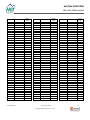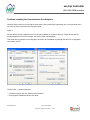
1
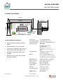
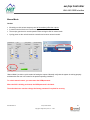
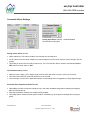
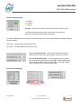
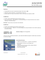
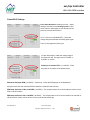
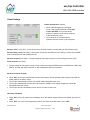
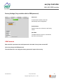
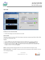
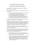
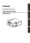
evc/epc Controller With SAE J1939 Interface evc/epc Electronic Valve Controller User Manual High Country Tek, Inc. reserves the right to improve this product at any time and without notice. This manual may contain mistakes and printing errors. The content is regularly checked and updated. Please check our website or contact our customer support for latest version. HCT accepts NO liability for technical mistakes or printing errors or their consequence. 023-00354-Rev1.6 evc/epc User Manual Copyright © High Country Tek, Inc. – 2013 1 evc/epc Controller With SAE J1939 Interface Contents Welcome ................................................................................................................................................................. 3 Warranty Information .............................................................................................................................................. 3 Product Application Guidelines ............................................................................................................................... 4 Controller Specification ........................................................................................................................................... 5 Controller Mounting Information ............................................................................................................................. 5 Electrical Diagram ................................................................................................................................................... 6 LED Diagnostic Codes ( common to both modules ) .............................................................................................. 8 Module Status LED ......................................................................................................................................... 8 Communication Status LED ............................................................................................................................ 8 Using the evc/epc with your PC .............................................................................................................................. 9 evc/epc GUI Overview .......................................................................................................................................... 11 File ................................................................................................................................................................ 11 Default Settings ............................................................................................................................................. 12 Environment .................................................................................................................................................. 12 Password ...................................................................................................................................................... 12 Help ............................................................................................................................................................... 13 Exit ................................................................................................................................................................ 13 Dashboard, Status and Graphing Windows ................................................................................................. 13 Data Logging ......................................................................................................................................................... 14 Dashboard............................................................................................................................................................. 16 Output A or B Coil Settings ................................................................................................................................... 17 Manual Mode ........................................................................................................................................................ 20 Command & Error Settings ................................................................................................................................... 21 Pulse/AIN 2 Settings ............................................................................................................................................. 24 Global Settings ...................................................................................................................................................... 25 Factory Settings (Only available with the OEM password) ................................................................................... 26 SAE J1939 ............................................................................................................................................................ 27 Operational Modes ................................................................................................................................................ 28 Single Coil Valve or Pump Control ............................................................................................................... 28 Dual Coil Valve or Pump Control .................................................................................................................. 29 Anti-Stall or Horsepower Management With Fixed Command ..................................................................... 32 Anti-Stall or Horsepower Management With Variable Command ................................................................ 34 Dual Output With Over Speed Protection ..................................................................................................... 35 Constant Flow Mode ..................................................................................................................................... 36 Closed Loop Speed Control .......................................................................................................................... 37 SAE J1939 CAN Bus ............................................................................................................................................ 39 Command Message Format ......................................................................................................................... 39 Status Message Format ................................................................................................................................ 40 Analog Values Message ............................................................................................................................... 41 Parameter Values ......................................................................................................................................... 41 Problems installing the Communication Port Adapters ........................................................................................ 43 023-00354-Rev1.6 evc/epc User Manual Copyright © High Country Tek, Inc. – 2013 2 evc/epc Controller With SAE J1939 Interface Welcome Welcome to the High Country Tek Inc. HCT is North America’s foremost independent designer and producer of modular, ruggedized digital and analog electronic controllers for the fluid power industry. From our factory in California, we build, test and produce ‘specialty’ controllers for specific functions and user programmable ‘DVC family’ to enable large area networked system solutions. The modules are used in mobile, industrial and marine applications. They are also applied successfully in other industry segments. HCT’s every module is encapsulated in solid flame resistant material for maximum durability, electrical integrity and complete environmental security. HCT is a market leader in many application arenas, including hydraulic generator, e-Fan and hydraulic fan system controls. These controllers realize significant fuel, emission and operational savings. HCT’s market neutrality offers integration with any hydraulic OEM valves, pumps, sub-systems or systems. For more information, please visit us at: www.hctcontrols.com. Cautions Changing setup values or operating modes while the machine is running may cause unintended machine movement. It may lead to possible injury or death. Any moving parts should be disabled prior to changing setup values or operating modes. In any case, exercise caution and work should be completed only by qualified personnel. Warranty Information High Country Tek guarantees this product to be free of defects in materials and workmanship for one year from the date shipped from the factory. Within this time frame, High Country Tek will provide evaluation of warranted items free of charge. Warranty repair or replacement will be at the factory’s discretion. Please have the units full Model / Part Number and Serial Number available when contacting the factory. Do not return products to the factory without a RMA (Return Material Authorization) number. 023-00354-Rev1.6 evc/epc User Manual Copyright © High Country Tek, Inc. – 2013 3 evc/epc Controller With SAE J1939 Interface Product Application Guidelines ALWAYS do the following FULLY read this manual and product data sheets BEFORE starting. Isolate the controller from all other equipment BEFORE any form of welding. Isolate the controller from ANY form of battery charging or battery boosting. Be aware of the electrical & mechanical connections, and the expected reactions of the equipment. Operate the controller within the temperature range. Use the correct tools (i.e. P.C., software) etc. Separate High Voltage AC cables from Low Voltage DC signal and supply cables. Make sure power supply is CORRECT, ELECTRICALLY CLEAN, STABLE and rated for the full load. Make sure the controller voltage & current are compatible with the equipment! All unused wires / terminals should be terminated safely. Ensure ALL connectors have no unintended SHORT or OPEN circuits. Ensure ALL connectors are wired correctly, secure, locked in place and fully connected. Disconnect or connect wires to or from the controller only when the power supply is disconnected. Use adequate screening in areas of intense Radio Frequency fields. Ensure ALL work areas are clear of personnel before operating the controller. Follow and abide by local and country health & safety standards! Software Safety Use the correct GUI and hardware combination. Cycle the power to ensure changes are accepted by the controller. When the GUI is first connected to a powered controller, a ‘Handshake’ takes place to confirm the internal software (BIOS) is compatible with the GUI. This allows the PC and the module to communicate. If an error is detected, the GUI will indicate “OFF LINE” and NOT allow communications. 023-00354-Rev1.6 evc/epc User Manual Copyright © High Country Tek, Inc. – 2013 4 evc/epc Controller With SAE J1939 Interface Controller Specification 125mm 58mm 114mm 48.5mm 7 8 9 10 11 12 6 5 4 3 2 1 CL 2x Ø5 Housing Type HCT encapsulated block Controller Mounting Information Power Supply Voltage 9 to 32VDC (Absolute maximum) Current Consumption Valve current + 50mA Quiescent (Max) Command Inputs SAE J1939 Mount controller in an easily accessible location. Mount controller to a flat, cool surface. If mounting to a hydraulic product, allow at least a 2mm air gap underneath the unit. Use BOTH mounting holes with correct hardware. 2x switched inputs (ON/Off) 2x analog inputs: One with (0-5V, 0-10V, 4-20mA) One with (0-5V, 0-10V, Pulse or Freq. - 3 to 30KHz) Input Impedance Voltage & Freq. inputs = 100k 4-20mA input = 100 Outputs DO NOT mount controller with connector facing UP if possible. 2x 3A proportional PWM (Sourcing) (Short circuit protection and open circuit alert) 1x 5VDC ±10% (Regulated voltage @ 250mA) PWM Dither Freq. Software adjustable - 33 to 500Hz Module Connector DTF15-12PB, 12-way Male Communication Mini-B USB standard Housing Material Black, Polycarbonate Encapsulation Flameproof epoxy resin Mounting 2x No.8 (5mm) screws Temperature Range -40 to +85ºC (Operational) -60 to +90ºC (Storage) NEMA/IP Rating 023-00354-Rev1.6 evc/epc User Manual Copyright © High Country Tek, Inc. – 2013 NEMA 6P/IP67 5 evc/epc Controller With SAE J1939 Interface Electrical Diagram +V Power Input 9 - 32VDC FUSE PWR 1 Enable 8 ENABLE I/P: +V = Enabled Manual Coil Select: +V = Coil B Coil Select 9 Supply Voltage +5VDC @ 250mA Ref. Out 2 4-20mA mA I/P 0-5VDC 0-10VDC VDC I/P VDC I/P AN I/P #1 3 0-5VDC Supply Voltage Signal GND 6 Electronic Valve Controller 0-5VDC 0-10VDC +5VDC @ 250mA 0-5VDC 0-10VDC VDC I/P evc VDC I/P AN or Pulse I/P #2 7 0-5VDC Supply Voltage Supply Voltage CAN_H 4 SAE J1939 I/O CAN_L 5 Coil A 10 Coil B 11 3A Proportional PWM (Sourcing) 3A Proportional PWM (Sourcing) PWR GND 12 0V start point for all heavy current return lines Mini USB Port 023-00354-Rev1.6 evc/epc User Manual Copyright © High Country Tek, Inc. – 2013 6 evc/epc Controller With SAE J1939 Interface PINOUT evc/epc controller has a 12-Pin Deutsch connector and a mini-USB port for communication. 023-00354-Rev1.6 evc/epc User Manual Copyright © High Country Tek, Inc. – 2013 7 evc/epc Controller With SAE J1939 Interface LED Diagnostic Codes ( common to both modules ) Module Status LED GREEN steady ------------------------------------------- Normal operation RED 1 pulse ---------------------------------------------- Output A short detected RED 2 pulses --------------------------------------------- Output B short detected GREEN 1 pulse ------------------------------------------ Output A open detected GREEN 2 pulses ----------------------------------------- Output B open detected RED 3 pulses --------------------------------------------- Input error detected, reference voltage error GREEN 3 pulses ----------------------------------------- Power supply error GREEN 4 pulses ----------------------------------------- Reverse retry fail error RED 4 pulses --------------------------------------------- Pot not centered at reset error ORANGE 1 pulse ---------------------------------------- State error Communication Status LED GREEN steady ------------------------------------------- Normal operation GREEN with ORANGE pulses ----------------------- Serial port (GUI) traffic ORANGE/ RED pulsing -------------------------------- Receiving SAE J1939 traffic RED 1 pulse ---------------------------------------------- SAE J1939 set point message timeout RED 2 pulses --------------------------------------------- SAE J1939 engine rpm message timeout RED 3 pulses --------------------------------------------- Pot not centered at reset error ORANGE 1 pulse ---------------------------------------- State error 023-00354-Rev1.6 evc/epc User Manual Copyright © High Country Tek, Inc. – 2013 8 evc/epc Controller With SAE J1939 Interface Using the evc/epc with your PC Install the Graphical User Interface (GUI) on a host PC. Use the default file locations for easy future update. The user has the option to choose file location. Don’t run the GUI from a network as it needs access to certain files only in the Windows directories. System Requirements Windows XP, Vista or Windows7, 100MB or greater free disk space. Insert the CD and follow the instructions. This will install the evc/epc GUI, manual and help files. Install the Com Port driver. Locate the installation file by the following route: Start HCT Products Digital Controllers evc/epc USB Serial Driver, CDMxxxxx_setup.exe To insure a complete install, run the CDMxxxxx twice. To launch evc Graphic User Interface, click Start HCT Products Digital Controllers evc/epc. Choose “evc Closed Loop” for closed loop applications, choose “evc v1.20” for open loop applications. 023-00354-Rev1.6 evc/epc User Manual Copyright © High Country Tek, Inc. – 2013 9 evc/epc Controller With SAE J1939 Interface The evc/epc can be powered by a +5V USB to allow configuration without connecting to a 12/24VDC system. A message “Supply Voltage is Low” appears on the screen. The user may communicate, change, and save settings to the unit without driving the coil(s). At start up the GUI searches the PC communication ports for the evc/epc controller. The MAC ID determines the module’s Command and Status PGN addresses on the SAE J1939 bus. The user may command multiple evc/epc modules on a single SAE J1939 bus. Please see SAE J1939 section. The default MAC ID is 1. “Find Module” or enter the “Mac ID” will locate the controller. It will restart the operation with the controller’s information and “Mac ID”. 023-00354-Rev1.6 evc/epc User Manual Copyright © High Country Tek, Inc. – 2013 10 evc/epc Controller With SAE J1939 Interface evc/epc GUI Overview File All changes made through the GUI are temporary until saved permanently. Permanently save settings to unit: Save the settings to the unit’s EEPROM (permanent memory). Permanently save settings to unit & file (.dat): Permanently save the settings to the unit’s EEPROM and to a data file that may be uploaded into any evc/epc controllers later. Settings will be lost if not permanently saved before power cycle. To reset the unit with a power cycle, you must remove both the USB cable and DC power from the unit. Restore unit to last permanent settings saved: Reload settings stored in the EEPROM. This will undo all changes made since the last Permanent Save. Restore unit settings from data file (.dat): Load the data file from the PC to the evc/epc. Restore unit from v1.03 data file: Load the previous version data file from the PC to the evc/epc. 023-00354-Rev1.6 evc/epc User Manual Copyright © High Country Tek, Inc. – 2013 11 evc/epc Controller With SAE J1939 Interface Default Settings There are four default modes of operation. Other modes of operations can be created using data files. 1. 2. 3. 4. HP Limiting or Anti-Stall with Fixed Command HP Limiting or Anti-Stall with Variable Command Single Coil Pump or Valve Control Dual Coil Pump or Valve Control Environment The Environment Menu selects the terminology for various markets. In the Automotive Environment, load control is called “Anti-Stall” and in the Agriculture environment the same function is called “HP Limiting”. Password “Enter Password” unlocks certain features of the GUI. Please contact your point of sales to obtain a password if required. Passwords are ‘cAsE SeNsitivE’. 023-00354-Rev1.6 evc/epc User Manual Copyright © High Country Tek, Inc. – 2013 12 evc/epc Controller With SAE J1939 Interface Help Reconnect with controller: The GUI will reset communication with the module, and re-read and update all variables. Print Settings to text: Will print all settings to your PC default printer, or print to a text file, tab delimited. The text file may be viewed with Notepad, Word, or Excel. About Controller: Will display information about the evc/epc, the GUI revision, serial number, contact information etc. Manual: Will open the folder in C:\\HCT products/Digital Controllers, or browse to other locations. Exit Exits the evc/epc GUI and frees up the com port and memory used by the application. You can exit the GUI with or without saving the changes. Dashboard, Status and Graphing Windows They give real time overview of the controller health, operation of the system and condition of inputs, outputs and any alarms. 023-00354-Rev1.6 evc/epc User Manual Copyright © High Country Tek, Inc. – 2013 13 evc/epc Controller With SAE J1939 Interface Each graph tracks two variables that are individually scaled. Select the variable from the Pull Down Menus. “Y” axis is automatically scaled to the respective minimum and maximum values. To customize the scaling, simply select a value on the graph and enter the desired value. Data Logging “Log Data” and save it in “.xls” format. The data file size is only limited by the PC hard-drive capacity. Each log begins with a list of unit settings and followed by real time operational information. The sample rate depends on the workload of the PC and the evc/epc at recording. A timestamp scales the logs appropriately. Subsequent logs may be stored in a new file or appended to the original log file by selecting the original file. The log file may not have all of the Excel formatting. Excel may declare an unknown file format. If it does, select ‘Open’ and the information will display normally. 023-00354-Rev1.6 evc/epc User Manual Copyright © High Country Tek, Inc. – 2013 14 evc/epc Controller With SAE J1939 Interface Example data files are saved to your PC during the installation. When loading factory default data files, select “Environment”, then select the desired default file. Default Data files will overwrite any settings in the unit. Adjust the Coil Settings first, then other settings as needed. In Agriculture or Automotive you will have Four files: 1. HP Limiting with Variable Command /Anti-stall with Variable Command. Monitors RPM, the command input, and adjusts the output accordingly. 2. HP Limiting with fixed command/Anti-stall with fixed command. Monitors RPM and adjusts the output accordingly. 3. Single Coil Pump Control / Valve Control Controls the single-coil pump/valve in open loop mode. 4. Dual Coil Pump Control / Valve Control Controls the dual-coil pump(s)/valve(s) in open loop mode. 023-00354-Rev1.6 evc/epc User Manual Copyright © High Country Tek, Inc. – 2013 15 evc/epc Controller With SAE J1939 Interface Dashboard PWM% A/B – displays the PWM duty cycle output for coil A and B. The PWM% B will be “Grayed Out” when Coil B is disabled. % Demand A/B – displays the percent of demand for the output with respect to the Maximum and Minimum Current settings. The % Demand B will be “Grayed Out” when Coil B is disabled. Coil Current A/B – displays the output current. The Coil B Current will be “Grayed Out” when Coil B is disabled. Enabled/Disabled – displays the current state of the enable input. Command Volts/mAmps – Displays the voltage or current at the Command input. Reference Volts – Displays the voltage at the User Reference output. Supply Volts – Displays the voltage at the main Power Supply Input. Average Coil Current – Applies averaging function to the displayed coil current. It does not affect coil current. 023-00354-Rev1.6 evc/epc User Manual Copyright © High Country Tek, Inc. – 2013 16 evc/epc Controller With SAE J1939 Interface Output A or B Coil Settings Select Coil B Active for a Dual Coil Valve Control. Enter minimum, maximum current and dither frequency according to the valve specification. Enter UP or DOWN ramp times. “Change Settings” to apply the changes to the unit’s temporary memory. Once the system is running, fine tune these settings. Always Active (ON) – Output A is always active and cannot be set “OFF”. Coil B – active (ON/OFF) – Enables/Disables Output B. Current feedback (ON/OFF) When Current Feedback is “ON”, coil current output is monitored and adjusted proportionally to the demand within the coil max and min settings. Current Feedback compensates for supply voltage and coil temperature changes. When disabled, the output’s waveform is adjusted proportionally to the demand between 0% and 100% PWM Duty Cycle. Inverted (ON/OFF) When Inverted is “ON”, the output is inversely proportional to the input. This is used with normally closed valves. When Inverted is “OFF”, the output is proportional to the input. 023-00354-Rev1.6 evc/epc User Manual Copyright © High Country Tek, Inc. – 2013 17 evc/epc Controller With SAE J1939 Interface Coil A/B Min Current (0 to 2.5Amps) Determines the min current or duty cycle. Fine tune this value to balance machine safety and valve responsiveness. Typical values for this can be found in the manufacturer’s information. Coil A/B Max Current (0 to 3Amps) When Current Feedback is “ON”, it determines the max output current. Typical values can be found in the valve manufacturer’s information. When Current Feedback is “OFF”, the Coil A/B Min Current setting does not apply and is grayed out. The Max Current is used as an internal reference to declare a coil short condition when the output current is 0.5A higher than the max current setting. When Current Feedback is “OFF”, the output PWM duty cycle (0-100%) matches the percent of demand. The current will change when supply voltage and/or coil temperature changes. In this example, the output PWM duty cycle (0-100%) matches the percent of demand. The output current will change when supply voltage and/or coil temperature changes. The evc/epc does not declare an error because the output current 1.16A is not 0.5A higher than the max setting 0.7A. In this example, the evc/epc declared an error because the output current 1.16A is 0.5A higher than the max setting 0.63A. 023-00354-Rev1.6 evc/epc User Manual Copyright © High Country Tek, Inc. – 2013 18 evc/epc Controller With SAE J1939 Interface Ramp Up (1 to 65,000 Mini Seconds) – Determines the time for Output A or B to ramp UP from minimum to maximum current. Ramp Down (1 to 65,000 Mini Seconds) – Determines the time for Output A or B to ramp Down from maximum to minimum current. Coil A&B PWM Hz (33 to 500Hz) – This is the PWM or Dither frequency according to the valve spec. (Sun cartridges are 140Hz). Ignore Open (ON/OFF) When Ignore Open is “ON” and Current Feedback is “ON”, the evc/epc will not declare an error when the output duty cycle reaches 100%. When Ignore Open is “OFF” and Current Feedback is “ON”, the evc/epc will declare an error when the output duty cycle reaches 100%. When Current Feedback is “OFF”, Ignore Open does not have any effect. 023-00354-Rev1.6 evc/epc User Manual Copyright © High Country Tek, Inc. – 2013 19 evc/epc Controller With SAE J1939 Interface Manual Mode Caution All settings on this tab are temporary and will immediately affect the outputs. In manual mode all limits and controls are bypassed. The evc/epc goes back to normal operation when exiting the GUI in manual mode. Cycling power on the unit will reset the controller and remove manual override. “Manual Mode” provides a quick method of testing the outputs. Manually verify that the system is working properly and determine the max coil current for the present operating conditions. To unlock manual control, you must enter the OEM password. When the GUI is initially purchased, the OEM password is included. The authorized user can then change the factory password if required for security. 023-00354-Rev1.6 evc/epc User Manual Copyright © High Country Tek, Inc. – 2013 20 evc/epc Controller With SAE J1939 Interface Command & Error Settings Analog Input Active (On/Off) – Enables/Disables the command analog input. Analog Center Active (On/Off) When enabled, the “Pot Center Voltage” becomes the zero demand point. Coil A is driven from the center voltage to the max voltage and coil B is driven from the center voltage to the min voltage This setting is used in Dual Coil Valve Control only. The “Coil Selection Active” switch is automatically turned OFF when the Center Active is “ON”. Coil Selection Active (On/Off) When the input is High, (+5V to Supply Volts) coil B is active and when Low (0V to 2.5V) coil A is active. This feature allows the full command resolution on coil A and B. As an example, it is used in the applications where a reciprocating action is triggered by a single high-low input. Pot Center Error Detection at Initial Turn On When ON, the module verifies the analog input is in the center deadband range before enabling the output(s) after the initial power up. Once the command is centered, the outputs will be enabled. This safety feature ensures that the system will NOT immediately go to the previous settings after cycling the power. 023-00354-Rev1.6 evc/epc User Manual Copyright © High Country Tek, Inc. – 2013 21 evc/epc Controller With SAE J1939 Interface Command Input Selection 0-5VDC 0-10VDC 4-20mA Inverted – reverses the response of the command input to output current. i.e., Minimum command input will give 100% output current and the Maximum command input gives 0% output current. For industrial applications that use ±5VDC or ±10VDC, please use a HCT Command Signal Conditioner with the evc/epc controller. CSC-0505 – accepts ±5VDC and converts to 0-5V. CSC-1005 – accepts ±10VDC and converts to 0-5V. Loss of Pulse Signal Time – (1mS to 65Sec) Sets the time delay before an error of loss of any “Pulse signal” causes to be declared. Coil A or B default set-point – (0-100%) Output A or B will ramp to this value when the input limits are exceeded or J1939 message times out, or reference voltage drops to below 4VDC, or the supply voltage drops to below 9VDC, or the pulse signal is lost. Command Limit Settings 023-00354-Rev1.6 evc/epc User Manual Copyright © High Country Tek, Inc. – 2013 22 evc/epc Controller With SAE J1939 Interface Dead band The Dead band can only be used when the Analog Center Active is “ON”. Dead band is split one half above, one half below the center point. 0.2VDC means coil A output current starts at 2.6VDC, coil B output current starts at 2.4VDC. Pot Maximum It sets the max command input to have the maximum current. If the command input is > POT Maximum + the Command Margin, the evc/epc will declare an error and the outputs go to the default settings. Pot Center – Sets the value of the center of the dead band. Pot Minimum It sets the min command input to have the minimum current. If the command input is < Minimum - the Command Margin, the evc/epc will declare an error and the outputs go to the default settings. Reference voltage is 5V ±10% @ 250mA. HCT has a manual command potentiometer – part number 999-10205 that outputs 0.5-4.5VDC when connected to a +5VDC user voltage. Auto Calibrate Pot Input Calibrate the command limits – i.e. joystick or foot pedal etc. When the button is clicked, a box will appear with instructions. Adjust the input from full High to full Low, and then adjust to the neutral or crossover point. “OK” to save the values. 023-00354-Rev1.6 evc/epc User Manual Copyright © High Country Tek, Inc. – 2013 23 evc/epc Controller With SAE J1939 Interface Pulse/AIN 2 Settings Pulse Input Selections (Analog or Pulse) – Select analog to use this input as analog input 2 for dual valve control or select pulse to use this input as the pulse input for anti-stall function. 0-5V, 0-10V & ±1V (Enabled/OFF) – Select the voltage range that matches the analog input signal. The ±1V only applied to Pulse input. For anti-stall function, match the voltage range to the Pulse Pick UP. The signal can be 0-5VDC, or 0-10VDC, or ±1VDC. Pulses per revolution PPR - (1 to 65535) – Enter the pulse per revolution of the speed sensor. Maximum displayed RPM (1 to 65535) – Visual only - scales the RPM gauge on the Dashboard. Keep this value near the maximum RPM to assure the resolution and accuracy. RPM slow Set-Point or Max Load RPM (1 to 65535) – The set-point where coil A current starts to reduce in AntiStall or HP limit modes. RPM stop Set-Point or No Load RPM (1 to 65535) – The set-point where coil A current reaches 0 in Anti-Stall or HP limit modes. If auto-reverse is ON, reverse cycle will start at this rpm. 023-00354-Rev1.6 evc/epc User Manual Copyright © High Country Tek, Inc. – 2013 24 evc/epc Controller With SAE J1939 Interface Global Settings Enable Auto-Reverse (On/Off) When in HP Management or Anti-Stall mode, if the measured RPM is ≤ RPM Stop or No Load RPM, coil A current ramps down to 0, and then coil B current ramps up to the Reverse Set- point. The module will try to restart normal operation after the reverse cycle completes. Reverse Time (0 to 65 Sec) – It sets the time that coil B will remain in reverse during an Auto-Reverse cycle. Reverse Retry Count (0 to 65535) –The number of times the Auto-Reverse cycle will try to restore normal RPM before declaring a fault and disabling the unit. Reverse set-point (0 to 100%) – The percentage of Imax output current for coil B during the reverse cycle. Fixed set-point (0 to 100%) The percentage of Imax output current for coil A when the measured RPM is above the RPM slow or Max Load RPM in “anti-stall with fixed command” or “HP management with fixed command”. Recover from loss of signal When “ON”, the evc/epc automatically recovers and returns to normal operation after the pulse input and the analog input(s) are back in range. The evc/epc automatically recovers from a SAE J1939 message timeout error. The evc/epc automatically recovers when the reference voltages or the supply voltages are outside the acceptable limits and recover. The evc/epc will not automatically recover from a coil open or short error. Hard stop if disabled When “ON”, coil A or B outputs are immediately set to zero without ramps whenever the enable input is set to “OFF”. When “OFF”, the coil A or B outputs ramp down to zero when the enable input is set to “OFF”. 023-00354-Rev1.6 evc/epc User Manual Copyright © High Country Tek, Inc. – 2013 25 evc/epc Controller With SAE J1939 Interface Factory Settings (Only available with the OEM password) Reset Unit It restores the controller to the last permanently saved configuration. Serial Number Specific for this unit, reference to the factory record. Start Date The date when the evc/epc is connected to the GUI for the first time. OEM Password When the GUI is purchased, the initial password is included. If lost, please contact HCT. Users may change the OEM password. The authorized user can change the factory password if required for security 023-00354-Rev1.6 evc/epc User Manual Copyright © High Country Tek, Inc. – 2013 26 evc/epc Controller With SAE J1939 Interface SAE J1939 Set Point A or B % and Set Point RPM A SAE J1939 message can set the demand for coil A and B. Measured RPM The evc/epc controller can accept an SAE J1939 message containing the measured engine RPM on PGN: 0xF004 (61444) Source Address (SA): 0x00. Timeout The box is red when the SAE J1939 message has timed out indicating a bus, connection or data error. Outputs for coil A and B will ramp to the default settings according to the “Command & Error” page. If “Recover from loss of signal" is “ON”, the outputs will resume normal operation when a valid SAE J1939 message is received. The box becomes green. MAC ID – Displays and allows changing the MAC ID. It is the network address for this specific evc/epc. Report Analog Values – When “ON”, it will transmit the values of the analog inputs on SAE J1939 Bus. It does not force to change the settings. 023-00354-Rev1.6 evc/epc User Manual Copyright © High Country Tek, Inc. – 2013 27 evc/epc Controller With SAE J1939 Interface Operational Modes Single Coil Valve or Pump Control Only Coil A is used in this function. 0-5VDC gives coil A 0-100% current output. Coil A Current max min 0 min max Command Voltage 023-00354-Rev1.6 evc/epc User Manual Copyright © High Country Tek, Inc. – 2013 28 evc/epc Controller With SAE J1939 Interface Dual Coil Valve or Pump Control One Valve with coil A and B when Center Active is ON Coil B Current Center (2.5/5V) Coil B max Coil A Current Coil A max Coil B min Coil A min Analog Center Active (Enabled/OFF) – when enabled, 0-2.5VDC drives coil B, 2.5-5VDC drives coil A. POT Center Error Detection at Initial Turn On (Enabled/OFF) – when enabled, we have a neutral start position for machine safety. 5/10V 0 Min 023-00354-Rev1.6 Max Min Max Command Input evc/epc User Manual Copyright © High Country Tek, Inc. – 2013 29 evc/epc Controller With SAE J1939 Interface One Valve with coil A and B when Coil Selection is ON Coil A Current Coil B Current max max min min 0 min max Command Voltage 0 min max Command Voltage Coil Selection Active (Enabled/OFF) – when enabled, Analog Center Active is automatically turned OFF. 0-5V gives both coils 0-100% PWM current output. But there is only one output at one time. When the digital input 2 is OFF, coil A is working. When the digital input 2 is ON, coil B is working. 023-00354-Rev1.6 evc/epc User Manual Copyright © High Country Tek, Inc. – 2013 30 evc/epc Controller With SAE J1939 Interface Two Valves, Coil A for Valve 1, Coil B for Valve 2 Coil A Current Coil B Current max max min min 0 min max Command Voltage 0 min max Analog Input 2 Voltage Coil A and B are independently controlled by 2 Potentiometers or Joysticks. Coil A follows the Command Volts. Coil B follows the Pulse Volts because the pulse input Pin is used as the Analog input 2. 0-5V gives both coils 0-100% PWM current output. But there are two outputs at the same time. 023-00354-Rev1.6 evc/epc User Manual Copyright © High Country Tek, Inc. – 2013 31 evc/epc Controller With SAE J1939 Interface Anti-Stall or Horsepower Management With Fixed Command The Anti-Stall function reduces the current to prevent the engine from stalling during a sudden external load increase. The fixed set-point determines the max forward speed of the work function. The reverse set-point determines the max reverse speed of the work function. At start-up the measured RPM must initially reach the “RPM Slow” set-point to allow the evc/epc to ramp up Coil A. This ensures that the prime mover has started and is at a stable speed. 023-00354-Rev1.6 evc/epc User Manual Copyright © High Country Tek, Inc. – 2013 32 evc/epc Controller With SAE J1939 Interface When the measured RPM is above the “RPM Slow” (1900RPM), Coil A current is determined by the Fixed Setpoint. When the measured RPM starts to drop below the “RPM Slow”, Coil A current is reduced proportionally to the measured RPM. Coil A current becomes zero when the measured RPM reaches “RPM Stop” (1800RPM) or below. When “Auto-Reverse” is “OFF”, Coil A current stays at 0 until the RPM increases to above “RPM Stop”, it will increase proportionally to the measured RPM. Coil Current Coil A Current @ fixed Set-point Anti-stall full effect Anti-stall starts 0 RPM Stop RPM Slow Engine rpm When “Auto-Reverse” is “ON”, Coil A current stays at 0 and Coil B current will ramp up to the Reverse Setpoint. After the reverse cycle is over, if the measured RPM increases to above RPM Stop, Coil A current increases proportionally until reaching the fixed set-point. If not, the evc/epc will re-enter reverse for “Reverse Retry Count” times, each time remaining in reverse for “Reverse Time” duration. If the Reverse Retry Count is depleted and the measured RPM remains below RPM Stop, the evc/epc will declare an error and output the default settings to coil A. Coil Current Coil A Current @ fixed Set-point Coil B Current @ reverse Set-point Anti-stall starts Anti-stall full effect 0 RPM Stop 023-00354-Rev1.6 RPM Slow Engine rpm evc/epc User Manual Copyright © High Country Tek, Inc. – 2013 33 evc/epc Controller With SAE J1939 Interface Anti-Stall or Horsepower Management With Variable Command This mode is similar to the “Anti-stall with Fixed Command” or “Horsepower Management with Fixed Command”. The only difference is that this function allows a variable command input to control the forward speed of the work function. The max reverse speed of the work function is set by the GUI. The input can be from an external POT, a joystick or a SAE J1939 message. At any given forward speed of the work function, the Anti-Stall function reduces the current to prevent the engine from stalling during a sudden external load increase. 023-00354-Rev1.6 evc/epc User Manual Copyright © High Country Tek, Inc. – 2013 34 evc/epc Controller With SAE J1939 Interface Dual Output With Over Speed Protection It works with dual fixed displacement pumps and switches valves ON or OFF according to the measured RPM. The measured engine RPM can be from the alternator ‘R’ terminal, PPU, or SAE J1939. BOTH outputs are ON when below ‘A’ setting. When the measured RPM ≥ Set-point A RPM, coil A ramps down to minimum current. When the measured RPM ≥ Set-point B RPM, coil B ramps down to minimum current NOTE: with Ramps set to minimum times, the outputs will drive ON/OFF valves 023-00354-Rev1.6 evc/epc User Manual Copyright © High Country Tek, Inc. – 2013 35 evc/epc Controller With SAE J1939 Interface Constant Flow Mode Constant Flow Mode operates with a variable displacement pump. It reduces the output of coil A to reduce the pump displacement when the engine rpm increases, maintaining constant flow output of the pump. When the measured RPM is 1500rpm, output A provides max current. When the measured RPM is 1800rpm, output A provides 0 current. 023-00354-Rev1.6 evc/epc User Manual Copyright © High Country Tek, Inc. – 2013 36 evc/epc Controller With SAE J1939 Interface Closed Loop Speed Control The “evc Closed Loop” Graphical User Interface must be selected. Set the coil min, max current and the PWM frequency according to the valve specification. The reference and the feedback can be set by either of the command voltage, pulse voltage, pulse rpm, J1939, etc. In this example, the reference A is set by the command voltage. The feedback is set by the pulse rpm. The maximum displayed RPM is for the display only. In this example, the analog input demands 95% of the maximum displayed rpm which is 1900rpm. The measured rpm is 1892rpm. The evc/epc controller will increase the current to maintain 1900rpm until the current reaches the max setting. 023-00354-Rev1.6 evc/epc User Manual Copyright © High Country Tek, Inc. – 2013 37 evc/epc Controller With SAE J1939 Interface When the measured rpm increases to above 1900rpm, the evc/epc will reduce the current to maintain 1900rpm until it reaches 0. The closed loop control is a dynamic process. The evc/epc constantly changes the current to maintain the reference rpm. If the overshoot of the speed is big, the changing rate of the current is fast. If the overshoot of the speed is small, the changing rate of the current is slow. The same working principle applies when different signals are used as the reference and the feedback. 023-00354-Rev1.6 evc/epc User Manual Copyright © High Country Tek, Inc. – 2013 38 evc/epc Controller With SAE J1939 Interface SAE J1939 CAN Bus The evc/epc can be controlled by messages received over the SAE J1939 Bus. The EEC1 (PGN: 61444 SA: 0) engine RPM (SPN: 190) can be monitored for use in anti-stall and closed loop operations. The proprietary SAE J1939 Command Message (PGN: 65281 through 65407 SA: 34) can be monitored for Coil A, Coil B and RPM Set points for various operation modes. This address is adjusted based on the Module ID. The relationship of the Module ID and the Command Message address is defined in a chart at the end of this section. The evc/epc can transmit its status over the SAE J1939 Bus. The proprietary SAE J1939 Status Message (PGN: 65409 through 65535 SA: 34) is a multiplexed message with the first data byte indicating message 1 Status or message 2 Analog Values. This address is adjusted based on the Module ID. The relationship of the Module ID and the Status Message address is defined in a chart at the end of this section. When the SAE J1939 Command Message is enabled, the Status Message will be transmitted. If Report Analog Values is enabled on the SAE J1939 tab, the Analog Values will be transmitted. The content of the Status and Analog Values messages are detailed below. Command Message Format Transmission Repetition 40mS Data Length 8 Data Page 0 PDU Format 255 PDU Specific Module ID # Priority N/A Parameter Group Number 65281 Through 65407 Start Position Length Parameter Name 1 1 Byte Always = 1 2-3 2 Bytes Coil A Set point 4-5 2 Bytes Coil B Set point 6-7 2 Bytes RPM Set point 023-00354-Rev1.6 evc/epc User Manual Copyright © High Country Tek, Inc. – 2013 (FF01 Through FF7F) 39 evc/epc Controller With SAE J1939 Interface Status Message Format Transmission Cycle Time Data Length Data Page PDU Format PDU Specific Priority Parameter Group Number 100mS 8 0 255 Module ID + 128 3 65409 Through 65535 (FF81 Through FFFF) Status Message Start Position 1 2.1 2.2 2.3 2.4 2.5 2.6 2.7 2.8 3.1 3.2 3.3 3.4 3.5 3.6 3.7 3.8 4.1 4.2 4.3 4.4 4.5 4.6 4.7 4.8 5-6 7-8 023-00354-Rev1.6 Length 1 Byte 1 bit 1 bit 1 bit 1 bit 1 bit 1 bit 1 bit 1 bit 1 bit 1 bit 1 bit 1 bit 1 bit 1 bit 1 bit 1 bit 1 bit 1 bit 1 bit 1 bit 1 bit 1 bit 1 bit 1 bit 2 Bytes 2 Bytes Parameter Name Always = 1 (Status) Command Input Error Reference Voltage Error Pulse Input LOS Power Supply High Power Supply Low Coil A Msg Timeout Coil B Msg Timeout RPM Msg Timeout not used Reverse Cycle Active Digital Input 1 State Digital Input 2 State Coil A Short Coil A Open Coil B Short Coil B Open Process A Ramping Process B Ramping Command Input Not Centered Reverse Cycle Retry Timeout System in Startup Mode System in Shutdown Mode not used not used Coil A Current (mA) Coil B Current (mA) evc/epc User Manual Copyright © High Country Tek, Inc. – 2013 40 evc/epc Controller With SAE J1939 Interface Analog Values Message Start Position 1 2-3 4 5-6 7 8 Length 1 Byte 2 Bytes 1 Byte 2 Bytes 1 Byte 1 Byte Parameter Name Always = 2 (Analog Value) Command Input Value (volts x100 or mA x100) 0 = Command Volts, 1 = Command mA Pulse Input volts x100 Always = 0 Always = 0 Parameter Values Coil n Set point Data Length Resolution Data Range Operational Range 2 Bytes 0.00152903 %/bit, 0 offset 0% to 100% 0 to 100% Coil n Current Data Length Resolution Data Range Operational Range 2 Bytes 1mA/bit, 0 offset 0 to 65535mA 0 to 3000mA RPM Data Length Resolution Data Range Operational Range 023-00354-Rev1.6 2 Bytes 0.125 rpm/bit, 0 offset 0 to 8,031.875 rpm 0 to 8,031.75 rpm evc/epc User Manual Copyright © High Country Tek, Inc. – 2013 41 evc/epc Controller With SAE J1939 Interface Module Id Command PGN 1 2 3 4 5 6 7 8 9 10 11 12 13 14 15 16 17 18 19 20 21 22 23 24 25 26 27 28 29 30 31 32 33 34 35 36 37 38 39 40 41 42 43 FF01 FF02 FF03 FF04 FF05 FF06 FF07 FF08 FF09 FF0A FF0B FF0C FF0D FF0E FF0F FF10 FF11 FF12 FF13 FF14 FF15 FF16 FF17 FF18 FF19 FF1A FF1B FF1C FF1D FF1E FF1F FF20 FF21 FF22 FF23 FF24 FF25 FF26 FF27 FF28 FF29 FF2A FF2B 023-00354-Rev1.6 Status PGN FF81 FF82 FF83 FF84 FF85 FF86 FF87 FF88 FF89 FF8A FF8B FF8C FF8D FF8E FF8F FF90 FF91 FF92 FF93 FF94 FF95 FF96 FF97 FF98 FF99 FF9A FF9B FF9C FF9D FF9E FF9F FFA0 FFA1 FFA2 FFA3 FFA4 FFA5 FFA6 FFA7 FFA8 FFA9 FFAA FFAB Module Id Command PGN 44 45 46 47 48 49 50 51 52 53 54 55 56 57 58 59 60 61 62 63 64 65 66 67 68 69 70 71 72 73 74 75 76 77 78 79 80 81 82 83 84 85 86 FF2C FF2D FF2E FF2F FF30 FF31 FF32 FF33 FF34 FF35 FF36 FF37 FF38 FF39 FF3A FF3B FF3C FF3D FF3E FF3F FF40 FF41 FF42 FF43 FF44 FF45 FF46 FF47 FF48 FF49 FF4A FF4B FF4C FF4D FF4E FF4F FF50 FF51 FF52 FF53 FF54 FF55 FF56 Status PGN FFAC FFAD FFAE FFAF FFB0 FFB1 FFB2 FFB3 FFB4 FFB5 FFB6 FFB7 FFB8 FFB9 FFBA FFBB FFBC FFBD FFBE FFBF FFC0 FFC1 FFC2 FFC3 FFC4 FFC5 FFC6 FFC7 FFC8 FFC9 FFCA FFCB FFCC FFCD FFCE FFCF FFD0 FFD1 FFD2 FFD3 FFD4 FFD5 FFD6 evc/epc User Manual Copyright © High Country Tek, Inc. – 2013 Module Id Command PGN 87 88 89 90 91 92 93 94 95 96 97 98 99 100 101 102 103 104 105 106 107 108 109 110 111 112 113 114 115 116 117 118 119 120 121 122 123 124 125 126 127 FF57 FF58 FF59 FF5A FF5B FF5C FF5D FF5E FF5F FF60 FF61 FF62 FF63 FF64 FF65 FF66 FF67 FF68 FF69 FF6A FF6B FF6C FF6D FF6E FF6F FF70 FF71 FF72 FF73 FF74 FF75 FF76 FF77 FF78 FF79 FF7A FF7B FF7C FF7D FF7E FF7F Status PGN FFD7 FFD8 FFD9 FFDA FFDB FFDC FFDD FFDE FFDF FFE0 FFE1 FFE2 FFE3 FFE4 FFE5 FFE6 FFE7 FFE8 FFE9 FFEA FFEB FFEC FFED FFEE FFEF FFF0 FFF1 FFF2 FFF3 FFF4 FFF5 FFF6 FFF7 FFF8 FFF9 FFFA FFFB FFFC FFFD FFFE FFFF 42 evc/epc Controller With SAE J1939 Interface Problems installing the Communication Port Adapters Windows does not like Com ports with the same name, and some devices might hang onto a com port when not in use. Here is how to clean and remove problem ports. Option 1 Devices that have been installed but are not currently available are "phantom devices". These devices are not usually displayed in the device manager, but can be made to be displayed. This allows device properties to be changed or devices to be uninstalled even though the device is not physically connected to the PC. Control Panel System Properties "Advanced" option and click "Environment Variables" In the System Variables sections, click "New" 023-00354-Rev1.6 evc/epc User Manual Copyright © High Country Tek, Inc. – 2013 43 evc/epc Controller With SAE J1939 Interface "DevMgr_Show_NonPresent_Devices" and set the value to 1, then click OK. Close the System Properties panel. Open the Device Manager "View” Show Hidden Devices". Device Manager will show all hidden and phantom devices. Uninstall the phantom devices by right clicking on them, and 'delete'. Reboot the PC. When you connect PC to the unit, give the computer time to find and install the driver. Option 2 In control panel, “Add or Remove Programs” Remove old versions of FTDI software. Remove Windows Driver Package - FTDI CDM Driver Package. 023-00354-Rev1.6 evc/epc User Manual Copyright © High Country Tek, Inc. – 2013 44 evc/epc Controller With SAE J1939 Interface Minin icul u e lo a ion ane li eu e on e-c clin uc ion - oad e icle Fo e ood ul ecla a ion il Field al a e and De oli ion oolin aau ecial e e oe o e i In e al e en olu ion Mili a ui on ol ene a ion ion on ol For a full list of authorized distributors worldwide, please visit a ed D i e u on ol c con ol co di i uo inde For customer service, pricing, order placement and application support, contact us through E-mail at in o c con ol co c con ol co A SUN Hydraulics C ompany i oun e Inc 208 Gold Flat Court Nevada City, CA, 9 9 9 Tel (1) 30 2 323 Fax (1) 30 2 32