1
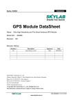
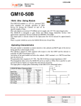
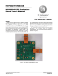
Simplify The Complexity
SkyNav EVB10
GPS Modules Eval. Board
User Manual
Skylab M&C Technology Co., Ltd
Room.801, Building.211, Terra Industrial Park,
Futian District, Shenzhen, China
Tel: (86) 755-83408280
Fax: (86) 755-83408560
Website: www.skylab.com.cn
N 22° 32' 09.70", E 114° 01' 11.71"
Copyright © Skylab 2006
SkyNav EVB10
Version History:
Title
EVB10
Subtitle
GPS Modules Eval. Board
Doc Type
User Manual
Doc Id
EVB-UM-1.0
Revision Index
Date
Initial Release
30 Jul. 06
Comments
Copyright:
Skylab M&C Technology Co., Ltd copyrights the SkyNav EVB10 user manual with all rights reserved.
No part of this document may be reproduced, modified, publicly displayed, transmitted in any form or by
any means or used for any commercial purpose, without the prior written permission of Skylab Company.
Jul.2006 EVB-UM-1.0
1
SkyNav EVB10
General Description
This document provides a description of the hardware features and usage of EVB10. It contains RF
connector applied active antenna input and RS232 serial port and USB port to connect with PC, there is a
MCU and two digital “8” LED display on board so that can work in stand-alone mode. It will allow GPS end
user to evaluate and test Skylab GPS modules for navigation and positioning performance as well as to
update the firmware of modules.
Key Features
The EVB10 Evaluation board serves as evaluation platform, design example, and programmer to update
firmware of GM10 and GB10 modules, the following summarizes the board features:
Operating voltage: DC9~15V
Selectable RS232 serial port and USB port to PC
Built in MCU for working stand alone mode
Two digital “8” LED display the working status of GB10 and GM10
Multi-LED lights indicate the status of power up and system working
Multi-Jumpers for configulating working mode
Reset button for reset the GM10 or GB10 modules
SMA RF connector
Operating temperature: -10~+70°C
Functional Description
The EVB10 can be connected with PC through RS232 serial port or USB port and linked with uNav Orion
Analyzer software through NMEA or UBP protocol, it can be used to evaluate and test Skylab’s GB10 and
GM10 products for navigation and positioning performance based on this software. About the usage and
introduction of this software, pls. refer to the user manual of uNav Orion Analyzer. About the format and
usage of NMEA and UBP protocol pls. refer to NMEA and UBP protocol user manual.
The end user can update the firmware of GB10 or GM10 with uNav Orion Analyzer so that keep the newest
version released by Skylab and perform more advanced features meet various requirements. With
regarding to how to update pls. Refer to the user manual of uNav Orion Analyzer.
Also, The EVB10 can work in stand-alone mode with MCU built in board. The MCU controller can monitor
the data of GPS modules output, analyze the NMEA or UBP protocol, and display the GB10 or GM10
working status, this will be in favor of end user to check and test the module’s “good” or “failure” quickly
before solder these modules on system board.
The EVB10 is strictly an evaluation board. It can be used for other purposes also, but it should not be
interpreted as a production worthy design. Instead, the EVB10 provides a design example, which
demonstrates typical achievable performance with the GB10 or GM10 in a variety configuration.
2
Jul.2006 EVB-UM-1.0
SkyNav EVB10
EVB10 Picture
GM10 RF Input
GB10
GM10 Module
Display
Jumper1
LED4
Jumper2
MCU
Reset Button
LED3
LED5
LED1
LED6
LED2
Jumper3
Power Switch
Power Input
RS232 Port
USB Port
Power Supply
The width input range from DC 9V to DC 15V
Power Switch
A self-locking switch. Press the button to power on the EVB10.
Reset Button
Push in briefly to restart the GM10 or GB10.
Antenna Input
The EVB10 is designed for supporting the active antenna. The gain of active antenna should be no less
than 15dB. The maximum noise figure should be no more than 2.5dB.
GM10 Socket
Place GM10 module in this socket, pls. Ensure that spring pin connect with posthole of GM10 well. And
noted the position of first pin.
Jul.2006 EVB-UM-1.0
3
SkyNav EVB10
GB10 Connector
Insert GB10 Module in this connector, pls. Noted the position of first pin of GB10
RS232 and USB Interface
Selectable interface to connect EVB10 with PC, pls. Install the USB driver before use the USB port.
Display and Indicators
The EVB10 have two digital “8” display and multi-LED lights to display the various working status of EVB10
and GB10 or GM10, the following items describer these status:
LED1 (Green): light up when power switch turn on
LED2 (Red): Flicker when MCU receive or transfer data to GPS modules
LED3 (Yellow): Flicker when GPS module don’t find the available satellites or don’t positioning
LED4 (Green): Flicker when GPS modules find the available satellites and start positioning
LED5 (Red): Flicker when update the firmware of GPS modules
LED6 (Red): Flicker when GPS modules transfer the data out
Two digital “8”: Display the numbers of available satellites
Note: The LED2~LED5 and the two digital “8”display are available in the case of MCU monitor the output
data of GPS module (JP2 MCU RXD and TXD in “connected” position), otherwise. Only the LED1 and
LED6 are available (JP2 MCU RXD and TXD in”open” position).
Jumper and Setting
The EVB10 can be configured for various purposes through jumpers; the following table identifies these
jumpers and their normal setting:
Jumper ID
JP1
JP2
JP3
4
Setting
Description
Default
Left Connected
GM10 Boot from UART
Open
Right Connected
GM10 Boot from Flash (Normal Mode)
Connected
MCU RXD
Connect MCU with Module UART
Connected
MCU TXD
Connect MCU with Module UART
Connected
RS232 TXD
Connect PC with Module UART Through RS232
Open
RS232 RXD
Connect PC with Module UART Through RS232
Open
USB TXD
Connect PC with Module UART Through USB
Open
USB RXD
Connect PC with Module UART Through USB
Open
Left Connected
GM10 Boot from UART
Open
Right Connected
GM10 Boot from Flash
Connected
Jul.2006 EVB-UM-1.0
SkyNav EVB10
EVB10 Usage
Note: The EVB10 can just evaluate and test a type GPS module at the same time, pls. Don’t fix GB10 and
GM10 on board at the same time.
Stand-alone Mode: To check and test GB10 or GM10 “good” and “failure”
Step 1: Insert the GB10 or GM10 in respective socket and connect active antenna to module’s RF input.
Step 2: Set up JP2 to connect MCU RXD and TXD with GPS module
Step 3: Press power switch
Here, The two digital “8” display will display two “--” before the GPS module transfer the data out, stay a
while, it will display “00” when GPS module start to seek and capture satellites, after several or tens
seconds depended on various start mode, it will display the numbers of available satellites, and indicate
that the GPS module has found the position of itself.
PC-based Mode: To evaluate and test GPS modules.
Step 1: Insert the GB10 or GM10 in respective socket and connect active antenna to module’s RF input.
Step 2: Set up JP1 in “OFF” position for GM10 test; set up JP3 in “OFF” position for GB10 test.
Step 3: Set up JP2 to connect RS232 RXD and TXD with GPS module and connect RS232 cable to PC.
Alternatively set up JP2 to connect USB RXD and TXD with GPS module and connect USB cable
to PC (need to install the driver of USB device on PC when use USB port for the first time).
Step 4: Press power switch of EVB10 and run Orion Analyzer software on PC.
Step 5: Configurate Orion analyzer COM port and other test items, Pls. refer to the user manual of Orion
analyzer for its usage.
PC-based Mode: To update the firmware of GPS modules
Only change the setting of JP1 and JP3 in “ON”, the others steps is same as above.
Note: When the EVB10 work in PC-based mode, you can also keep the connection between MCU RXD
and TXD to GPS module to monitor the working status of EVB10 with LED indicators on board.
Jul.2006 EVB-UM-1.0
5