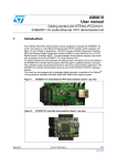
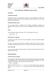
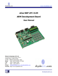
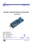
1
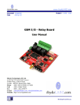
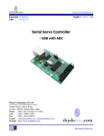
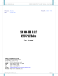
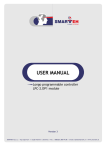
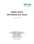
www.rhydolabz.com Document : Datasheet Date : 12-May-08 Model # : QSB - 120 LPC2129 Quick Start Board User Manual Rhydo Technologies (P) Ltd. (An ISO 9001:2000 Certified R&D Company) Golden Plaza, Chitoor Road, Cochin – 682018, Kerala State, India Phone : 0091- 484-2370444, 2371666 Cell : 0091- 99466 70444 Fax : 0091 - 484-2370579 E-mail : [email protected], [email protected] WebSite : http://www.rhydolabz.com We bring the world to you.. www.rhydolabz.com CONTENTS OVERVIEW FEATURES PACKAGE CONTENTS MICROCONTROLLER SPECIFICATION INTERFACE OVERVIEW POWER SUPPLY CLOCK SOURCE MICROCONTROLLER - PIN OUT PORT PINS – BERGE STRIP & ROUND MACHINE CUT CONNECTOR UNIVERSAL ASYNCHRONOUS RECEIVER TRANSMITTER (UART) JTAG CONNECTION CONTROLLER AREA NETWORK (CAN) INTERFACE SETTING UP QsLPC2129 PROGRAMMING STEPS We bring the world to you.. www.rhydolabz.com The QsLPC2129 is a Low Cost Development Board that can be used to quickly evaluate and demonstrate the capabilities of NXP LPC 2129 microcontroller. The board is designed to work as a header board with access to all pins for external connection. The board consists of a base board and a header board with microcontroller. Ideally suitable for development purposes. QsLPC2129 FEATURES • Compact and Ready to use design • Professional EMI/RFI Complaint PCB Layout Design for Noise Reduction • High Quality Two layer PTH PCB BASE BOARD FEATURES • Supports LPC2132/38/48* Header Boards • Includes LPC2129 (with in-built CAN peripheral ) Header Board • No separate programmer required (On-Chip Boot loader) • No Separate power adapter required (USB power source) • Screw terminal for External power Supply • Power Supply range of 7V to 20V • RS-232 Interface for direct connection to PC’s serial port (UART 0) • On Board RS 232 to TTL Converter (UART 1) • On Board Power LED Indicator • On Board LED Connected via Jumper to port pin • On Board Reset button • All Port Pins available at Berge Strip and at Round Machine-cut female connector • On Board JTAG Connector for Debugging/Programming • On Board CAN Transceiver • On Board CAN Bus Connector We bring the world to you.. www.rhydolabz.com • Can be used as header board for developing applications • Power Supply Reverse Polarity Protection • On Board DB9 Connector • On Board USB Connector • On Board 1 Amp Voltage Regulator • On Board Connector for regulated 3V3 output HEADER BOARD FEATURES • • Includes NXP LPC 2129 Microcontroller with in-built CAN peripheral • On Board Power LED Indicator • On Board JTAG Jumper • On Board 10 MHz Crystal Oscillator • On Board 32.768 KHz Crystal for RTC • On Board 3.3V Regulator • On Board 1.8V Regulator • On Board Power Supply de-Coupling Capacitors • All Port Pins available at Berge Strip • Header Module can be removed for developing your circuit (Pin Out in LPC 2129) QsLPC2129 PACKAGE INCLUDES Fully Assembled and Tested QsLPC2129 Development board Software CDROM with Schematic Programming Software Sample Hex Code Example Codes We bring the world to you.. Easy t www.rhydolabz.com LPC 2129 SPECIFICATION NXP LPC 2129 with 10 MHz Crystal Oscillator (With Boot loader Software) High Performance 32-bit ARM7TDMI-S™ CPU 256 KB Programmable Flash Memory provides a minimum of 100,000 erase/write cycles and 20 years of data retention. 16 KB Data Memory (SRAM) In-System/In-Application Programming (ISP/IAP) via on-chip boot- loader software. Flash programming takes 1 ms per 512 byte line. Single sector or full chip erase takes 400ms. EmbeddedICE-RT interface enables breakpoints and watch points. Two interconnected CAN interfaces with advanced acceptance filters Four channel 10-bit A/D converter with conversion time as low as 2.44 us. Multiple serial interfaces including two UARTs , Fast I2 C (400 kbits/s) and two SPIs 60MHz maximum CPU clock available from programmable on-chip Phase-Locked Loop Vectored Interrupt Controller with configurable priorities Two 32-bit Timers. Four Capture and four Compare channels. PWM unit with six output pins. Real-time clock. Watch Dog Timer Up to forty-six 5V tolerant general purpose I/O pins. Up to nine edge or level sensitive external interrupt pins. On-chip crystal oscillator with an operating range of 1MHz to 30MHz. Two low power modes - Idle and Power-down. Processor wake-up from Power-down mode via external interrupt. Individual enable/disable of peripheral functions for power optimization. CPU operating voltage range of 1.65V to 1.95V and I/O power supply range of 3.0V to 3.6V We bring the world to you.. www.rhydolabz.com INTERFACE OVERVIEW USB Power Interface Power Select (USB or DC) External Power Supply (7V-20V) NXP LPC2129 Header Module Berge Strip (Female) JTA G Jumper MAX3232 CA N Transceiver JTA G Connector Serial Port (COM 0) 3V3 Out CAN Tx, Rx (LPC2129) COM1 Round Machine Cut Female con. RESET Switch We bring the world to you.. www.rhydolabz.com POWER SUPPLY QsLPC2129 Board has two power supplies; you can choose one of the following ways to supply power (1) Through a Screw Terminal (7V - 20V External DC Power Supply) (2) Through the motherboard USB port Note: For power selection, the appropriate jumper (J4) must be in position. The Power Supply circuit is given below: +5 K5 DVCC D+ GND 1 2 3 4 J3 PWR USB PWR DC JUMPER3 USB +5 1 U4 LD1117S33 LM7805 Vin Vout 3 5V Vin 3.3V Vout 1 2 CONN 2PIN C14 C17 47MF/16V K3 2 1 1N4007 3 1 2 1 U3 2 12VDC D2 GND K2 C9 0.1MF C13 10MF C10 0.1MF R13 470R 10MF D3 LED GND CLOCK SOURCE QsLPC2129 board uses: 10/12 MHz Crystal as the MCU clock source We bring the world to you.. www.rhydolabz.com HEADER BOARD - PIN OUT U1 3.3V R11 4K7 J1 ISP P0.0 P0.1 P0.2 P0.3 P0.4 P0.5 P0.6 P0.7 P0.8 P0.9 P0.10 P0.11 P0.12 P0.13 P0.14 P0.15 P0.16 P0.17 P0.18 P0.19 P0.20 P0.21 P0.22 P0.23 RST 1 2 3 4 5 6 7 8 9 10 11 12 13 14 15 16 17 18 19 20 21 22 23 24 25 P0. 0 P0. 1 P0. 2 P0. 3 P0. 4 P0. 5 P0. 6 P0. 7 P0. 8 P0. 9 P0. 10 P0. 11 P0. 12 P0. 13 P0. 14 P0. 15 P0. 16 P0. 17 P0. 18 P0. 19 P0. 20 P0. 21 P0. 22 P0. 23 RESET P0. 24 P0. 25 CANTX P0. 27 P0. 28 P0. 29 P0. 30 P1. 16 P1. 17 P1. 18 P1. 19 P1. 20 P1. 21 P1. 22 P1. 23 P1. 24 P1. 25 P1. 26 P1. 27 P1. 28 P1. 29 P1. 30 P1. 31 V5. 0 GND 50 49 48 47 46 45 44 43 42 41 40 39 38 37 36 35 34 33 32 31 30 29 28 27 26 P0.24 P0.25 CAN TXD P0.27 P0.28 P0.29 P0.30 P1.16 P1.17 P1.18 P1.19 P1.20 P1.21 P1.22 P1.23 P1.24 P1.25 RTCK TDO TDI TCK TMS TRST 5V GND LPC2 129 MODULE C13 10 MF C3 0.1 MF PORT PINS – BERGE STRIP & ROUND MACHINE CUT CONNECTOR The QsLPC2129 board has all port pins available at Berge strip and at round machine cut female connector. The connection is as given below. K7 1 2 3 4 5 6 7 8 9 10 11 12 13 14 15 16 17 18 19 20 21 22 23 24 25 CONN 25PIN K8 P0.0 P0.1 P0.2 P0.3 P0.4 P0.5 P0.6 P0.7 P0.8 P0.9 P0.10 P0.11 P0.12 P0.13 P0.14 P0.15 P0.16 P0.17 P0.18 P0.19 P0.20 P0.21 P0.22 P0.23 RST 1 2 3 4 5 6 7 8 9 10 11 12 13 14 15 16 17 18 19 20 21 22 23 24 25 CONN 25PIN K9 K10 1 2 3 4 5 6 7 8 9 10 11 12 13 14 15 16 17 18 19 20 21 22 23 24 25 CONN 25PIN P0.24 P0.25 CAN TX P0.27 P0.28 P0.29 P0.30 P1.16 P1.17 P1.18 P1.19 P1.20 P1.21 P1.22 P1.23 P1.24 P1.25 RTCK P1.26 TDO P1.27 TDI P1.28 TCK P1.29 TMS P1.30 TRST P1.31 5V GND 1 2 3 4 5 6 7 8 9 10 11 12 13 14 15 16 17 18 19 20 21 22 23 24 25 CONN 25PIN We bring the world to you.. www.rhydolabz.com SETTING UP Qs LPC 2129 Power the development board with a USB Cable Make sure that the Power-On LED is ON and Jumper in proper position. Connect the RS-232 Cable to the COM port of your computer. Connect the other end to the Serial Port of your development board We bring the world to you.. www.rhydolabz.com PROGRAMMING STEPS (The Quick Start board uses COM0 for programming) 1. Configure LPC Flash Utility software at the PC side a. Browse your hex file here. b. Select your COM port and Set baud rate (9600) here. c. Disable DTR/RTS for Reset and boot loader selection. 2. Connect system serial port to COM port of Qs LPC 2129 . 3. Put jumper on ISP 4. Click “Read Device ID” 5. The software prompts you to reset the quick start board. 6. Press Reset button and press OK 7. Wait till Device Id is shown 5. Click “Upload to Flash” button in the flash utility software and wait till the programming is over. 6. Remove jumper on ISP 7. Now Reset the quick start board. N.B: If any interface is done using Port0 2 and 3 pins ( P0.2,P0.3 ), the pins have to be externally pulled-up to 3.3V using 4K7 resistor (since these pins are open-drain). Note: This product has been tested and certified by the company before shipping. Removing or replacing the components from the PCB could damage the product. In this case, the company won’t be liable for the damages caused and no replacement/ refunding are entertained. No warranty or guarantee is provided on this product, unless it’s specified. We bring the world to you.. www.rhydolabz.com TECHNICAL SUPPORT If you are experiencing a problem that is not described in this manual, please contact us. Our phone lines are open from 9:00 AM – 5.00 PM (Indian Standard Time) Monday through Saturday excluding holidays. Email can be sent to [email protected] LIMITATIONS AND WARRANTEES This product is intended for personal or lab experimental purpose and in no case should be used where it harmfully effect human and nature. No liability will be accepted by the publisher for any consequence of its use. Use of the product software and or hardware is with the understanding that any outcome whatsoever is at the users own risk. All products are tested for their best performance before shipping, still rhydoLABZ is offering One year Free service warranty ( Components cost + Shipping cost will be charged from Customer ) DISCLAIMER Copyright © Rhydo Technologies (P) Ltd All rights are reserved. Reproduction in whole or in part is prohibited without the prior written consent of the copyright owner. The information presented in this document does not form part of any quotation or contract, is believed to be accurate and reliable and may be changed without notice. Rhydo Technologies (P) Ltd. (An ISO 9001:2000 Certified R&D Company) Golden Plaza, Chitoor Road, Cochin – 682018, Kerala State, India Phone : 0091- 484-2370444, 2371666 Cell : 0091- 99466 70444 Fax : 0091 - 484-2370579 E-mail : [email protected], [email protected] WebSite : http://www.rhydolabz.com We bring the world to you..