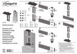
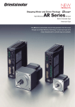
1
Hollow Rotary Actuator
DG Series
Built-In Controller Type
Pulse Input Type
The new DG Series uses the highly efficient
and energy saving
AR Series as the motor of the hollow rotary actuator.
In addition to the pulse input type, a highly functional built-in controller type that supports
and increases system configuration flexibility is also available.
Hollow Rotary Actuator
DG Series
Hollow rotary actuators are now even easier to use.
In the DG Series, an
AR Series stepping motor and driver package is used on a
large diameter hollow rotary actuator.
Functionality for easier control of the rotary actuator mechanism is provided along with
better connectivity with switches, PLC, touch panels or FA networks.
Oriental Motor has responded to customer feedback regarding conventional models to
create a new actuator that is easier to use.
■ DG Series Renewed Appeal
High Efficiency and Energy Saving
A closed loop
AR Series stepping motor and driver
package has been adopted as the motor. This creates a
more efficient and energy saving product compared with
conventional models.
High Function Driver Increases System
Configuration Flexibility
A system common with the AR Series is now used for
control, and functions for easier use of the actuator have
been added.
Both a built-in controller type driver that can be connected
to I/O, Modbus (RTU) and FA networks as well as a pulse
input type driver are available.
Flexibility for connecting with host systems has also been
increased.
2
Contents
Actuator Features ……………p. 4
■ Same Actuator Excellence as Conventional Models
Large-Diameter Hollow Output Table
Lineup ………………………p. 5
Motor Features ………………p. 6
Driver Features ………………p. 7
Frame size □60 mm □85 mm □130 mm □200 mm
How to Read
Specifications Table ……… p. 11
High Torque and High Rigidity
System Configuration …… p. 12
Product Line ……………… p. 14
Direct Coupling Possible
High Accuracy and Quick Positioning
Specifications and
Characteristics …………… p. 15
Dimensions ……………… p. 21
Connection and Operation … p. 26
Combination List ………… p. 40
Accessories ……………… p. 41
3
Actuator Features
Contributes to Easier Equipment Design and Quicker Deliveries.
DG60 Structure
Output Table
Deep-Groove Ball Bearing
DG85, 130, 200 Structure
Gear
Output Table
Output Table
(With integrated
cross-roller bearings)
Pinion
● DG60 has a deep-groove
ball bearing.
Motor
Cross-Roller Bearing
Actuator with High Strength, Accuracy and Reliability
High Power and High Rigidity
Direct Coupling for Higher Reliability
The hollow output table is integrated with a high rigidity crossroller bearing✽. This structure improves permissible thrust load
and moment load while maintaining high torque.
Equipment tables and arms can be installed directly on the output table.
This saves you the hassle and cost of designing an installation mechanism,
arranging necessary mechanism parts, adjusting the belt tension, etc., when
mechanical components such as a belt and pulley are used for installation.
✽ Excludes the DG60
<Rigidity>
The output table uses a cross-roller bearing (85, 130, and 200 mm
frame size) or 2 deep-groove ball bearings (60 mm frame size). The
permissible moment load increases as the frame size increases, but
the displacement caused by the moment load decreases.
Displacement [μm]
Displacement [μm]
Arm
200
150
100
DG130
High Rigidity
(Small displacement)
Distance from Center of F [N]
Rotation L [mm]
Displacement at Distance L=200 mm from Center of Rotation
300
DG60
High Permissible Moment
250
DG85
50
0
0
20
DG200
40
60
80
100
Moment Load [N·m]
High Positioning Accuracy with Non-Backlash
"Home Sensor Set" is Available as an Accessory
● Non-Backlash
● Repetitive Positioning Accuracy ±15 sec
● Lost Motion 2 arc minutes
Since the sensor set comes with all the parts required for the return-to-home operation, you
will spend less time designing, fabricating and procuring parts related to sensor installation.
Note
The repetitive positioning accuracy is measured at a constant
DG130 Sensor Installation Example
temperature (normal temperature) under a constant load.
Large-Diameter, Hollow Output Table Makes Simple Wiring and Piping Possible
Shield Plate
DG60
DG85
DG130
DG200
Frame Size
mm
Diameter of
Hollow Section mm
60
85
130
200
ϕ28
ϕ33
ϕ62
ϕ100
Example: DG200
4
□200 mm
The large diameter hollow hole (through-hole) helps reduce the
complexity of wiring and piping, thus simplifying your equipment design.
ϕ100 mm
Sensor
Application
● Applications Subject to Changing Load Inertia
● Applications Where a Moment Load is Applied
● Optical Applications Using the Hollow Hole
● High Positioning Accuracy Applications
● High Positioning Accuracy Applications Using the Hollow Hole
● Air Adsorption Applications Using the Hollow Hole
Lineup
Actuator
Frame Size
Product
Electromagnetic
Brake
Driver
Power Supply
Voltage
Diameter
of
Permissible
Hollow
Torque
Section
[N·m]
[mm]
Permissible Moment Load
Permissible Thrust Load
[N·m]
20
40
60
[N]
80
1000
2000
3000
DG60
Built-in Controller
−
60 mm
Pulse Input
DG85
Built-in Controller
Pulse Input
Built-in Controller
Single-Phase 100-120 VAC
Single-Phase 200-240 VAC
Pulse Input
Single-Phase 100-115 VAC
Single-Phase 200-230 VAC
Three-Phase 200-230 VAC
Built-in Controller
Single-Phase 100-120 VAC
Single-Phase 200-240 VAC
Pulse Input
Single-Phase 100-115 VAC
Single-Phase 200-230 VAC
Three-Phase 200-230 VAC
DG200
2
100
ϕ33
2.8
10
500
ϕ62
12
50
2000
ϕ100
50
100
4000
Single-Phase 200-240 VAC
●
130 mm
0.9
Single-Phase 100-120 VAC
Single-Phase 100-115 VAC
Single-Phase 200-230 VAC
Three-Phase 200-230 VAC
DG130
ϕ28
24 VDC
−
85 mm
200 mm
24 VDC
●
5
Motor Features
AR Series Now Used.
High Reliability Plus High Efficiency.
Excellent Characteristics Unique to Stepping Motors
User-Friendly and Easy, Highly
Accurate Positioning
High response
Stepping motors provide convenient
means to ensure highly accurate
positioning because they synchronize
themselves with commands without
requiring feedback.
The motor operates synchronously
with pulse commands to achieve high
response.
There's no time lag in operation following
a pulse command.
High Reliability Due to Oriental Motor's Unique Closed Loop Control
Adoption of a Rotor Position
Detection Sensor (Resolver)
Continues Operation Even with Sudden
Load Fluctuation and Sudden Acceleration
Alarm Signal Output in Case
of Abnormality
●Because the sensor is compact and
slim, the overall length of the motor
has been reduced.
Operates synchronously with commands
using open loop control during normal
conditions. In an overload condition,
changes immediately to closed loop
control to correct the position.
If an overload is applied continuously,
an alarm signal is output. When the
positioning is complete, an end signal is
output. This ensures the same level of
reliability achieved by a servo motor.
Input Counter
Deviation Counter
Rotor Position
Counter
Output Component
●Because an encoder cable is not
necessary, the motor and driver can
be connected
with just 1
cable.
Excitation Sequence Control
Input Signal
●Performance such as heat resistance
and vibration resistance is better than
with regular optical encoders.
Normal
● Motor runs in open loop mode
like a stepping motor.
Motor
Sensor
Overload Condition
The closed loop mode is engaged to
maintain the positioning operation.
Rotor Position Detection Sensor
Continuous Operation Possible Due to Lower Heat Generation from Higher Efficiency
Lower Heat Generation
Power Consumption: 66% Less Than Conventional
Model due to Energy-Saving Features✽
Heat generation by the motor has been significantly reduced through higher efficiency.
● Power Consumption
800
● Motor Surface Temperature during Same
Operation Conditions
Power Consumption [kWh/Year]
● Temperature Distribution by Thermography
120
Temperature [˚C]
100
AR66AC-◇
Conventional
Model
Comparison under same conditions.
80
60
40
AR66AC-◇
Conventional Model
20
0
0
20
40
60
80
100
Time [min]
120
140
160
180
700
600
500
400
Power Consumption
66% Reduction
300
200
100
0
Conventional Model
AR66AC-◇
CO2 Emissions: 66% Less Than
Conventional Model✽ (Oriental Motor
comparison)
✽ Speed: 1000 r/min, Load Factor: 50%
Operating Time: 24 hours of operation (70% operating,
25% standing by, 5% standstill), 365
days/year
6
Driver Features
Connectable with Various Host Systems.
2 Driver Types Selectable by System Configuration
You can select from 2 driver types for the DG Series, depending on your host system.
Built-in Controller Type
● When Controlling with
I/O
Power
Supply
Unit
CPU
Unit
I/O
Unit
Pulse Input Type
● When Controlling with
Serial Communication
Power
Supply
Unit
CPU
Unit
● When Controlling from a
Touch-Screen Panel Computer
Serial
Communication
Unit
Power
Supply
Unit
Touch-Screen Panel
Computer
CPU
Unit
Positioning
Unit
Pulse Input
① I/O
② Modbus (RTU)
② Modbus (RTU)
Type that executes
operation by inputting
pulses into the driver.
Type where the operating data is set in the driver, and the operating
Control the motor using
a positioning unit (pulse
generator) that you have
obtained yourself.
data is selected and executed from the host system.
Host system connection and control is performed with ① I/O, ②
Modbus (RTU)/RS-485 or ③ FA network.
How to Connect a Built-In Controller Type
① I/O
Because the positioning unit (pulse generator) function is built in to the driver, you can build an operation system using I/O by directly
connecting to a switch box or PLC. Because a positioning unit is not necessary on the PLC side, space is saved and the system is simplified.
● Example of Using a Switch Box
● Example of Using PLC
● Example of Using PLC and a Touch Panel
Touch Panel
STRT
STOP
CCW
CW
STRT
STOP
CCW
CW
I/O Unit
I/O Unit
CPU Unit
CPU Unit
Power
Supply Unit
Power
Supply Unit
Switch Box
Because operating data is set in the driver, the
actuator can be started and stopped simply by
connecting a switch you have on hand. Control
can be performed easily without using PLC.
When using PLC, you can build an operation
system by connecting directly to an I/O unit.
Because a positioning unit is not necessary on
the PLC side, space is saved and the system is
simplified.
Normally, the actuator is started and stopped with I/O.
Changing the operating data settings and displaying the
monitors and alarms is performed with the touch panel
using Modbus (RTU) communication. When there is a lot of
setup work, changes can be easily performed on the touch
panel, and the burden of creating ladders is reduced.
② Modbus (RTU)/RS-485
Operating data and parameters can be set and operation commands can be input using RS-485
communication. Up to 31 drivers can be connected to each serial communication unit. Also, there
is a function that enables the simultaneous start of multiple axes. The protocol supports Modbus
(RTU), enabling connection with devices such as touch-screen panel computers and PCs.
7
Driver Features
Built-In Controller Type
Because the driver has the information necessary for
actuator operation, the burden on the host PLC is reduced.
The system configuration when using multi-axis control has
been simplified.
Settings are configured using a control module (sold
separately), data setting software or RS-485 communication.
Basic Setting
(Factory Setting)
Operation Data Setting
Parameter Changing
Driver
Data Setting
Test Operation
Actuator
Control Module
(OPX-2A)
Alarm History
Parameter Changing
or
Operation Types
Connection Cable
Monitoring
In the built-in controller type, the operating speed
and traveling amount of the actuator are set
with operating data, and operation is performed
according to the selected operating data.
Data Setting Software (MEXE02)
Data Copying
● Settings using RS-485 communication are also available.
Item
Content
I/O Control
Network converter connection
Modbus RTU protocol connection
Position Command Setting with operating data number Command range for each point: −8388608 to 8388607 [step] (Setting Unit: 1
Input
[step])
Speed Command Input Setting with operating data number Command Range: 0 to 1000000 [Hz] (Setting Unit: 1 [Hz])
Control Method
Common
Acceleration/
Deceleration
Command Input
RS-485 Communication
Set with the operating data number or parameter.
You can select acceleration/deceleration rate [ms/kHz] or acceleration/deceleration time [sec].
Command Range: 0.001 to 1000.000 [ms/kHz] (Setting Unit: 0.001 [ms/kHz])
0.001 to 1000.000 [sec] (Setting Unit: 0.001 [sec])
Acceleration/
Velocity filter, movement average filter
Deceleration Processing
2-Sensor Mode
A return-to-home operation that uses a limit sensor (+LS, −LS).
Return3-Sensor Mode
A return-to-home operation that uses a limit sensor and home sensor.
Return-to-Home
To-Home
Modes
A function where P-preset is input at the desired position to confirm the home position.
Operation
Position Preset
You can set the home position to the desired value.
Number of
64 points (No. 0 to 63)
Positioning Points
Incremental mode (Relative positioning)
Operating Modes
Absolute mode (Absolute positioning)
Independent Operation
A PTP (Point to Point) positioning operation.
A multistep speed-change positioning operation that is linked with operating data.
Linked Operation
Operation Functions
Positioning
A positioning operation with a timer that is linked with operating data.
Linked Operation 2
Operation
The timer (dwell time) can be set from 0 to 50.000 [sec]. (Setting Unit: 0.001 [sec])
Operating Data Selection Method
Start Methods
Direct Method (Direct positioning)
Starts the positioning operation when Start is input after selecting M0 to M5.
Starts the positioning operation with the operating data number set in the
parameters when MS0 to MS5 is input.
Starts the positioning operation.
Starts the positioning operation in sequence from operating data No. 0 each
time SSTART is input.
Sequential Method (Sequential
positioning)
Continuous Number of Speed Points 64 points (No. 0 to 63)
Operation Speed Change Method Change the operating data number.
JOG Operation
Execute regular feed by inputting +JOG or −JOG.
Other
When the motor position is moved by an external force while the motor is in a non-excitation state, it automatically
Operations Automatic Return
Operation
returns to the position where it originally stopped.
Absolute Backup
You can build an absolute system by using a battery (accessory).
●Push-motion operation cannot be used with this product.
Positioning Operation
● Independent Operation
● Linked Operation
Operating Data
No. 0
Starting
Command
● Linked Operation 2
Speed
Speed
Operating Data Operating Data
No. 1
No. 0
Operating Data
No. 1
Time
Starting
Command
Operating Data
No. 0
Time
Time
Operating Data
No. 1
Starting
Command
8
<Start Methods>
Dwell
Time
Speed
● Operating Data
Selection Method
● Direct Positioning
● Sequential
Positioning
Return-To-Home Operation
Continuous Operation
● 2-Sensor Mode
−LS
+Side
● JOG Operation (Test operation)
+Direction
Motor Operation
−Direction
+LS
−VR
−VS
Time
● Automatic Return Operation
M0∼M5 Input
−VS
−VR
−Side
Other Operations
FWD Input
● Equipped with a sequence for return-tohome operation that reduces the burden of
the host master and the hassle of creating a
ladder.
RVS Input
● 3-Sensor Mode
−LS
+Side
HOMES
−Side
+LS
−VR
−VS
−VS
−VR
● Position Preset
Main Function
Function
Motor Resolution Setting
Function ✽1
Group Send Function
(RS-485 communication)
Round Function
Content
The motor resolution can be changed by the driver without the
mechanically operated speed reduction mechanism.
A desired setting can be made from 100 to 10000 [P/R].
How to obtain the resolution on the actuator
Electronic gear B
[P/R]
1000×
× 18
Electronic gear A (Gear ratio)
You can configure a group of multiple axes connected using RS-485
communication, and send commands by group.
You can also perform simultaneous start and simultaneous operation for
multiple axes.
0 axis Start the positioning operation
Operation Commands
(RS-485 communication)
Actuator Operation for
Axis 1 (Driven axis)
Actuator Operation for
Axis 1 (Driven axis)
When the command position is outside the setting value of the "round
setting range" parameter, this function returns the command position and
multiple rotation data to 0.
Because the multiple rotation data is also returned to 0, you can perform
position control even for continuous rotation operations in the same
direction that use the absolute backup system.
● When building an absolute system, the accessory (sold separately) battery is necessary.
This function stops the actuator when exceeding the mechanical limit.
Software
Overtravel
This function stops the actuator when exceeding the limit set by the software.
Depending on the setting, an alarm can also be output without stopping.
Stop Input
(External stop)
This function forcibly stops operation when there is an abnormality or
other issue. You can select instantaneous stop, deceleration stop, or all
windings off (actuator holding force is off) as the stopping method.
Alarm Code Output
You can output alarm codes that are occurring.
Alarm History
Even if the power is turned off, up to 10 alarms that have occurred can be
stored.
This can be used for troubleshooting.
Velocity Filter
This is used to make adjustments when a smooth start/stop or smooth
motion at low speed operation is required. Even for sudden operation
command changes, this function controls the speed changes of the
actuator to prevent them from becoming too large.
At 1024
Actuator Speed
Hardware
Overtravel
At 1
Time
Difference in Characteristics Due to Velocity Filter
Teaching Function✽1
You can perform teaching. Move the load to the target position, and store the position data at this time as the
positioning data.
I/O Monitoring ✽1
You can check the ON/OFF status of the I/O signals.
Waveform Monitoring ✽2
You can check the operating speed and I/O signals as a waveform.
●The MEXE02 data setting software can be downloaded from the Oriental Motor website. Oriental Motor can also provide a CD-ROM.
For details, please contact the nearest Oriental Motor sales office.
✽1 Can be performed with the separately-sold control module (OPX-2A) or data setting software (MEXE02).
✽2 Can be performed with the data setting software (MEXE02).
9
Driver Features
Pulse Input Type
You can use the separately-sold control
module and data setting software to
perform operations according to your
needs, such as changing the parameters,
displaying the alarm history, and
performing various types of monitoring.
Basic Setting
(Factory Setting)
Extended Settings
Test Operation
Driver
Control Module
(OPX-2A)
Actuator
Alarm History
Parameter Changing
Monitoring
or
Connection Cable
Data Copying
Data Setting Software (MEXE02)
Main Additional Functions Available with Extended Settings
Item
Selection of Pulse Input Mode
Overview
You can select the 1-pulse input or 2-pulse input (negative logic) mode.
●
●
In addition to the normal settings, you can set phase difference input.
· 1-pulse input mode (positive logic/negative logic)
· 2-pulse input mode (positive logic/negative logic)
· Phase difference input (1-multiplication/2-multiplication/4-multiplication)
−
●
You can select the resolution with the function switches (D0, D1, CS0, CS1).
●
●
Resolution Setting
You can change the value of the electronic gear corresponding
to each function switch (D0, D1, CS0, CS1).
−
●
You can change the running current setting with the current setting switch (CURRENT).
●
●
Running Current Setting
You can change the value corresponding to each of 0 to F (16 levels) for
the current setting switch (CURRENT).
−
●
Standstill Current Ratio Setting
You can set the ratio of the standstill current relative to the running current.
−
●
Motor Rotational Coordinates Setting
You can set the rotational coordinates for the motor.
−
●
The input signal for the excitation of the motor.
●
●
You can set the C-ON input logic for when the power supply is input.
−
●
You can set whether or not to return to the excitation position (deviation 0 position) during
all windings on.
−
●
All Windings On Signal (C-ON input)
Return to Excitation Position Operation
during All Windings On
Enable/Disable
Alarm Code Signal Enable/Disable
Set to output the code when an alarm occurs.
−
●
End Output Signal Range Setting
You can change the End output signal range.
−
●
End Output Signal Offset
You can offset the End output signal value.
−
●
A-/B-Phase Output
You can use for motor position verification.
●
●
Timing Output Signal
This is output each time the motor rotates 7.2˚ (0.4˚ for the output table).
●
●
Applies a filter to the operation command to control the motor action.
●
●
You can change the value corresponding to each of 0 to F (16 levels) for the setting switch.
−
●
You can set to suppress resonant vibration during rotation.
−
●
You can set to suppress vibration during acceleration, deceleration and stopping.
−
●
Adjusts the position and speed loop gain.
−
●
Adjusts the speed integration time constant.
−
●
Sets the damping control vibration frequency.
−
●
Sets whether to enable or disable damping control.
−
●
You can select the motor excitation position for when the power is turned on.
−
●
You can select whether to use symbols or an absolute value display for the speed display
of the control module.
−
●
You can set the geared motor gear ratio for the speed monitor. (The gear ratio for the DG
Series is 1:18)
−
●
Velocity Filter Setting
Vibration Suppression Function for
Normal Mode
Gain Adjustment for Current Control
Mode ✽
Selection of Motor Excitation Position at
Power On
Control Module Setting
●The MEXE02 data setting software can be downloaded from the Oriental Motor website. Oriental Motor can also provide a CD-ROM.
For details, please contact the nearest Oriental Motor sales office.
✽Except when you want to further reduce heat generation or noise, using normal mode is recommended.
10
Basic Extended
Setting Settings
Lineup
How to Read Specifications Table
■Built-In Controller Type
Product Name
Motor Type
Output Table Supporting Bearing
Permissible Torque
③
Inertia
④
Permissible Speed
Gear Ratio
Resolution
⑨
Power-Supply
Input
Maximum Holding Force
J: kg·m2
Power ON
N·m Power OFF
Electromagnetic Brake
Degree of Protection
1.8
12
0
0
−
12
The resolution can be set from 1800 to 180000 P/R by using parameters.
Single-phase 100-120 VAC, single-phase 200-240 VAC −15 to +6% 50/60 Hz
−
−
2.4
3.6
1.5
2.3
24 VDC±5% 0.5A
−
24 VDC±5% 0.25A
±15 (±0.004˚)
2 (0.033˚)
4 (0.067˚)
3 (0.05˚)
500
2000
10
50
0.015
0.015
0.030
Single Shaft, Electromagnetic Brake Type: IP40 (IP20 for motor connector)
Double Shaft: IP20
kg
2.65 [2.95]
Connection
and Operation
Combination
List
Accessories
⑪ Lost Motion
This is the difference in stopped angles achieved when the
output table is positioned to the same position in the forward
and reverse directions.
⑫ Angular Transmission Accuracy
This is the difference between the theoretical rotation angle
of the output table as calculated from the input pulse counter,
and the actual rotation angle.
⑬ Permissible Thrust Load
This is the permissible value of thrust load applied to the
output table in the axial direction.
⑭ Permissible Moment Load
When a load is applied to a position away from the center of
the output table, the output table receives a tilting force. The
permissible moment load refers to the permissible value of
moment load calculated by the eccentricity from the center by
the applied load.
⑮ Runout of Output Table Surface
This is the max. value of runout of the installation surface of
the output table when the output table is rotated under no
load.
⑯ Runout of Output Table Inner (Outer) Diameter
This is the max. value of runout of the inner diameter or outer
diameter of the table when the output table is rotated under no
load.
⑰ Parallelism of Output Table
This is the inclination of the installation surface of the output
table compared with the actuator installation surface on the
equipment side.
⑱ Degree of Protection
Based on IEC60529 and EN60034-5 (=IEC60034-5), dustresistance and waterproofing regarding the degree of
protection of the device is classified using a grade.
Dimensions
① Output Table Supporting Bearing
This is the type of the bearing used for the output table.
② Permissible Torque
This is the limit of mechanical strength of the speed reduction
mechanism. Make sure that the applied torque, including the
acceleration torque and load fluctuation, does not exceed the
permissible torque.
③ Inertia
This is the total sum of the rotor inertial moment of the motor
and the inertial moment of the speed reduction mechanism
converted to a moment on the output table.
④ Permissible Speed
This is the output table speed that can be tolerated by the
mechanical strength of the speed reduction mechanism.
⑤ Maximum Holding Torque (Power supply ON)
This is the maximum torque with which to hold the output
table in position if it stops while the power is still on.
⑥ Maximum Holding Torque (Power supply OFF)
This is the maximum torque with which to hold the output
table in position if it stops after the power has been cut off.
⑦ Maximum Holding Torque (Electromagnetic brake)
This is the maximum torque (with electromagnetic brake
only) with which to hold the output table in position using an
electromagnetic brake when it stops.
⑧ Resolution
Number of pulses needed to rotate the output table by one
rotation.
⑨ Power-Supply Input
The current value of the power-supply input is the max. input
current value for the driver. (The input current varies according
to the rotation speed.)
⑩ Repetitive Positioning Accuracy
This is a value indicating the degree of error that generates
when positioning is performed repeatedly to the same position
in the same direction.
1.17
Specifications and
Characteristics
⑱
200
18
Product Line
⑩
⑪
⑫
⑬
⑭
⑮
⑯
⑰
150620×10 -7
[189500×10 -7]
22092×10 -7
r/min
Voltage and Frequency
24 VDC
Input Current A Single-Phase 100-120 VAC
Single-Phase 200-240 VAC
Control Power Supply
Electromagnetic Brake Power-Supply Input
Repetitive positioning accuracy
sec
Lost Motion
arc minute (degrees)
Angular Transmission Accuracy
arc minute (degrees)
Permissible Thrust Load
N
Permissible Moment Load
N·m
Runout of Output Table Surface
mm
Runout of Output Table Inner (Outer) Diameter
mm
Parallelism of Output Table
mm
Mass of Actuator Unit
2.8
System
Configuration
⑤
⑥
⑦
⑧
N·m
130 mm
DG130R-ARAAD-◇
DG130R-ARBAD-◇
DG130R-ARMAD-◇
Motor for AR Series
Cross-Roller Bearing
12
How to Read
Specifications Table
①
②
85 mm
DG85R-ARAAD-◇
DG85R-ARBAD-◇
−
Features
Frame Size
Single Shaft
Single-Phase
Double Shaft
100-120 VAC
Electromagnetic Brake Type
11
■System Configuration
●Built-In Controller, AC Power-Supply Input Electromagnetic Brake Type
An example of a configuration using I/O control or RS-485 communication is shown below.
✽1 Not supplied.
✽2 To be provided by the customer as necessary.
Accessory (Sold separately)
The cables used in the EMC Directive evaluation.
When extending the distance between the actuator and
the driver without using an included connection cable
When extending the distance between the actuator and
the driver using an included connection cable
or
(For electromagnetic brake)
(For electromagnetic brake)
Connection Cable Sets
Flexible Connection Cable Sets
( ➜ Page 47)
Extension Cable Sets
Flexible Extension Cable Sets
( ➜ Page 47)
Accessory (Sold separately)✽2
Control Module
( ➜ Page 41)
Data Setting Software
Data Setting Software
Communication Cable
( ➜ Page 42)
or
MEXE02
( ➜ Page 42)
To USB
Port
24 VDC Power
Supply
for Control ✽1
Computer✽1
DG Series
Driver
Actuator
(For RS-485
communication)
For Electromagnetic
Brake
For Motor
Host System✽1
Sensor✽1
The product comes with a 1 m, 2 m or 3
m cable (for motor and electromagnetic
brake).
AC Power Supply
(Main power supply)
Accessory (Sold separately)
Installation Pedestal
for DG Series
( ➜ Page 51)
Battery Set
( ➜ Page 50)
Home Sensor Set
( ➜ Page 43)
RS-485
Communication Cable
( ➜ Page 50)
● User's Manuals are available that describe the operation methods for these products. For details, please contact the nearest Oriental Motor sales office, or download from the Oriental
Motor website. http://www.orientalmotor.eu
●System Configuration Example
DG Series
DG130R-ARMAD-1
Sold Separately
Installation Pedestal
Home Sensor Set
for DG Series
MDG130A
PADG-SB
● The system configuration shown above is an example. Other combinations are available.
12
An example of a single-axis system configuration with the SG8030J controller is shown below.
✽Not supplied.
Lineup
●Pulse Input, AC Power-Supply Input Electromagnetic Brake Type
Accessory (Sold separately)
When extending the distance between the actuator and
the driver without using an included connection cable
Features
The cables used in the EMC Directive evaluation.
When extending the distance between the actuator and
the driver using an included connection cable
(For electromagnetic brake)
How to Read
Specifications Table
or
(For electromagnetic brake)
Connection Cable Sets
Flexible Connection Cable Sets
( ➜ Page 47)
Extension Cable Sets
Flexible Extension Cable Sets
( ➜ Page 47)
Control Module
( ➜ Page 41)
or
Data Setting Software
Data Setting Software
Communication Cable
( ➜ Page 42)
MEXE02
( ➜ Page 42)
Product Line
To USB
Port
Computer✽
DG Series
Controller (Sold separately)
Driver
Actuator
24 VDC Power
Supply✽
For Motor
Connection
and Operation
Controller
( ➜ Page 51)
The product comes with a 1 m, 2 m or 3
m cable (for motor and electromagnetic
brake).
AC Power Supply
(Main power supply)
Combination
List
Accessory (Sold separately)
Home Sensor Set
( ➜ Page 43)
General-Purpose Cable
( ➜ Page 49)
Connector - Terminal Block
Conversion Unit
( ➜ Page 49)
Accessories
or
Installation Pedestal for DG
Series
( ➜ Page 51)
Dimensions
Programmable
Controller✽
For Electromagnetic
Brake
Specifications and
Characteristics
For Electromagnetic
Brake
24 VDC Power Supply✽
System
Configuration
Accessory (Sold separately)
● User's Manuals are available that describe the operation methods for these products. For details, please contact the nearest Oriental Motor sales office, or download from the Oriental
Motor website. http://www.orientalmotor.eu
●System Configuration Example
DG Series
Controller
DG130R-ARMA-1
SG8030J-D
Sold Separately
Installation Pedestal
Home Sensor Set
for DG Series
MDG130A
PADG-SB
Connector – Terminal Block
Conversion Unit (1 m)
CC36T10E
● The system configuration shown above is an example. Other combinations are available.
13
■Product Number Code
DG 130 R - AR A C D - 1
①
②
③
④
⑤ ⑥ ⑦
⑧
① Series Name DG: DG Series
② Frame Size 60: 60 mm 85: 85 mm 130: 130 mm 200: 200 mm
③
Output Table Supporting Bearing Type Blank: Deep-Groove Ball Bearing
R : Cross-Roller Bearing
④ Motor Type AR: Motor for AR Series
⑤
Motor Shaft Configuration A: Single Shaft B: Double Shaft
M: Electromagnetic Brake Type
Power-Supply Input Built-In Controller Type
A : Single-Phase 100-120 VAC C: Single-Phase 200-240 VAC
K : 24 VDC
⑥
Pulse Input Type
A : Single-Phase 100-115 VAC C: Single-Phase 200-230 VAC
S : Three-Phase 200-230 VAC K: 24 VDC
⑦
Driver Blank: Pulse Input Type
D: Built-In Controller Type
⑧ Length of Cables (Included) 1: 1 m 2: 2 m 3: 3 m
■Product Line
●Built-In Controller Type
◇ DC Power-Supply Input
24 VDC
Product Name
DG60-ARAKD-◇
DG60-ARBKD-◇
●Pulse Input Type
◇ DC Power-Supply Input
24 VDC
Product Name
DG60-ARAK-◇
DG60-ARBK-◇
◇ AC Power-Supply Input
Single-Phase 100-120 VAC
Product Name
DG85R-ARAAD-◇
DG85R-ARBAD-◇
DG130R-ARAAD-◇
DG130R-ARBAD-◇
DG130R-ARMAD-◇
DG200R-ARAAD-◇
DG200R-ARBAD-◇
DG200R-ARMAD-◇
Single-Phase 200-240 VAC
Product Name
DG85R-ARACD-◇
DG85R-ARBCD-◇
DG130R-ARACD-◇
DG130R-ARBCD-◇
DG130R-ARMCD-◇
DG200R-ARACD-◇
DG200R-ARBCD-◇
DG200R-ARMCD-◇
◇ AC Power-Supply Input
Single-Phase 100-115 VAC
Product Name
DG85R-ARAA-◇
DG85R-ARBA-◇
DG130R-ARAA-◇
DG130R-ARBA-◇
DG130R-ARMA-◇
DG200R-ARAA-◇
DG200R-ARBA-◇
DG200R-ARMA-◇
Single-Phase 200-230 VAC
Product Name
DG85R-ARAC-◇
DG85R-ARBC-◇
DG130R-ARAC-◇
DG130R-ARBC-◇
DG130R-ARMC-◇
DG200R-ARAC-◇
DG200R-ARBC-◇
DG200R-ARMC-◇
Three-Phase 200-230 VAC
Product Name
DG85R-ARAS-◇
DG85R-ARBS-◇
DG130R-ARAS-◇
DG130R-ARBS-◇
DG130R-ARMS-◇
DG200R-ARAS-◇
DG200R-ARBS-◇
DG200R-ARMS-◇
● A number indicating the desired length of 1 (1 m), 2 (2 m) or 3 (3 m) for the cable included with the product is entered where the box ◇ is located within the product name.
Select a desired cable length from 1 m, 2 m and 3 m.
14
■Specifications
Product Name
60 mm
DG60-ARAKD-◇
DG60-ARBKD-◇
−
−
−
−
−
−
85 mm
−
−
DG85R-ARAAD-◇
DG85R-ARBAD-◇
−
DG85R-ARACD-◇
DG85R-ARBCD-◇
−
J: kg·m2
2.8
4324×10 -7
22092×10 -7
r/min
50
150620×10 -7
[189500×10 -7] ✽2
916400×10 -7
[955280×10 -7] ✽2
200
110
18
0.45
0
−
24 VDC±5%
1.3
−
−
−
−
kg
0.5
1.17
2.65 [2.95]✽2
9.5 [10.1]✽2
Connection
and Operation
● A number indicating the desired length of 1 (1 m), 2 (2 m) or 3 (3 m) for the cable included with the product is entered where the box ◇ is located within the product name.
✽ 1 The back shaft of the motor in the double shaft type is intended for installing a slit disk. Do not apply load torque, overhung load or thrust load to the back shaft of the motor.
✽ 2 The brackets [ ] indicate the specifications for the electromagnetic brake type.
✽ 3 If the wiring distance between the motor and driver is extended to 20 m min. using an accessory cable (sold separately), the 24 VDC±4% specification applies.
Note
● Depending on the driving conditions, a considerable amount of heat may be generated by the motor. Be sure to keep the temperature of the motor case at approximately 100˚C max.
● The repetitive positioning accuracy is measured at a constant temperature (normal temperature) under a constant load.
Dimensions
Single Shaft, Electromagnetic Brake Type: IP40 (IP20 for motor connector)
Double Shaft: IP20
Degree of Protection
Specifications and
Characteristics
100
2
0.030
0.030
0.050
1.8
12
36 [20]✽2
0
0
0
−
12
20
The resolution can be set from 1800 to 180000 P/R by using parameters.
Single-phase 100-120 VAC, single-phase 200-240 VAC −15 to +6% 50/60 Hz
−
−
−
2.4
3.6
5.9
1.5
2.3
3.7
24 VDC±5% 0.5 A
−
24 VDC±5% ✽3 0.25 A
24 VDC±5% ✽3 0.25 A
±15 (±0.004˚)
2 (0.033˚)
4 (0.067˚)
3 (0.05˚)
2 (0.033˚)
500
2000
4000
10
50
100
0.015
0.015
0.030
0.030
0.050
Product Line
Power ON
Maximum Holding
Power OFF
Force
N·m
Electromagnetic Brake
Resolution
Voltage and Frequency
24 VDC
Power-Supply Input
Input Current A Single-Phase 100-120 VAC
Single-Phase 200-240 VAC
Control Power Supply
Electromagnetic Brake Power-Supply Input
Repetitive Positioning Accuracy
sec
Lost Motion
arc minute
Angular Transmission Accuracy
arc minute
Permissible Thrust Load
N
Permissible Moment Load
N·m
Runout of Output Table Surface
mm
Runout of Output Table Inner (Outer) Diameter
mm
Parallelism of Output Table
mm
Mass of Actuator Unit
Cross-Roller Bearing
12
System
Configuration
Permissible Speed
Gear Ratio
N·m
Deep-Groove Ball Bearing
0.9
How to Read
Specifications Table
Inertia
200 mm
−
−
DG200R-ARAAD-◇
DG200R-ARBAD-◇
DG200R-ARMAD-◇
DG200R-ARACD-◇
DG200R-ARBCD-◇
DG200R-ARMCD-◇
Motor for AR Series
Motor Type
Output Table Supporting Bearing
Permissible Torque
130 mm
−
−
DG130R-ARAAD-◇
DG130R-ARBAD-◇
DG130R-ARMAD-◇
DG130R-ARACD-◇
DG130R-ARBCD-◇
DG130R-ARMCD-◇
Features
Frame Size
Single Shaft
Double Shaft ✽1
Single Shaft
Single-Phase
Double Shaft ✽1
100-120 VAC
Electromagnetic Brake Type
Single Shaft
Single-Phase
Double Shaft ✽1
200-240 VAC
Electromagnetic Brake Type
24 VDC
Lineup
●Built-In Controller Type
Combination
List
Accessories
15
●Pulse Input Type
Frame Size
Single Shaft
24 VDC
Double Shaft✽1
Single Shaft
Single-Phase
Double Shaft✽1
100-115 VAC
Electromagnetic Brake Type
Single Shaft
Single-Phase
Double Shaft✽1
200-230 VAC
Electromagnetic Brake Type
Single Shaft
Three-Phase
Double Shaft✽1
200-230 VAC
Electromagnetic Brake Type
Product Name
60 mm
DG60-ARAK-◇
DG60-ARBK-◇
−
−
−
−
−
−
−
−
−
85 mm
−
−
DG85R-ARAA-◇
DG85R-ARBA-◇
−
DG85R-ARAC-◇
DG85R-ARBC-◇
−
DG85R-ARAS-◇
DG85R-ARBS-◇
−
Output Table Supporting Bearing
Permissible Torque
Deep-Groove Ball Bearing
N·m
0.9
J: kg·m2
Inertia
Permissible Speed
Gear Ratio
4324×10 -7
r/min
Power ON
N·m Power OFF
Electromagnetic Brake
Voltage and Frequency
24 VDC
Single-Phase 100-115 VAC
Input Current A
Single-Phase 200-230 VAC
Three-Phase 200-230 VAC
Control Power Supply
Electromagnetic Brake✽4 Power-Supply Input
Repetitive positioning accuracy
Lost Motion
Angular Transmission Accuracy
Permissible Thrust Load
Permissible Moment Load
Runout of Output Table Surface
Runout of Output Table Inner (Outer) Diameter
Parallelism of Output Table
22092×10 -7
Cross-Roller Bearing
12
50
150620×10 -7
[189500×10 -7] ✽3
916400×10 -7
[955280×10 -7] ✽3
200
110
sec
arc minute (degrees)
arc minute (degrees)
N
N·m
mm
mm
mm
0.45
1.8
12
36 [20]✽3
0
0
0
0
−
−
12
20
9000 P/R (0.04˚/step), 18000 P/R (0.02˚/step), 90000 P/R (0.004˚/step), 180000 P/R (0.002˚/step)
Single-phase 100-115 VAC, single-phase 200-230 VAC, three-phase 200-230 VAC −15 to +10% 50/60 Hz
24 VDC±10%
0.9
−
−
−
−
2.9
4.4
6.5
−
1.9
2.7
4.1
−
1
1.4
2.2
−
24 VDC±5% 0.5 A
−
−
24 VDC±5% ✽5 0.25 A
24 VDC±5% ✽5 0.25 A
±15 (±0.004˚)
2 (0.033˚)
4 (0.067˚)
3 (0.05˚)
2 (0.033˚)
100
500
2000
4000
2
10
50
100
0.030
0.015
0.030
0.015
0.030
0.050
0.030
0.050
Single Shaft, Electromagnetic Brake Type: IP40 (IP20 for motor connector)
Double Shaft: IP20
Degree of Protection
Mass of Actuator Unit
2.8
18
Resolution ✽2
Power-Supply Input
200 mm
−
−
DG200R-ARAA-◇
DG200R-ARBA-◇
DG200R-ARMA-◇
DG200R-ARAC-◇
DG200R-ARBC-◇
DG200R-ARMC-◇
DG200R-ARAS-◇
DG200R-ARBS-◇
DG200R-ARMS-◇
Motor for AR Series
Motor Type
Maximum Holding Force
130 mm
−
−
DG130R-ARAA-◇
DG130R-ARBA-◇
DG130R-ARMA-◇
DG130R-ARAC-◇
DG130R-ARBC-◇
DG130R-ARMC-◇
DG130R-ARAS-◇
DG130R-ARBS-◇
DG130R-ARMS-◇
kg
0.5
1.17
2.65 [2.95]✽3
9.5 [10.1]✽3
● A number indicating the desired length of 1 (1 m), 2 (2 m) or 3 (3 m) for the cable included with the product is entered where the box ◇ is located within the product name.
✽ 1 The back shaft of the motor in the double shaft type is intended for installing a slit disk. Do not apply load torque, overhung load or thrust load to the back shaft of the motor.
✽ 2 You can set 1 of 4 resolutions using the resolution select switch or resolution select input.
The resolution factory setting is 18000 P/R (0.02˚/step).
✽ 3 The brackets [ ] indicate the specifications for the electromagnetic brake type.
✽ 4 A separate power supply for the electromagnetic brakes is required for the electromagnetic brake type.
✽ 5 If the wiring distance between the motor and driver is extended to 20 m min. using an accessory cable (sold separately), the 24 VDC±4% specification applies.
Note
● Depending on the driving conditions, a considerable amount of heat may be generated by the motor. Be sure to keep the temperature of the motor case at approximately 100˚C max.
● The repetitive positioning accuracy is measured at a constant temperature (normal temperature) under a constant load.
16
●Speed – Torque Characteristics
3.5
1.0
3.0
2.5
Torque [N·m]
0.8
0.6
0.4
1.5
1.0
0.2
0.5
0
0
50
10
100
150
Speed [r/min]
200
0
250
20
30
40
50
60
Pulse Speed [kHz]
(When Setting18000 P/R [1000] [×1])
70
0
50
0
200
250
20
30
40
50
60
Pulse Speed [kHz]
(When Setting18000 P/R [1000] [×1])
70
DG200
System
Configuration
DG130
10
100
150
Speed [r/min]
60
16
14
50
Torque [N·m]
8
6
40
30
Product Line
Torque [N·m]
12
10
20
4
10
2
0
0
10
100
150
Speed [r/min]
200
0
0
250
20
30
40
50
60
Pulse Speed [kHz]
(When Setting18000 P/R [1000] [×1])
20
0
70
5
40
60
80
Speed [r/min]
100
10
15
20
25
30
Pulse Speed [kHz]
(When Setting18000 P/R [1000] [×1])
120
35
●Load Inertia - Positioning Time (Reference value)
DG85
1.0
0.8
180˚
180˚
0.8
Positioning Time [s]
0.6
90˚
0.5
60˚
0.4
0.3
45˚
30˚
0.2
15˚
90˚
0.6
60˚
45˚
30˚
0.4
15˚
0.2
0.1
0
0
5
10
20
25
0
30
0
20
40
60
80
100
−3
2
kg·m ]
Load Inertia✽JL [×10
DG130
120
DG200
1.6
1.2
180˚
180˚
1.4
90˚
0.6
60˚
45˚
Positioning Time [s]
0.8
30˚
0.4
15˚
0.2
1.2
1.0
90˚
0.8
0.6
60˚
45˚
30˚
0.4
15˚
Accessories
Positioning Time [s]
1.0
0
140
kg·m2]
Combination
List
Load
15
−3
Inertia✽JL [×10
Connection
and Operation
Positioning Time [s]
0.7
Dimensions
DG60
Specifications and
Characteristics
50
0
How to Read
Specifications Table
0
2.0
Features
Torque [N·m]
DG85
1.2
Lineup
DG60
0.2
0
100
200
300
400
500
600
−3
Load Inertia✽JL [×10
700
800
kg·m2]
900
0
0
1000
2000
3000
4000
−3
Load Inertia✽JL [×10
5000
6000
2
kg·m ]
✽ The load inertia refers to the inertia of the customer's work.
17
●Mechanical Precision (At no load)
DG60
DG85/DG130/DG200
✽2
0.03
A
✽1
0.05 A
0.05 A
0.015
✽2
DG85/DG130 :
0.015
DG200
0.030
:
✽2
✽2
0.015
Parallelism
DG85/DG130 :
0.03
A
DG200
0.05
A
✽3
✽3
Motor
Motor
:
●Displacement by Moment Load (Reference value)
The output table will be displaced when it receives the moment
load.
The graph plots the table displacement that occurs at distance L
from the rotation center of the output table when a given moment
load is applied in the negative direction.
The displacement becomes approximately twofold when
the moment load is applied in both the positive and negative
directions.
Distance from Center of [ ]
F N
Rotation L [mm]
Arm
Motor
Moment Load [N·m] = 0.001×F×L
DG60
DG85
80
140
L=100 mm
70
Displacement [μm]
Displacement [μm]
120
100
L=75 mm
80
60
40
L=50 mm
20
0.5
1
Moment Load [N·m]
1.5
40
L=150 mm
30
L=100 mm
20
0
2
4
6
8
10
12
Moment Load [N·m]
DG200
200
160
180
140
160
L=400 mm
Displacement [μm]
Displacement [μm]
L=200 mm
50
0
2
DG130
140
120
L=300 mm
100
80
L=200 mm
60
40
L=600 mm
120
L=500 mm
100
80
L=400 mm
60
L=300 mm
40
20
20
0
0
10
20
30
40
Moment Load [N·m]
18
60
10
0
50
60
✽3
✽3
✽1 Runout of output table surface
✽2 Runout of output table inner and outer diameter
✽3 Parallelism of output table (against the installation surface)
✽1 Runout of output table surface
✽2 Runout of output table inner diameter (hollow inner diameter)
✽3 Parallelism of output table (against the installation surface)
0
✽1
A
Displacement [μm]
0.03
0
0
20
40
60
80
Moment Load [N·m]
100
120
■Driver Specifications
Line driver output by programmable controller: 500 kHz (When the pulse duty is 50%)
Open-collector output by programmable controller: 250 kHz (When the pulse duty is 50%) ✽
64 Points
◯
◯
◯
◯
◯
◯
◯
◯
◯
◯
◯
◯
−
−
−
−
−
−
−
−
−
◯
−
◯
◯
How to Read
Specifications Table
Number of Positioning Data Sets
Independent
Linked
Positioning Operation
Linked 2
Sequential
Direct
Continuous Operation
JOG Operation
Return-To-Home Operation
Test Operation
Absolute Backup System
Control Module OPX-2A
Data Setting Software MEXE02
Features
Pulse Input Type
−
✽ The values when the separately-sold general-purpose cable is used. General-purpose cable ➜ Page 49
System
Configuration
■Built-In Controller Type RS-485 Communication Specification
Modbus protocol (Modbus RTU mode)
Electrical Characteristics
EIA-485 based
Use twisted-pair wire (TIA/EIA-568B CAT5e or higher is recommended), and set a max. total length of 50 m.
Sending and Receiving Method
Baud Rate
Physical Layer
Connection Type
Half-duplex communication
9600 bps/19200 bps/38400 bps/57600 bps/115200 bps
Start-stop synchronization method (Data: 8 bits, stop bit: 1 bit/2 bits, parity: none/even numbers/odd numbers)
Up to 31 can be connected to each programmable controller (master equipment).
Product Line
Protocol
●DC Power-Supply Input
Driver
Built-In Controller Type
−
Heat-Resistant Class
130 (B)
Pulse Input Type
−
Dielectric Voltage
No abnormality is judged with the following application for 1 minute:
· Case – Motor and Sensor Windings
1.0 kV, 50 Hz or 60 Hz
· Case – Electromagnetic Brake Windings
1.0 kV, 50 Hz or 60 Hz
No abnormality is judged with
the following application for 1
minute:
· FG Terminal – Power Input
Terminal
500 VAC 50 Hz or 60 Hz
−
Ambient
Humidity
Atmosphere
Degree of Protection
0 to +50˚C (non-freezing)
85% max. (non-condensing)
Use in an area without corrosive gases and dust. The product should not be exposed to water, oil or other liquids.
Single Shaft: IP40 (IP20 for motor connector)
Double Shaft: IP20
IP20
Accessories
Note
● Do not perform the insulation resistance test or dielectric voltage withstand test while the actuator and driver are connected.
IP10
Combination
List
Operating Environment
(In operation)
Ambient
0 to +50˚C (non-freezing)
Temperature 0 to +40˚C (non-freezing) when home sensor set (accessory) is attached
Connection
and Operation
100 MΩ min. when measured
with a 500 VDC megger
between the following
locations:
· FG Terminal – Power Input
Terminal
Dimensions
Insulation Resistance
100 MΩ min. when measured with a 500 VDC megger between the following
locations:
· Case – Motor and Sensor Windings
· Case – Electromagnetic Brake Windings
Specifications and
Characteristics
■General Specifications
Motor
Lineup
Built-In Controller Type
Max. Input Pulse Frequency
19
■General Specifications
●AC Power-Supply Input
Driver
Motor
Heat-Resistant Class
Built-In Controller Type
100 MΩ min. when measured with a 500 VDC megger between the
following locations:
· Case – Motor and Sensor Windings
· Case – Electromagnetic Brake Windings
Insulation Resistance
Pulse Input Type
−
130 (B)
100 MΩ min. when measured with a 500 VDC megger between the
following locations:
· PE Terminal – Power Supply Terminal
· Signal I/O Terminal – Power Supply Terminal
No abnormality is judged with the following application for 1 minute:
No abnormality is judged with the following application for 1 minute:
· Case – Motor and Sensor Windings
1.5 kV, 50 Hz or 60 Hz
· Case – Electromagnetic Brake Windings
1.5 kV, 50 Hz or 60 Hz
Dielectric Voltage
Operating Environment
(In operation)
Degree of Protection
Ambient
0 to +50˚C (non-freezing)
Temperature 0 to +40˚C (non-freezing) when home sensor set (accessory) is attached
Ambient Humidity
Atmosphere
· PE Terminal – Power Supply
Terminal
1.5 kV, 50 Hz or 60 Hz
· Signal I/O Terminal – Power
Supply Terminal
1.8 kV, 50 Hz or 60 Hz
0 to +55˚C (non-freezing) ✽
0 to +50˚C (non-freezing) ✽
85% max. (non-condensing)
Use in an area without corrosive gases and dust. The product should not be exposed to water, oil or other liquids.
Single Shaft, Electromagnetic Brake Type: IP40 (IP20 for motor connector)
Double Shaft: IP20
✽ When a heat sink is installed that is equivalent to an aluminum plate size of at least 200 × 200 mm and 2 mm thickness
Note
● Do not perform the insulation resistance test or dielectric voltage withstand test while the actuator and driver are connected.
20
· PE Terminal – Power Supply
Terminal
1.8 kV, 50 Hz or 60 Hz
· Signal I/O Terminal – Power
Supply Terminal
1.9 kV, 50 Hz or 60 Hz
IP10
IP20
■Dimensions
(Unit = mm)
Lineup
●Actuator
Product Name
DG60-ARAK□-◇
DG60-ARBK□-◇
Actuator Product Name
DGM60-ARAK
DGM60-ARBK
Mass
0.5 kg
60
31±0.3
Th
0 .030
0
5−
hru
)
( h7
6
Deep
ϕ28 0 (H7)
(Hollow Shaft)
ϕ45
ϕ
38
±
35
78
30˚
+0.021
0.1
18
6×M3 (60˚ at equal intervals)×8 Deep
±
1
.7
70
5 (ϕ65)
System
Configuration
□28
28.5
ru
.5
ϕ4
2×
)T
How to Read
Specifications Table
0
36±0.03
(H
7
2
+0.012
2× ϕ5 0 (H7)×6
ϕ4−0.012 (h7)
50±0.2
+
0
0 .012
50±0.2
10
ϕ5
60
2×
76
Features
11±1
2×M2.5✽×4 Deep
03
5.5
0.
22.5
Motor Leads
20.6
23
28
Actuator Product Name
Mass
DGM85R-ARAC
1.17 kg
DGM85R-ARBC
103.5
35.5±0.3
13
10.5
+0.012
0
2×ϕ5
7.5
85
78±0.1
70±0.5
62.5±0.03
(H7) Thru
Dimensions
15±1
✽ Use M2.5 screw holes when installing the home sensor set (sold separately).
Do not use these holes for any purpose other than to install the home sensor.
areas.
Specifications and
Characteristics
Product Name
DG85R-ARAA□-◇
DG85R-ARAC□-◇
DG85R-ARAS□-◇
DG85R-ARBA□-◇
DG85R-ARBC□-◇
DG85R-ARBS-◇
Product Line
43025-1000 (MOLEX)
150
● These dimensions are for double shaft models.
For single shaft models, ignore the shaft in the shaded
● The shaded areas
are rotating parts.
4×ϕ6.5 Thru
2×M2.5✽×4 Deep
30˚
70±0.5
85
ϕ9
1
58±0.1
114.4
ϕ70−00.030 (h7)
(H7)
ϕ52+0.030
0
14
ϕ33
37.9
ϕ5−00.012 (h7)
(H7)
51
3
.2 ±
ϕ6
2
0.0
.5 ±
3
0.1
13
29.4
97
6×M4 (60˚ at equal intervals)
×8 Deep
17.6
28.5
34.5
14
5
27
42
2×M2.5✽×4 Deep
Accessories
400
Protective Earth Terminal M4
Combination
List
Fixed Part
□42
Connection
and Operation
+0.012
2×ϕ5 0
×6 Deep
Motor Cable ϕ8
5557-10R-210 (MOLEX)
● These dimensions are for double shaft models.
For single shaft models, ignore the shaft in the shaded
areas.
● The shaded areas
are rotating parts.
Connector Cover
✽ Use M2.5 screw holes when installing the home sensor set (sold separately).
Do not use these holes for any purpose other than to install the home sensor.
● D indicating the driver type (built-in controller type) is entered where the box □ is located within the product name. A code for the pulse input type is not entered in the box □.
A number indicating the desired length of 1 (1 m), 2 (2 m) or 3 (3 m) for the cable included with the product is entered where the box ◇ is located within the product name.
21
Product Name
DG130R-ARAA□-◇
DG130R-ARAC□-◇
DG130R-ARAS-◇
DG130R-ARBA□-◇
DG130R-ARBC□-◇
DG130R-ARBS-◇
21±1
Actuator Product Name
Mass
DGM130R-ARAC
2.65 kg
DGM130R-ARBC
101.5
37±0.3
12 15
130
120±0.1
110±0.5
104±0.03
ϕ104±0.1
7.5
2×M2.5✽×4 Deep
+0.012
(H7)
0
2×ϕ5
Thru
ϕ141
4×ϕ9 Thru
Protective Earth Terminal M4
28.5
110±0.5
130
30˚
40.7
3
6×M5 (60˚ at equal intervals)×8 Deep
2×M2.5✽×4 Deep
15
0±
17.6
400
(H7)×6 Deep
73.5
90±0.1
170.7
0
+0.035
(H7)
0
ϕ92
ϕ114−0.035 (h7)
14
ϕ62
62.7
+0.012
0
2×ϕ5
0.0
3
34.5
13
□60
0
ϕ8−0.015 (h7)
Fixed Part
14
27
5
60
Motor Cable ϕ8
Connector Cover
5557-10R-210 (MOLEX)
● These dimensions are for double shaft models.
For single shaft models, ignore the shaft in the shaded
● The shaded areas
are rotating parts.
Product Name
DG130R-ARMA□-◇
DG130R-ARMC□-◇
DG130R-ARMS-◇
✽ Use M2.5 screw holes when installing the home sensor set (sold separately).
Do not use these holes for any purpose other than to install the home sensor.
areas.
Actuator Product Name
Mass
DGM130R-ARMC
2.95 kg
ϕ104±0.1
136.5
37±0.3
12 15
+0.012
0
2×ϕ5
130
120±0.1
110±0.5
104±0.03
(H7) Thru
7.5
2×M2.5✽×4 Deep
ϕ141
4×ϕ9 Thru
□60
+0.012
(H7)×6
0
130
73.5
30˚
170.7
90±0.1
110±0.5
2×ϕ5
+0.035
ϕ92 0 (H7)
0
ϕ114−0.035 (h7)
62.7
14
ϕ62
Fixed Part
3
13
12
15
28.5
0±
0.0
3
17.6
5
34.5
400
400
Electromagnetic Brake Cable ϕ6
Motor Cable ϕ8
16
Connector Cover
6×M5 (60˚ at equal intervals)×8 Deep
2×M2.5✽×4 Deep
40.7
Protective Earth Terminal M4
5557-02R-210 (MOLEX)
14
27
60
Connector Cover
5557-10R-210 (MOLEX)
18.5
● The shaded areas
are rotating parts.
✽ Use M2.5 screw holes when installing the home sensor set (sold separately).
Do not use these holes for any purpose other than to install the home sensor.
● D indicating the driver type (built-in controller type) is entered where the box □ is located within the product name. A code for the pulse input type is not entered in the box □.
A number indicating the desired length of 1 (1 m), 2 (2 m) or 3 (3 m) for the cable included with the product is entered where the box ◇ is located within the product name.
22
Deep
Actuator Product Name
Mass
Lineup
Product Name
DG200R-ARAA□-◇
DG200R-ARAC□-◇
DG200R-ARAS-◇
DG200R-ARBA□-◇
DG200R-ARBC□-◇
DG200R-ARBS-◇
DGM200R-ARAC
9.5 kg
DGM200R-ARBC
173.5
65
15
200
170±0.5
155±0.03
ϕ155±0.2
4×ϕ11 Thru
64±0.3
22
ϕ214
Features
21±1
65±0.03
Fixed Part
8.5
Deep
2×M2.5✽×4 Deep
+0.015
□85
170±0.5
200
101
30˚
250.5
98.5
14
+0.054
(H8)
0
+0.040
ϕ140 0 (H7)
0
ϕ170−0.040 (h7)
ϕ100
10
Deep
ϕ100.5
0
ϕ8−0.015 (h7)
95
8
+0.015
(H7)×8
0
ϕ8
20
(H7)
3.5
50.5
13
400
17.6
28.5
2×M2.5✽×4 Deep
Protective Earth Terminal M4
34.5
5
Motor Cable ϕ8
✽ Use M2.5 screw holes when installing the home sensor set (sold separately).
Do not use these holes for any purpose other than to install the home sensor.
areas.
Actuator Product Name
Mass
DGM200R-ARMC
10.1 kg
215.5
65±0.03
15
65
64±0.3
22
200
170±0.5
155±0.03
ϕ155±0.2
4×ϕ11 Thru
8.5
ϕ214
Fixed Part
2×M2.5✽×4 Deep
101
30˚
250.5
98.5
0
ϕ170−0.040 (h7)
+0.054
(H8)
0
+0.040
(H7)
0
3.5
50.5
6×M6 (60˚ at equal intervals)×10 Deep
28.5
12
400
13
Protective Earth Terminal M4
2×M2.5✽×4 Deep
17.6
34.5
400
Electromagnetic Brake Cable ϕ6
16
Motor Cable ϕ8
5557-02R-210 (MOLEX)
14
27
85
Connector Cover
5557-10R-210 (MOLEX)
18.5
● The shaded areas
are rotating parts.
✽ Use M2.5 screw holes when installing the home sensor set (sold separately).
Do not use these holes for any purpose other than to install the home sensor.
Combination
List
Connector Cover
5
Connection
and Operation
□85
95
ϕ140
14
10
Deep
ϕ100
ϕ100.5
+0.015
0
×8
8
+0.015
(H7)×8
0
Dimensions
ϕ8
20
(H7)
170±0.5
200
Deep
+0.015
2×ϕ8 0
×8 Deep
Specifications and
Characteristics
Product Name
DG200R-ARMA□-◇
DG200R-ARMC□-◇
DG200R-ARMS-◇
5557-10R-210 (MOLEX)
Connector Cover
Product Line
● These dimensions are for double shaft models.
For single shaft models, ignore the shaft in the shaded
● The shaded areas
are rotating parts.
14
27
85
System
Configuration
6×M6 (60˚ at equal intervals)×10 Deep
How to Read
Specifications Table
+0.015
0
×8
2×ϕ8 0
×8 Deep
Accessories
● D indicating the driver type (built-in controller type) is entered where the box □ is located within the product name. A code for the pulse input type is not entered in the box □.
A number indicating the desired length of 1 (1 m), 2 (2 m) or 3 (3 m) for the cable included with the product is entered where the box ◇ is located within the product name.
23
●Cables for Motor (Included), Cables for Electromagnetic Brake (Included)
◇ DC Power Supply Input, Common to All Types
●Cables for Motor
Driver Side
43020-1000 (MOLEX)
43025-1000 (MOLEX)
ϕ8
7.9
16.9
8.3
10.9
14
L
◇ AC Power Supply Input, Common to All
Types
●Cable for Motor
Motor Side
Driver Side
75
Length L (m)
1
2
3
5559-10P-210
(MOLEX)
5557-10R-210
(MOLEX)
Connector Cover
22.2
37.5
30
24.3
Cable Type
Cable for Motor 1 m
Cable for Motor 2 m
Cable for Motor 3 m
15.9
Motor Side
Length L (m)
1
2
3
22.3
16.5
Cable Type
Cable for Motor 1 m
Cable for Motor 2 m
Cable for Motor 3 m
12
20.6
●Cable for Electromagnetic Brake
(Electromagnetic brake type only)
19.6
L
11.6
14.5
Motor Side
Driver Side
76
Length L (m)
1
2
3
5559-02P-210
(MOLEX)
Stick Terminal: AI0.5-8WH
(Phoenix Contact)
13.5
ϕ4.1
11.8
21.5
Cable Type
Cable for Electromagnetic Brake 1 m
Cable for Electromagnetic Brake 2 m
Cable for Electromagnetic Brake 3 m
ϕ8
23.9
19
24
Connector Cover
80±10
L
●Driver
◇ Built-In Controller Type
●DC Power Supply Input (LSD-KD)
Mass: 0.17 kg
37 max.
70
5.5
● Included
Power Input Terminal Connector (CN1)
Connector: MC1,5/5-STF-3,5 (Phoenix Contact)
Sensor Signal Connector (CN5)
Connector: FK-MC0,5/5-ST-2,5 (Phoenix Contact)
Input Signal Connector (CN8)
Connector: FK-MC0,5/9-ST-2,5 (Phoenix Contact)
Output Signal Connector (CN9)
Connector: FK-MC0,5/7-ST-2,5 (Phoenix Contact)
4.7
9.2 max.
100
17.5
35.1
35
17 max.
●AC Power Supply Input (LSD-AD, LSD-CD)
Mass: 0.75 kg
45
ϕ4.5 Thru
125
5
37 max.
8.1
160
150
Slit
2×M4
24
10
17.5
Slit
35
5
● Included
Power Input Terminal Connector (CN1)
Connector: MC1,5/6-STF-3,5 (Phoenix Contact)
Sensor Signal Connector (CN5)
Connector: FK-MC0,5/5-ST-2,5 (Phoenix Contact)
Input Signal Connector (CN8)
Connector: FK-MC0,5/9-ST-2,5 (Phoenix Contact)
Output Signal Connector (CN9)
Connector: FK-MC0,5/7-ST-2,5 (Phoenix Contact)
Connector for Regeneration Unit Input/Main Power Input Terminals (CN3)
Connector: 54928-0570 (MOLEX)
Lineup
◇ Pulse Input Type
●DC Power Supply Input (LSD-K)
Mass: 0.17 kg
41 max.
60
35
14.2 max.
90
9.7
●AC Power Supply Input (LSD-A, LSD-C, LSD-S)
Mass: 0.75 kg
45
ϕ4.5 Thru
125
5
41 max.
How to Read
Specifications Table
● Included
Control I/O Connector (CN5)
Case: 10336-52A0-008 (Sumitomo 3M)
Connector: 10136-3000PE (Sumitomo 3M)
Connector for Main Power Input/Frame Ground Terminals (CN1)
Connector: MC1,5/3-STF-3,5 (Phoenix Contact)
Features
17.5
35.1
4
150
160
8.1
35
5
Specifications and
Characteristics
10
17.5
Product Line
2×M4
● Included
Control I/O Connector (CN5)
Case: 10336-52A0-008 (Sumitomo 3M)
Connector: 10136-3000PE (Sumitomo 3M)
Connector for Regeneration Unit Input/Main Power Input Terminals (CN3)
Connector: 54928-0570 (MOLEX)
Connector for 24 VDC Power-Supply Input/
Regeneration Unit Thermal Input/Electromagnetic Brake Output Terminals
(CN1)
Connector: MC1,5/6-STF-3,5
(Phoenix Contact)
System
Configuration
Slit
Dimensions
Connection
and Operation
Combination
List
Accessories
25
■Connection and Operation (Built-in controller type DC power supply input)
●Names and Functions of Driver Parts
RS-485 Communication Connector (CN7)
RS-485 Communication Connector (CN6)
Function Switch (SW3)
[Driver Top]
Signal Monitor Indication
Signal Monitor Indication
Axis Setting Switch (SW1)
Control Module Connector (CN3)
Baud Rate Setting Switch (SW2)
Battery Connector (CN4)
Output Signal Connector (CN9)
Motor Connector (CN2)
Input Signal Connector (CN8)
Electromagnetic Brake Terminals (CN1)
Power Input Terminal (CN1)
Frame Ground Terminal (CN1)
Signal Monitor Indication
◇ LED Indicator
Indication
POWER
ALARM
C-DAT
C-ERR
Color
Green
Red
Green
Red
Function
Power Supply Indication
Alarm Indication
Communication Indication
Communication Error Indication
Lighting Condition
When the power supply is input
When a protective function is activated (blinking)
When data is being received or sent
When a communication error has occurred
Axis Setting Switch (SW1)
Indication
SW1
Function
Set when using with RS-485 communication. Set the axis number (Factory setting: 0).
Baud Rate Setting Switch (SW2)
Indication
SW2
Function
Set when using with RS-485 communication. Set the baud rate (Factory setting: 7).
◇ Settings for RS-485 Communication Speed
No.
0
1
2
3
4
5 to 6
7
8 to F
26
Baud Rate (bps)
9600
19200
38400
57600
115200
Not used
625000 (Connect with a network converter)
Not used
Sensor Signal Connector (CN5)
Function Switch (SW3)
No.
1
2
3
SW3
Function
Use in combination with the axis setting switch (SW1) to set the axis number (Factory setting: OFF).
Set the RS-485 communication protocol (Factory setting: OFF).
Not used.
◇ Settings for RS-485 Communication Protocol
Connection Destination
No.
Modbus RTU Mode
OFF
ON
2
How to Read
Specifications Table
Connect with a Network Converter
Input Signal Connector (CN8)
Indication
Signal Name
IN0
IN1
IN2
IN3
IN4
IN5
IN6
IN7
HOME
START
M0
M1
M2
FREE
STOP
ALM-RST
Initial Value
Execute the return-to-home operation.
Execute the positioning operation.
Use 3 bits to select the operating data number.
Stop actuator excitation and release the electromagnetic brake.
Stop the actuator.
Reset current alarm.
The following input signals can be assigned to input terminals IN0 to 7.
Input Signal
18: STOP
24: ALM-RST
25: P-PRESET
26: P-CLR
27: HMI
32: R0
33: R1
34: R2
35: R3
8: MS0
9: MS1
10: MS2
11: MS3
12: MS4
13: MS5
16: FREE
17: C-ON
36: R4
37: R5
38: R6
39: R7
40: R8
41: R9
42: R10
43: R11
44: R12
45: R13
46: R14
47: R15
48: M0
49: M1
50: M2
51: M3
52: M4
53: M5
Specifications and
Characteristics
0: Not used
1: FWD
2: RVS
3: HOME
4: START
5: SSTART
6: +JOG
7: −JOG
Signal Name
OUT0
OUT1
OUT2
OUT3
OUT4
OUT5
HOME-P
END
AREA1
READY
WNG
ALM
Initial Value
Output when the actuator is in the home position.
Output when the positioning operation is completed.
Output when the actuator is within the range of area 1.
Output when the driver is ready for operation.
Outputs the warning status for the driver.
Outputs the alarm status for the driver (Normally close contact).
● Sets the function to be assigned according to the parameter setting. The initial values are shown above. For details, refer to the User's Manual.
The following output signals can be assigned to output terminals OUT0 to 5.
33: R1
34: R2
35: R3
36: R4
37: R5
38: R6
39: R7
40: R8
41: R9
Output Signal
42: R10
43: R11
44: R12
45: R13
46: R14
47: R15
48: M0_R
49: M1_R
50: M2_R
51: M3_R
52: M4_R
53: M5_R
60: +LS_R
61: −LS_R
62: HOMES_R
63: SLIT_R
65: ALM
66: WNG
67: READY
68: MOVE
69: END
70: HOME-P
71: TLC
72: TIM
73: AREA1
74: AREA2
75: AREA3
80: S-BSY
Accessories
9: MS1_R
10: MS2_R
11: MS3_R
12: MS4_R
13: MS5_R
16: FREE_R
17: C-ON_R
18: STOP_R
32: R0
Combination
List
0: Not used
1: FWD_R
2: RVS_R
3: HOME_R
4: START_R
5: SSTART_R
6: +JOG_R
7: −JOG_R
8: MS0_R
Connection
and Operation
CN9
Pin No.
1
2
3
4
5
6
Dimensions
Output Signal Connector (CN9)
Indication
Product Line
● Sets the function to be assigned according to the parameter setting. The initial values are shown above. For details, refer to the User's Manual.
System
Configuration
CN8
Pin No.
1
2
3
4
5
6
7
8
Features
Set the terminating resistor (120 Ω) for RS-485 communication (Factory setting: OFF).
OFF: Terminating resistor not used
ON: Terminating resistor used
4
Lineup
Indication
Sensor Signal Input (CN5)
Indication
CN5
Pin No.
1
2
3
4
5
Signal Name
+LS
−LS
HOMES
SLIT
IN-COM2
Initial Value
+Side Limit Sensor Input
−Side Limit Sensor Input
Mechanical Home Sensor Input
Slit Sensor Input
Common for Sensors
27
■Connection and Operation (Built-in controller type AC power supply input)
●Names and Functions of Driver Parts
Signal Monitor Indication
Axis Setting Switch (ID)
24 VDC Power Input Terminal (CN1)
Regeneration Unit Thermal Input Terminal (CN1)
Electromagnetic Brake Terminals (CN1)
Terminating Resistor Setting Switch (TERM.)
RS-485 Communication Connector (CN6)
RS-485 Communication Connector (CN7)
Motor Connector (CN2)
Output Signal Connector (CN9)
CHARGE
Input Signal Connector (CN8)
Regeneration Unit Connection Terminals (CN3)
Sensor Signal Connector (CN5)
Main Power Input Terminal (CN3)
Control Module Connector (CN4)
Protective Earth Terminal
[Driver Bottom]
Baud Rate Setting Switch (SW2)
Function Switch (SW4)
Battery Connector (CN10)
Signal Monitor Indication
◇ LED Indicator
Indication
PWR
ALM
C-DAT
C-ERR
Color
Green
Red
Green
Red
Function
Power Supply Indication
Alarm Indication
Communication Indication
Communication Error Indication
Lighting Condition
When 24 VDC power supply is input
When a protective function is activated (blinking)
When data is being received or sent
When a communication error has occurred
Axis Setting Switch (ID)
Indication
ID
Switch Name
Axis Setting Switch
Function
Set when using with RS-485 communication. Set the axis number (Factory setting: 0).
Baud Rate Setting Switch (SW2)
Indication
SW2
Switch Name
Baud Rate Setting Switch
Function
Set when using with RS-485 communication. Set the baud rate (Factory setting: 7).
◇ Settings for RS-485 Communication Speed
No.
0
1
2
3
4
5 to 6
7
8 to F
28
Baud Rate (bps)
9600
19200
38400
57600
115200
Not used
625000 (Connect with a network converter)
Not used
Terminating Resistor Setting Switch (TERM.)
No.
1
2
TERM.
Function
Lineup
Indication
Set the terminating resistor (120 Ω) for RS-485 communication (Factory setting: OFF).
OFF: Terminating resistor not used ON: Terminating resistor used
✽ Configure both No. 1 and No. 2 to the same setting.
Function Switch (SW4)
No.
1
2
SW4
Function
Use in combination with the axis setting switch (ID) to set the axis number (Factory setting: OFF).
Set the RS-485 communication protocol (Factory setting: OFF).
Features
Indication
◇ Settings for RS-485 Communication Protocol
Connect with a Network Converter
Modbus RTU Mode
OFF
ON
2
How to Read
Specifications Table
Connection Destination
No.
Input Signal Connector (CN8)
Indication
HOME
START
M0
M1
M2
FREE
STOP
ALM-RST
Initial Value
Execute the return-to-home operation.
Execute the positioning operation.
Use 3 bits to select the operating data number.
Stop actuator excitation and release the electromagnetic brake.
Stop the actuator.
Reset current alarm.
Product Line
Signal Name
IN0
IN1
IN2
IN3
IN4
IN5
IN6
IN7
System
Configuration
CN8
Pin No.
1
2
3
4
5
6
7
8
✽ Sets the function to be assigned according to the parameter setting. The initial values are shown above. For details, refer to the User's Manual.
The following input signals can be assigned to input terminals IN0 to 7.
5: SSTART
6: +JOG
7: −JOG
8: MS0
9: MS1
10: MS2
11: MS3
12: MS4
13: MS5
16: FREE
17: C-ON
18: STOP
24: ALM-RST
25: P-PRESET
26: P-CLR
Input Signal
27: HMI
32: R0
33: R1
34: R2
35: R3
36: R4
37: R5
38: R6
39: R7
40: R8
41: R9
42: R10
43: R11
44: R12
45: R13
46: R14
47: R15
48: M0
49: M1
50: M2
51: M3
52: M4
53: M5
Specifications and
Characteristics
0: Not used
1: FWD
2: RVS
3: HOME
4: START
Output Signal Connector (CN9)
CN9
Signal Name
OUT0
OUT1
OUT2
OUT3
OUT4
OUT5
HOME-P
END
AREA1
READY
WNG
ALM
Initial Value
Output when the actuator is in the home position.
Output when the positioning operation is completed.
Output when the actuator is within the range of area 1.
Output when the driver is ready for operation.
Outputs the warning status for the driver.
Outputs the alarm status for the driver (Normally close contact).
Connection
and Operation
Pin No.
1
2
3
4
5
6
Dimensions
Indication
✽ Sets the function to be assigned according to the parameter setting. The initial values are shown above. For details, refer to the User's Manual.
The following output signals can be assigned to output terminals OUT0 to 5.
16: FREE_R
17: C-ON_R
18: STOP_R
32: R0
33: R1
34: R2
35: R3
36: R4
37: R5
38: R6
39: R7
40: R8
41: R9
42: R10
Output Signal
43: R11
44: R12
45: R13
46: R14
47: R15
48: M0_R
49: M1_R
50: M2_R
51: M3_R
52: M4_R
53: M5_R
60: +LS_R
61: −LS_R
62: HOMES_R
63: SLIT_R
65: ALM
66: WNG
67: READY
68: MOVE
69: END
70: HOME-P
71: TLC
72: TIM
73: AREA1
74: AREA2
75: AREA3
80: S-BSY
82: MPS
Accessories
Sensor Signal Connector (CN5)
Indication
CN5
Pin No.
1
2
3
4
5
Signal Name
+LS
−LS
HOMES
SLIT
IN-COM2
Combination
List
7: −JOG_R
8: MS0_R
9: MS1_R
10: MS2_R
11: MS3_R
12: MS4_R
13: MS5_R
0: Not used
1: FWD_R
2: RVS_R
3: HOME_R
4: START_R
5: SSTART_R
6: +JOG_R
Initial Value
+Side Limit Sensor Input
−Side Limit Sensor Input
Mechanical Home Sensor Input
Slit Sensor Input
Common for Sensors
24 VDC Input/Regeneration Unit Thermal Input/Electromagnetic Brake Terminals (CN1)
Indication
24V+
24V−
I/O
TH1
Input
TH2
MB1
MB2
Output
power
Terminal Name
24 VDC Power Input Terminal+
24 VDC Power Input Terminal−
Regeneration Unit Thermal Input
Terminal
Regeneration Unit Thermal Input
Terminal
Electromagnetic Brake Terminal −
Electromagnetic Brake Terminal +
Content
The power supply for the driver control circuit. Always connect when using.
Connect the accessory (sold separately) regeneration unit (RGB100).
When not connecting a regeneration unit, short these 2 terminals to each other.
For an electromagnetic brake actuator, connect the electromagnetic brake line here.
29
●Connection Diagram (For AC power supply input)
◇ Connections with Peripheral Equipment
Regeneration Unit (RGB100)
Included with product.
Sold separately as accessories.
Driver
Actuator
24 VDC Power Supply✽2
Always connect when using.
Connected to CN1
Thermal Protector Output
(AWG22)×2
24 VDC
GND
Connected to CN2
Output Signal: Connected to CN9
Cable (Included)✽1
Input Signal: Connected to CN8
Regeneration Unit
(AWG18)×2
Controller✽2
Sensor Signal: Connected to CN5
Battery (BAT01B)
Control Module (OPX-2 A)
or
Data Setting Software (MEXE02)
Power Supply✽2
Noise Filter✽2
Circuit Breaker
Single-Phase 100-120 V 50/60 Hz
or Ground Fault Interrupter✽2
Single-Phase 200-240 V 50/60 Hz
✽ 1 1 m, 2 m or 3 m cables are included. If you need cables longer than 3 m or flexible cables, select appropriate cables from the accessories (sold separately).
Keep the wiring distance between the actuator and driver to 30 m max.
✽ 2 Not supplied.
◇Connecting the Main Power Supply
Prepare the following cable for the power supply lines.
Single-Phase 100-120 VAC: Three-Core Cable [AWG16 to 14
(1.25 to 2.0 mm2)]
Single-Phase 200-240 VAC: Three-Core Cable [AWG16 to 14
(1.25 to 2.0 mm2)]
Connector for CN3
Single-Phase 100-120 V
50/60 Hz
Single-Phase 200-240 V
50/60 Hz
Connected to
Single-phase
Single-phase
100-120 VAC driver 200-240 VAC driver
CN3 of driver.
◇ Connecting the Control Power Supply
◇ Connecting the Electromagnetic Brake
Prepare a 24 VDC power supply.
24 VDC Power Supply
24 VDC±5%
0.5 A min.
24 VDC Power Supply
Connector for CN1
AWG28 to 16
(0.08 to 1.25 mm2)
+
−
24 VDC±5% ✽
0.75 A min.
24 V+
24 V−
Connector for CN1
Connected to CN1
Cable (Included)
Motor Cable
Connected to CN2
Connected to CN2
Cable (Included)
Cable (Included)
Electromagnetic Brake Cable
Motor Cable
AWG28 to 16
(0.08 to 1.25 mm2)
+
−
Black
White
24 V+
24 V−
MB1
MB2
✽ If the wiring distance is extended to 20 m min. using an accessory cable (sold separately), the 24
VDC±4% specification applies.
30
Controller
Driver
Lineup
◇ Connection with Programmable Controller (Common to DC power supply input and AC power supply input)
●Connection Diagram for Connection with Current Sink Output Circuit
DC12 to 24 V
10 mA max.→
R0
OUT0
OUT2
R0
OUT3
R0
OUT4
R0
OUT5
Output Saturation
Voltage
Maximum 3 V
System
Configuration
R0
0V
CN8
4.4 kΩ
1 kΩ
IN2
4.4 kΩ
IN3
4.4 kΩ
IN4
4.4 kΩ
IN5
4.4 kΩ
IN6
4.4 kΩ
IN7
4.4 kΩ
1 kΩ
1 kΩ
1 kΩ
1 kΩ
1 kΩ
1 kΩ
IN-COM1
0V
NPN Sensor
24 VDC
CN5
4.4 kΩ
1 kΩ
−LS
4.4 kΩ
HOMES
4.4 kΩ
SLIT
4.4 kΩ
1 kΩ
Combination
List
+LS
Connection
and Operation
1 kΩ
24 VDC
Dimensions
4.4 kΩ
Specifications and
Characteristics
IN1
Product Line
OUT-COM
IN0
How to Read
Specifications Table
OUT1
Features
R0
CN9
1 kΩ
Accessories
1 kΩ
IN-COM2
0V
Note
● Use 24 VDC for the input signals.
● Use 24 VDC, 10 mA max. for the output signals. When the current value exceeds 10 mA, connect the external resistor R 0 to reduce the current to 10 mA max.
● The saturation voltage for the output signals is 3 V max.
● Provide a distance of 200 mm min. between the signal lines and power lines (power supply lines, motor lines).
Do not run the signal lines in the same piping as power lines or bundle them with power lines.
● If noise generated by the motor cable or power supply cable causes a problem with the specific wiring or layout, shield the cable or use ferrite cores.
31
◇ Connection with Programmable Controller (Common to DC power supply input and AC power supply input)
●Connection Diagram for Connection with Current Source Output Circuit
Controller
Driver
→
DC12 to 24 V
R0
10 mA max.
OUT0
R0
OUT1
R0
OUT2
R0
OUT3
R0
OUT4
R0
OUT5
0V
CN9
Output Saturation
Voltage
Maximum 3 V
OUT-COM
24 VDC
IN0
CN8
4.4 kΩ
1 kΩ
IN1
4.4 kΩ
IN2
4.4 kΩ
IN3
4.4 kΩ
IN4
4.4 kΩ
IN5
4.4 kΩ
IN6
4.4 kΩ
IN7
IN-COM1
4.4 kΩ
1 kΩ
1 kΩ
1 kΩ
1 kΩ
1 kΩ
1 kΩ
1 kΩ
0V
PNP Sensor
24 VDC
+LS
CN5
4.4 kΩ
1 kΩ
−LS
4.4 kΩ
HOMES
4.4 kΩ
SLIT
4.4 kΩ
1 kΩ
1 kΩ
1 kΩ
IN-COM2
0V
Note
● Use 24 VDC for the input signals.
● Use 24 VDC, 10 mA max. for the output signals. When the current value exceeds 10 mA, connect the external resistor R 0 to reduce the current to 10 mA max.
● The saturation voltage for the output signals is 3 V max.
● Provide a distance of 200 mm min. between the signal lines and power lines (power supply lines, motor lines).
Do not run the signal lines in the same piping as power lines or bundle them with power lines.
● If noise generated by the motor cable or power supply cable causes a problem with the specific wiring or layout, shield the cable or use ferrite cores.
32
■Connection and Operation (Pulse input type DC power supply input)
Lineup
●Names and Functions of Driver Parts
Current Setting Switch
Signal Monitor Indication
Features
Velocity Filter Setting Switch
Control Module Connector (CN4)
Function Switch/Setting Switch (SW1)
How to Read
Specifications Table
Motor Connector (CN2)
I/O Signal Connector (CN5)
Main Power Input Terminal (CN1)
System
Configuration
Frame Ground Terminal (CN1)
Indication
POWER
ALARM
Color
Green
Red
Product Line
Signal Monitor Indication
◇ LED Indicator
Function
Lighting Condition
Power Supply Indication When the main power supply is input
Alarm Indication
When a protective function is activated (blinking)
◇ Alarm Contents
2
3
7
9
Overflow during
All Windings On
When the positioning deviation has exceeded the overflow rotation amount (Initial value: 3 rotations)
Overflow during
All Windings Off
When all winding on was performed even though the positioning deviation during all windings off was above the permissible value
(Initial Value: 100 rotations min.)
Operating Data Error
Electronic Gear Setting Error
Sensor Error during Operation
Sensor Error during Initialization
Initial Rotor Revolution Error
Motor Combination Error
EEPROM Error
When a return-to-electrical home operation was performed when an operating data error warning occurred
When the resolution set by the electronic gear is outside the range of the specifications
When an abnormality has occurred in a sensor while the actuator is rotating
When the main power supply was turned on before the motor cable was connected to the driver
When the main power supply was turned on while the actuator was rotating
When an actuator that cannot be combined with the other components was connected
When an actuator control parameter is damaged
CURRENT
Switch Name
Current Setting Switch
Combination
List
Current Setting Switch
Indication
Function
Sets the current value during operation. Used to limit the torque or temperature rise.
The current value is set with a ratio (%) relative to the rated output current value.
Factory Setting: F
Switch Name
Function
Difference in Characteristics Due to Velocity Filter
Velocity Filter Setting Switch
At 0
Actuator
Speed
V-FIL
Adjust the responsiveness of the actuator.
Adjust to suppress the vibration of the actuator or make
starting and stopping smoother.
The min. value of the velocity filter is "0" and the max.
value is "F".
Factory Setting: 1
Accessories
Velocity Filter Setting Switch
Indication
Connection
and Operation
8
Operating Condition
When the temperature inside the driver exceeds 85˚C
When the accumulated value for the time that the load torque exceeds the maximum torque exceeds the overload detection time (Initial Value: 5 sec.)
When the motor output shaft speed exceeds 4500 r/min
When an error has occurred for the command pulse value
When the primary voltage of the driver's inverter exceeds the upper limit value
When the primary voltage of the driver's inverter has fallen below the lower limit
Dimensions
4
Function
Overheat Protection
Overload
Overspeed
Command Pulse Error
Overvoltage Protection
Undervoltage
Specifications and
Characteristics
Blink Count
At F
Time
33
Function Switch/Setting Switch (SW1)
Indication
Switch Name
Function
Resolution
Select Switch
"D0/D1"
"CS0/CS1"
Sets the resolution per one rotation of the output table.
"4: OFF" "3: OFF" → 18000 P/R (0.02˚/step) [Factory setting]
"4: OFF" "3: ON" → 180000 P/R (0.002˚/step)
"4: ON" "3: OFF" → 9000 P/R (0.04˚/step)
"4: ON" "3: ON" → 90000 P/R (0.004˚/step)
2
Control Mode
Select Switch
"NORM/CCM"
Switches the control mode from normal mode to current control mode. When set to current control mode, the
synchronization of the actuator is lost, but the noise and vibration is reduced.
"OFF": Normal mode [Factory setting]
"ON": Current control mode
1
Pulse Input Mode
Select Switch
"2P/1P"
4
3
Switches the pulse input mode between 1-pulse input mode and 2-pulse input mode.
"OFF": 2-pulse input mode [Factory setting]
"ON": 1-pulse input mode
I/O Signal Connector (CN5, 36 pins)
Indication
I/O
−
Output
power
CN5
Input
Pin No.
1
2
3
4
5
6
7
8
9
10
11
12
13
14
15
16
17
18
19
20
21
22
23
24
25
26
27
28
29
30
31
32
33
34
35
36
Code
−
GND
ASG+
ASG−
BSG+
BSG−
TIM1+
TIM1−
ALM+
ALM−
WNG+
WNG−
END+
END−
READY+/AL0+✽1
READY−/AL0−✽1
TLC+/AL1+✽1
TLC−/AL1−✽1
TIM2+/AL2+✽1
TIM2−/AL2−✽1
GND
IN−COM
C−ON ✽2
CLR/ALM−RST
CCM
CS
−
RETURN
P−RESET
FREE
CW+/PLS+
CW−/PLS−
CW+24/PLS+24 V
CCW+24/DIR+24 V
CCW+/DIR+
CCW−/DIR−
Signal Name
−
Ground Connection
A-Phase Pulse Output Signal (Line driver)
B-Phase Pulse Output Signal (Line driver)
Timing Output (Line driver)
Alarm Output
Warning Output
Positioning Completion Output
Operation Ready Output/Alarm Code Output 0 ✽1
Torque Limiting Output/Alarm Code Output 1✽1
Timing Output (Open collector)/Alarm Code Output 2 ✽1
Ground Connection
Common for Input Signals
All Windings On Input ✽2
Deviation Counter Clear Input/Alarm Reset Input
Current Control Mode On Input
Resolution Select Input
−
Return To Electrical Home Operation
Position Reset Input
Excitation Off
CW Pulse Input/Pulse Input (+5 V/line driver)
CW Pulse Input/Pulse Input (+24 V)
CCW Pulse Input/Rotation Direction Input (+24 V)
CCW Pulse Input/Rotation Direction Input (+5 V/line driver)
✽ 1 Enabled when the settings are changed with the separately-sold control module (OPX-2A) or data setting software (MEXE02).
✽ 2 The initial value for the all windings on input is normally open contact. When operating the motor, be sure to turn the all windings on input ON. When the all windings on input is not used, set the
input logic to normally close contact in the separately-sold control module (OPX-2A) or data setting software (MEXE02).
Note
● The rotation directions of the driver input signals (CW and CCW) are opposite the actual
rotation directions of the output table.
When the CW pulse signal is input, the output table rotates in the counterclockwise direction.
When the CCW signal is input, the output table will rotate in the clockwise direction.
During CW Input
Rotation Direction
● The I/O signals of the DG Series are not compatible with the DG Series.
Connecting a DG Series pinout may damage the driver. Be sure to use the DG Series pinout when wiring.
34
During CCW Input
Rotation Direction
■Connection and Operation (Pulse input type AC power supply input)
Lineup
●Names and Functions of Driver Parts
Signal Monitor Indication
Features
24 VDC Input (CN1)
Regeneration Unit Thermal Input (CN1)
Electromagnetic Brake Terminals (CN1)
Current Setting Switch
Velocity Filter Setting Switch
Function Switch/Setting Switch
How to Read
Specifications Table
Motor Connector (CN2)
Control Module Connector (CN4)
Signal Monitor Indication
Regeneration Unit Connection Terminals (CN3)
System
Configuration
I/O Signal Connector (CN5)
Main Power Input Terminal (CN3)
Protective Earth Terminal
Product Line
Signal Monitor Indication
◇ LED Indicator
Color
POWER
Green
ALARM
CHARGE
Red
Red
Function
Lighting Condition
When the main power supply or 24 VDC power supply is
input
Alarm Indication
When a protective function is activated (blinking)
Power Supply Indication When the main power supply is input
Power Supply Indication
◇ Alarm Contents
Blink Count
Function
Overheat Protection
3
5
8
Current Setting Switch
Indication
CURRENT
Switch Name
Current Setting Switch
Function
Sets the current value during operation. Used to limit the torque or temperature rise.
The current value is set with a ratio (%) relative to the rated output current value.
Factory Setting: F
Accessories
9
When all winding on was performed even though the positioning deviation during all windings off was above the
permissible value (Initial Value: 100 rotations min.)
An excessive current has flowed through the inverter power component inside the driver
When an actuator power line is disconnected
When a return-to-electrical home operation was performed when an operating data error warning occurred
When the resolution set by the electronic gear is outside the range of the specifications
When an abnormality has occurred in a sensor while the actuator is rotating
When the main power supply was turned on before the motor cable was connected to the driver
When the main power supply was turned on while the actuator was rotating
When an actuator that cannot be combined with the other components was connected
When an actuator control parameter is damaged
Combination
List
7
When the positioning deviation has exceeded the overflow rotation amount (Initial value: 3 rotations)
Connection
and Operation
4
Overspeed
Command Pulse Error
Regeneration Unit Overheat
Overvoltage Protection
Main Power Supply Error
Undervoltage
Overflow during
All Windings On
Overflow during
All Windings Off
Overcurrent Protection
Power-Supply Circuit Error
Operating Data Error
Electronic Gear Setting Error
Sensor Error during Operation
Sensor Error during Initialization
Initial Rotor Revolution Error
Motor Combination Error
EEPROM Error
Dimensions
Overload
2
Operating Condition
When the temperature inside the driver exceeds 85˚C
When the accumulated value for the time that the load torque exceeds the maximum torque exceeds the overload
detection time (Initial Value: 5 sec.)
When the motor output shaft speed exceeds 4500 r/min
When an error has occurred for the command pulse value
When the signal thermal protector for the regeneration unit has been activated
When the primary voltage of the driver's inverter exceeds the upper limit value
When the main power supply has been cut off while operation command are being input to the driver
When the primary voltage of the driver's inverter has fallen below the lower limit
Specifications and
Characteristics
Indication
Velocity Filter Setting Switch
Indication
Switch Name
Function
Difference in Characteristics Due to Velocity Filter
Velocity Filter Setting Switch
At 0
Actuator
Speed
V-FIL
Adjust the responsiveness of the actuator.
Adjust to suppress the vibration of the actuator or make
starting and stopping smoother.
The min. value of the velocity filter is "0" and the max.
value is "F".
Factory Setting: 1
At F
Time
35
Function Switch/Setting Switch
Indication
Switch Name
DO/D1
Resolution Select Switch
CS0/CS1
NORM/
CCM
2P/1P
Control Mode Select Switch
Pulse Input Mode Select Switch
Function
Sets the resolution per one rotation of the output table.
"D0" "CS0" → 18000 P/R (0.02˚/step) [Factory setting]
"D0" "CS1" → 180000 P/R (0.002˚/step)
"D1" "CS0" → 9000 P/R (0.04˚/step)
"D1" "CS1" → 90000 P/R (0.004˚/step)
Switches the control mode from normal mode to current control mode. When set to current control mode, the
synchronization of the actuator is lost, but the noise and vibration is reduced.
"NORM": Normal mode [Factory setting]
"CCM": Current control mode
Switches the pulse input mode between 1-pulse input mode and 2-pulse input mode.
"2P": 2-pulse input mode [Factory setting]
"1P": 1-pulse input mode
24 VDC Input/Regeneration Unit Thermal Input/Electromagnetic Brake Terminals (CN1)
Indication
24V+
I/O
24V−
TH1
24 VDC Power Input Terminal−
Input
TH2
MB1
MB2
Terminal Name
24 VDC Power Input Terminal+
Output
power
Content
To separate the main power supply and control power supply, connect the power supplies here. The
control power supply is not mandatory. When using an electromagnetic brake actuator, connect it as the
power supply for the electromagnetic brake.
Regeneration Unit Thermal Input
Terminal
Connect the accessory (sold separately) regeneration unit (RGB100).
Regeneration Unit Thermal Input When not connecting a regeneration unit, short these 2 terminals to each other.
Terminal
Electromagnetic Brake Terminal −
For an electromagnetic brake actuator, connect the electromagnetic brake line here.
Electromagnetic Brake Terminal +
I/O Signal Connector (CN5, 36 pins)
Indication
I/O
−
Output
power
CN5
Input
Pin No.
1
2
3
4
5
6
7
8
9
10
11
12
13
14
15
16
17
18
19
20
21
22
23
24
25
26
27
28
29
30
31
32
33
34
35
36
Code
−
GND
ASG+
ASG−
BSG+
BSG−
TIM1+
TIM1−
ALM+
ALM−
WNG+
WNG−
END+
END−
READY+/AL0+✽1
READY−/AL0−✽1
TLC+/AL1+✽1
TLC−/AL1−✽1
TIM2+/AL2+✽1
TIM2−/AL2−✽1
GND
IN-COM
C-ON ✽2
CLR/ALM-RST
CCM
CS
−
RETURN
P-RESET
FREE
CW+/PLS+
CW−/PLS−
CW+24/PLS+24 V
CCW+24/DIR+24 V
CCW+/DIR+
CCW−/DIR−
Signal Name
−
Ground Connection
A-Phase Pulse Output Signal (Line driver)
B-Phase Pulse Output Signal (Line driver)
Timing Output (Line driver)
Alarm Output
Warning Output
Positioning Completion Output
Operation Ready Output/Alarm Code Output 0 ✽1
Torque Limiting Output/Alarm Code Output 1✽1
Timing Output (Open collector)/Alarm Code Output 2 ✽1
Ground Connection
Common for Input Signals
All Windings On Input ✽2
Deviation Counter Clear Input/Alarm Reset Input
Current Control Mode On Input
Resolution Select Input
−
Return To Electrical Home Operation
Position Reset Input
Excitation Off and Electromagnetic Brake Release
CW Pulse Input/Pulse Input (+5 V/line driver)
CW Pulse Input/Pulse Input (+24 V)
CCW Pulse Input/Rotation Direction Input (+24 V)
CCW Pulse Input/Rotation Direction Input (+5 V/line driver)
✽ 1 Enabled when the settings are changed with the separately-sold control module (OPX-2A) or data setting software (MEXE02).
✽ 2 The initial value for the all windings on input is normally open contact. When operating the motor, be sure to turn the all windings on input ON. When the all windings on input is not used, set the
input logic to normally close contact in the separately-sold control module (OPX-2A) or data setting software (MEXE02).
Note
● The rotation directions of the driver input signals (CW and CCW) are opposite the actual
rotation directions of the output table.
When the CW pulse signal is input, the output table rotates in the counterclockwise direction.
When the CCW signal is input, the output table will rotate in the clockwise direction.
During CW Input
Rotation Direction
● The I/O signals of the DG Series are not compatible with the DG Series.
Connecting a DG Series pinout may damage the driver. Be sure to use the DG Series pinout when wiring.
36
During CCW Input
Rotation Direction
●Connection Diagram (For AC power supply input)
24 VDC Power Supply✽3
(This is required for electromagnetic brake motors.
Not supplied.)
DC24 V
Driver
Lineup
◇ Connections with Peripheral Equipment
Included with product.
Sold separately as accessories.
GND
Features
Control Module (OPX-2 A)
Actuator
or
How to Read
Specifications Table
Connected to CN1
Data Setting Software (MEXE02)
Connected to CN2
Connected to CN4
Cable (Included)✽1
System
Configuration
Connected to CN5✽2
Power Supply✽3
Single-Phase 100-115 VAC 50/60 Hz
Single-Phase 200-230 VAC 50/60 Hz
Controller✽3
Circuit Breaker
Noise Filter✽3
or Ground Fault Interrupter✽3
◇Connecting the Main Power Supply
Connector for CN3
Three-Phase 200-230 VAC 50/60 Hz
CN3 of driver.
R
S
T
Connection
and Operation
Connector for CN3
Single-Phase 100-115 VAC
50/60 Hz
Single-Phase 200-230 VAC
50/60 Hz
Connected to
Single-phase
Single-phase
100-115 VAC driver 200-230 VAC driver
Dimensions
Prepare the following cable for the power supply lines.
Single-Phase 100-115 VAC: Three-Core Cable [AWG16 to 14 (1.25 to 2.0 mm2)]
Single-Phase 200-230 VAC: Three-Core Cable [AWG16 to 14 (1.25 to 2.0 mm2)]
Three-Phase 200-230 VAC: Four-Core Cable [AWG16 to 14 (1.25 to 2.0 mm2)]
● Single-Phase 100-115 VAC/Single-Phase 200-230 VAC
● Three-Phase 200-230 VAC
Connected to
CN3 of driver.
◇ Connecting the Electromagnetic Brake
To separate the main power supply and control power supply,
prepare a 24 VDC power supply.
The control power supply is not mandatory.
Prepare a 24 VDC power supply.
The main power supply and control power supply are separated in
this case too.
24 VDC Power Supply
Connector for CN1
AWG28 to 16
(0.08 to 1.25 mm2)
+
−
24 VDC±5% ✽
0.75 A min.
24 V+
24 V−
Connector for CN1
Connected to CN1
Cable (Included)
Motor Cable
Connected to CN2
Connected to CN2
Cable (Included)
Cable (Included)
Electromagnetic Brake Cable
Motor Cable
AWG28 to 16
(0.08 to 1.25 mm2)
+
−
Black
White
24 V+
24 V−
MB1
MB2
Accessories
24 VDC±5%
0.5 A min.
Combination
List
◇ Connecting the Control Power Supply
24 VDC Power Supply
Specifications and
Characteristics
✽ 1 1 m, 2 m or 3 m cables are included. If you need cables longer than 3 m or flexible cables, select appropriate cables from the accessories (sold separately).
Keep the wiring distance between the actuator and driver to 30 m max.
✽ 2 The control I/O connector (CN5) is included with the product, but you can also purchase an accessory general-purpose cable or connector – terminal block conversion unit (sold separately). Choose
one or the other.
✽ 3 Not supplied.
Product Line
General-Purpose Cable or
Connector-Terminal Block
Conversion Unit
✽ If the wiring distance is extended to 20 m min. using an accessory cable (sold separately), the
24 VDC±4% specification applies.
37
◇ Connection with Programmable Controller (Common to DC power supply input and AC power supply input)
●Connection Diagram for Connection with Current Sink Output Circuit
When the Pulse Input is the Line Driver
When the Pulse Input is 5 V
Controller
Driver
33
31
32
34
35
36
Controller
5 VDC
2.7 kΩ
Driver
33
31
32
200 Ω
10 kΩ
2.7 kΩ
34
200 Ω
35
36
10 kΩ
2.7 kΩ
200 Ω
10 kΩ
2.7 kΩ
200 Ω
10 kΩ
0V
0V
5 to 24 VDC
22
23
24
25
26
27
28
29
3 kΩ
10 kΩ
3 kΩ
Controller
24 VDC
10 kΩ
3 kΩ
10 kΩ
R0
R0
R0
R0
3 kΩ
10 kΩ
38
2.7 kΩ
200 Ω
10 kΩ
2.7 kΩ
200 Ω
10 kΩ
0V
3 kΩ
10 kΩ
3 kΩ
10 kΩ
11
12
13
14
15
16
17
18
19
20
0V
0V
35
36
10 kΩ
9
10
3
4
5
6
7
8
2
21
1
34
3 kΩ
0V
R0
33
31
32
3 kΩ
30 VDC max.
10 mA max.→
Driver
10 kΩ
30
R0
When the Pulse Input is 24 V
26C31 or equivalent
NC
0V
Note
● The I/O signals of the DG Series are not compatible with the DG Series.
Connecting a DG Series pinout may damage the driver. Be sure to use the DG Series
pinout when wiring.
● Use output signals 30 VDC max. When the current value exceeds 10 mA, connect the
external resistor R 0.
● Connect a terminating resistor of 100 Ω min. between the line receiver inputs.
● For the control I/O signal lines (CN5), use a multi-core shielded twisted-pair wire [AWG28 to
24 (0.08 to 0.2 mm2)] and keep the wiring length as short as possible (no more than 2 m).
● Note that as the length of the pulse line increases, the maximum transmission frequency
decreases.
● Provide a distance of 200 mm min. between the control I/O signal lines and power lines
(power supply lines, motor lines and other large-current circuits).
When the Pulse Input is the Line Driver
When the Pulse Input is 5 V
Controller
Driver
34
35
36
5 VDC
2.7 kΩ
Driver
33
31
32
200 Ω
10 kΩ
2.7 kΩ
34
200 Ω
35
36
10 kΩ
2.7 kΩ
200 Ω
10 kΩ
2.7 kΩ
200 Ω
10 kΩ
5 to 24 VDC
22
23
0V
24
26
27
29
10 kΩ
3 kΩ
10 kΩ
34
3 kΩ
3 kΩ
10 kΩ
3 kΩ
10 kΩ
3 kΩ
10 kΩ
R0
11
12
R0
13
14
R0
15
16
R0
17
18
R0
19
20
200 Ω
10 kΩ
2.7 kΩ
200 Ω
10 kΩ
0V
Note
● The I/O signals of the DG Series are not compatible with the DG Series.
Connecting a DG Series pinout may damage the driver. Be sure to use the DG Series
pinout when wiring.
● Use output signals 30 VDC max. When the current value exceeds 10 mA, connect the
external resistor R 0.
● Connect a terminating resistor of 100 Ω min. between the line receiver inputs.
● For the control I/O signal lines (CN5), use a multi-core shielded twisted-pair wire [AWG28 to
24 (0.08 to 0.2 mm2)] and keep the wiring length as short as possible (no more than 2 m).
● Note that as the length of the pulse line increases, the maximum transmission frequency
decreases.
● Provide a distance of 200 mm min. between the control I/O signal lines and power lines
(power supply lines, motor lines and other large-current circuits).
Connection
and Operation
9
10
35
36
10 kΩ
2.7 kΩ
Dimensions
R0
33
31
32
10 kΩ
Specifications and
Characteristics
→ 10 mA max.
Driver
24 VDC
3 kΩ
30
30 VDC max.
Controller
3 kΩ
Product Line
28
When the Pulse Input is 24 V
10 kΩ
System
Configuration
25
3 kΩ
How to Read
Specifications Table
0V
0V
Features
33
31
32
Controller
Lineup
◇ Connection with Programmable Controller (Common to DC power supply input and AC power supply input)
●Connection Diagram for Connection with Current Source Output Circuit
0V
26C31 or equivalent
0V
Accessories
NC
Combination
List
0V
3
4
5
6
7
8
2
21
1
39
■List of Actuator and Driver Combinations
Product names for actuator and driver combination products are shown below.
●Built-In Controller Type
Product Name
DG60-ARAKD-◇
DG60-ARBKD-◇
DG85R-ARAAD-◇
DG85R-ARACD-◇
DG85R-ARBAD-◇
DG85R-ARBCD-◇
DG130R-ARAAD-◇
DG130R-ARACD-◇
DG130R-ARBAD-◇
DG130R-ARBCD-◇
DG130R-ARMAD-◇
DG130R-ARMCD-◇
DG200R-ARAAD-◇
DG200R-ARACD-◇
DG200R-ARBAD-◇
DG200R-ARBCD-◇
DG200R-ARMAD-◇
DG200R-ARMCD-◇
Actuator Product Name
DGM60-ARAK
DGM60-ARBK
DGM85R-ARAC
DGM85R-ARBC
DGM130R-ARAC
DGM130R-ARBC
DGM130R-ARMC
DGM200R-ARAC
DGM200R-ARBC
DGM200R-ARMC
●Pulse Input Type
Driver Product Name
LSD-KD
LSD-KD
LSD-AD
LSD-CD
LSD-AD
LSD-CD
LSD-AD
LSD-CD
LSD-AD
LSD-CD
LSD-AD
LSD-CD
LSD-AD
LSD-CD
LSD-AD
LSD-CD
LSD-AD
LSD-CD
Product Name
DG60-ARAK-◇
DG60-ARBK-◇
DG85R-ARAA-◇
DG85R-ARAC-◇
DG85R-ARAS-◇
DG85R-ARBA-◇
DG85R-ARBC-◇
DG85R-ARBS-◇
DG130R-ARAA-◇
DG130R-ARAC-◇
DG130R-ARAS-◇
DG130R-ARBA-◇
DG130R-ARBC-◇
DG130R-ARBS-◇
DG130R-ARMA-◇
DG130R-ARMC-◇
DG130R-ARMS-◇
DG200R-ARAA-◇
DG200R-ARAC-◇
DG200R-ARAS-◇
DG200R-ARBA-◇
DG200R-ARBC-◇
DG200R-ARBS-◇
DG200R-ARMA-◇
DG200R-ARMC-◇
DG200R-ARMS-◇
Actuator Product Name
DGM60-ARAK
DGM60-ARBK
Driver Product Name
DGM85R-ARAC
DGM85R-ARBC
DGM130R-ARAC
DGM130R-ARBC
DGM130R-ARMC
DGM200R-ARAC
DGM200R-ARBC
DGM200R-ARMC
● A number indicating the desired length of 1 (1 m), 2 (2 m) or 3 (3 m) for the cable included with the product is entered where the box ◇ is located within the product name.
40
LSD-K
LSD-A
LSD-C
LSD-S
LSD-A
LSD-C
LSD-S
LSD-A
LSD-C
LSD-S
LSD-A
LSD-C
LSD-S
LSD-A
LSD-C
LSD-S
LSD-A
LSD-C
LSD-S
LSD-A
LSD-C
LSD-S
LSD-A
LSD-C
LSD-S
Lineup
Accessories (Sold separately)
Control Module
Features
This enables you to perform operations such as setting the
driver's internal parameters and setting or changing the data.
It can also be used for operations such as speed and I/O
monitoring, and teaching.
■Dimensions
(Unit = mm)
●Control Module
(Installation plate thickness 1 to 3 mm)
68
+0.7
0
91.8
21.5
6.1
+0.8
0
38
Specifications and
Characteristics
Cable ϕ4.7 5000 mm
ϕ11.2
67.8
92
Product Line
96
System
Configuration
●Panel Cut-Out for
Control Module
Mass: 0.25 kg
72
Product Name
OPX-2A
How to Read
Specifications Table
(Enlarged view)
■Product Line
Dimensions
Connection
and Operation
Combination
List
Accessories
41
Data Setting Software Communication Cable
This communication cable is required for connecting to the
computer on which the data setting software is installed.
■Product Line
Product Name
CC05IF-USB
■Connection between Computer and
Driver
■Operating Environment
●Operating System (OS)
Data Setting Software
MEXE02
USB Cable 0.5 m
Computer (Not supplied.)
Connect to Control Module Connector
PC Interface Cable 5 m
Note
● To connect with the computer, the dedicated driver must be installed.
●Data Setting Software MEXE02
The data setting software can be downloaded from the Oriental
Motor website.
Oriental Motor can also provide a CD-ROM of the data setting
software.
For details, please inquire via the website or contact the nearest
Oriental Motor sales office.
http://www.orientalmotor.co.jp/
● Microsoft Windows 2000 Professional Service Pack 4
Be sure to install Rollup 1 provided by Microsoft Corporation.
You can check whether Rollup 1 has been installed in "Add or
remove programs".
For the following operating systems, both the 32-bit (x86) edition
and 64-bit (x64) edition are supported.
● Microsoft Windows XP Home Edition Service Pack 3
● Microsoft Windows XP Professional Service Pack 2
● Microsoft Windows XP Professional Service Pack 3✽
● Microsoft Windows Vista Home Basic Service Pack 2
● Microsoft Windows Vista Home Premium Service Pack 2
● Microsoft Windows Vista Business Service Pack 2
● Microsoft Windows Vista Ultimate Service Pack 2
● Microsoft Windows Vista Enterprise Service Pack 2
● Microsoft Windows 7 Starter Service Pack 1
● Microsoft Windows 7 Home Premium Service Pack 1
● Microsoft Windows 7 Professional Service Pack 1
● Microsoft Windows 7 Ultimate Service Pack 1
● Microsoft Windows 7 Enterprise Service Pack 1
✽ 32-bit (x86) edition only
●PC
Recommended CPU ✽1
Intel Core Processor 2 GHz min.
(Must be compatible with OS)
Display
Video Adapter and Monitor with Resolution of XGA
(1024×768) min.
Recommended Memory✽1
32-bit (x86) Edition: 1 GB min.
64-bit (x64) Edition: 2 GB min.
Hard Disk✽2
USB Port
Disk Device
Free disk space of 30 MB min.
USB 1.1 1 Port
CD-ROM Drive (Used for installation)
✽ 1 The operating conditions of the OS must be satisfied.
✽ 2 Microsoft .NET Framework 2.0 Service Pack 2 is required for MEXE02. If it is not
installed, it will be installed automatically. An additional max. of 500 MB of free space may
be required.
Note
● The required memory and hard disk space may vary depending on your system environment.
● Windows and Windows Vista are registered trademarks of the Microsoft Corporation in the
United States and other countries.
42
A home sensor set, which consists of a photomicro sensor, cable type connector, sensor installation bracket, shield plate and installation
screws, is provided to facilitate easy return-to-home operation.
Since the sensor set comes with all the parts required for the return-to-home operation, you will spend less time designing, fabricating
and procuring parts relating to sensor installation. Installation is very easy, so you can start using the sensor right away.
Product Name
Features
■Product Line
Lineup
Home Sensor Sets
PADG-SB
Sensor Output Applicable Product
NPN
PADG-SAY
PNP
PADG-SB
NPN
PADG-SBY
PNP
How to Read
Specifications Table
PADG-SA
DG60
DG85
DG130
DG200
●NPN Type
■Installing the Home Sensor Set
Sensor Product DG60: EE-SX672A (Made by OMRON)
Name
DG85, DG130, DG200: EE-SX673A (Made by OMRON)
Control Output
NPN Open-Collector Output 5 to 24 VDC 100 mA max.
Residual Voltage 0.8 V max. (Load current of 100 mA)
Indicator LED
Sensor Logic
Detection Display (Red)
Normally Open/Normally Closed (Selectable, depending on connection)
Sensor Product DG60: EE-SX672R (Made by OMRON)
Name
DG85, DG130, DG200: EE-SX673R (Made by OMRON)
■When Extending the Sensor Line
Power Supply Voltage 5 to 24 VDC±10% Ripple (P-P) 10% max.
Current Consumption 30 mA max.
Use shielded cable when extending the sensor line 2 m min. The
shielded cable must be grounded.
PNP Open-Collector Output 5 to 24 VDC 50 mA max.
Residual Voltage 1.3 V max. (Load current of 50 mA)
Indicator LED
Sensor Logic
Detection Display (Red)
Normally Open/Normally Closed (Selectable, depending on connection)
(Unit = mm)
Connection
and Operation
■Sensor Installation Dimensions
Dimensions
Control Output
●DG60
●When installation holes are provided at the table center
6
(Shield plate width)
2×M2.5
7
(60)
56.2
(50)
37±0.2
Center of Output Table
Accessories
(33.5)
ϕ99 (Rotating Diameter of Shield Plate)
Combination
List
37±0.2
(10)
(50)
40.9
(31)
[When installation holes are provided at the table center]
(60)
(76)
Specifications and
Characteristics
●PNP Type
Be aware of the following points when installing the accessory
home sensor set.
● Set the operating conditions so that the operating ambient
temperature stays at 40˚C max. and the surface temperature of
the actuator motor stays at 90˚C max.
● When performing return-to-home operation using the back
shaft of the motor, a separate sensor, installation bracket and
other necessary parts should be provided.
Product Line
Power Supply Voltage 5 to 24 VDC±10% Ripple (P-P) 10% max.
Current Consumption 35 mA max.
System
Configuration
■Specifications
●When installation holes are provided at a distance from the table center
28.6
2.4
26
6
10.9
Cable Type Connector 2000 mm
AWG24 (EE-1010-R Made by OMRON)
62±0.2
28
2×M2.5
7
6.4
(Shield plate width)
Photomicro Sensor
16
Center of Output Table
[Installation plate cut-out dimensions for shield plate]
43
●DG85
(103.5)
(85)
25
24
(78)
(85)
43.5
58
79.5
6
ϕ100
(Rotating Diameter of Shield Plate)
(70)
(70)
4.5
(58)
(10.5)
(35.5)
(55)
Photomicro Sensor
4
17.8
31.2
4
Cable Type Connector 2000 mm
AWG24 (Made by OMRONEE-1010-R)
6.3
21
●DG130
Actuator Product Name: DGM130R-ARAC
(101.5)
(37)
(130)
26.5
(12)
(120)
25.5
(110)
4.5
(110)
(130)
102
66
80.5
(90)
6
ϕ144
(Rotating Diameter of Shield Plate)
(73)
Photomicro Sensor
19.3
4
Cable Type Connector 2000 mm
AWG24 (EE-1010-R Made by OMRON)
32.7
4
6.3
21
●DG200
Actuator Product Name: DGM200R-ARAC
(173.5)
(64)
52.5
51.5
(15)
5.5
(200)
(170)
(98)
93.5
107.8
129.5
6
(170)
(200)
ϕ200
(Rotating Diameter of Shield Plate)
45.3
58.7
Photomicro Sensor
5
Cable Type Connector 2000 mm
AWG24 (Made by OMRON EE-1010-R)
4
6.3
21
44
■Wiring the Sensor
Keep the power-supply voltage between 5 VDC and 24 VDC.
Keep the current value of 50mA max.
When the current exceeds 50 mA, connect the external resistor R.
<Pulse Input Type>
<Pulse Input Type>
Host Controller
Sensor Power
+5 to +24 V
Sensor Power
+5 to +24 V
+5 to +24 V
Pink
HOMELS Input
R
Pink
Brown
HOMELS Input
GND
Black
GND
Photomicro
Sensor (NPN)
0V
Blue
0V
Connect the pink lead wire to the brown lead wire when the sensor logic is N.C. (normally
closed).
The pink lead wire is not connected when the sensor logic is N.O. (normally open).
<Built-In Controller Type>
+24 V
+24 V
Pink
Pink
[CN5] Inside of Driver
Brown
4.4 kΩ
Photomicro
Sensor (PNP)
HOMES
Black
1 kΩ
IN-COM2
Blue
0V
1 kΩ
Blue
IN-COM2
0V
Connect the pink lead wire to the brown lead wire when the sensor logic is N.C. (normally
closed).
The pink lead wire is not connected when the sensor logic is N.O. (normally open).
Dimensions
Connect the pink lead wire to the brown lead wire when the sensor logic is N.C. (normally
closed).
The pink lead wire is not connected when the sensor logic is N.O. (normally open).
4.4 kΩ
Specifications and
Characteristics
HOMES
Black
[CN5] Inside of Driver
Brown
Product Line
<Built-In Controller Type>
Photomicro
Sensor (PNP)
0V
Blue
Connect the pink lead wire to the brown lead wire when the sensor logic is N.C. (normally
closed).
The pink lead wire is not connected when the sensor logic is N.O. (normally open).
Black
System
Configuration
R
HOMELS
HOMELS
How to Read
Specifications Table
Brown
Host Controller
Photomicro
Sensor (NPN)
Features
●PNP Type
Keep the power-supply voltage between 5 VDC and 24 VDC.
Keep the current value of 100mA max.
When the current exceeds 100mA, connect the external resistor R.
The GND of sensor power and power of external controller
should be connected together.
Lineup
●NPN Type
Connection
and Operation
Combination
List
Accessories
45
Connection Cable Sets
, Flexible Connection Cable Sets
Extension Cable Sets
, Flexible Extension Cable Sets
The DG Series comes with a cable of 1 m, 2 m or 3 m for the connection between the actuator and driver.
When the distance between the actuator and driver is extended to 3 m or longer, a connection cable set or extension cable set must be
used.
Use a flexible connection cable set or flexible extension cable set if the cable will be bent repeatedly.
■System Configuration
●When Connecting the Actuator and Driver without Using an Included Cable
Use a connection cable set.
Use a flexible connection cable set if the cable will be bent.
Connection Cable Sets
Flexible Connection Cable Sets
For Motor
For Electromagnetic Brake✽
Actuator
Driver
●When Extending the Distance between the Actuator and the Driver Using an Included Cable
Use an extension cable set and connect it to the included cable.
Use an flexible extension cable set added if the cable will be bent.
Extension Cable Sets
Flexible Extension Cable Sets
Actuator
For Motor
For Motor (Included)
For Electromagnetic Brake✽
For Electromagnetic Brake✽ (Included)
Driver
✽ Cables for electromagnetic brake are for use when using the electromagnetic brake type.
Note
● Keep the overall cable length 30 m max. when using an extension cable set or a flexible extension cable set to connect with a cable included with the DG Series.
46
, Flexible Connection Cable Sets
■Product Line
Lineup
Connection Cable Sets
●Connection Cable Sets
◇ For Single Shaft, Double Shaft
◇ For Electromagnetic Brake Type Motor
Features
Cables for DC Power Supply Input Motors
Length L (m)
5
7
10
15
20
30
Cables for AC Power Supply Input Motors
Product Name
CC050VAF
CC070VAF
CC100VAF
CC150VAF
CC200VAF
CC300VAF
Length L (m)
5
7
10
15
20
30
Cable for Motor
Product Name
CC050VAFB
CC070VAFB
CC100VAFB
CC150VAFB
CC200VAFB
CC300VAFB
Cable for Electromagnetic Brake
Length L (m)
5
7
10
15
20
30
Cables for AC Power Supply Input Motors
Product Name
CC010VAR
CC020VAR
CC030VAR
CC050VAR
CC070VAR
CC100VAR
CC150VAR
CC200VAR
CC300VAR
Cable for Motor
Product Name
CC010VARB
CC020VARB
CC030VARB
CC050VARB
CC070VARB
CC100VARB
CC150VARB
CC200VARB
CC300VARB
Cable for Electromagnetic Brake
Length L (m)
1
2
3
5
7
10
15
20
30
, Flexible Extension Cable Sets
■Product Line
Cables for DC Power Supply Input Motors
Cables for AC Power Supply Input Motors
Product Name
CC010VAFT
CC020VAFT
CC030VAFT
CC050VAFT
CC070VAFT
CC100VAFT
CC150VAFT
CC200VAFT
Length L (m)
1
2
3
5
7
10
15
20
Cable for Motor
Product Name
CC010VAFBT
CC020VAFBT
CC030VAFBT
CC050VAFBT
CC070VAFBT
CC100VAFBT
CC150VAFBT
CC200VAFBT
Cable for Electromagnetic Brake
Length L (m)
1
2
3
5
7
10
15
20
●Flexible Extension Cable Sets
◇ For Single Shaft, Double Shaft
Cables for DC Power Supply Input Motors
Product Name
CC010VA2R2
CC020VA2R2
CC030VA2R2
CC050VA2R2
CC070VA2R2
CC100VA2R2
CC150VA2R2
CC200VA2R2
Length L (m)
1
2
3
5
7
10
15
20
◇ For Electromagnetic Brake Type Motor
Cables for AC Power Supply Input Motors
Product Name
CC010VART
CC020VART
CC030VART
CC050VART
CC070VART
CC100VART
CC150VART
CC200VART
Length L (m)
1
2
3
5
7
10
15
20
Cable for Motor
Product Name
CC010VARBT
CC020VARBT
CC030VARBT
CC050VARBT
CC070VARBT
CC100VARBT
CC150VARBT
CC200VARBT
Accessories
Length L (m)
1
2
3
5
7
10
15
20
Combination
List
Product Name
CC010VA2F2
CC020VA2F2
CC030VA2F2
CC050VA2F2
CC070VA2F2
CC100VA2F2
CC150VA2F2
CC200VA2F2
◇ For Electromagnetic Brake Type Motor
Connection
and Operation
●Extension Cable Sets
◇ For Single Shaft, Double Shaft
Dimensions
Extension Cable Sets
Length L (m)
1
2
3
5
7
10
15
20
30
Specifications and
Characteristics
Length L (m)
1
2
3
5
7
10
15
20
30
Product Line
Cables for DC Power Supply Input Motors
Product Name
CC010VA2R2
CC020VA2R2
CC030VA2R2
CC050VA2R2
CC070VA2R2
CC100VA2R2
CC150VA2R2
CC200VA2R2
CC300VA2R2
◇ For Electromagnetic Brake Type Motor
System
Configuration
●Flexible Connection Cable Sets
◇ For Single Shaft, Double Shaft
How to Read
Specifications Table
Product Name
CC050VA2F2
CC070VA2F2
CC100VA2F2
CC150VA2F2
CC200VA2F2
CC300VA2F2
Cable for Electromagnetic Brake
Length L (m)
1
2
3
5
7
10
15
20
47
(Unit = mm)
●Connection Cable
●Extension Cable
◇ Cables for DC Power Supply Input Motors
◇ Cables for DC Power Supply Input Motors
Driver Side
43020-1000 (MOLEX)
ϕ8
16.9
8.3
10.9
14
L
ϕ8
16.9
7.9
◇ Cables for AC Power Supply Input Motors
Motor Side
Driver Side
Driver Side
75
75
12
20.6
ϕ8
23.9
11.6
14.5
19.6
L
Driver Side
◇ Cable for Electromagnetic Brake
Motor Side
76
Driver Side
76
5559-02P-210
(MOLEX)
13.5
Stick Terminal: AI0.5-8WH
(Phoenix Contact)
ϕ4.1 (Flexible extension cable is ϕ6)
ϕ4.1 (Flexible extension cable is ϕ6)
21.5
80±10
18.5
13.5
11.8
Connector Cover
5557-02R-210
(MOLEX)
5559-02P-210
(MOLEX)
21.5
11.8
11.6
14.5
17.6
19.6
L
Motor Side
24
ϕ8
23.9
12
20.6
◇ Cable for Electromagnetic Brake
19
5557-10R-210
(MOLEX)
22.2
34.5
22.2
37.5
30
24.3
Connector Cover
Connector Cover
5559-10P-210
(MOLEX)
5557-10R-210
(MOLEX)
37.5
30
24.3
5559-10P-210
(MOLEX)
8.3
10.9
14
L
◇ Cables for AC Power Supply Input Motors
Motor Side
43025-1000 (MOLEX)
L
19
24
Connector Cover Connector Cover 19.6
L
5.4
14.5
7.9
Driver Side
22.3
16.5
22.3
16.5
43020-1000 (MOLEX) 43025-1000 (MOLEX)
Motor Side
15.9
Motor Side
15.9
■Dimension
16
■Note on Use of Flexible Cable
① Do not allow the cable to bend at the cable connector.
② For the bending radius, use at 6 times min. of the cable diameter.
of
6T
im
Ca es M
ble in
Dia .
me
ter
③ The cable from the actuator and the included cable are not for bending. If the motor cable is to be bent, bend it at the flexible cable.
● Flexible Connection Cable
● Flexible Extension Cable
Driver
Driver
Motor Cable
(Fix the cable)
Flexible Connection Cable (Bending)
48
Motor Cable
(Fix the cable)
Flexible Extension Cable (Bending)
General-Purpose Cables
Connector – Terminal
Block Conversion Unit
■Product Line
Applicable
Length m
CC36T10E
Pulse Input Type
For CN5 (36 pins)
1
■Dimension
(Unit = mm)
(Unit = mm)
CC36T10E
CC36D1E, CC36D2E
1.27
ϕ7.5
+30
300 0
Shield
Driver Side
14
DIN Rail
Controller Side
CC36D1AE, CC36D2AE
Terminal Block Pin No.
Conductor: AWG28 (0.08 mm2)
19 20 21 22 23 24 25 26 27 28 29 30 31 32 33 34 35 36
1 2 3 4 5 6 7 8 9 10 11 12 13 14 15 16 17 18
L
42
39.8
Driver Side
Insulated Round Crimp Terminal (1.25-4)
52316-3619 (MOLEX)
52316-3619 (MOLEX)
54331-1361 (MOLEX)
54331-1361 (MOLEX)
300 +30
0
Laminate
10±3
10136-6000EL
(SUMITOMO 3M)
Controller Side
Shield
12.7
18
+30
0
300
1000
12.7
+80
0
3.2 mm min.
5.8 mm min.
4.2 mm max.
Accessories
● Applicable Crimp Terminal
∙ Terminal Screw Size: M3
∙ Tightening Torque: 1.2 N·m
∙ Applicable Min. Lead Wire: AWG22 (0.3 mm2)
Note
● Round terminals cannot be used.
18
Combination
List
Insulated Round
0
Crimp Terminal (1.25-4) 30−10
11.5
10±3
ϕ7.5
10±3
ϕ7.5
Shield
43.46
+30
0
300
1.27
+30
0
300
Connection
and Operation
10336-3540-010
(SUMITOMO 3M)
54
Laminate
10±3
0
30−10
L
3
81
Dimensions
18
1.27 7.62
6.35
36
43.46
26
10±3
Specifications and
Characteristics
Insulated Round Crimp Terminal (1.25-4)
52316-3619 (MOLEX)
54331-1361 (MOLEX)
10±3
300+30
0
2×ϕ4.5 Installation Hole
2×ϕ8×Counterbore 3.5 deep
61
162
120
Conductor: AWG28 (0.08 mm2)
12.7
Product Line
■Dimension
Product Name
43.46
Right Angle
Pulse Input Type
For CN5 (36 pins)
■Product Line
Length L (m)
1
2
1
2
6.2 mm max.
Straight
Applicable
40
Product Name
CC36D1E
CC36D2E
CC36D1AE
CC36D2AE
System
Configuration
Product Line
CC36T10E
How to Read
Specifications Table
Note
● Note that as the length of the pulse line between the driver and controller increases, the
maximum transmission frequency decreases.
● Install a connector that matches the controller you are using to the other end of the cable.
This is a conversion unit
that connects a driver to a
programmable controller using a
terminal block.
● Includes a signal name plate for
easy, one-glance identification of
driver signal names
● DIN-Rail Installable
● Cable length: 1 m
Features
This shielded cable has a halfpitch connector at one end of the
cable for easy connecting to the
driver.
Lineup
Driver Cables
49
Battery Set
Connect when using as an absolute backup system.
■Product Line
■Dimensions
Mass: 0.1 kg
Product Name
Applicable
BAT01B Built-In Controller Type
(44.7)
41.2
5
25
6
.2
R2
13
500±25
20.9 max.
3
(15)
.
R2
Content
Sealed Nickel-Hydrogen Battery
2.4 V
1900 mAh
Approx. 4 years ✽1
32 hours ✽1
Approx. 360 hours (Approx. 15 days) ✽1✽2
0 to +40˚C (non-freezing)
45 to 85% (non-condensing)
(26.2)
57 max.
■Specifications
Item
Battery Type
Nominal Voltage
Rated Capacity
Expected Life
Charge Time
Data Retention Period
Operating Ambient Temperature
Operating Ambient Humidity
(Unit = mm)
6
25
✽ 1 At an ambient temperature of 20˚C
✽ 2 After the power supply is cut OFF with the battery fully charged
Nickel-metal-hydride cell is used in this battery. Disposal of the used batteries is subject to
each country's regulations on environmental control. Contact your nearest Oriental Motor
office if you have any questions.
RS-485 Communication Cables
This cable is used to link drivers in multi-axis operations.
It also connects the network converter to the driver.
■Product Line
Product Name
Length L (m)
Built-In Controller Type
AC Power Supply Input
Applicable
CC002-RS4
0.25
Built-In Controller Type
DC Power Supply Input
CC001-RS4
CC002-RS4
0.1
0.25
■Dimensions
(Unit = mm)
● Connection Example (The illustration below is for an AC power supply input.)
RS-485 Communication Connector
(CN6/CN7)
21.7
ϕ6.2
50
11.7
L
Connection between Drivers
is Possible
Lineup
Installation Pedestal for DG Series
This is a useful installation pedestal that enables the DG Series
to be used as a direct drive motor. Applications that require
height and installation from the side can also be performed,
expanding the range of available operations.
Features
■Product Line
Single Shaft/Double
Shaft
DG60-ARA
DG60-ARB
MDG85A
Single Shaft
DG85R-ARA
MDG85B
Single Shaft/Double
Shaft
DG85R-ARA
DG85R-ARB
MDG130A
Single Shaft
DG130R-ARA
MDG130B
Single Shaft/Double Shaft
Electromagnetic
Brake Type
DG130R-ARA
DG130R-ARB
DG130R-ARM
The following items are included in each product.
Hexagon socket head screws for actuator assembly, positioning pins, bands (for cable
clamping), band bases, set screws for band bases
● The product names of the applicable products are described with text by which the product
name can be identified.
Product Line
Controllers (Sold separately)
Specifications and
Characteristics
Stepping Motor Controller
SG8030J
■Feature
Product Line
DIN Rail Mounting Model
Recessed Mounting Model
Product Name
SG8030J-D
SG8030J-U
Combination
List
Step No. 4
Step No. 3
■Product Line
Recessed Mounting Model
Connection
and Operation
Step
No. 2
Step No. 1
DIN Rail Mounting Model
Dimensions
All operations including data setting, etc. can easily be
performed using the 4 touch pads on the front panel. In addition,
the number of signal lines is reduced to a minimum for easy
operation and connection.
● Jerk Limiting Control Function for Suppressing Vibration of the
Motor
● Sequential Positioning Operation and External Signal
Operation Possible
● Maximum Oscillation Frequency 200 kHz
● 1-Pulse Output Signal/2-Pulse Output Signal Mode Select
Possible
System
Configuration
MDG60B
How to Read
Specifications Table
MDG60A
DG Series Applicable Products
Product Line
Product Name
Single Shaft
DG60-ARA
Product Name
<Sequential Positioning>
Accessories
51
This product is manufactured at a plant certified with the
international standards ISO 9001 (for quality assurance) and
ISO 14001 (for systems of environmental management).
Specifications are subject to change without notice.
This catalogue was published in October, 2012.
ORIENTAL MOTOR (EUROPA) GmbH
www.orientalmotor.de
European Headquarters and Düsseldorf Office
Schiessstraße 74
40549 Düsseldorf, Germany
Tel: 0211-5206700 Fax: 0211-52067099
ORIENTAL MOTOR (UK) LTD.
www.oriental-motor.co.uk
UK Headquarters
Unit 5, Faraday Office Park,
Rankine Road, Basingstoke,
Hampshire RG24 8AH U.K.
Tel: 01256-347090 Fax: 01256-347099
Munich Office
Carl-von-Linde-Straße 42
85716 Unterschleißheim, Germany
Tel: 089-318122500 Fax: 089-318122525
Hamburg Office
Meckelfelder Weg 2
21079 Hamburg, Germany
Tel: 040-76910443 Fax: 040-76910445
Jena Office
Wildenbruchstraße 15
07745 Jena, Germany
Tel: 03641-675280 Fax: 03641-675288
Kruppstraße 105
60388 Frankfurt, Germany
Tel: 069-40149780 Fax: 069-40149782
www.orientalmotor.it
Italy Headquarters
Via A. De Gasperi, 85
20017 Mazzo di Rho (Ml), Italy
Tel: 02-93906346 Fax: 02-93906348
Bologna Office
Birmingham Office
Suite 45
Plato Close, Tachbrook Park
Leamington Spa CV34 6WE, U.K.
Tel: 01926-671220 Fax: 01256-347099
ORIENTAL MOTOR (FRANCE) SARL
www.orientalmotor.fr
France Headquarters
56, Rue-des Hautes Pâtures
9200 Nanterre Cedex, France
Tel: 01 47 86 97 50 Fax: 01 47 82 45 16
Lyon Office
Frankfurt Office
ORIENTAL MOTOR ITALIA s.r.l.
10, Allée des Sorbiers
69673 Bron Cedex, France
Tel: 04 78 41 15 02 Fax: 04 78 41 15 90
Via mori, 6
40054 Prunaro di Budrio (BO), Italy
Tel: 051-6931249 Fax: 051-6929266
Verona Office
Piazza Roma, 3A
37066 Sommacampagna (VR), Italy
Tel: 045-8961049 Fax: 045-8971978
ORIENTAL MOTOR CO., LTD.
www.orientalmotor.co.jp
Headquarters
4-8-1 Higashiueno
Taito-ku, Tokyo 110-8536, Japan
Tel: (03)6744-0361 Fax: (03)5826-2576
Stuttgart Office
Tel: 07335-924853 Fax: 07335-924854
For more information please contact:
©Copyright Oriental Motor (Europa) GmbH 2012
This printed material uses ECF (Elementary
Chlorine Free) paper and vegetable oil inks.
This combination is environmentally friendly.
Printed in Europe UK/102012/VERS01