1
HL-17168-4
EAS Series
Motorized Linear Slides
OPERATING MANUAL
Thank•you•for•purchasing•an•Oriental•Motor•product.
This•Operating•Manual•describes•product•handling•procedures•and•safety•precautions.
••Please•read•it•thoroughly•to•ensure•safe•operation.
••Always•keep•the•manual•where•it•is•readily•available.
Table•of•contents•
1• Introduction•..........................................2
4• Maintenance•......................................13
1.1• Introduction•............................................. 2
1.2• Notation•on•this•manual•.......................... 2
1.3• Composition•and•contents•of••
this•operating•manual••............................. 2
1.4• Checking•the•product••............................. 3
1.5• How•to•identify•the•product•model•........... 3
1.6• Names•and•functions•of•parts•................. 4
4.1• Inspection•Items•and•Timing•................. 13
4.2• Greasing•................................................ 15
4.3• Adjusting•the•belt•tension•and••
replacing•the•belt•................................... 16
4.4• Replacing•the•motor•.............................. 18
2• Installation............................................6
2.1•
2.2•
2.3•
2.4•
Location•for•installation•........................... 6
Installation•direction•................................ 6
Installing•the•motorized•linear•slide•......... 6
Changing•the•motor•cable•outlet••
direction•................................................... 7
2.5• Installing•a•load•..................................... 10
3• Connection.........................................11
3.1• Connecting•to•the•driver•........................ 11
3.2• Grounding•the•motorized•linear•slide••... 11
3.3• Connecting•the•sensors•........................ 11
5• Standard•General•specifications•........20
5.1• Standard•................................................ 20
5.2• General•specifications••.......................... 20
6• Before•starting•operation•...................21
6.1• Operation•data•setting•for•the••
motorized•linear•slide•............................ 21
6.2• Moving•direction•of•the•table•for•the•
motorized•linear•slide•............................ 22
6.3• Data•setter,•data•setting•software•.......... 23
6.4• Parameter•setting•list•............................ 24
6.5• Power•supply•current•capacity••............. 26
Introduction
1 Introduction
1.1 Introduction
Only qualified personnel should work with the product. Use the product correctly after thoroughly reading the section
“Motorized Actuators•BEFORE USING THE PRODUCT.” The product described in this manual has been designed
and manufactured to be incorporated in general industrial equipment. Do not use for any other purpose. Oriental
Motor Co., Ltd. is not responsible for any damage caused through failure to observe this warning.
1.2 Notation on this manual
Note
The•items•under•this•heading•contain•important•handling•instructions•that•the•user•should•
observe•to•ensure•safe•use•of•the•product.•
1.3 Composition and contents of this operating manual
This is an operating manual of the EAS Series motorized linear slides.
Before operating the motorized linear slide, it is necessary to set up the linear slide and driver. Operating manuals
supplied with the product vary depending on the type of the product. Read the following operating manuals and
follow the instructions.
Type•of•operating•manual
Description
How•to•obtain•the•operating•
manual
EAS•Series•
This•manual•explains•the•installation•method•of•
Motorized•Linear•
the•motorized•linear•slide•and•load•as•well•as•
Supplied•with•the•product.•
Slides•OPERATING•
the•maintenance•method,•and•others.
MANUAL(this•document)•
Motorized•Actuators•
BEFORE•USING•THE•
PRODUCT
This•manual•explains•safety•precautions•of•the•
Supplied•with•the•product.•
motorized•actuator.
Motor•OPERATING•
MANUAL
This•manual•explains•the•motor•functions•and•
how•to•install•the•motor,•and•others.•
Supplied•with•the•product.•
Driver•OPERATING•
MANUAL
This•manual•explains•the•installation,•
connection,•I/O,•safety•precautions•of•the•
product.•
Supplied•with•the•product.•
USER•MANUAL•*
This•manual•explains•the•function,•installation/
connection•method,•operating•method•and•
others•of•the•driver.•
Supplied•with•the•product.•
(CD-ROM)
* The EAS Series has equipped the motor of the AR Series and the USER MANUAL of the AR Series is also used for the
EAS Series.
−2−
Introduction
1.4 Checking the product
Verify that the items listed below are included. Report any missing or damaged items to the branch or sales office
from which you purchased the product.
When•purchasing•a•motorized•linear•slide•and•driver•
package
••Motorized•linear•slide
••Driver
••Surge suppressor *1
When•purchasing•a•motorized•linear•slide•only
••Motorized•linear•slide
••Surge suppressor *2
••Motorized•Actuators•BEFORE•USING•THE•PRODUCT
••Motorized•Actuators•BEFORE•USING•THE•PRODUCT ••Motorized•Linear•Slides•OPERATING•MANUAL(this•
document)
••Motorized•Linear•Slides•OPERATING•MANUAL(this•
document)
••Motor•OPERATING•MANUAL
••Motor•OPERATING•MANUAL
••Driver•OPERATING•MANUAL
••USER•MANUAL•(CD-ROM)
••Cable•for•motor•*3
••Cable•for•electromagnetic•brake(Supplied•with•an•
electromagnetic•brake•motor•and•driver•package)•*3
*1 The surge suppressor comes with the product if the driver which combines the motorized linear slide with an
electromagnetic brake is the ARD-K.
*2 The surge suppressor comes with the DC power input type motorized linear slides with an electromagnetic brake.
*3 This does not come with the "products without cables."
1.5 How to identify the product model
Motorized linear slides Linear slide and driver package name
Linear slide type
•
Linear slide specification
Motor type
Driver type
Cable
E A S 4 R X - D 0 2 5 - A R M K D - 3
1
2
3
4
5
6
7
8
9
10
11
1
Series•name
EAS:•EAS•series
2
Linear•slide•size
4:•Width•58.4•mm•(2.30•in.)•Height•60•mm•(2.36•in.) 6:•Width•75.4•mm•
(2.97•in.)•Height•83•mm•(3.27•in.)
3
Motor•mounting•direction
R:•Parallel•motor•mounting•type•(right•side) L:•Parallel•motor•mounting•
type•(left•side) Blank:•In-line•motor•mounting•type
4
Table
X:•X-table Y:•Y-table
5
Ball•screw•lead
D:•12•mm•(0.47•in.) E:•6•mm•(0.24•in.)
6
Stroke
005 ~ 085:•50•to•850•mm•(1.97•to•33.46•in.)
7
Motor
AR:•AR serise
8
Motor•type
A:•Single•shaft M:•With•electromagnetic•brake
9
Power•input
K:•24•VDC/48•VDC A:•Single-Phase•100•VAC C:•Single-Phase•200•V S:•Three-Phase•200•VAC
10
Driver•
D:•Built-in•controller•type Blank:•Pulse•input•Type
11
Connection•cable
Nunber:•Length•of•supplied•cable•
1:•1•m•(3.3•ft.) 2:•2•m•(6.6•ft.) 3:•3•m•(9.8•ft.)
Blank:•Without•connection•cable
−3−
Introduction
Motorized linear slides Linear slide name
E A S M 4 R X D 0 2 5 A R M K
1
2
3
4
5
6
7
8
9
1
Series•name
EASM:•EAS•series
2
Linear•slide•size
4:•Width•58.4•mm•(2.30•in.)•Height•60•mm•(2.36•in.) 6:•Width•75.4•mm•
(2.97•in.)•Height•83•mm•(3.27•in.)
3
Motor•mounting•direction
R:•Parallel•motor•mounting•type•(right•side) L:•Parallel•motor•mounting•
type•(left•side) Blank:•In-line•motor•mounting•type 4
Table
X:•X-table Y:•Y-table
5
Ball•screw•lead
D:•12•mm•(0.47•in.) E:•6•mm•(0.24•in.)
6
Stroke
005 ~ 085:•50•to•850•mm•(1.97•to•33.46•in.)
7
Motor
AR:•AR serise
8
Motor•type
A:•Single•shaft M:•With•electromagnetic•brake
9
Motor•power•supply•type K:•DC•power•input C:•AC•power•input
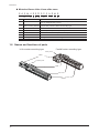
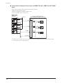
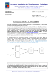
1.6 Names and functions of parts
In-line motor mounting type
Parallel motor mounting type
Pulley cover
䠩otor
Coupling case
•
Table
Top cover
Sensor䚷rail
−4−
Introduction
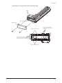
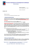
Mechanism of the parallel motor mounting type
Pulley
㻮㼑㼘㼠
㻼㼡㼘㼘㼑㼥㻌cover
•
㼀㼑㼚㼟㼕㼛㼚㻌㼍㼐㼖㼡㼟㼠㼕㼚㼓㻌㼟㼜㼞㼕㼚㼓
㻹㼛㼠㼛㼞㻌㼙㼛㼡㼚㼠㼕㼚㼓㻌㼟㼏㼞㼑㼣
Springs for belt tension adjustment
are installed.
㼀㼑㼚㼟㼕㼛㼚㻌㼍㼐㼖㼡㼟㼠㼕㼚㼓㻌㼟㼏㼞㼑㼣
The motor is installed in the position
where the belt is fixed with proper tension.
㻹㼛㼠㼛㼞㻌㼙㼛㼡㼚㼠㼕㼚㼓㻌㼟㼏㼞㼑㼣
−5−
Installation
2 Installation
2.1 Location for installation
The motorized actuator has been designed and manufactured to be incorporated in general industrial equipment.
Install them in a well-ventilated location that provides easy access for inspection. The location must also satisfy the
following conditions.
•
•
•
•
•
•
•
•
•
•
•
•
Inside an enclosure that is installed indoors (provide vent holes)
Operating ambient temperature: 0 to +40 ° C (+32 to +104 ° F) (non-freezing)
Operating ambient humidity 85% or less (non-condensing)
Area that is free of explosive atmosphere or toxic gas (such as sulfuric gas) or liquid
Area not exposed to direct sun
Area free of excessive amount of dust, iron particles or the like
Area not subject to splashing water (rain, water droplets), oil (oil droplets) or other liquids
Area free of excessive salt
Area not subject to continuous vibration or excessive shocks
Area free of excessive electromagnetic noise (from welders, power machinery, etc.)
Area free of radioactive materials, magnetic fields or vacuum
1000 m (3300 ft.) or lower above sea level
2.2 Installation direction
The motorized linear slide can be installed in any direction.
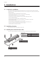
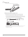
2.3 Installing the motorized linear slide
To prevent vibration and deflection of the linear slide, install it on a metal surface of sufficient strength.
Mounting plate
Iron
Aluminum
EAS4
Flatness
per 200 mm (7.87 in.) EAS6
Thickness
EAS4
EAS6
EAS4
EAS6
−6−
Tightening torque
M5 5 N䡡m (710 oz-in)
M6 5 N䡡m (710 oz-in)
6 mm (0.23 in.) or less
8 mm (0.31 in.) or less
5 mm (0.20 in.) or more
10 mm (0.39 in.) or more
0.06 mm (0.0023 in.) or less
0.07 mm (0.0027 in.) or less
Installation
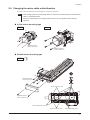
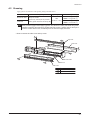
2.4 Changing the motor cable outlet direction
The motor cable outlet direction can be changed according to the equipment.
Note
•• When•changing•the•motor•cable•outlet•direction,•remove•the•load•and•keep•the•motorized•linear•
slide•in•a•horizontal•position.
•• When•the•outlet•direction•has•changed,•perform•return-to-home•operation•before•starting•
operation.
In-line motor mounting type
EAS4
EAS6
90°
90°
•
Tightening torque
1.0 N䞉m (142 oz-in)
Tightening torque
2.4 N·m (340 oz-in)
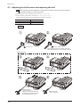
Parallel motor mounting type
EAS4
ḧ
90°
90°
Tightening torque
1.0 N䞉m (142 oz-in)
•
Motor mounting screw
Tightening torque
1.0 N䞉m (142 oz-in)
Tension adjusting screw
Motor mounting screw
Tension adjusting spring
−7−
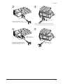
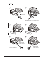
Installation
Ḩ
ḩ
3 turns or less
When loosening screws, the tension of the belt
will be adjusted properly by the strength of springs.
Tentatively mount the motor so that
the motor can be shifted slightly.
•
ḫ
Ḫ
Tightening torque
1.0 N䞉m (142 oz-in)
Tighten the screws with pressing
the motorin the direction of arrows
so that the motor does not tilt.
EAS6
ḧ
Tightening torque
1.0 N䞉m (142 oz-in)
Tightening torque
1.0 N䞉m (142 oz-in)
90°
90°
•
Tension adjusting screw
Tension adjusting spring
−8−
Installation
ḩ
Ḩ
3 turns or less
Tentatively mount the motor
so that the motor can be shifted slightly.
When loosening screws, the tension of the belt
will be adjusted properly by the strength of springs.
•
Ḫ
ḫ
Tightening torque
2.4 N䞉m (340 oz-in)
Tighten the screws with pressing
the motorin the direction of arrows
so that the motor does not tilt.
Tightening torque
2.4 N䞉m (340 oz-in)
−9−
Installation
2.5 Installing a load
Install a load with screws using the load-mounting screw hole in the table.
EAS4
EAS6
Tightening torque
M4 2.4 N䡡m (340 oz-in)
M5 5 N䡡m (710 oz-in)
•
EAS4
EAS6
8 mm (0.31 in.) or less
10 mm (0.39 in.) or less
When the electromagnetic brake type is used
When the motorized linear slide with an electromagnetic brake is used, the table cannot move unless the
electromagnetic brake is released. To release the electromagnetic brake, a DC power supply is required.
1.• Connect•the•"electromagnetic•brake•cable"•and•supplied•"cable•for•electromagnetic•brake."
2.• Connects•the•24•VDC•power•supply•to•"cable•for•electromagnetic•brake."•Connect•the•white•lead•wire•
to•the•+24•VDC•terminal,•and•the•black•lead•wire•to•the•GND•terminal.•When•turning•on•the•power,•the•
electromagnetic•brake•will•be•released•and•the•table•will•be•able•to•move•by•hand.
㻿㼣㼕㼠㼏㼔
㻱㼘㼑㼏㼠㼞㼛㼙㼍㼓㼚㼑㼠㼕㼏㻌㼎㼞㼍㼗㼑㻌㼏㼍㼎㼘㼑
㼃㼔㼕㼠㼑
㻯㼍㼎㼘㼑㻌㼒㼛㼞㻌㼑㼘㼑㼏㼠㼞㼛㼙㼍㼓㼚㼑㼠㼕㼏㻌㼎㼞㼍㼗㼑 㻮㼘㼍㼏㼗
Surge suppressor㻌∗2㻌
㻰㻯㻌㼜㼛㼣㼑㼞㻌㼟㼡㼜㼜㼘㼥
24 VDC±5% ∗1
㻹㼛㼠㼛㼞㻌㼏㼍㼎㼘㼑
•
*1 The current capacity varies depending on the motorized linear slide size and cable length. For details, refer to p.26 "6.5
Power supply current capacity."
*2 The surge suppressor comes with the product if the driver which combines the motorized linear slide with an
electromagnetic brake is the ARD-K.
−10−
Connection
3 Connection
3.1 Connecting to the driver
Refer to the Driver OPERATING MANUAL or USER MANUAL for connection method.
3.2 Grounding the motorized linear slide
Be sure to ground the Protective Earth Terminal (screw size: M4) of the linear slide.
(Not required when the power supply of the driver is 24 VDC.)
2
• Grounding wire: AWG18 (0.75 mm ) larger
• Tightening torque: 1.2 N·m (170 oz-in)
To ground the linear slide, use a round terminal and secure it with
a screw over an inner clip washer. The grounding wire and crimp
terminal do not come with the linear slide.
PE
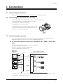
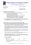
3.3 Connecting the sensors
This section explains examples for how to connect the driver and accessory sensor set. For details, refer to the
OPERATING MANUAL for the sensor set or the Driver OPERATING MANUAL.
Connection example for the sensor set PAES-S-4X/Y, PAES-S-6X/Y (NPN
type)
The connection example is shown based on the following conditions.
• Return-to-home method: 3 sensors
• Logic of +LS output, ‒LS output: Normally closed
• Logic of HOMES output: Normally open
PAES-S-4X/Y
PAES-S-6X/Y
(NPN type)
DC24 V
Brown
Pink ∗
Black
Blue
•
Built-in controller type driver
(Driver model ARD-KD,ARD-AD,ARD-CD)
+LS
Sensor I/O
4.4 kΩ
1 kΩ
Brown
Pink ∗
Black
Blue
-LS
4.4 kΩ
1 kΩ
Brown
Pink ∗
Black
Blue
HOMES
4.4 kΩ
1 kΩ
IN-COM2
0V
* Normally open or normally closed can be selected by the connection method of the sensor. When selecting normally
closed, connect the brown lead and pink lead.
−11−
Connection
Connection example for the sensor set PAES-SY-4X/Y, PAES-SY-6X/Y (PNP
type)
The connection example is shown based on the following conditions.
• Return-to-home method: 3 sensors
• Logic of +LS output, ‒LS output: Normally closed
• Logic of HOMES output: Normally open
PAES-SY-4X/Y
PAES-SY-6X/Y
(PNP type)
Built-in controller type driver
(Driver model ARD-KD,ARD-AD,ARD-CD)
DC24 V
Brown
Pink ∗
+LS
Black
Blue
Sensor I/O
4.4 kΩ
1 kΩ
Brown
Pink ∗
•
-LS
Black
Blue
4.4 kΩ
1 kΩ
Brown
Pink ∗
HOMES
Black
Blue
4.4 kΩ
1 kΩ
IN-COM2
0V
* Normally open or normally closed can be selected by the connection method of the sensor. When selecting normally
closed, connect the brown lead and pink lead.
−12−
Maintenance
4 Maintenance
This chapter explains the maintenance items in order to operate motorized actuators safely and efficiently. If an
abnormal condition is noted on the motorized actuator, discontinue any use and contact your nearest Oriental Motor
sales office.
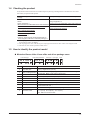
4.1 Inspection Items and Timing
Perform maintenance after each applicable period specified in the tables below. The schedule assumes that the
motorized linear slide is operated eight hours a day. Shorten the maintenance intervals accordingly if the operation
rate is high, such as when the motorized linear slide is operated continuously day and night.
Maintenance•time•period
External•check
Internal•check•
When•operated•for•the•first•time•
○
–
Six•months•after•initial•operation
○
○
Every•six•months•thereafter
○
○
External Check
Check the items specified in table below.
Item•
Motorized•
linear•slide
What•to•check
Action•if•problem•is•found•
••Are•there•any•loose•screws•which•have•mounted•the•
motorized•linear•slide?
••Are•there•any•loose•screws•which•have•mounted•the•load?
••Are•there•any•loose•screws•which•have•mounted•the•motor?
Tighten•the•screws•securely.•
Cables•
••Are•there•any•scratches•or•areas•under•stress•on•the•cable?
••Are•there•any•loose•connections•on•the•motor•or•driver?•
Disconnect•and•reconnect•the•
connector•or•replace•the•cable.•
Operation•
Are•there•any•abnormal•noise•or•vibration•from•the•bearings,•
etc.?•
Check•the•installation•of•the•load•
and•operating•speed•again.•
External Cleaning
•
•
•
•
•
Clean the exterior surface of the motorized linear slide whenever necessary.
Wipe off any dirt and stains using a soft cloth.
Do not apply compressed air. Dust may enter through gaps.
Do not use petroleum solvents, since they will damage the coated surface.
To remove stubborn stains, wipe the area using a soft cloth moistened with neutral detergent.
Internal Check
Visually check the internal condition of the motorized linear slide. Check the items specified in table below. Even if
the grease has turned brown, lubrication condition is deemed appropriate if the running surface still appears glossy.
Refer to p.15 for how to apply grease.
Item•
Ball-screw•shaft•
Guide•rail•
What•to•check
Action•if•problem•is•found
Are•there•any•deposits•of•foreign•matter•
such•as•dust?•
Remove•the•foreign•matter.•
Has•the•grease•lost•its•gloss•or•been•
consumed?•
Clean•the•screw•shaft•with•a•soft•cloth•and•
apply•grease•to•the•nut•running•groove.•
Are•there•any•deposits•of•foreign•matter•
such•as•dust?
Remove•the•foreign•matter.•
Has•the•grease•lost•its•gloss•or•been•
consumed?•
Use•a•soft•cloth•to•clean•the•ball•rolling•
grooves•on•both•sides•of•the•guide•rail,•and•
add•grease•from•the•grease•nipple.•
−13−
Maintenance
Checking the belt (when using the parallel motor mounting type)
Remove the pulley cover to check the belt condition.
Replace the belt if the following condition can be checked at the time of maintenance. See p.16 for how to replace the
belt.
Note
Remove•the•load•and•place•the•motorized•linear•slide•horizontally•before•performing•inspection•
and•maintenance•of•belt.
Inspection•interval
Inspection•item
Every•500•km•(310•mi.)•in•mileage
••Is•there•any•crack•on•the•belt•rubber?
••Is•there•any•stripped•teeth•on•the•belt?
••Is•there•any•abnormal•abrasion•on•facing•fabric•of•the•belt?
•• How•to•remove•and•install•the•pulley•cover
•
Tightening torque
1.0 N䞉m (142 oz-in)
−14−
Maintenance
4.2 Greasing
Apply grease as an indication of the greasing timing in the table below.
Greasing•timing
Type•of•grease
Ball-screw•shaft•
••Every•six•months
••Once•every•100•km•(62•mi)•of•travel
Guide•rail•
••When•grease•becomes•extremely•dirty
Note
Grease•amount
EAS4:0.3•cm3•(0.018•in3)
AFF
EAS6:0.4•cm3(0.024•in3)
(THK•CO.,•LTD.)
EAS4:0.7•cm3•(0.043•in3)
EAS6:1.5•cm3(0.092•in3)
Wear•protective•goggles•when•applying•grease.•Pay•attention•to•safety•and•handle•the•grease•
carefully•by•following•the•instructions•provided•with•that•product.•If•grease•gets•into•the•eyes•or•
comes•in•contact•with•the•skin,•immediately•flush•the•area•thoroughly•with•water.
•• How•to•remove•the•side•cover•and•top•cover
B
Top cover
B
A
Side cover
A
A
•
A
Ball-screw shaft
A
Guide rail
Side cover
Tightening torque
A
M3 0.6 N䞉m (85 oz-in)
B
M4 1.0 N䞉m (142 oz-in.)
−15−
Maintenance
4.3 Adjusting the belt tension and replacing the belt
When•performing•tension•adjustment•or•replacement•of•the•belt,•remove•the•load•and•keep•the•
motorized•linear•slide•in•a•horizontal•position.
• Perform the belt tension adjustment in the order of ①→②→⑤→⑥
• Perform the belt replacement in the order of ①→②→③→④→⑤→⑥
Use the following accessories (sold separately) for the belt replacement.
Note
Motorized•linear•slide•model
Belt•model
EAS4
LS-LVCS2M060186
EAS6
LS-LVCS3M080252
($6
ḧ
Ḩ
WXUQVRUOHVV
WXUQVRUOHVV
:KHQORRVHQLQJVFUHZVWKHWHQVLRQRIWKHEHOW
ZLOOEHDGMXVWHGSURSHUO\E\WKHVWUHQJWKRIVSULQJV
5HSODFHWKHEHOW
ḩ
Ḫ
ḫ
Ḭ
•
7LJKWHQLQJWRUTXH
1䞉PR]LQ
7LJKWHQWKHVFUHZVZLWKSUHVVLQJ
WKHPRWRULQWKHGLUHFWLRQRIDUURZV
VRWKDWWKHPRWRUGRHVQRWWLOW
−16−
7LJKWHQLQJWRUTXH
1䞉PR]LQ
Maintenance
($6
ḧ
Ḩ
WXUQVRUOHVV
WXUQVRUOHVV
:KHQORRVHQLQJVFUHZVWKHWHQVLRQRIWKHEHOW
ZLOOEHDGMXVWHGSURSHUO\E\WKHVWUHQJWKRIVSULQJV
5HSODFHWKHEHOW
ḩ
Ḫ
ḫ
Ḭ
•
7LJKWHQLQJWRUTXH
1䞉PR]LQ
7LJKWHQWKHVFUHZVZLWKSUHVVLQJ
WKHPRWRULQWKHGLUHFWLRQRIDUURZV
VRWKDWWKHPRWRUGRHVQRWWLOW
7LJKWHQLQJWRUTXH
1䞉PR]LQ
−17−
Maintenance
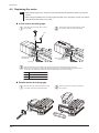
4.4 Replacing the motor
Note
•• When•replacing•the•motor,•remove•the•load•and•keep•the•motorized•linear•slide•in•a•horizontal•
position.
•• When•using•the•parallel•motor•mounting•type•linear•slide,•use•a•new•pulley.•Contact•your•nearest•
Oriental•Motor•sales•office•for•the•pulley.
In-line motor mounting type
ḧ
Open the cap and loosen the screws of
the coupling.
䐠
Remove the motor by loosening the screws
(4 locations) that are secured the motor.
Cap
•
Hexagonal socket
head screw
Motor mounting screw
(4 locations)
Coupling
䐡
When installing the motor, perform the reverse procedure to removing the motor. (䐠䊻䐟)
Refer to p.7 "Changing the cable outlet direction of the motor" for the tightening torque of the motor
mounting screw. Refer to the table below for the tightening torque of the coupling.
Tightening torque
EAS4
M1.6
EAS6
M2.5 1.0 N䞉m (142 oz-in)
0.25 N䞉m (35 oz-in)
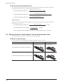
Parallel motor mounting type
ḧ
−18−
Remove the motor by loosening the screws
(4 locations) that are secured the motor.
Ḩ
When the motor is removed, the belt can
be removed.
Maintenance
ḩ
Install the pulley to the new motor.
A
Tightening torque
EAS4
18.5 mm (0.73 in)
M3 0.8 N䞉m (113 oz-in)
EAS6
20.5 mm (0.81 in)
M4 1.7 N䞉m (241 oz-in)
A
shaft flat
Fix the screw at the location other
than the shaft flat on the motor shaft.
•
Ḫ
Tentatively mount the motor so that the motor can be shifted slightly. After tentatively attaching the motor,
perform steps (䐠䊻䐢䊻䐣䊻䐤) according to p.16 "Adjusting the belt tension and replacing the belt."
−19−
Standard•General•specifications
5 Standard General specifications
5.1 Standard
Machinery Directive
The motorized actuators and drivers have been designed and manufactured to be incorporated in general industrial
equipment, and a Declaration of Incorporation of Partly Completed Machinery is issued with them according to the
Machinery Directive.
• Applicable standard: EN ISO 12100
Hazardous•substances
The products do not contain the substances exceeding the restriction values of RoHS Directive (2011/65/EU).
5.2 General specifications
Installation conditions
The product described in this manual has been designed and manufactured to be incorporated in general industrial
equipment.
EAS•Series
Power•input
DC•power•supply
Over•voltage•category
Ⅱ
Protection•against•electric•shock
Pollution•degree
AC•power•supply
ClassⅠ
2
Degree•of•protection
3
ー
Noise•level
72•dB
Environmental conditions
Operation•environment•
Ambient•
temperature•
0•to•+40•ºC•(+32•to•+104•ºF)•
(non-freezing)
Humidity•
Altitude
−20−
Storage•environment
Shipping•environment
–20•to•+60•ºC (–4•to•+140•ºF)
(non-freezing)•
85%•or•less•(non-condensing)•
Up•to•1000•m•(3300•ft.)•
above•sea•level•
Up•to•3000•m•(10000•ft.)•
above•sea•level•
Up•to•3000•m•(10000•ft.)•
above•sea•level•
Before•starting•operation
6 Before starting operation
6.1 Operation data setting for the motorized linear slide
When the minimum travel amount, travel amount, operating speed and acceleration/deceleration speed are set, the
following calculation is required.
Minimum travel amount
•
•
The minimum travel amount can be changed using the driver switch or parameters (electronic gear A, electronic gear
B).
Ball screw lead䠄mm䠅
Minimum travel amount䠄mm䠅 =
Motor resolution䠄P/R䠅
Motor resolution䠄P/R䠅 = 1000 × 䠄Electronic gear B ÷ Electronic gear A㻌䠅
Setting•example
When setting the minimum travel amount to 0.01 mm for 6 mm lead of the motorized linear slide
6 䠄mm䠅
Minimum travel amount䠄mm䠅 =
= 0.01䠄mm䠅
Motor resolution䠄P/R䠅
Motor resolution䠄P/R䠅 =
•
6 䠄mm䠅
= 600䠄P/R䠅
0.01䠄mm䠅
Motor resolution䠄P/R䠅 = 1000 × 䠄 Electronic gear B ÷ Electronic gear A 䠅㻌= 600 䠄P/R䠅
600
Electronic gear B
=
=
1000
Electronic gear A
3
5
When setting the minimum travel amount to 0.01 mm,
set the electronic gear A to 5 and the electronic gear B to 3.
Travel amount
The travel amount is set by number of pulses.
Travel amount(mm) = Number of pulses (pulse) × Minimum travel amount(mm)
* Number of pulses: For the pulse input types only. It will be the position (step) for the built-in controller types.
Setting•example
When the motorized linear slide which minimum travel amount is set to 0.01 mm is moved by 30 mm
Travel amount䠄mm䠅 = Number of pulses (pulse) × 0.01䠄mm䠅 = 30 䠄mm䠅
•
•
Number of pulses (pulse) =
30 䠄mm䠅
= 3000 pulse
0.01䠄mm䠅
When moving the motorized linear
slide by 30 mm, set 3000 pulses.
Operating speed
The operating speed is set by the pulse speed.
Operating speed (mm/s) = Pulse speed (Hz) × Minimum travel amount(mm)
* Pulse speed: For the pulse input types only. It will be the operating speed (Hz) for the built-in controller types.
Setting•example
When the motorized linear slide which minimum travel amount is set to 0.01 mm is moved at the operating speed of
50 mm/s
Operating speed (mm/s) = Pulse speed (Hz) × 0.01䠄mm䠅 = 50䠄mm/s䠅
•
•
Pulse speed (Hz) =
50 䠄mm/s䠅
= 5000 Hz
0.01䠄mm䠅
When moving the motorized linear slide at the operating
speed of 50 mm/sec, set 5000 Hz.
−21−
Before•starting•operation
Acceleration/deceleration speed
The acceleration/deceleration speed is set by any of the acceleration/deceleration rate (ms/kHz), acceleration/
deceleration rate [ms/(1000 r/min)] or acceleration/deceleration time (sec).
Minimum travel amount䠄mm䠅㻌×㻌1000
Acceleration/deceleration speed䠄m/s2䠅 =
Acceleration/deceleration rate䠄ms/kHz䠅
•
•
•
•
Acceleration/deceleration speed䠄m/s2䠅 =
•
•
Acceleration/deceleration speed䠄m/s2䠅 =
Ball screw lead䠄mm䠅㻌×㻌1000
60㻌×㻌Acceleration/deceleration rate㼇ms/䠄1000 r/min䠅㼉
Operating speed䠄mm/s䠅㻌
Acceleration/deceleration time䠄sec䠅
Setting•example
When the motorized linear slide which minimum travel amount is set to 0.01 mm is moved at the acceleration/
deceleration speed of 10 m/s2
0.01䠄mm䠅 × 1000
Acceleration/deceleration speed䠄m/s2䠅 =
= 10䠄m/s2䠅
Acceleration/deceleration rate䠄ms/kHz䠅
•
•
Acceleration/deceleration rate䠄ms/kHz䠅 =
0.01䠄mm䠅× 1000
10 䠄m/s2䠅
= 1 ms/kHz
When moving the motorized linear slide at the acceleration/deceleration speed of 10 m/s2, set 1 ms/kHz.
6.2 Moving direction of the table for the motorized linear slide
The moving direction of the table is set as follows at the time of shipment.
Built-in controller type
The moving direction varies depending on the setting of plus/minus of the travel amount.
In-line•motor•mounting•type Parallel•motor•mounting•type
The table moves to
opposite the motor side
The table moves to
the motor side
The table moves to
the motor side
The table moves to
opposite the motor side
When•setting•the•travel•amount•to•the•plus•side
When•setting•the•travel•amount•to•the•minus•side
−22−
Before•starting•operation
Pulse input type
The moving direction varies depending on the input method of the pulse signal.
In-line•motor•mounting•type Parallel•motor•mounting•type
••2-pulse•input•mode
When•inputting•the•pulse•signal•to•the•CW•input
The table moves to
opposite the motor side
The table moves to
the motor side
The table moves to
the motor side
The table moves to
opposite the motor side
••1-pulse•input•mode
When•inputting•the•pulse•signal•to•the•PLS•input•
while•the•DIR•input•is•OFF
••2-pulse•input•mode
When•inputting•the•pulse•signal•to•the•CCW•input
••1-pulse•input•mode
When•inputting•the•pulse•signal•to•the•PLS•input•
while•the•DIR•input•is•ON
6.3 Data setter, data setting software
The minimum travel amount or operation data can be set using the accessory data setter OPX-2A (sold separately) or
data setting software MEXE02. Provide as necessary.
Notes about using the data setter OPX-2A
In addition to setting operation data or parameters, the OPX-2A can save data that is set in the driver.
Data can be saved (uploaded) by a driver basis. The saved data can be written to drivers which model names are the
same. Refer to the operating manual of the OPX-2A for details.
Notes about using the data setting software MEXE02
• When creating or editing data using the MEXE02, set data by selecting the series name of the equipped motor and
driver model name.
• For the EAS Series, there are two types of driver to combine the actuator: One is the LSD drivers (driver model:
LSD-) and the other is the ARD drivers (driver model: ARD-). When operation data and parameters are set
using the MEXE02, select the following series in the product selection screen. If you have any questions, contact
your nearest Oriental Motor sales office.
Driver
LSD•driver
ARD•driver
MEXE02•version
Series•to•be•selected
2.6
DGⅡ /•EAS
3.00•or•later
AR
2.6
AR
3.00•or•later
AR
• Data can be saved by a driver basis. The saved data can be written to drivers which model names are the same.
−23−
Before•starting•operation
6.4 Parameter setting list
For ARD-K, ARD-A, ARD-C and ARD-S
An example to set the minimum travel amount to 0.01 mm (0.0004 in.) is shown below.
represents parameters to be changed.
Note
•• Set•the•starting•speed•to•6•mm/s•(0.24•in/s)•or•less.
•• Set•the•operating•speed•by•checking•the•specification•of•the•maximum•speed•for•each•linear•slide.•
•• Set•the•operating•speed•of•JOG•operation•for•test•operation•to•250•mm/s•(9.84•in/s)•or•less.
•• Lead:•6•mm•(0.24•in.)
Setting•example•
Setting•items•
Ball•screw•lead•[mm•(in.)]
Resolution•{•Minimum•travel•amount•[mm•(in.)]•}
Electronic• Electronic•gear•A1
gear•
Electronic•gear•B
Operation•
Motor•rotation•direction
setting
Operating•speed•of•return•operation•[r/min]
Return•to•
electrical• Acceleration•and•deceleration•rate•of•return•
operation•[ms/(1000•r/min)]
home•
operation
Starting•speed•of•return•operation•[r/min]
Operating•speed•of•JOG•operation•[r/min]
Test•
operation
*1
*2
Setting•value
6•(0.24)
600•[0.01•(0.0004)]
5
3
Positive•direction=CW•
(The•linear•slide•table•moves•to•
opposite•the•motor•side)•*2
1000
50
60
1000
Initial•value•*1
Converted•
value
−
−
Setting•value
6•(0.24)
1000•[0.006•(0.0002)]
10
10
Positive•direction=CW•
(The•linear•slide•table•moves•to•
opposite•the•motor•side)•*2
−
−
−
100•[mm/s]
3.94•[in/s]
2•[m/s2]
2
6.6•[ft/s ]
6•[mm/s]
0.24•[in/s]
100•[mm/s]
3.94•[in/s]
30
100
30
30
2
Acceleration•and•deceleration•rate•of•JOG•
operation•[ms/(1000•r/min)]
50
Starting•speed•of•JOG•operation•[r/min]
60
2•[m/s ]
6.6•[ft/s2]
6•[mm/s]
0.24•[in/s]
100
30
Converted•
value
−
−
−
−
−
3•[mm/s]
0.12•[in/s]
1•[m/s2]
3.3•[ft/s2]
3•[mm/s]
0.12•[in/s]
3•[mm/s]
0.12•[in/s]
1•[m/s2]
3.3•[ft/s2]
3•[mm/s]
0.12•[in/s]
Factory setting data or initialized data.
This is the table moving direction of the in-line motor mounting type. For the parallel motor mounting type, the table moves in the opposite direction of the in-line
motor mounting type.
•• Lead:12•mm•(0.47•in.)
Setting•example
Setting•items•
Ball•screw•lead•[mm•(in.)]
Resolution•{•Minimum•travel•amount•[mm•(in.)]•}
Electronic• Electronic•gear•A1
Electronic•gear•B
gear•
Operation•
Motor•rotation•direction
setting•
Operating•speed•of•return•operation•[r/min]
Return•to•
electrical• Acceleration•and•deceleration•rate•of•return•
home•
operation•[ms/(1000•r/min)]
operation•
Test•
operation
*1
*2
Setting•value
12•(0.47)
1200•[0.01•(0.0004)]•
5
6
Positive•direction=CW•
(The•linear•slide•table•moves•to•
opposite•the•motor•side)•*2
500
100
Starting•speed•of•return•operation•[r/min]
30
Operating•speed•of•JOG•operation•[r/min]
500
Initial•value•*1
Converted•
value
−
−
−
−
−
100•[mm/s]
3.94•[in/s]
2•[m/s2]
6.6•[ft/s2]
6•[mm/s]
0.24•[in/s]
100•[mm/s]
3.94•[in/s]
Setting•value
12•(0.47)
1000•[0.012•(0.0005)]
10
10
Positive•direction=CW•
(The•linear•slide•table•moves•to•
opposite•the•motor•side)•*2
30
100
30
30
2
Acceleration•and•deceleration•rate•of•JOG•
operation•[ms/(1000•r/min)]
100
Starting•speed•of•JOG•operation•[r/min]
30
2•[m/s ]
6.6•[ft/s2]
6•[mm/s]
0.24•[in/s]
100
30
Converted•
value
−
−
−
−
−
6•[mm/s]
0.24•[in/s]
2•[m/s2]
6.6•[ft/s2]
6•[mm/s]
0.24•[in/s]
6•[mm/s]
0.24•[in/s]
2•[m/s2]
6.6•[ft/s2]
6•[mm/s]
0.24•[in/s]
Factory setting data or initialized data.
This is the table moving direction of the in-line motor mounting type. For the parallel motor mounting type, the table moves in the opposite direction of the in-line
motor mounting type.
−24−
Before•starting•operation
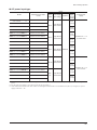
For ARD-KD, ARD-AD and ARD-CD
An example to set the minimum travel amount to 0.01 (0.0004 in.) mm is shown below.
represents parameters to be changed.
Note
•• Set•the•starting•speed•to•6•mm/s•(0.24•in/s)•or•less.
•• Set•the•operating•speed•by•checking•the•specification•of•the•maximum•speed•for•each•linear•slide.
•• Set•the•operating•speed•of•JOG•operation•for•test•operation•to•250•mm/s•(9.84•in/s)•or•less.
•• When•performing•sensorless•return-to-home•operation•upward•in•a•vertical•direction•with•the•EAS4•type,•
keep•the•load•mass•to•be•less•than•4•kg•(8.8•lb).•If•the•load•mass•is•4•kg•(8.8•lb)•or•more,•the•linear•slide•
cannot•push•up•to•the•position•of•the•actuator•end,•causing•variation•in•the•stopping•accuracy•of•return-tohome.•
•• For•the•travel•amount•of•the•"position•offset•of•home-seeking,"•set•the•following•value•or•larger.••
If•sensorless•return-to-home•operation•is•performed•keeping•the•initial•values,•the•linear•slide•table•
becomes•a•state•of•contacting•the•dedicated•stop•buffer,•causing•a•negative•effect•on•the•stopping•
accuracy•of•return-to-home.•
・EAS4:•3•mm•(0.12•in.)•or•more•(setting•value:•100,•the•table•moves•300•steps•from•the•actuator•end)••
・EAS6:•6•mm•(0.24•in.)•or•more•(setting•value:•400,•the•table•moves•600•steps•from•the•actuator•end)
•• Lead:6•mm•(0.24•in.)
Setting•example
Setting•items•
Setting•value
Ball•screw•lead•[mm•(in.)]
Resolution•{•(Minimum•travel•amount•[mm•(in.)]•}
Electronic•gear•A
Electronic•gear•B
Positive•direction=CW•
(The•linear•slide•table•moves•
to•opposite•the•motor•side)•*3
Coordination
Motor•rotation•direction
Operation•
data•
Position•[step]
1000
Operating•speed•[Hz]
10000
Acceleration•(deceleration)•rate•
[ms/kHz]•*2
JOG•operating•speed•[Hz]
Operation•
JOG•acceleration•(deceleration)•
rate•[ms/kHz]•*2
JOG•starting•speed•[Hz]
Position•offset•of•
home-seeking•[step]
1
10000
1
600
Home-seeking•mode
Starting•speed•of•home-seeking•
[Hz]
Return-to-•
home•
6•(0.24)
600•[0.01•(0.0004)]
5
3
Push•mode
2500
EAS4
100
EAS6
400
Starting•direction•of•home-seeking•
Negative•direction••
(Return-to-home••operation•
starts•to•the•motor•side)•*3
Positive•software•limit•[step]
(Stroke× 100)+300
Negative•software•limit•[step]
− 200
Coordination
*1
*2
*3
Initial•value•*1
Converted•value
Setting•value
Converted•value
−
−
6•(0.24)
1000•[0.006•(0.0002)]
1
1
−
−
−
10•[mm]
0.39•[in.]
100•[mm/s]
3.94•[in/s]
10•[m/s2]
32.8•[ft/s2]
100•[mm/s]
3.94•[in/s]
10•[m/s2]
32.8•[ft/s2]
6•[mm/s]
0.24•[in/s]
−
25•[mm/s]
0.98•[in/s]
1•[mm]
0.04•[in.]
4•[mm]
0.16•[in.]
−
Stroke+3•[mm]
Stroke+0.12•[in.]
− 2•[mm]
− 0.08•[in.]
Positive•direction=CW•
(The•linear•slide•table•moves•to•
opposite•the•motor•side)•*3
0
1000
1
1000
1
500
3-sensor•mode•
500
0
0
Positive•direction(Returnto-home•operation•starts•to•
opposite•the•motor•side)•*3
8388607
− 8388608
−
0•[mm]
0•[in.]
6•[mm/s]
0.24•[in/s]
6•[m/s2]
19.7•[ft/s2]
6•[mm/s]
0.24•[in/s]
6•[m/s2]
19.7•[ft/s2]
3•[mm/s]
0.12•[in/s]
−
3•[mm/s]
0.12•[in/s]
0•[mm]
0•[in.]
0•[mm]
0•[in.]
−
50331.642•[mm]
1981.56•[in.]
− 50331.648•[mm]
− 1981.56•[in.]
Factory setting data or initialized data.
When setting the acceleration/deceleration rate via network, input integral number. Set by increasing the value calculated by the conversion formula to 1000 times.
This is the table moving direction of the in-line motor mounting type. For the parallel motor mounting type, the table moves in the opposite direction of the in-line
motor mounting type.
−25−
Before•starting•operation
•• Lead:12•mm•(0.47•in.)
Setting•example
Setting•value
Converted•value•
Setting•items•
Ball•screw•lead•[mm•(in.)]
12•(0.47)
Resolution•{•(Minimum•travel•amount•[mm•(in.)])•}
1200•[0.01•(0.0004)]
Electronic•gear•A
5
Electronic•gear•B
6
Coordination
Positive•direction=CW•
Motor•rotation•direction
(The•linear•slide•table•moves•
to•opposite•the•motor•side)•*3
Operation•
data
Position•[step]
1000
Operating•speed•[Hz]
10000
Acceleration•(deceleration)•rate•
[ms/kHz]•*2
JOG•operating•speed•[Hz]
Operation
Return-to-•
home
1
600
Home-seeking•mode
Starting•speed•of•homeseeking[Hz]
Push•mode•
Position•offset•of•
home-seeking•
[step]
2500
EAS4
100
EAS6
400
Starting•direction•of•home-seeking•
Negative•direction•
(Return-to-home••operation•
starts•to•the•motor•side)•*3
Positive•software•limit•[step]
(Stroke× 100)+300
Negative•software•limit•[step]
− 200
Coordination
*1
*2
*3
12•(0.47)
−
−
−
−
1000•[0.012•(0.0005)]
1
1
Positive•direction=CW•
(The•linear•slide•table•moves•
to•opposite•the•motor•side)•*3
−
−
−
10•[mm]
0.39•[in.]
100•[mm/s]
3.94•[in/s]
10•[m/s2]
32.8•[ft/s2]
100•[mm/s]
3.94•[in/s]
10•[m/s2]
32.8•[ft/s2]
6•[mm/s]
0.24•[in/s]
−
25•[mm/s]
0.98•[in/s]
1•[mm]
0.04•[in.]
4•[mm]
0.16•[in.]
1
JOG•starting•speed•[Hz]
−
−
10000
JOG•acceleration•(deceleration)•
rate•[ms/kHz]•*2
Initial•value•*1
Setting•value
Converted•value•
−
0•[mm]
0•[in.]
12•[mm/s]
0.47•[in/s]
12•[m/s2]
39.4•[ft/s2]
12•[mm/s]
0.47•[in/s]
12•[m/s2]
39.4•[ft/s2]
6•[mm/s]
0.24•[in/s]
−
6•[mm/s]
0.24•[in/s]
0•[mm]
0•[in.]
0•[mm]
0•[in.]
0
1000
1
1000
1
500
3-sensor•mode
500
0
0
Positive•direction•
(Return-to-home•operation•
starts•to•opposite•the•motor•
side)•*3
−
Stroke+3•[mm]
Stroke+0.12•[in.]
− 2•[mm]
− 0.08•[in.]
8388607
− 8388608
−
100663.284•[mm]
3963.12•[in.]
− 100663.296•[mm]
− 3963.12•[in.]
Factory setting data or initialized data.
When setting the acceleration/deceleration rate via network, input integral number. Set by increasing the value calculated by the conversion formula to 1000 times.
This is the table moving direction of the in-line motor mounting type. For the parallel motor mounting type, the table moves in the opposite direction of the in-line
motor mounting type.
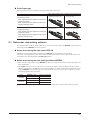
6.5 Power supply current capacity
DC power input type
Model
Motorized•Linear•slide•
model
EAS4--ARAK-
EASM4ARAK
EAS4--ARMK-
EASM4ARMK
EAS6--ARAK-
EASM6ARAK
EAS6--ARMK-
EASM6ARMK
EAS4--ARAKD-
EASM4ARAK
EAS4--ARMKD-
EASM4ARMK
EAS6--ARAKD-
EASM6ARAK
EAS6--ARMKD-
EASM6ARMK
Driver
Driver•
model
ARD-K
ARD-KD
Power•supply•
input•voltage
24•VDC± 10%•
48•VDC± 5%
24•VDC± 5%•
48•VDC± 5%
Power•supply•
current•
capacity
1.4•A••
or•more
3.1•A•
or•more
Power•supply•
for•releasing•an•
electromagnetic•
brake
—
24•VDC± 5%•*
0.1•A•or•more
—
24•VDC± 5%•*
0.3•A•or•more
1.8•A•
or•more
—
3.8•A•
or•more
—
—
—
* If the distance between the motorized linear slide and driver is extended to 20 m (65.6 ft.) or longer, use a power supply of 24 VDC± 4%.
−26−
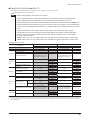
Before•starting•operation
AC power input type
Driver
Model
Motorized•Linear•slide•
model
EAS4--ARAA-
EASM4ARAC
EAS4--ARMA-
EASM4ARMC
EAS6--ARAA-
EASM6ARAC
EAS6--ARMA-
EASM6ARMC
EAS4--ARAC-
EASM4ARAC
EAS4--ARMC-
EASM4ARMC
EAS6--ARAC-
EASM6ARAC
EAS6--ARMC-
EASM6ARMC
EAS4--ARAS-
EASM4ARAC
EAS4--ARMS-
EASM4ARMC
EAS6--ARAS-
EASM6ARAC
EAS6--ARMS-
EASM6ARMC
EAS4--ARAAD-
EASM4ARAC
EAS4--ARMAD-
EASM4ARMC
EAS6--ARAAD-
EASM6ARAC
EAS6--ARMAD-
EASM6ARMC
EAS4--ARACD-
EASM4ARAC
EAS4--ARMCD-
EASM4ARMC
EAS6--ARACD-
EASM6ARAC
EAS6--ARMCD-
EASM6ARMC
Power•
supply•
Driver• Power•supply•
Frequency
current•
model input•voltage
capacity
ARD-A
ARD-C
ARD-S
ARD-AD
ARDCD
Single-Phase•
100-115•VAC
Single-Phase•
200-230•VAC
Three-Phase•
50/60•Hz
200-230•VAC
Single-Phase•
100-120•VAC
Single-Phase•
200-240•VAC
Control•power•
supply
2.9•A••
or•more
4.4•A•
or•more
1.9•A••
or•more
2.7•A•
or•more
24•VDC± 5%••*1 *3
0.75•A•or•more
1.0•A•
or•more
1.4•A•
or•more
2.4•A•
or•more
3.6•A•
or•more
1.5•A•
or•more
24•VDC± 5%••*2 *3
0.5•A•or•more
2.3•A•
or•more
*1 If a motorized linear slide with an electromagnetic brake is used, be sure to connect a 24 VDC power supply as the electromagnetic brake
power.
*2 The 24 VDC power supply is for control circuit. Be sure to connect it.
*3 If the distance between the linear slide with an electromagnetic brake and driver is extended to 20 m (65.6 ft.) or longer, use a power
supply of 24 VDC± 4%.
−27−
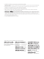
• Unauthorized reproduction or copying of all or part of this manual is prohibited.
If a new copy is required to replace an original manual that has been damaged or lost, please contact your nearest Oriental Motor
branch or sales office.
• Oriental Motor shall not be liable whatsoever for any problems relating to industrial property rights arising from use of any
information, circuit, equipment or device provided or referenced in this manual.
• Characteristics, specifications and dimensions are subject to change without notice.
• While we make every effort to offer accurate information in the manual, we welcome your input. Should you find unclear
descriptions, errors or omissions, please contact the nearest office.
and
are registered trademark or trademark of Oriental Motor Co., Ltd., in Japan and other countries.
•
• Other product names and company names mentioned in this manual may be registered trademarks or trademarks of their respective
companies and are hereby acknowledged. The third-party products mentioned in this manual are recommended products, and
references to their names shall not be construed as any form of performance guarantee. Oriental Motor is not liable whatsoever for
the performance of these third-party products.
© Copyright ORIENTAL•MOTOR•CO.,•LTD.•2013
• Please contact your nearest Oriental Motor office for further information.
Technical Support Tel:(800)468-3982
8:30 A.M. to 5:00 P.M., P.S.T. (M-F)
7:30 A.M. to 5:00 P.M., C.S.T. (M-F)
E-mail: [email protected]
www.orientalmotor.com
Headquarters and Düsseldorf Office
Tel:0211-52067-00
Fax:0211-52067-099
Munich Office
Tel:089-3181225-00 Fax:089-3181225-25
Hamburg Office
Tel:040-76910443
Fax:040-76910445
Tel:400-820-6516
Fax:021-6278-0269
Tel:(02)8228-0707
Fax:(02)8228-0708
Tel:+65-6745-7344
Fax:+65-6745-9405
Tel:01256-347090
Fax:01256-347099
Tel:(03)22875778
Fax:(03)22875528
Tel:01 47 86 97 50
Fax:01 47 82 45 16
Tel:+66-2-251-1871
Fax:+66-2-251-1872
Tel:02-93906346
Fax:02-93906348
KOREA
Tel:080-777-2042
Fax:02-2026-5495
Headquarters Tokyo, Japan
Tel:03-6744-0361
Fax:03-5826-2576