1
Thermal Control Board User Manual
·1·
1 Outline ...................................................................................................................................................... 2
2 HOW TO USE .......................................................................................................................................... 2
2.1 Printing test .................................................................................................................................... 2
2.2 On board LED................................................................................................................................ 2
3 MECHANISM .......................................................................................................................................... 2
4 CONNECTOR .......................................................................................................................................... 3
5 ESC/POS PRINTING COMMAND SET................................................................................................. 3
5.1 Set of Command............................................................................................................................. 3
5.2 Command detail ............................................................................................................................. 5
5.2.1 Print Commands.................................................................................................................. 5
5.2.2 Line spacing setting command............................................................................................ 5
5.2.3 Character command ............................................................................................................ 6
5.2.4 Bit Image Command ........................................................................................................... 8
5.2.5 Key control command ....................................................................................................... 10
5.2.6 Init command .................................................................................................................... 10
5.2.7 Status Command ............................................................................................................... 10
5.2.8 Bar Code Command.......................................................................................................... 11
APPENDIXA:CODE PAGE ................................................................................................................... 14
APPENDIXB:International characters.................................................................................................... 15
·2·
Thermal Control Board User Manual
1 Outline
Printing Method:
Paper Width:
Paper Diameter:
Resolution:
Printing Speed:
Barcode Supported:
Font:
Graphic printing:
Paper Sensor:
Head tempeture detection:
Communication Interface:
Power supply:
Head Life:
Printing width:
Operation condition:
Storage condition:
Thermal
57.5mm
55mm
203DPI
Up to 90mm/s
I25,UPC-A,UPC-E,EAN-8, EAN-13,Codebar,Code39,
Code93,Code128,Code11,MSI
ASCII(12x24)
Direct bitmap printing
Photo-sensor
Thermistor
RS232 or RS232 with TTL level
5V-9V
50km
48mm
5~45℃,20~90%RH(40℃)
-40~60℃,20~93%RH(40℃)
2 HOW TO USE
2.1 Printing test
After power up, connect JP4 and disconnect, one test page will be printed.
2.2 On board LED
There is one LED on board to indicate the status of the board. The indicator is as follows:
Blink one:
Work well
Blink two:
No printer is detected
Blink three:
No paper is detected
Blank five:
Printer mechanism is overheat.
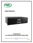
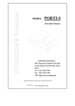
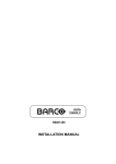
3 MECHANISM
·3·
Thermal Control Board User Manual
Printer mechanism socket
30mm
3.0mm
2.54m
5
4
RS232
3
2
TTL
1
5
4
3
2
1
40mm
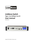
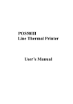
4 CONNECTOR
You can choose use RS232 or RS232 with TTL level before leaving factory. RS232 with TTL level can
get less cost.
The definition is as following:
1.
VH, the power supply for the board
2.
CTS, Paper detector(Default) or CTR flow control(GS a command set)
3.
TXD, the transmit pin for UART
4.
RXD, the receive pin for UART
5.
GND
5 ESC/POS PRINTING COMMAND SET
5.1 Set of Command
Type
Print Command
Line spacing
Command
Character
Command
Command
LF
ESC J
ESC 2
ESC 3 n
ESC a n
ESC B n
ESC ! n
ESC SO
ESC DC4
ESC { n
GS B n
ESC % n
ESC &
ESC ?
ESC R n
ESC t n
Name
Print and line feed
Print and Feed n dots paper
Select default line spacing
Set line spacing
Select justification
Set the left blank char number
Select print mode(s)
Turn double width on
Turn double width off
Turn upside-down printing mode on/off
Turn inverting printing mode on/off
Select/Cancel user-defined characters
Define user-defined characters
Cancle user-defined characters
Select and internation character set
Select character code table
·4·
Thermal Control Board User Manual
Bit Image Command
Cash drawer
command
Key Control
Command
Init Command
Status Command
ESC *
GS *
GS /
Select bit-image mode
Define downloaded bit image
Print downloaded bit image
ESC p
Generate cash drawer control pulse
ESC c 5
Enable/disable panel buttons
ESC @
ESC v n
ESC u n
GS a n
Initialize printer
Transmit paper sensor status
Transmit peripheral device status
Enable/Disable AutomaticStatus Back(ASB)
Select printing position of human readable
characters
Set bar code height
Set bar code width
Print bar code
GS H
Bar Code Command
GS h
GS w
GS k
·5·
Thermal Control Board User Manual
5.2 Command detail
TCB thermal printer control board use ESC/POS command set.
The printing command is descripted as followed format:
CMD
Format
Description
Example
Function
ASCII List by ASCII characters
Decimal List by decimal characters
Hexadecimal List by hexadecimal characters
Command function description
Command use example
5.2.1 Print Commands
LF
Format
Description
ESC J n
Format
Description
Print and line feed
ASCII
LF
Decimal 10
Hexadecimal 0A
LF prints the data in the print buffer and feeds one line.
When the print buffer is empty, LF feeds one line.
Print and feed paper
ASCII ESC J n
Decimal 27 74 n
Hexadecimal 1B 4A n
n = 0-255。
ESC J prints the data in the print buffer and feeds n dots.
The command will not change the setting set by command ESC 2,ESC 3.
5.2.2 Line spacing setting command
ESC 2
Format
Description
ESC 3 n
Format
Description
Select default line spacing
ASCII ESC 2
Decimal 27 50
Hexadecimal 1B 32
ESC 2 sets the line space to default value (30dots)
Set line spacing
ASCII ESC 3 n
Decimal 27 51 n
Hexadecimal 1B 33 n
n = 0-255
ESC 3 n sets the line spacing to n dots.
The default value is 30
·6·
Thermal Control Board User Manual
ESC a n
Format
Description
ESC B n
Format
Description
Select align mode
ASCII
ESC a n
Decimal 27 97 n
Hexadecimal 1B 61 n
Default is 0
0 ≤ m ≤ 2 or 48 ≤ m ≤ 50
Align left:
n=0,48
Aligh middle: n=1,49
Align right: n=2,50
Set left blank char nums
ASCII
ESC B n
Decimal 27 66 n
Hexadecimal 1B 42 n
Default is 0
0 ≤ m ≤ 47
5.2.3 Character command
ESC ! n
Format
Select print mode
ASCII
Decimal
Hexadecimal
ESC ! n
27 33 n
1B 21 n
Description
The default value is 0. This command is effective for all characters.
BIT0:
BIT1:
BIT2:
BIT3: 1:Emphasized mode selected
0:Emphasized mode not selected
BIT4: 1:Double Height mode selected
0:Double Height mode not selected
BIT5: 1:Double Width mode selected
0:Double Width mode not selected
BIT6: 1:Deleteline mode selected
0:Deleteline mode not selected
BIT7: 1:Underline mode selected
0:Underline mode not selected
ESC SO
Format
Select Double Width mode
ASCII
Decimal
Hexadecimal
ESC SO
27 14
1B 0E
·7·
Thermal Control Board User Manual
Description
ESC DC4
Format
Description
ESC { n
Format
Description
GS B n
Format
Description
ESC % n
Format
Description
Select Double Width mode
To turn double width off, use LF or DC4 command.
Disable Double Width mode
ASCII ESC DC4
Decimal 27 20
Hexadecimal 1B 14
Disable Double Width mode
Set/Cancel Character Updown mode
ASCII ESC { n
Decimal 27 123 n
Hexadecimal 1B 7B n
n=1:Enable Updown mode
n=0:Disable Updown Mode
Default value is 0
Turn white/black reverse printing mode on/off
ASCII ESC B n
Decimal 29 66 n
Hexadecimal 1D 42 n
n=1:Enable white/black reverse mode
n=0:Disable white/black reverse mode
Default value is 0
Enable/Disable User-defined Characters
ASCII ESC % n
Decimal 27 37 n
Hexadecimal 1B 25 n
n=1:Enable User-defined character
n=0:Disable User-defined character
ESC & s n m w
Define User-defined characters
Format
ASCII ESC & s n m w d1 d2 … dx
Decimal 27 38 s n w m d1 d2 … dx
Hexadecimal 1B 26 s n w m d1 d2 … dx
Description
The command is used to define user-defined character.Max 64 user chars can be
defined.
s= 3,32≤ n ≤ m < 127
s: Character height bytes, =3(24dots)
w: Character width 0~12(s=3)
·8·
Thermal Control Board User Manual
n: User-defined character starting code
m: User-defined characters ending code
dx:data,x=s*w
s=3
dx format:
d1 d4 d7
d2 d5 d8
d3 d6 d9
d36
dx
位7
位6
位5
位4
位3
位2
位1
位0
ESC ? n
Format
Disable user-defined character
ESC R n
Format
Select an internal character set
ASCII ESC ? n
Decimal 27 37 n
Hexadecimal 1B 25 n
Description
ESC ? n disable user-defined characters, printer will use the interal character.
ASCII ESC R n
Decimal 27 82 n
Hexadecimal 1B 52 n
Description
Select an internal character
0:USA
5:Sweden
1:France
6:Italy
2:Germany
7:Spain1
3:U.K.
8:Japan
4:Denmark 1
9:Norway
set n as follows:
10:Denmark II
11:Spain II
12:Latin America
13:Korea
ESC t n
Format
Select character code table
ASCII ESC t n
Decimal 27 116 n
Hexadecimal 1B 74 n
Description
Select a page n from the character code table as follows::
0:437
1:850
5.2.4 Bit Image Command
ESC * m nL nH d1 d2…dk
Select bit-image mode
Format
ASCII ESC * m nL nH d1 d2 … dk
Decimal 27 42 m nL nH d1 d2 … dk
Hexadecimal 1B 2A m nL nH d1 d2 … dk
Description
Attention: The command may clear the user defined char.
·9·
Thermal Control Board User Manual
This command selects a bit image mode using m for the number of dots specifed by
(nL+nH*256)
m =0,1,32,33。
nL=0-255
nH=0-3
dx=0-255
k = nL+256*nH (m=0,1)
k = (nL+256*nH)*3 (m=32,33)
The modes selected by m are as follows:
0:8dots single density,102dpi
1: 8dots double density,203dpi
31:24 dots single density,102dpi
32:24 dots double density,203dpi
The bit image format is the same as user-defined character.
GS / n
Format
Print downloaded bit image
ASCII
Decimal
Hexadecimal
GS / n
29 47 n
1D 2F n
Description
This command prints a downloaded bit image using the mode specified by n as
specified in the chart.In standard mode, this command is effective only when there is
data in the print buffer. This command is ignored if a downloaded bit image has not been
defined.
n=0-3、48-51: Specify bit image mode
n
Pattern Mode Vertical DPI Horizontal DPI
GS * x y d1…dk
Format
Description
0,48
Normal
203DPI
203DPI
1,49
Double width
203DPI
101DPI
2,50
Double height
101DPI
203DPI
3,51
Quadruple
101DPI
101DPI
Define downloaded bit image
ASCII GS * x y d1 … dk
Decimal 29 42 x y d1 … dk
Hexadecimal 1D 2A x y d1 … dk
This command defineds a downloaded bit image by using x*8 dots in the
horizontal direction and y*8 dots in the vertical direction. Once a
downloaded bit image has been define, it is avaiable until
¾ Another definition is made
¾ ESC & or ESC @ is executed
¾ The power is turned off
¾ The printer is reset
x=1~48(width),y=1~255(height),x×y < 1200, k=x×y×8
·10·
Thermal Control Board User Manual
5.2.5 Key control command
ESC c 5 n
Format
Description
Enable/Disable the panel key
ASCII ESC c 5 n
Decimal 27 99 53 n
Hexadecimal 1B 63 35 n
This command has no effection.
n=1,Disable the panel key
n=0,Enable the panel key(Default)
5.2.6 Init command
ESC @
Format
Description
Initialize the printer
ASCII ESC @
Decimal 27 64
Hexadecimal 1B 40
Initializes the printer.
¾ The print buffer is cleared.
¾ Reset the param to default value.
¾ return to standard mode
¾ Delete user-defined characters
5.2.7 Status Command
ESC v
Format
Description
GS a n
Format
Transmit paper sensor status
ASCII ESC v n
Decimal 27 118 n
Hexadecimal 1B 76 n
Transmits the status of the paper sensor as 1 byte of data.
The status byte definition:
Bit
Function
Value
0
NO PRINTER
1
2
NO PAPER
1
3
POWER ERROR
1
4
0
0
5
6
PRINTER TEMPERAUTRE OVER
1
7
Enable/Disable Automatic Status Back(ASB)
ASCII
Decimal
Hexadecimal
GS a n
29 97 n
1D 61 n
·11·
Thermal Control Board User Manual
Description
n definition as follows:
Bit
Function
0
1
2
3-4
0
5
Value
0
1
Disable/Enable ASB
Disable
Enable
Disable/Enable RTS as
flow control
Disable
Enable
6-7
When ASB is enabled, the printer will send the changed status to PC
automatically.
ESC u n
Format
Description
Transmit peripheral devices status
ASCII ESC u n
Decimal 27 117
Hexadecimal 1B 75
This command is not supported.
Return status bytes definetion:
bit0: Drawer status.
bit4: 0
Always return 0 back.
5.2.8 Bar Code Command
GS H n
Format
Description
GS h n
Format
Select printing position of human readable characters
GS H n
29 72 n
1D 48 n
ASCII
Decimal
Hexadecimal
0 ≤ n ≤3
48 ≤ n ≤51
This command selects the printing position for human readable characters
when printing a barcode. The default is n=0. Human readable characters are
printed using the font specified by GS fn. Select the printing position as
follows:
n
Printing Positioin
0,48: Not printed
1,49: Above the barcode
2,50: Below the barcode
3,51: Both above and below the barcode
Set bar code height
ASCII
Decimal
Hexadecimal
GS h
n
29 104 n
1D 68 n
·12·
Thermal Control Board User Manual
Description
GS w n
Format
Description
This command selects the height of a barcode. n specifies the number of dots
in the vertical direction. The default value is 50
1 ≤ n ≤ 255
Set bar code width
ASCII GS w
n
Decimal 29 119 n
Hexadecimal 1D 77 n
This command selects the horizontal size of a barcode.
n = 2,3
The default value is 3
GS k m d1 d2 … dk NUL
GS k m n d1 d2 … dn
ASCII
Format 1
Decimal
Hexadecimal
Format 2
ASCII
Decimal
Hexadecimal
Description
m:barcode
Format 1:
Format 2:
n:barcode
Print barcode symbology
GS k
m
d1
29 107 m
d1
1D 6B m
d1
GS k m n d1
29 107 m n d1
1D 6B m n d1
type
0 ≤ m ≤ 10
65 ≤ m ≤ 75
length
0,65
1,66
2,67
3,68
4,69
Bar code
system
UPC-A
UPC-E
EAN13
EAN8
CODE39
5,70
I25
6,71
7,72
8,73
9,74
10,75
CODEBAR
CODE93
CODE128
CODE11
MSI
m
d2
d2
d2
d2
d2
d2
Number of
characters
11,12
11,12
12,13
7,8
>1
>1
even number
>1
>1
>1
>1
>1
…
…
…
…
…
…
dk NUL
dk 0
dk 00
dn
dn
dn
Remarks
48-57
48-57
48-57
48-57
32,36,37,43,45-57,65-90
48-57
36,43,45-58,65-68
0-127
0-127
48-57
48-57
5.2.9 Control Parameter Command
ESC 7 n1 n2
Format:
Setting Control Parameter Command
ASCII:
ESC 7 n1 n2 n3
Thermal Control Board User Manual
Description:
ESC 8 n1
Format:
Description:
·13·
Decimal: 27 55 n1 n2 n3
Hexadecimal: 1B 37 n1 n2 n3
Set “max heating dots”,”heating time”, “heating interval”
n1 = 0-255 Max printing dots,Unit(8dots),Default:7(64 dots)
n2 = 3-255 Heating time,Unit(10us),Default:80(800us)
n3 = 0-255 Heating interval,Unit(10us),Default:2(20us)
The more max heting dots, the more peak current will cost
whenprinting, the faster printing speed. The max heating dots is
8*(n1+1)
The more heating time, the more density , but the slower printing
speed. If heating time is too short, blank page may occur.
The more heating interval, the more clear, but the slower
printingspeed.
Sleep parameter
ASCII: ESC 8 n1
Decimal: 27 56 n1
Hexadecimal: 1B 38 n1
Setting the time for control board to enter sleep mode.
n1 = 0-255 The time waiting for sleep after printing finished,
Unit(Second),Default:0(don’t sleep)
When control board is in sleep mode, host must send one byte(0xff)
to wake up control board. And waiting 50ms, then send printing
command and data.
NOTE:The command is useful when the system is powered by battery.
ESC 0 n1 n2 n3 d1 …
Setting Bluetooth parameter
ASCII: ESC 0 n1 n2 n3 d1 d2 … dk
Format:
Decimal: 27 48 n1 n2 n3 d1 d2 … dk
Hexadecimal: 1B 30 n1 n2 n3 d1 d2 … dk
Description: Setting blud-tooth baudrate,name,password
n1 = 0-4 baudreate,Default:0
0: 9600
1: 19200
2: 38400
3: 57600
4: 115200
n2 = the length of control board name for bluetooth
n3 = the length of control board password for bluetooth
d1…dk k=n2+n3
Note:The command is valid only when the control board is Bluetooth
type control board.
·14·
Thermal Control Board User Manual
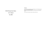
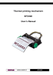
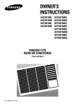
APPENDIXA:CODE PAGE
PC437
2
é
Æ
3
â
4
ä
5
à
6
å
7
ç
É
0
ü
æ
ô
ó
ú
ª
ù
º
B
í
▒
ò
Ñ
û
á
░
ö
ñ
▓
│
┤
╡
╢
C
D
└
╨
┬
╥
├
╙
─
╘
┼
╒
E
α
┴
╤
ß
Γ
π
F
≡
±
≥
≤
Σ
⌠
σ
⌡
0
Ç
É
1
ü
æ
2
é
Æ
3
â
ô
4
ä
ö
á
░
í
▒
ó
ú
ñ
5
à
ò
Ñ
D
E
└
ð
Ó
┴
Ð
ß
▓
┬
Ê
Ô
│
├
Ë
Ò
┤
─
È
õ
F
±
‗
¾
¶
8
9
A
0
Ç
8
ê
ÿ
9
ë
B
ï
C
î
¿
Ö
⌐
A
è
Ü
¬
E
Ä
F
Å
£
¼
D
ì
¥
¡
¢
½
₧
«
ƒ
»
╖
╕
╣
║
╗
╝
╜
╛
┐
╞
╓
µ
╟
╫
╚
╪
╔
┘
╩
┌
╦
█
╠
▄
═
▌
╬
▐
╧
▀
τ
Φ
÷
≈
°
Θ
·
Ω
·
δ
φ
²
ε
∩
√
∞
ⁿ
E
Ä
F
Å
×
«
ƒ
»
¥
■
PC850
8
9
A
B
C
6
å
û
7
ç
┼
I
Õ
ª
Â
ã
º
À
Ã
Í
µ
§
÷
Á
8
ê
ÿ
9
ë
Ö
A
è
Ü
B
ï
ø
C
î
£
D
ì
Ø
¿
©
®
¬
½
¼
║
╩
╗
╦
╝
╠
Î
þ
╚
Ï
Þ
╣
╔
¡
¢
┘
Ú
┌
Û
█
Ù
¸
°
¨
·
¹
ù
▄
ý
═
¦
Ý
╬
Ì
┐
¤
▀
¯
´
³
²
■
Thermal Control Board User Manual
APPENDIXB:International characters
·15·