1
FD
FD
Kinco JD 伺服系列使用手册
فهرست مطالب
9 .............................................................................................................................
9 ...................................................................................................................................
1.1-
9 .......................................................................................
1.1.1.
9 ........................................................................................................................................................
01......................................................................................................................
1.1.2.
01.............................................................................................................................................
1.1.3.
00.................................................................................................................................................................
00............................................................................................................................ FD
01.........................................................................................................................................
01..................................................................................................................... KINKO
01..........................................................................................................................................................
01............................................................................................................................................................
02...................................................................................................................
41......................................................................................... KINCO
03..................................................................................................................................................................
03....................................................................................................................................................................
04............................................................................................................................
41............................................................................................. FD
01.......................................................................................................................................................
11...............................................................................................................................................
10.................................................................................................................................................... FD
X1
11......................................................................................................................................... FD
12.....................................................................................................................................FD
X4~X6
FD
Kinco JD 伺服系列使用手册
12 .......................................................................................................................................(RS485/CAN) X4
13 ...............................................................................................................................................(RS232) X5
14 ........................................................................................................................................ (Encoder in) X6
62 ......................................................................................................................................
15 ...........................................................................................................................................................................
19 ......................................................................................................................................
14 ...................................................................................................................KINCO SERVO
20 .................................................................................................................................................................
20 ....................................................................................................................................................................
20 ................................................................................................ Kinco Servo
21 ......................................................................................................................... Kinco Server
21 ......................................................................................................................................................................
23 ..................................................................................................................................................................
23 ................................................................................................................................................. Basic Operate
29 .................................................................................................................................................. Control Loop
31 ............................................................................................................................................................ I/O
32 .............................................................................................................................. Oparation Mode
33 .................................................................................................................................................... Data Object
35 .................................................................................................................................................. Driver Config
31 ......................................................................................................... ECAN Setting (CAN open POD Setting)
33 ..........................................................................................................................................................
43 .........................................................................................................................................................
44 ................................................................................................................................................ Error History
44 ................................................................................................................................................ Control Panel
45 .................................................................................................................................................. Initialize/Save
FD
Kinco JD 伺服系列使用手册
45................................................................................................................................................ Driver Property
71...............................................................................................
41......................................................................................................................................................
41...................................................................................................................
FD
49...............................................................................................................................................
50............................................................................................................................... TRIAL OPERATION
50......................................................................................................................................................................
50...................................................................................................................................................................
51.......................................................................................................................Operating Procedure
52....................................................................................................................................... Trial Operation
53...........................................................................................................................................................
53.............................................................................................
54........................................................................... (Real _ Time Display
53...................................................................................... Control Loop
11.................................................. Pattern Operation
15....................................................................................................
F000
Group F001
Group F002
Group F003
Group F004
11................................................................................................................................... CURRENT USING MOTOR TYPE.
11............................................................................................................. PC SOFTWARE
NUMERIC DISPLAY
13.................................................................................................
Group F005
14................................................................................................................ INPUT/OUTPUT
30................................................................................................................................................................
30................................................................................................................
31......................................................................................................
32..................................................................................................
33.............................................................................................................................
MODEL
FD
Kinco JD 伺服系列使用手册
34 ........................................................................................................
34 ....................................................................................................................
39 ..............................................................................Example 7-4: Disabling Position Positive/Negative Limit Settings
91 ...................................................................................................... Example 7-5: Operation Mode Control on Drivers
90 ....................................................................................................................... (DI)
92 .....................................................................................................................................................(DO)
92 .......................................................................................................................
92 ............................................................................................................................
93 ........................................................................................................... ( DO )
93 ...................................................................................................................
91 ..............................................................................................................................
99 ............................................................................................................. OPERATION MODE
99 .................................................................................................................................. MODE -4 PULSE CONTROL
99 ..................................................................................................................................... Pulse Control
011 .........................................................................................................................................
001 ............................................................................................................................... SPEED MODE
001 ................................................................................................................................ Analog-Speed
000 ................................................................................................................................. Analog-Speed
002 ...........................................................................................................................................
004 ..................................................................................................................... Analog-Speed
004 ........................................................................................................................Analog-Speed
014 ..................................................................................................................................TORQUE MODE
014 ...................................................................................................................................
014 .................................................................................................................................
011 ...........................................................................................................................................
FD
Kinco JD 伺服系列使用手册
013.................................................................................................................Analog-Torque
019...........................................................................................................................Analog-Torque
024................................................................................................................................ 1
031........................................................................................................................................
032................................................................................. INTERNAL TORQUE CONTROL MODE
032.................................................................................................................. „6‟ MODE
HOMING MODE
421........................................................................................................................................
051...............................................................................
AUTO REVERSE
050..........................................................................................................................................
051........................................................................................................................................................
051.........................................................................................................
010............................................................................
OSCILLATION INHIBITION
011................................................................................................................................................
011........................................................................................................................................................
013...........................................................................................................................................
414......................................................................................................................................................
031....................................................................................................................................................... RS232
031..................................................................................................................................... RS232
032............................................................................................................................... RS232
033...........................................................................................................
Transport Protocol
034...............................................................................................................................................
033...................................................................................................... RS232
039....................................................................................................................................................... RS485
039.........................................................................................................................................RS485
039............................................................................................................................... RS485
FD
Kinco JD 伺服系列使用手册
091 ...................................................................................................................... RTU
091 ...........................................................................................................
MODBUS RTU
RS485
092 ................................................................................................................................................... CANOPEN
092 ..............................................................................................................................................
094 ..................................................................................................................................................
094 ............................................................................................................................................... EDS
094 ............................................................................................................................................... SDO
094 ................................................................................................................................................... PDO
110 ........................................................................................................................... CANopen
110 .................................................................................................CANopen
616 ...................................................................................................................................
111 ..............................................................................................................................................................
616 ............................................................................................................................................
113 ...............................................................................................................................................
612 ............................................................................................................................................................
115 ......................................................................................................................
115 ...................................................................................................................................... (Mode 1)
111 ................................................................................................................................................... -3 3
113 ............................................................................................................................................ -4
Master-Slave
119 ..........................................................................................................................................................
119 ............................................................................................................................................
Homing
100 ......................................................................................................................................................
101 .................................................................................................................................... CANOPEN
101 ..........................................................................................................FD Servo Kinco F1 PLC
Canopen
111 ............................................................................................................... Peak CAN FD
CANopen
FD
Kinco JD 伺服系列使用手册
111..................................................................................................................................
RS485
111............................................................................................................... Kinco HMI FD
120....................................................................................................
S7-200
PLC FD
122..................................................................................................................................
RS232
122............................................................................................................................... Kinco HMI FD
121..................................................................
EXPORT IMPORT
KINCOSERVO
131............................................ (COMMON OBJECTS)
132..............................................................................................................................................
143.................................................................................................................. (BRAKE RESISTOR)
149.............................................................................................................................................................
FD
Kinco JD 伺服系列使用手册
FD
FD
Kinco JD 伺服系列使用手册
FD
Kinco JD 伺服系列使用手册
FD
FD
FD
Kinco JD 伺服系列使用手册
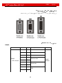
Kinko
FD
FD
Kinco JD 伺服系列使用手册
: SMH
Flange
High
H
Medium
D
Small
S
S
B
A
FD
Kinco JD 伺服系列使用手册
Kinco
5.9 m/s2
FD
Kinco JD 伺服系列使用手册
100mm
100mm
FD
Kinco JD 伺服系列使用手册
FD
Kinco JD 伺服系列使用手册
FD
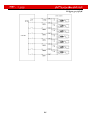
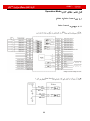
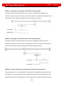
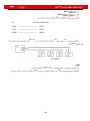
X1
FD 422
COM 1
FD 432
DIN1 – DIN7
FD 622
12.5V-24V Valid Signal
Invalid Signal
5V
OUT1+
OUT1OUT2+
OUT2OUT3
OUT4
COMO
GND
ENCO-Z
ENCO-/Z
ENCO-B
ENCO-/B
ENCO-A
ENCO-/A
FD
AIN1
Kinco JD 伺服系列使用手册
200K
GNDA
AIN2
200K
GNDA
PUL+
PULDIR+
DIR5 – 24V
X2
FD 422
24VS /GNDS
FD 432
24VB/GNDB
FD 622
RB+ & RBX3
FD 422
U & V & W & PE
L&N
RB+ & RB-
FD 432 or FD 622
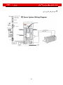
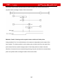
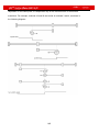
X4
FD 422
BUS
RS 485
FD 422
RS 232
RS 232
FD 432
INCODER IN
FD 432
FD 622
X5
FD 622
X6
FD 422
RS 232
RS 232
FD
Kinco JD 伺服系列使用手册
FD 432
INCODER IN
FD 622
X7
R&S&T
CD 432
FD 432
CD 622
FD 622
RB+ & RBDC+ & DC-
DC
FD
Kinco JD 伺服系列使用手册
FD
Kinco JD 伺服系列使用手册
FD
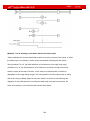
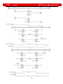
X1
FD
FD
Kinco JD 伺服系列使用手册
FD
Kinco JD 伺服系列使用手册
FD
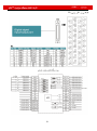
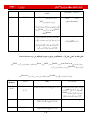
X4~X6
D-SUB
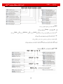
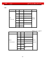
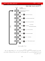
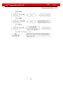
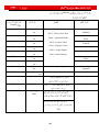
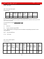
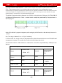
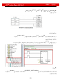
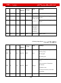
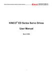
(RS485/CAN) X4
RS485:
Name
Pin
Signal
Descriptions
1
NC
N/A
5
GND
Signal ground
6
+5V
Power
2
RX
7
/RX
3
TX
8
/TX
4
NC
9
NC
RS485
Receive data
(9-Pin female)
Send data
N/A
Function
RS485
interface
FD
Kinco JD 伺服系列使用手册
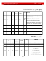
CAN:
Name
Pin
Signal
Descriptions
1
NC
5
NC
6
NC
2
CAN_L
CAN_L
7
CAN_H
CAN_H
3
GND
Signal ground
8
NC
4
NC
9
NC
CAN
(9-Pin male)
Function
CAN bus
interface
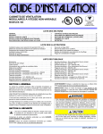
(RS232) X5
Name
Pin
Signal
Descriptions
1
NC
N/A
2
TX
Send data
3
RX
Receive data
4
NC
N/A
5
GND
Signal ground
6
NC
7
NC
8
NC
9
NC
RS232
Function
RS232
(9-Pin female)
interface
N/A
N/A
FD
Kinco JD 伺服系列使用手册
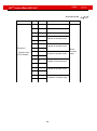
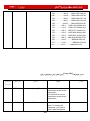
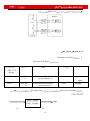
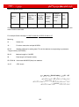
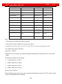
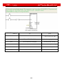
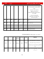
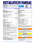
(Encoder in) X6
Name
Pin
Signal
Descriptions
1
+5V
5V output
9
GND
0V
8
PTC_IN PTC of motor input
2
A
10
/A
3
B
Encoder in
11
/B
(Double rows
15-Pin female)
4
Z
12
/Z
5
U
13
/U
6
V
Function
A phase of encoder input
B phase of encoder input
Z phase of encoder input
U phase of encoder input
V phase of encoder input
14
/V
7
W
15
/W
W phase of encoder input
Motor
encoder
input
FD
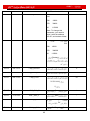
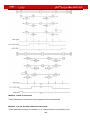
F007
Error
Error
Kinco JD 伺服系列使用手册
Error
Error
FD
Kinco JD 伺服系列使用手册
MODE
UP
DOWN
SET
Enabled Status
Higher/Lower 16Bits
P..L
n..L
Pn.L
Error
▼
▲
FD
9999
Kinco JD 伺服系列使用手册
(Decimal)
(hexadecimal)
-9999
FD
Kinco JD 伺服系列使用手册
real-time
real-time
FD
Kinco JD 伺服系列使用手册
10,000
F003 MODE
MODE
SET
SET
SET
▲
d3.35
MODE
▲
9000
(decimal)
“271.0”
SET
▲
(hexadecimal)
1000 RPM/-1000 RPM
SET
F000
SET
MODE
SET
d0.02 ▲
MODE
▲
SET
1000rpm
▼
-1000rpm
SET
FD
Kinco JD 伺服系列使用手册
Kinco Servo
www.Kinco.cn
Kinco Servo
CANopen
RS 232
FD
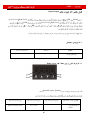
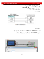
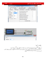
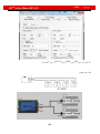
Kinco Servo
RS 232
PC
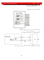
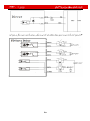
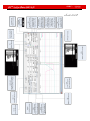
FD Servo RS232 Interface(X5)
RxD 2 ----------------------------------
TXD 2
TxD 3 ----------------------------------
RXD 3
GND 5 ----------------------------------
GND 5
CANopen
FD
PEAK
Kinco JD 伺服系列使用手册
LPT USB
PEAK
CANopen
Pecan
FD Servo CAN Interface(X4)
CAN_L 2 ---------------------------------- CAN_L 2
CAN_H 7 ---------------------------------- CAN_H 7
Kinco Server
Kinco Servo
Kinco Servo
FD
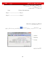
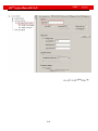
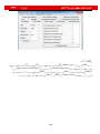
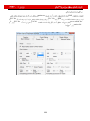
Kinco JD 伺服系列使用手册
RS 232
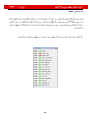
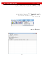
Communication Way
Next
Next
CAN
CAN
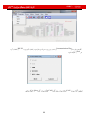
FD
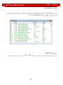
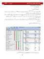
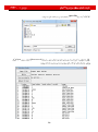
ID Driver Baudrate CAN
Kinco JD 伺服系列使用手册
Property
Comm Status
Comm Status
Driver ID Baudrate
CAN
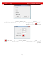
FD
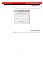
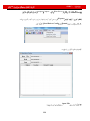
Comm
Kinco JD 伺服系列使用手册
“Comm Status:Open COM1 38400”
Online
Comm Status
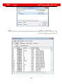
Kinco Server
“Comm Status:Open 500K Bit/S”
Online Kinco Server
Status
CAN
FD
Kinco JD 伺服系列使用手册
FD
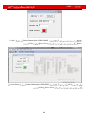
Kinco JD 伺服系列使用手册
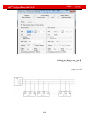
Kinco Servo
File
Computer
Driver
Motor
Extend
Property
FD
Kinco JD 伺服系列使用手册
Basic Operate
Kinco Servo
DIN3
DIN1
Default
Speed Mode
100R.P.M
SpeedDemand_RPM
FD
Kinco JD 伺服系列使用手册
Control Loop
Kinco
FD
FD
Kinco JD 伺服系列使用手册
I/O
I/O
I/O
I/O
FD
Kinco JD 伺服系列使用手册
Kinco Servo
DIN4
Reset
DIN2
DIN5 DIN3 DIN1
OUT2
Driver Enable
DIN1
OK
Driver
I/O
I/O
Save Control Parameters
Initialize/Save
FD
Kinco JD 伺服系列使用手册
FD
Kinco JD 伺服系列使用手册
Oparation Mode
FD
Kinco JD 伺服系列使用手册
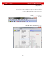
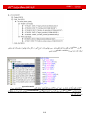
Data Object
FD
subindex index
KincoServo
“Basic
“CANopen baudrate”
Operate”
“add”
“Basic Operate”
Driver
Data Object
“Find next”
“baudrate” in
“Find what”
2F81 index
“CAN_Baudrate”
FD
Kinco JD 伺服系列使用手册
“Basic operate”
“del”
“help”
FD
Kinco JD 伺服系列使用手册
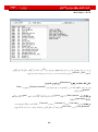
Driver Config
RS 232
KincoServo
“1234”
“Reboot driver”
“User_Secret”
“Save all control parameters”
“Driver->Initialize/Save”
(Reboot)
(“User_Secret”)
reboot save
FD
Kinco JD 伺服系列使用手册
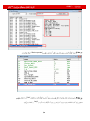
ECAN Setting (CAN open POD Setting)
CANOPEN
FD
Kinco JD 伺服系列使用手册
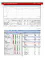
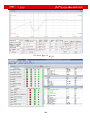
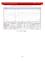
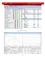
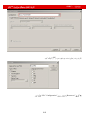
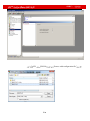
Toolbar
Menu Bar / Driver / Oscilloscope
FD
Kinco JD 伺服系列使用手册
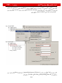
62.5 us
Scanrate
Condition Trigger
Pointer Offset
100 dec
Number of Value
Dec 100 dec
Trigger Signal
amp
FD
Kinco JD 伺服系列使用手册
Falling edge trigger
Object
Continue
Start
Condition Trigger
Reread
a.csv
Export
Import
Object
Offset
Unit
Ch Id
Cursor2 Cursor1
Time
FD
Kinco JD 伺服系列使用手册
FD
Kinco JD 伺服系列使用手册
FD
Kinco JD 伺服系列使用手册
FD
Kinco JD 伺服系列使用手册
LED
FD
Kinco JD 伺服系列使用手册
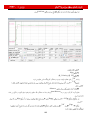
Error History
FD
Driver Accumulated
Control Panel
F007 F000
FD
Kinco JD 伺服系列使用手册
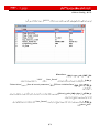
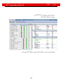
Initialize/Save
Driver Property
FD
Kinco JD 伺服系列使用手册
Default
FD
PC
LED
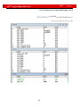
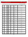
Suitable Servo
Motor Model
LED Code:d4.19
FD422
FD432
FD622
Display FFF.F if not enable (CD120 displays FF)
K@
404.b
Do not configure motor
Display 800.0 if enable (CD120 displays 16)
K0
304.b
SMH60S-0020-30A■K-3LK□
√
K1
314.b
SMH60S-0040-30A■K-3LK□
√
K2
324.b
SMH80S-0075-30A■K-3LK□
√
K3
334.b
SMH80S-0100-30A■K-3LK□
√
K4
344.b
SMH110D-0105-20A■K-4LK□
√
K5
354.b
SMH110D-0125-30A■K-4LK□
√
K6
364.b
SMH110D-0126-20A■K-4LK□
√
K7
374.b
SMH110D-0126-30A■K-4HK□
√
K8
384.b
SMH110D-0157-30A■K-4HK□
√
K9
394.b
SMH110D-0188-30A■K-4HK□
√
KB
424.b
SMH130D-0105-20A■K-4HK□
√
√
KC
434.b
SMH130D-0157-20A■K-4HK□
√
√
KD
444.b
SMH130D-0210-20A■K-4HK□
√
FD
Kinco JD 伺服系列使用手册
KE
454.b
SMH150D-0230-20A■K-4HK□
E0
304.5
SME60S-0020-30A■K-3LK□
√
E1
314.5
SME60S-0040-30A■K-3LK□
√
E2
324.5
SME80S-0075-30A■K-3LK□
√
S0
305.3
130D-0105-20AAK-2LS
√
S1
315.3
130D-0157-20AAK-2LS
√
S2
325.3
130D-0157-15AAK-2LS
√
S3
335.3
130D-0200-20AAK-2HS
√
S4
345.3
130D-0235-15AAK-2HS
√
F8
384.6
Note:
√
85S-0045-05AAK-FLFN
√
85S-0045-05AAK-FLFO-KT
√
■=A: No brake
=B: With brake
√
□= H:Direct cable connector
√:Recommended
=N:HFO series standard connector
of Servo and Motor
= C:YL22
series standard connector
= M:2*M17
series Intercontec connector
Configuration
FD
Kinco JD 伺服系列使用手册
800.0 FFF.F
restart
FD
1
d4.00
SET
303.0
Kinco JD 伺服系列使用手册
D4.19
reset
restart
Kinco Servo
Menu/Driver/ Control Panel/F004
Restart
Kinco Servo
PC
Motor Num
F004
Restart
00
reset
F004
restart
Motor Num D4.19
Save motor parameters
reset
Initialize/Save
FD
Kinco JD 伺服系列使用手册
Trial Operation
Flange
Runing
Down Up
Trial Operation
Trial Operation
F006
F006
Trial Operation
FD
Kinco JD 伺服系列使用手册
Operating Procedure
Error
Trial Operation
Speed Dimand RPM
Down
Up
.
STO
d4.18
Group F004
MODE
d0.02
Group F001
MODE
Group F001
MODE
d6.40 Default
d6.15
Down
d6.31
d6.25
abc.d
–Speed +Speed Demand RPM
trial operation
SET
Down Up
Demand RPM
Trail Operation
FD
Kinco JD 伺服系列使用手册
Trial Operation
FD
Kinco JD 伺服系列使用手册
F000
F004
d4.00
d5.00 d3.00 D2.00
d5.00 d3.00 D2.00
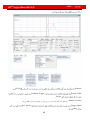
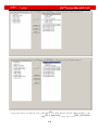
F001/F002/F003/F004/F005
F000
Range
Default
D0.00
60600008
Operatin_Mode
(CW/CCW)
D0.01
2FF00508
Control_word_Easy
Error
(P/D)
FD
Kinco JD 伺服系列使用手册
Enable
D0.02
2FF00910
SpeedDemand_RPM
d3.28
0
D0.03
CMD_q
2047
d3.30
D0.04
2FF00A10
Vc_Loop_BW
D0.05
2FF00B10
Pc_Loop_BW
[Hz]
[Hz]
d2.00
D0.06
2FF00C10
Tuning_Start
(Real _ Time Display
D1.00
2FF00F20
Soft_Version_LED
D1.01
2FF70020
Time_Driver
D1.02
2FF01008
Motor_llt_Rate
Group F001
(S)
Ratio Of Real itt to the Maximum itt of
a motor
FD
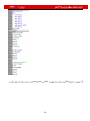
D1.03
60F61210
Kinco JD 伺服系列使用手册
Motor_llt_Real
Display
D1.04
2FF01108
Driver_llt_Rate
D1.05
60F61010
Driver_llt_Real
D1.06
2FF01208
Chop_Power_Rate
D1.07
60F70D10
Chop_Power_Real
D1.08
60F70B10
Temp_Device
D1.09
60790010
Real_DCBUS
D1.10
60F70C10
Ripple_DCBUS
D1.11
60FD0010
Din_Status
D1.12
D1.13
25020F10
Fluctuating Value of the Bus Voltage
(VPP)
Analoge1_Out
Analoge2_Out
26010010
D1.16
D1.17
DC
Dout_Status
D1.14
D1.15
Ratio Of Real itt to the Maximum itt of
a Driver
60410010
Error_State
Error State
Error_State2
Error State Word 2
Status_Word
Driver status word
bit0:Ready to switch on
bit1:Switch on
bit2:Operation enable
bit3:Falt
FD
Kinco JD 伺服系列使用手册
bit4:Voltage Disable
bit5:Quick Stop
bit6:Switch on disable
bit7:Warning
bit8:Reserved
bit9:Reserved
bit10:Target reach
bit11:Internal limit active
bit12:Step.Ach./V=0/Hom.att.
bit13:Foll.Err/Res.Hom.Err.
bit14:Commutation Found
bit15:Referene Found
D1.18
60610008
Operation_Mode_Buff
D1.19
60630020
Pos_Actual
D1.20
60FB0820
Pos_Error
D1.21
25080420
Gear_Master
D1.22
25080520
Gear_Slave
D1.23
25080C10
Master_Speed
Position Following Error
Master Axis
(pulse/mS)
D1.24
25080D10
Slave_Speed
D1.25
606C0010
Real_Speed_RPM
(pulse/mS) slave
rpm
[R.P.M]
200 Internal Sampling
D1.26
60F91910
Real_Speed_RPM2
[R.P.M]
200 Internal Sampling
D1.27
60F91A10
Speed_1ms
(inc/1ms) [R.P.M]
FD
Kinco JD 伺服系列使用手册
Internal Sampling
D1.28
60F60C10
CMD_q_Buff
D1.29
60F61710
L_q
D1.30
60F90E10
K_Load
D1.31
30100420
Z_Capture_POS
Position Data Captured by encoder
index signals
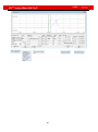
Control Loop
Group F002
Range
Defa
ult
D2.00
2FF00108
Store_Loop_Data
Setup
Setup
D2.01
60F90110
Kvp
D2.02
60f90210
Kvi
D2.03
60f90308
Notch_N
Error
Notch/Filtering
Notch
D2.04
60F90408
Notch_On
Notch Filter
Disable Enable
Trap Filter
Disable
Trap Filter
Enable
0
/
FD
D2.05
60F90508
Kinco JD 伺服系列使用手册
Speed_Fb_N
F= Speed_Fb_N*20+100
500Hz
Filter Bandwidth
D2.06
60F90608
Speed_Mode
D2.07
60FB0110
Kpp
D2.08
60FB0210
K_Speed_FF
256
D2.09
60FB0310
K_Acc_FF
7FF.
F
Low-pass Filter
Position Loop Kpp
Feedforward
D2.10
2FF00610
Profile_Acce_16
(rps/s) Trapzodial
D2.11
2FF00710
Profile_Dece_16
(rps/s) Trapzodial
D2.12
60F60110
Kcp
D2.13
60F60210
Kci
D2.14
60730010
CMD_q_Max
D2.15
60F60310
Speed_Limit_Facto
r
D2.16
607E0008
Invert_Dir
D2.17
60F90E10
K_Load
D2.18
60F90B10
Kd_Virtual
Error
Indicates the Kd of Observers
1000
610
FD
Kinco JD 伺服系列使用手册
D2.19
60F90E10
Kp_Virtual
Indicates the Kp of Observers
D2.20
60F90D10
Ki_Virtual
Indicates the Ki of Observers
D2.21
60F91010
Sine_Amplitude
auto tuning
D2.22
60F91110
Tuning_Scale
Data
Auto Tuning
.
D2.23
60F91210
Tuning_Filter
D2.24
60800010
Max_Speed_RPM
auto tuning
tuning
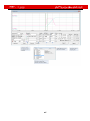
Pattern Operation
D3.00
2FF00108
Store_Loop_Date
D3.01
20100310
Din1_Function
Group F003
1
000.1:
0
/
000.1
/
000.2
/
000.4
/
000.2:
D3.02
20100410
Din2_Function
000.4:
D3.03
20100510
Din3_Function
000.8:
Operation
p
FD
D3.04
20100610
Kinco JD 伺服系列使用手册
Din4_Function
001.0:
000.8
/
001.0
/
002.0
/
004.0
/
0
/
0
/
0
/
002.0:
D3.05
20100710
Din5_Function
004.0: Homing
D3.06
20100810
Din6_Function
008.0: Reverse speed demand
010.0: Internal speed control 0
D3.07
20100910
Din7_Function
020.0: Internal speed control 1
800.1: Internal speed control 2
040.0: Internal position control 0
080.0: Internal position control 1
800.2: Internal position control 2
800.4 Multi Din 0
800.8 Multi Din 1
801.0 Multi Din 2
802.0 Gain switch 0
804.0 Gain switch 1
100.0: Quick stop
200.0: Start homing
400.0: Activate command
DinX_Function(X is 1-7)
D3.08
2FF00D10
Dio_Polarity
D3.09
2FF00D10
Dio_Simulate
D3.10
20000008
Switch_On_Auto
force
Automatically locks motors when drivers
are powered on
0: No control
FD
Kinco JD 伺服系列使用手册
1: Automatically locks motors when
drivers are powered on
D3.11
20100F10
Dout1_Function
000.1: Ready
000.1
/
000.0
/
00a.4
/
000.8
/
000.0
/
-4
/
-3
/
0
/
000.2: Error
D3.12
20101010
Dout2_Function
000.4: Position reached
000.8: Zero velocity
D3.13
20101110
Dout3_Function
001.0: Motor brake
002.0:Velocity reached
D3.14
20101210
Dout4_Function
004.0: Index
008.0: The maximum speed obtained in
the torque mode
010.0: PWM ON
020.0: Position limiting
040.0: Reference found
080.0: Reserved
100.0: Multi Dout 0
200.0: Multi Dout 1
D3.15
20101310
Dout5_Function
400.0: Multi Dout 2
Note:DoutX_Function(X is 1-5) is used to
define functions of the digital outputs.
D3.16
20200D08
Din_Mode0
invalid
D3.17
20200E08
Din_Mode1
D3.18
20200910
Din_Speed0_RPM
If a digital input is defined as Operation
mode control,then this operation mode is
selected when the input signal is valid
0 R.P.M
FD
Kinco JD 伺服系列使用手册
D3.19
20200A10
Din_Speed2_RPM
1 R.P.M
0
/
D3.20
20200B10
Din_Speed2_RPM
2 R.P.M
0
/
D3.21
20200C10
Din_Speed3_RPM
3 R.P.M
0
/
D3.22
25020110
Analog1_Filter
Used to smooth the input analog signals
5
F (Filter Frequency) = 4000/ (2π*
Analog1_Filter)
Τ (Time Constant) = Analog1_Filter/4000
(S)
D3.23
25020210
Analog1_Dead
Sets dead zone data for external analog
signal 1
0
D3.24
25020310
Analog1_Offset
Sets offset data for external analog signal
1
0
D3.25
25020410
Analog2_Filter
Used to smooth the input analog signals
5
Filter frequency: f=4000/(2π*
Analog1_Filter)
Time Constant: T = Analog1_Filter/4000
(S)
D3.26
25020510
Analog2_Dead
Sets dead zone data for external analog
signal 2
0
D3.27
25020610
Analog2_Offset
Sets offset data for external analog signal
2
0
D3.28
25020708
Analog_Speed_Con
Chooses analog-speed channels
0
0: Invalid analog channel
1: Valid analog channel 1 (AIN1)
2: Valid analog channel 2 (AIN2)
Valid mode -3 and 3
D3.29
25020A10
Analog_Speed_Factor
Sets the proportion between analog
signals and output speed
D3.30
25020808
Analog_Torque_Con
Chooses analog-torque channels
0: Invalid analog channel
1000
0
FD
Kinco JD 伺服系列使用手册
1: Valid analog channel 1 (AIN1)
2: Valid analog channel 2 (AIN2)
Valid mode 4
D3.31
25020B10
Analog_Torque_Factor
D3.32
25020908
Alalog_MaxT_Con
Sets the proportion between analog
signals and output speed (current)
0: No control
1000
0
1: Max. torque controlled by AIN 1
2: Max. torque controlled by AIN 2
D3.33
25020C10
Analog_MaxT_Factor
Indicates the max torque factor on analog
signal control
8192
D3.34
25080110
Gear_Factor
Indicates the numerator to set electronic
gears when the operation mode is -4
1000
D3.35
25080210
Gear_Divider
Indicates the denominator to set
electronic gears when the operation
mode is -4
1000
D3.36
25080308
PD_CW
Pulse mode control
1
0...CW/CCW
1...Pulse/Direction
2...Incremental encoder
Note:After changing this parameter,it
needs to save by d2.00/d3.00/d5.00 and
then reboot driver.
D3.37
25080610
PD_Filter
To flat the input pulse.
3
Filter frequency: f=1000/(2π* PD_Filter)
Time constant: T = PD_Filter/1000
Unit: S
Note: If you adjust this filter parameter
during the operation, some pulses may
be lost.
D3.38
25080810
Frequency_Check
D3.39
25080910
PD_ReachT
Indicates the limitation on pulse input
frequency (k Hz)
600
Indicates the position reached time
window in the pulse mode
10
FD
Kinco JD 伺服系列使用手册
Unit: mS
D3.40
2FF10108
Din_Position_Select_L
Select which internal position will
0
be set.(The range of L is 0-7)
Din_Pos0
Din_Pos1
Din_Pos2
Din_Pos3
Din_Pos4
Din_Pos5
Din_Pos6
Din_Pos7
D3.41
2FF10210
Din_Position_M
Refer to d3.42
0
D3.42
2FF10310
Din_Position_ N
The position of internal position set in
Din_Position_Select_L
0
Din_Pos =
Din_Position_M*10000+Din_Position_N
D3.43
20200F10
Din_Control_Word
Absolute positioning/Relative
2F
positionin gsetting
2F:Absolute positioning
4F:Relative positioning
Note:This parameter needs to save and
reboot driver after change.
D3.44
20201810
Din_Speed4_RPM
rpm 4
0
D3.45
20201910
Din_Speed5_RPM
rpm 5
0
D3.46
20201A10
Din_Speed6_RPM
rpm 6
0
D3.47
20201B10
Din_Speed7_RPM
rpm
0
FD
Kinco JD 伺服系列使用手册
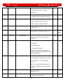
Group F004
D4.00
2FF00308
Store_Motor_Data
D4.01
64100110
Motor_Num
Host computer (ASCII code)
(hexadecimal)
numerical display
“00”..... ..... ...303.0
About the motor number please refer to chapter
6.1.1.
Note: 1.Set the motor parameters refer to chapter
6 before operating.
2.It must use capital letter when set this parameter
by PC.
3.It needs to save by d4.00 and reboot driver after
changing this parameter.
D4.02
64100208
Feedback_Type
Type of encoders
001.1: Differential ABZ and differential UVW
signals
001.0: Differential ABZ and UVW signals of TTL
000.1: ABZ of TTL and differential UVW signals
000.0: ABZ of TTL and UVW signals of TTl
D4.03
64100508
Motor_Poles
Number of motor poles pairs
[2p]
D4.04
64100608
Commu_Mode
Searching excitation mode
D4.05
64100710
Commu_Curr
Searching excitation current
[dec]
D4.06
64100810
Commu_Delay
Delay in searching excitation
[mS]
D4.07
64100910
Motor_llt_l
Indicates current settings on overheat protection of
motors
FD
Kinco JD 伺服系列使用手册
Ir[Arms]*1.414*10
D4.08
64100A10
Motor_llt_Filter
Indicates time settings on overheat protection of
motors
Time: N*256/1000 Unit: S
D4.09
64100B10
Imax_Motor
Indicates max peak current of motors
I[Apeak]*10
D4.10
64100C10
L_Motor
Indicates phase inductance of motors
L[mH]*10
D4.11
64100D08
R_Motor
Indicates phase resistance of motors
R[Ω]*10
D4.12
64100E10
Ke_Motor
Indicates the reverse electromotive force of motors
Ke[Vp/krpm]*10
D4.13
64100F10
Kt_Motor
Indicates the torque coefficient of motors
Kt[Nm/Arms]*100
D4.14
64101010
Jr_Motor
Indicates the rotor inertia of motors
Jr[kgm^2]*1 000 000
D4.15
64101110
Brake_Duty_Cycle
Indicates the duty cycle of contracting brakes
0~2500[0…100%]
D4.16
64101210
Brake_ Delay
Indicates the delay time of contracting brakes
Default value: 150 ms
D4.17
64101308
Invert_Dir_Motor
D4.18
64101610
Motor_Using
Indicates the rotation direction of motors
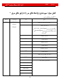
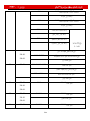
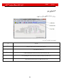
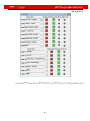
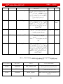
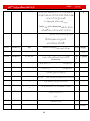
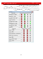
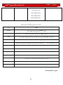
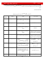
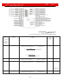
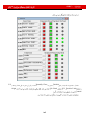
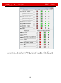
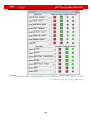
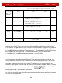
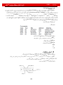
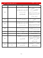
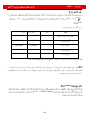
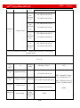
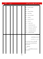
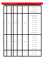
Current using motor type.
PC Software Numeric Display Model
"K0"....................304.B…....SMH60S-0020-30
"K1"...................314.B…….SMH60S-0040-30
"K2"...................324.B…….SMH80S-0075-30
"K3"...................334.B…….SMH80S-0100-30
"K4"...................344.B……SMH110D-0105-20
"K5"...................354.B……SMH110D-0125-30
"K6"..................364.B….....SMH110D-0126-20
"K7"……….......374.B…….SMH110D-0126-30
FD
Kinco JD 伺服系列使用手册
"K8"…………...384.B.........SMH110D-0157-30
"K9"..................394.B…....SMH110D-0188-30
KB"……..……...424.B…....SMH130D-0105-20
“KC"…………...434.B…….SMH130D-0157-20
“KD"…………...444.B…….SMH130D-0210-20
“KE"…………...454.B…....SMH150D-0230-20
"S0"………...305.3…..130D-0105-20AAK-2LS
"S1"..............315.3…..130D-0157-20AAK-2LS
"S2"………...325.3….130D-0157-15AAK-2LS
"S3"..............335.3….130D-0200-20AAK-2HS
"S4"..............345.3….130D-0235-15AAK-2HS
"F8"………...384.6…..85S-0045-05AAK-FLFN
"E0"..............304.5………..SME60S-0020-30
"E1"..............314.5……........SME60S-0040-30
"E2".................324.5…………..SME80S-0075-30
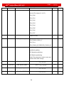
Group F005
Default
D5.00
2FF00108
Store_Loop_Data
D5.01
100B0008
ID_Com
1: Stores all control
parameters except motor
parameters
10: Initializes all control
parameters except motor
parameters
0
Station No. of Drivers
1
Note: To change this
parameter, you need to
save it with the address
FD
Kinco JD 伺服系列使用手册
“d5.00”, and restart it later.
D5.02
2FE00010
RS232_Bandrate
Set the baud rate of RS232
port
540
19200
270
38400
90
115200
270
Note: To change this
parameter, you need to
save it with the address
“d5.00”, and restarts it later.
D5.03
2FE10010
U2BRG
RS
270
Baudrate
232
540
270
90
19200
384000
115200
Restart
D5.04
60F70110
Chop_Resistor
0
D5.05
60F70210
Chop_Power_Rated
0
D5.06
60F70310
Chop_Filter
60
N*256/1000
S
D5.07
25010110
ADC_Shift_U
Data
/
D5.08
25110210
ADC_Shift_V
Data
/
D5.09
30000110
Voltage_200
ADC Original
/
DC
D5.10
30000210
Voltage_360
ADC Digital
Data
/
FD
Kinco JD 伺服系列使用手册
DC
D5.11
60F60610
Comm_Shift_UVW
D5.12
26000010
Error_Mask
D5.13
60F70510
Relay_Time
/
Error Masks
FFF.F
150
ms
D5.14
2FF00408
Key_Address_F001
/
D5.15
65100B08
RS232_Loop_Enable
0
N
D5.16
2FFD0010
User_Secret
FD
Kinco JD 伺服系列使用手册
Input/Output
Low Level High Level
FD
COM
Low Level High Level
BR
D3.08
Dio_Polarity
I/O
Normally Open Default
Normally
Close
Kinko
FD
Kinco JD 伺服系列使用手册
Normally
Open
(DIN1)
S1
DIN1
Set to 1 (DIN1 Selected)
S1
DIN1
FD
Polarity
Kinco JD 伺服系列使用手册
LED
DIN6 DIN5 LED
I/O Port
FD
Normally Open
Normally Close
DIN6 DIN5
FD
Kinco JD 伺服系列使用手册
Display
D3.09
Dio_Simulate
Dio_Simulate
0: No input signal is simulated, and no
output signal is compulsorily outputted
1: Input signal is simulated, and output
signal is outputted compulsorily
Other: Check the current status
FD
Kinco JD 伺服系列使用手册
DIN1
DIN1
DIN1
DIN1
DIN1
Display
D1.11
Din_Status
Default
Display
D3.01
Din1_Function
000.1: Driver enable
000.2: Driver fault reset
D3.02
Din2_Function
000.4: Operation mode control
000.1 (Driver
Enable)
000.2 (Driver Fault
rest)
000.8: P control for velocity loop
D3.03
Din3_Function
001.0: Position positive limit
000.4 (Operation
Mode Control)
FD
D3.04
Din4_Function
Kinco JD 伺服系列使用手册
002.0: Position negative limit
004.0: Homing signal
D3.05
Din5_Function
D3.06
Din6_Function
000.8 (P Control
For Velocity loop)
008.0: Reverse speed demand
001.0 (Position
Positive Limit)
010.0: Internal speed control 0
020.0: Internal speed control 1
D3.07
Din7_Function
800.1: Internal speed control 2
040.0: Internal position control 0
002.0 ( Position
Negative Limit)
004.0 (Homing
Signal)
080.0: Internal position control 1
800.2: Internal position control 2
800.4 Multi Din 0
800.8 Multi Din 1
801.0 Multi Din 2
802.0 Gain switch 0
804.0 Gain switch 1
100.0: Quick stop
200.0: Start homing
400.0: Activate command
Note:DinX_Function(X is 1-7) is used to define the
function of digital inputs.
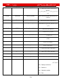
Disable
Driver Anable
Driver Fault Reset
Operation Mode Control
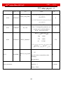
Used to cancel the function of this digital input.
By default, the driver enable signal is valid, and the motor shaft is locked.
Signals on the rising edge are valid, and alarms are cleared.
To switch between two operation modes.
You can freely determine the operation modes corresponding to valid signals
FD
Kinco JD 伺服系列使用手册
and invalid signals by performing settings through d3.16 Din_Mode0 (choose 0
for operation mode) of Group F003 and Din_Mode1 (choose 1 for operation
mode) of Group F003.
P Control For Velocity Loop
Indicates the control on stopping integration in velocity loop. The control is
applied in the occasion where high-speed system stop occurs, but
overshooting is not expected.
Note: In the “-3” mode, if the signal is valid, fixed errors occur between the
actual speed and target speed.
Position Positive Limit
Indicates the limit of forward running of motors (normally closed contact by
default).
By default, the driver regards position positive limits as valid, and polarity can
be modified to adjust to normally open switches.
Position Positive Limit
Indicates the limit of inverted running of motors (normally closed contact by
default).
By default, the driver regards position negative limits as valid, and polarity can
be modified to adjust to normally open switches.
Homing Signal
To find origins of motors.
Reverse Speed Demand
To reverse the target speed in the speed mode ("-3" or “3”).
Internal Speed Control 0
To control internal multiple speeds.
Internal Speed Control 1
Note: For details, see Section 7.5 Internal Multi-Speed Control.
Internal Speed Control 2
Internal Position Control 0
To control internal multiple positions.
Internal Position Control 1
Note: For details, see Section 7.4 Internal Multi-Position Control.
Internal Position Control 2
Multi Din 0
Multi Din 1
To switch multiple electronic gear
Multi Din 2
Gain Switch 0
To switch multiple gain parameters(P-gain of velocity loop,i-gain of velocity
loop,p-gain of position loop)
Gain Switch 1
Quick Stop
When the signal is valid, the motor shaft releases.
After the signal is removed, the driver requires re-enabling.
FD
Start Homing
Activate Command
Kinco JD 伺服系列使用手册
When the rising edge of the signal is detected,it will start homing command.
When the rising edge of the signal is detected,it will activate the internal
position control
Driver Enable
“driver enable”
DIN1
Display
D3.01
Din1_Function
Set to 000.1
D3.00
Store_Loop_Data
Set To 1
D3.01 – d3.07
DinX_Function (1-7)
None of the digital input port can be
set to 000.1, that is, the Enable
function is not controlled by any digital
input port.
D3.10
Switch_On_Auto
Set to 1
D3.00
Store_Loop_Data
Set to 1
Display
FD
Kinco JD 伺服系列使用手册
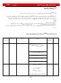
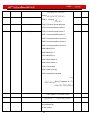
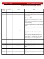
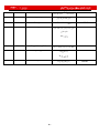
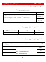
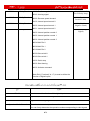
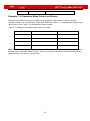
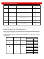
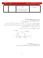
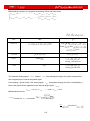
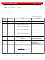
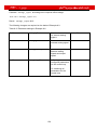
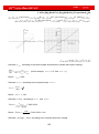
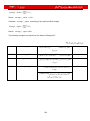
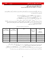
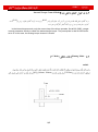
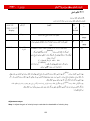
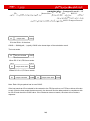
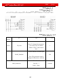
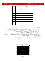
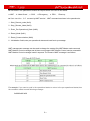
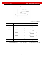
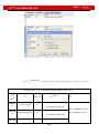
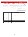
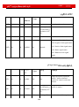
Example 7-4: Disabling Position Positive/Negative Limit Settings
When the driver is delivered, the DIN5 of the motor is the position positive limit and DIN6 is the position
negative limit by default. If there are no external position positive/negative limit switches, this function
must be disabled so that the servo driver can work properly. Table 7-12 describes the setup method.
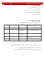
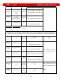
Table 7-12: Disabling position positive/negative limit settings
Numeric
Display
Variable Name
Parameter Settings
d3.05
Din5_Function
Change the default value 001.0
(position positive limit) to 000.0
d3.06
Din6_Function
Change the default value 002.0
(position negative limit) to 000.0
FD
d3.00
Store_Loop_Data
Kinco JD 伺服系列使用手册
Set to 1
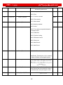
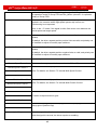
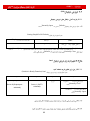
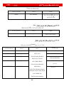
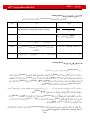
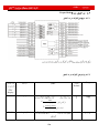
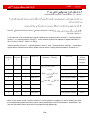
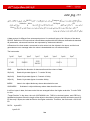
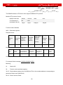
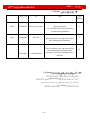
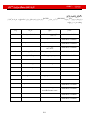
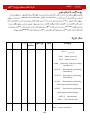
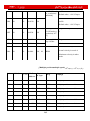
Example 7-5: Operation Mode Control on Drivers
Requirements: Defines the input port DIN3 as the operation mode control on drivers, and the
operation mode is “-4” (pulse control mode) when DIN3 fails, and is “-3” (instantaneous speed mode)
when DIN3 is valid. Table 7-13 describes the setup method.
Table 7-13 Settings on operation mode control on drivers
Numeric Display
Variable Name
Parameter Settings
d3.03
Din3_Function
Set to 000.4
d3.16
Din_Mode0
Set to 0.004 (-4)
d3.17
Din_Mode1
Set to 0.003 (-3)
d3.00
Store_Loop_Data
Set to 1
Note: If the driver is required to operate in some mode with power on, one of the digital input must be
set as function “Operation Mode Control”. Then you can set the operation modes that require in the
parameters d3.16 or d3.37 in Group F003.
FD
Kinco JD 伺服系列使用手册
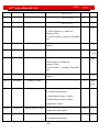
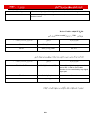
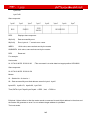
(DI)
NPN
FD
Kinco JD 伺服系列使用手册
PNP
FD
Kinco JD 伺服系列使用手册
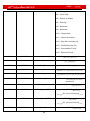
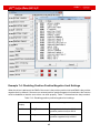
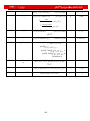
(DO)
Normally Open
Default
Setting Simplified IO Polarity
Display
D3.08
Dio_Polarity
Normally Open
I/O
Dio_Polarity
Default
Normally Close
Out1
(Default is Ready Function) Out1
Input/output port selection
Set to 0 (Output port
selected)
Channel selection
Set to 1 (OUT1
selected)
Out1
Normally Close
Out1
Normally Open
FD
Kinco JD 伺服系列使用手册
I/O
D3.09
Dio_Simulate
( DO )
D1.12
Dout_Status
Default
Default
D3.11
Dout1_Function
000.1 Ready
000.1 (Ready)
D3.12
Dout2_Function
000.2 Error
000.2 (Error)
D3.13
Dout3_Function
000.4 Position Reached
00a.4 (Position Reached /
Velocity Reached)
000.8 Zero Velocity
D3.14
Dout4_Function
001.0 Motor Brake
002.0 Velocity Reached
D3.15
Dout5_Function
004.0 Index
008.0 The Maximum Speed
Obtained in the Torque Mode
010.0 PMW ON
020.0 Position limiting
000.8 (Zero Velocity)
FD
Kinco JD 伺服系列使用手册
040.0 Refrence Found
080.0 Reserved
100.0 Multi Dout 0
200.0 Multi Dout 1
400.0 Multi Dout 2
Disable
Cancel
Ready
Error
Position Rached
In the -4 Mode of Pulse Control , the Target Position Data Keeps
Zero Velocity
Enable
Motor Brake
Velocity Rached
Index
Max.Velocity limit
PWM ON
Motor Limiting
Refrence Found
Homing is Finished
Ready
FD
Ready
Kinco JD 伺服系列使用手册
Out1
Ready
D3.11
Dout1_Function
Set to 000.1
D3.00
Store_Loop_Data
Set to 1
FD
Kinco JD 伺服系列使用手册
Out4 Out3
(COMO).
Out7
Out1 NPN
Out7 Out2 Out1
PNP
FD
Kinco JD 伺服系列使用手册
FD
Kinco JD 伺服系列使用手册
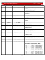
Operation Mode
Mode -4 Pulse Control
Pulse Control
FD
(.
Low Level
FD
Kinco JD 伺服系列使用手册
High Level
Electronic Gear Ratio
Electronic Gear Ratio
Default
Range
Display
D3.34
Gear_Fact
or
Numerator of Electronic
gear 0 in Mode -4
1000
D3.35
Gear_Dri
ver
Denominator of Electronic
gear 0 in mode -4
1000
Electronic Gear
Command pulse input
F1
Command pulse output
F2
Electronic Gear Ratio
FD
Namely: F2=
Kinco JD 伺服系列使用手册
Gear _ Factor
* F1
Gear _ Divider
1:1
2:1
Multi Din 2
Multi Din 1
Multi Din 0
Electronic Gear 0
Electronic Gear 1
Electronic Gear 2
Electronic Gear
03
1
1
1
1
0
0
1
1
0
1
0
1
Electronic Gear 4
Electronic Gear
05
Electronic Gear 6
Electronic Gear 7
Gear_Factor 0
2508+0110
Gear_Divider 0
25080210
Gear_Factor 1
25090110
Gear_Divider 1
25090210
Gear_Factor 2
25090310
Gear_Divider 2
25090410
Gear_Factor 3
25090510
Gear_Divider 3
25090610
Gear_Factor 4
25090710
Gear_Divider 4
25090810
Gear_Factor 5
25090910
Gear_Divider 5
25090A10
Gear_Factor 6
25090B10
Gear_Divider 6
25090C10
Gear_Factor 7
25090D10
Gear_Divider 7
25090E10
FD
Kinco JD 伺服系列使用手册
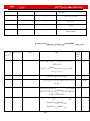
Gear_Divider Gear_Factor Default
Range
Default
Display
D3.36
PD_CW
N/A
(CW/CCW)
(P/D)
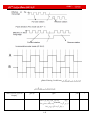
Incremental Encoder
Restart
d3.00
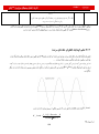
AB
Double Pulse (CW/CCW) Mode (d3.36=0)
FD
Kinco JD 伺服系列使用手册
Pulse Filtering Coefficient
Default
Range
Display
D3.37
PD-Filter
Smooth
Smooth
3
1-32767
FD
Kinco JD 伺服系列使用手册
f=
T=
S
Default
D3.38
Frequency_check
KHz
Default
loading
FD
Kinco JD 伺服系列使用手册
Display
Default
d2.07
Kpp
1000
0~16384
d2.08
K_Velocity_FF
256
0~256
d2.09
K_Acc_FF
32767
32767~10
d0.05
Pc_Loop_BW
0
/
d2.26
Pos_Filter_N
1
/
kpp
Hz
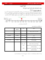
Proportional gain of velocity loop Kvp: If the proportional gain of the velocity loop increases, the
responsive bandwidth of the velocity loop also increases. The bandwidth of the velocity loop is directly
proportional to the speed of response. Motor noise also increases when the velocity loop gain
increases. If the gain is too great, system oscillation may occur.
Integral gain of velocity loop Kvi: If the integral gain of the velocity loop increases, the low-frequency
intensity is improved, and the time for steady state adjustment is reduced; however, if the integral gain
is too great, system oscillation may occur.
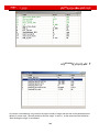
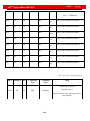
Multiple gains can be defined by DIN with the function “Gain Switch 0” and “Gain Switch 1” as shown
in following table.
Gain Switch 1
0
0
1
Gain Switch 0
0
1
0
Descriptions
Gain 0
Gain 1
Gain 2
Parameters
Name
Address
Kvp of Gain 0
60F90110
Kvi of Gain 0
60F90210
Kpp of Gain 0
60FB0110
Kvp of Gain 1
23400410
Kvi of Gain 1
23400510
Kpp of Gain 1
23400610
Kvp of Gain 2
23400710
Kvi of Gain 2
23400810
Kpp of Gain 2
23400910
FD
1
1
Gain 3
Kinco JD 伺服系列使用手册
Kvp of Gain 3
23400A10
Kvi of Gain 3
23400B10
Kpp of Gain 3
23400C10
If DIN is defined as “Gain Switch” function,then the parameter “PI_Switch” will disable.
Parameter “PI_Point”(60F92808) is used to display the current gain.
Auto-tuning can only be used to set Gain 0.
Vc_Loop_BW and Pc_Loop_BW are only corresponding to Gain 0.Other Gain needs to set by
manual.
“PI_Switch” is used to switch Gain 0 and Gain 1.In mode -4,1 and 3,it will use Gain 1 when “Position
reached” signal is valid,and use Gain 0 when “Position reached” signal is invalid.
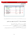
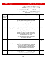
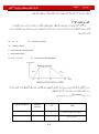
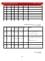
8.1.3 Examples of Pulse Control Mode
In the pulse control mode, follow the steps below to configure a driver:
Step 1: Confirm whether the functions of the driver require enabling through external digital input
ports. To enable the driver through external digital input ports, see Table 6-12 in Example 6-3 for
settings. If it is not necessary to enable the driver through external digital input ports, you can disable
the enabling control function of external digital input ports by referring to Table 6-13 of Example 6-3,
and enable the driver by setting its internal parameters.
Step 2: Confirm whether limit switches are required. By default, the driver operates in the limit status
after being powered on. In this case, the numeric display has limit status display. If there is no limit
switches, please disable the function of limit switches by referring to Example 6-4.
Step 3: Confirm mode switching bits and operation modes by referring to the settings in Example 6-5.
The factory default settings of the driver are as follows: When no signal is inputted on DIN3, the driver
operates in the “-4” mode (pulse control mode).
Step 4: After function configuration on digital input ports, it is required to set parameters such as pulse
modes and electronic gear ratio.
Step 5: Save parameters.
Enable
DIN3
Reset
DIN2
Pulse Control
Enable
DIN1
Operation Mode
FD
Kinco JD 伺服系列使用手册
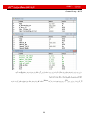
2:1 Electronic gear ratio
Pulse/Direction
Enable
Numeric
Display
d3.01
Din1_Function
000.1 (Driver enable)
d3.02
Din2_Function
000.2 (Fault reset)
d3.03
Din3_Function
000.4 (Operation mode
control )
d3.05
Din5_Function
The default value 001.0
changes to 000.0 (position
positive limits are disabled)
d3.06
Din6_Function
The default value 002.0
changes to 000.0 (position
negative limits are disabled)
d3.16
Din_Mode0
Operation Mode
0.004
invalid
d3.17
Din_Mode1
Operation Mode
0.003
valid
d3.34
Gear_Factor
Indicates the numerator to set
electronic gears in the “-4”
operation mode (pulse control
mode)
Gear_Factor
d3.35
Gear_Divider
Indicates the denominator to set
electronic gears in the “-4”
Gear_Divider
FD
Kinco JD 伺服系列使用手册
operation mode (pulse control
mode)
d3.36
PD_CW
CW/CCW
Default
P/D
(pulse direction)
D3.00
SAVE
Restart
d3.00
Store_Loop_Data
Store_Loop_Data
Driver Power on
DIN3
Enable
Reset
DIN2
Enable
Auto Power-on
Operation
Power on
Enable
Numeric
Display
d3.01d3.07
DinX_ Function
(1~7)
000.1
Enable
d3.02
Din2_Function
000.2 (Error resetting)
d3.03
Din3_Function
000.4 (Control on operation
FD
Kinco JD 伺服系列使用手册
modes for the driver)
d3.05
Din5_Function
The default value 001.0
changes to 000.0 (position
positive limits are disabled)
d3.06
Din6_Function
The default value 002.0
changes to 000.0 (position
negative limits are disabled)
d3.10
Switch_On_Auto
No Control
Power on
d3.16
Din_Mode0
Set to 0.004 (-4) mode
invalid
d3.17
Din_Mode1
(pulse control mode)
Set to 0.003 (-3) mode
valid
(instantaneous speed mode)
d3.34
Gear_Factor
Indicates the numerator to set
electronic gears in the “-4”
operation mode (pulse control
mode)
Gear_Factor
d3.35
Gear_Divider
Indicates the denominator to set
electronic gears in the “-4”
operation mode (pulse control
mode)
Gear_Divider
d3.36
PD_CW
0: Double pulse (CW/CCW) mode
Default value is 1
1. Pulse direction (P/D) mode
(pulse direction)
Note: To change this parameter,
you need to save it with the address
“d3.00”, and restarts it later.
FD
d3.00
Store_Loop_Data
Kinco JD 伺服系列使用手册
Store_Loop_Data
Speed Mode
Kpp
d2.11 d2.10
Disable Enable
Kpp
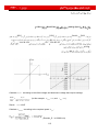
Analog-Speed
Analog-Speed
FD
FD
Kinco JD 伺服系列使用手册
Analog-Speed
Analog-Speed
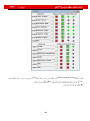
Range
Default
Display
D3.22
Analog1_Filter
Smooth
f=
T=
D3.23
Analog1_Dead
Dead Zone
D3.24
Analog1_Offset
Offset
D3.25
Analog2_Filter
Smooth
FD
Kinco JD 伺服系列使用手册
f=
T=
D3.26
Analog2_Dead
Dead Zone
D3.27
Analog2_Offset
Offset
D3.28
Analog_Speed_C
on
N/A
Analog-Speed
Invalid
0
AIN1 Valid
1
AIN2 Valid
2
10 – 17 : AIN1 For Din_Speed (X-10)
20 – 27 : AIN2 For Din_Speed (X-20)
Valid in Mode -3 . 3 and 1
D3.29
Analog_Speed_F
actor
D3.32
Analog_MaxT_C
on
D3.33
N/A
No Control
N/A
0
AIN1
1
AIN2
2
Analog_maxT_Fa
ctor
N/A
2 1 d3.28
-3 3 1
20-27 10-17 d3.28
10-17 d3.28
Din_Spee
Din_Spee
Din_Spee
Din_Spee
Din_Spee
Din_Spee
Din_Spee
Din_Spee
FD
d0
Kinco JD 伺服系列使用手册
d1
d2
d3
d4
d5
d6
d7
20-27 d3.28
Din_Spee
d0
Din_Spee
d1
Din_Spee
d2
Din_Spee
d3
Din_Spee
d4
Din_Spee
d5
2047
Din_Spee
d6
Din_Spee
d7
2047
1
-10v
2
-10v
10v
0
-2048
10v
-2048
Offset
Dead zone
Offset ADC
Dead Zone
Dead Zone
Mathematical equation for offset processing:
U int ernal U external U shift
Mathematical equation for dead zone processing:
U int ernal 0 U dead U external U dead
U external
U
U
U external U dead dead
int
ernal
U dead U external
Offset
FD
Kinco JD 伺服系列使用手册
Mathematical equation for integrated processing (offset and dead zone)
U int ernal 0 U dead U external U shift U dead
U dead U external U shift
U
U
U
U
int
ernal
external
shift
dead
U dead U external U shift
Dead
Offset
Zone
Offset
Analog_Offset0-8191
Dead Zone
Analog_Dead0-8191
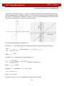
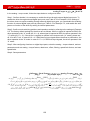
The obtained analog signal U int ernal obtains U filter after passing through a first-order low-pass filter,
and is applied by the internal programs again.
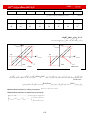
In the analog – speed mode, if the analog signal U filter that passes through the filter is multiplied by a
factor, this signal will be regarded as the internal target speed Vdemand .
Mathematical formula:
Vdemand
Vdemand Factor *U filter 2048 U filter 2047
Formula for Vrpm conversion:
Resolution
FD
Kinco JD 伺服系列使用手册
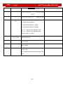
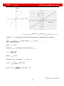
Analog-Speed
Analog-Speed
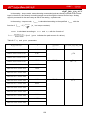
Step 1
Calculate U filter according to the offset voltage
U filter
2047
10v 10v U shift U dead
and dead zone voltage that require settings
Step 2
Calculate Vdemand according to the required speed
Vrpm
Step 3
Step 4
Vdemand Factor *U filter
Factor
Dead Zone
Step 5
8191/10v Ana log_ Dead / U dead
Analog_Dead
Offset
8191/10v Ana log_ Offset / U shift
Analog_Offset
Analog-Speed
Analog-Speed
Enable
Enable
Enable
Enable
Disable
Enable
Auto Power-On
Disable
Default
Operation
d3.17 =-3
DIN3
d3.16
Analog-Speed
Filtering Offset Dead Zone Analog- Speed
FD
Offset
DIN3
-3000 R.P.M
Dead Zone
DIN2
Kinco JD 伺服系列使用手册
Analog-Speed
Enable
DIN1
-10V 3000 R.P.M
AIN1
Calculate U filter according to the offset voltage and dead zone voltage that require settings:
U filter
2047
10v 10v U shift U dead
(In this example, U dead 0 , and U shift 0 )
Result: U filter =2047
Calculate Vdemand according to the required speed Vrpm :
(Encoder_R is 10000 inc/r)
FD
Kinco JD 伺服系列使用手册
Result: Vdemand 8192000
Calculate Factor according to U filter and Vdemand :
Vdemand Factor *U filter
Result: Factor 4000
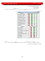
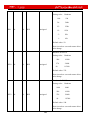
Display
D3.01
Din1_Function
000.1 (Drive Enable)
D3.02
Din2_Function
000.2 (Error Reseting)
D3.03
Din3_Function
000.4 (Control Over Operation
Modes Of Drivers)
D3.05
Din5_Function
The default value 001.0 changes
to 000.0 (position positive limits
are disabled)
D3.06
Din6_Function
The default value 002.0 changes
to 000.0 (position negative limits
are disabled)
D3.16
Din_Mode0
Operation
Invalid
D3.17
D3.22
Din_Mode1
Analog1_Filter
(instantaneous speed mode)
Operation
Set to 0.003 (3) mode
valid
(speed mode with
acceleration/deceleration)
Smooth
f=
Set to 0.003 (-3) mode
FD
Kinco JD 伺服系列使用手册
T=
D3.23
Analog1_Dead
Dead Zone
Set to 0
D3.24
Analog1_Offset
Offset
Set to 0
D3.28
Analog_Speed_C
on
Chooses analog-speed channels
Set to 1
0: Invalid analog channel
1: Valid analog channel 1 (AIN1)
2: Valid analog channel 2 (AIN2)
10~17:AIN1 for “Din_Speed (X-10)”
20~27:AIN2 for “Din_Speed (X-20)”
Valid in mode -3, 3 and 1.
D3.29
D2.10
Analog_
Speed_Factor
Set the proportion between analog signals
and output speed
Profile_Acce_16 Set the acceleration in operation mode 3
Set to 4000
610 by defaut
and 1.(rps/s)
D2.11
Profile_ Dece_16 Set the deceleration in operation mode 3
610 by defaut
and 1.(rps/s)
D3.00
Store_Loop_Data 1: Storing all configured parameters for the Set to 1
control loop
10: Initializing all parameters for the control
loop
FD
Kinco JD 伺服系列使用手册
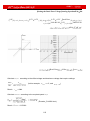
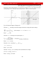
Setting the Dead Zone Voltage Analog-Speed
10V
0.5V -0.5V
0.5V -0.5V Dead Zone
-3000 R.P.M -10V
3000 R.P.M
AIN1
Dead Zone
Offset
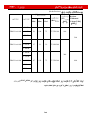
Calculate U filter according to the offset voltage and dead zone voltage that require settings:
U filter
2047
10v 10v U shift U dead
(In this example, U dead 0 .5, and U shift 0 )
Result: U filter =1944
Calculate Vdemand according to the required speed : Vrpm
, (Encoder_R:10000 inc/r)
Result: Vdemand 8192000
FD
Kinco JD 伺服系列使用手册
Calculate U filter according to Vdemand and Factor :
Vdemand Factor *U filter
Result: Factor =4213
Calculate Ana log1_ Dead according to the required dead zone voltage:
8191/10v Ana log1_ Dead / U dead
Result: Ana log1_ Dead =410
The following changes are required on the basis of Example 8-3.
D3.23
Analog1_Dead
D3.29
Analog_Speed_Factor
D3.00
Store_Loop_Data
Dead Zone
Analog1_Dead
Analog_Speed_Factor
Store_Loop_Data
FD
Kinco JD 伺服系列使用手册
Offset
Analog-Speed
Requirement: The offset voltage is 1 V, that is, the speed is positive when the voltage is greater than 1
V, and is negative when the voltage is less than 1 V. In this case, the voltage 10 V corresponds to 3000
rpm, and -9 V corresponds to -3000 rpm (in case of -10 V, the corresponding speed is less than -3000
rpm). Select analog channel 1 (AIN1) to control the speed.
Fig. 8-9 Schematic diagram of Example 8-5
Calculate U filter according to the offset voltage and dead zone voltage that require settings:
U filter
2047
10v 10v U shift U dead
Result:
(In this example, U dead 0 , and U shift 1 )
U filter 1842
Calculate Vdemand according to the required speed : Vrpm
, (Encoder_R:10000 inc/r)
Result: Vdemand 8192000
Calculate U filter according to Vdemand and Factor :
Vdemand Factor *U filter
Result: Factor =4447
Calculate Ana log1_ Offset according to the required offset voltage:
FD
Kinco JD 伺服系列使用手册
8191/10v Ana log1_ Offset / U shift
Result: Ana log1_ Offset =819
The following changes are required on the basis of Example 8-3.
D3.24
Analog1_Offset
D3.29
Analog_Speed_Factor
Set to 4447
D3.00
Store_Loop_Data
Set to 1
Offset
Set to 819
FD
Kinco JD 伺服系列使用手册
Offset
Dead Zone
Analog-Speed
Requirement: Set the offset voltage to 1V, the dead zone voltage to 0.5V to 1.5V, and the max speed
corresponding to 10V to 3000 rpm. Select analog channel 1 (AIN1) to control the speed.
Fig. 8-10 Schematic diagram of Example 8-6
Calculate U filter according to the offset voltage and dead zone voltage that require settings:
U filter
2047
10v 10v U shift U dead
(In this example, U dead 0 .5, and U shift 1 )
Result: U filter =1740
Calculate Vdemand according to the required speed : Vrpm
, (Encoder_R:10000 inc/r)
Result: Vdemand 8192000
Calculate Factor according to U filter and Vdemand :
Vdemand Factor *U filter
Result: Factor =4708
Calculate Ana log1_ Dead according to the required dead zone voltage:
8191/10v Ana log1_ Dead / U dead
Result: Ana log1_ Dead =409
FD
Kinco JD 伺服系列使用手册
Calculate Ana log1_ Offset according to the required offset voltage:
8191/10v Ana log1_ Offset / U shift
Result: Ana log1_ Offset =819
The following changes are required on the basis of Example 8-3.
Table 8-15 Parameter settings in Example 8-6
d3.23
Analog1_Dead
Sets dead zone data
for external analog
signal 1
Set to 409
d3.24
Analog1_Offset
Sets offset data for
external analog signal
1
Set to 819
d3.29
Analog_Speed_Factor
Sets the proportion
between analog
signals and output
speed
Set to 4708
d3.00
Store_Loop_Data
1: Storing all
configured parameters
for the control loop
Set to 1
10: Initializing all
parameters for the
control loop
FD
Kinco JD 伺服系列使用手册
Torque Mode
FD
Range
Default
Display
D3.22
Analog1_Filter
Smooth
f=
T=
D3.23
Analoge1_Dead
Dead Zone
FD
D3.24
Analog1_Offset
D3.25
Analog1_Filter
Kinco JD 伺服系列使用手册
Offset
Smooth
f=
T=
D3.26
Analog2_Dead
Dead Zone
D3.27
Analog2_Offset
Offset
D3.30
Analog_Torque_Con
N/A
Analoge_Torque
Invalid
AIN1 Valid
AIN2 Valid
Valid Mode 4
D3.31
Analog_Torque_Fact
or
D2.15
Speed_Limit_Factor
D2.24
Max_Speed_RPM
N/A
FD
Kinco JD 伺服系列使用手册
In the analog – torque mode, external analog command signals are directly inputted to the current
loops in the driver, thus directly controlling target current through the internal current loop. Analog
signal is processed in the same way as that in the analog – speed mode.
In the analog – torque mode, I demand is calculated according to the specified Tdemand with the
formula of Tdemand Kt *
I demand
2
( K t is a torque constant).
Factor is calculated according to I demand and U filter with the formula of
I demand
Factor *U filter
2048*2048
* Ipeak ( Ipeak indicates the peak current of a driver).
Table 8-17 K t and Ipeak parameters
SMH60S-0020-30AXK-3LKX
0.48
SMH60S-0040-30AXK-3LKX
0.48
SMH80S-0075-30AXK-3LKX
0.662
SMH80S-0100-30AXK-3LKX
0.562
SMH110D-0105-20AXK-4LKX
0.992
SMH110D-0126-20AXK-4LKX
1.058
SMH130D-0105-20AXK-4HKX
1.1578
SMH130D-0157-20AXK-4HKX
1.191
SMH110D-0126-30AXK-4HKX
1.058
SMH110D-0157-30AXK-4HKX
0.992
SMH110D-0188-30AXK-4HKX
1.058
SMH130D-0105-20AXK-4HKX
1.1578
SMH130D-0157-20AXK-4HKX
1.191
SMH130D-0210-20AXK-4HKX
1.3232
SMH150D-0230-20AXK-4HKX
1.65
FD422
FD432
FD622
FD
Kinco JD 伺服系列使用手册
Analog-Torque
Analog-Torque
Step 1
Offset
Dead Zone
Step 2
√
Step 3
Step 4
Factor
Analog_Dead
Dead Zone
Step 5
Analog_Offset
Offset
FD
Kinco JD 伺服系列使用手册
Analog-Torque
In the analog – torque mode, follow the steps below to configure a driver:
Step 1: Confirm whether it is necessary to enable the driver through external digital input ports. To
enable the driver through external digital input ports, see Table 6-12 in Example 6-3 for settings. If
the driver does not require enabling through external digital input ports, you can disable the enabling
function of external digital input ports by referring to Table 6-13 of Example 7-3, and enable the auto
power-on function of the driver by setting its internal parameters.
Step 3: Confirm mode switching positions and operation modes by referring to the settings in Example
6-5. The factory default settings for the driver are as follows: When no signal is inputted to DIN3, the
driver operates in the “-4” mode (d3.16 = -4); when signal is inputted to DIN3, the driver operates in the
“-3” mode (d3.17 = -3). If the driver is required to operate in the torque mode (“4” mode), please set
d3.16 or d3.17 to 4. In case d3.16 = 4, if DIN3 has no input signals when the driver is powered on, the
driver operates in the “4” mode. In case d3.17 = 4, if DIN3 has input signals, the driver operates in the
“4” mode.
Step 3: After configuring functions on digital input ports, select the analog – torque channel, and set
parameters such as analog – torque factors, dead zone, offset, filtering, speed limit factors, and max
speed limits.
Step 4: Save parameters.
Offset
DIN3
-10
Dead Zone
Rest
15 A
Analog-Torque
DIN2
DIN1
0.48
(AIN1)
0.64 N.m
10V
-0.64 N.m V
FD
Dead Zone
Kinco JD 伺服系列使用手册
Offset
Calculate U filter according to the offset voltage and dead zone voltage that require settings:
U filter
2047
10v 10v U shift U dead
(In this example, U dead 0 , and U shift 0 )
Result: U filter =2047
Calculate I demand according to the required torque Tdemand :
I demand
Tdemand
* 2
Kt
Result: I demand =1.89
Calculate Factor according to U filter and I demand :
Factor
I demand
*2048*4096
U filter * Ipeak
Result: Factor
1.89
*2048*4096 515
2047*15
FD
Kinco JD 伺服系列使用手册
Display
D3.01
Din1_Function
000.1 (Driver Enable)
D3.02
Din2_Function
000.2 (Error Resetting)
D3.03
Din3_Function
000.4 (Control Over
Operation Modes of
Drivers)
D3.16
Din_Mode0
Set to 0004 (4) Mode
(Torque Mode)
Operation Mode
Invalid
D3.17
Din_Mode1
Set to 000.3 (3) Mode
(Speed Mode With
Acceleration /
Deceleration)
Operation Mode
valid
D3.25
Analog2_Filter
Smooth
f=
T=
D3.26
Analog2_Dead
dead zone
Set to 0
D3.27
Analog2_Offset
offset
Set to 0
D3.31
Analog_Torque_Factor
D3.30
Analog_Torque_Con
Set to 515
Set to 2
Analog-Torque
Invalid
AIN1
Valid
0
1
FD
AIN2
D3.00
Valid
Store_Loop_Data
Kinco JD 伺服系列使用手册
2
Set to 1
Control Loop
Control Loop
FD
Kinco JD 伺服系列使用手册
Offset
Dead Zone
0.48 N.m/A
Analog-Torque
0.5V Dead Zone
0.64 N.m
10V
1V Offset
15A
Calculate U filter according to the offset voltage and dead zone voltage that require settings:
U filter
2047
10v 10v U shift U dead
(In this example, U dead 0 .5, and U shift 1 )
Result: U filter =1740
Calculate I demand according to the required torque Tdemand :
I demand
Tdemand
* 2
Kt
Result: I demand = 1.89
Calculate Factor according to U filter and I demand :
Factor
I demand
*2048*4096
U filter * Ipeak
Result: Factor
1.89
*2048*4096 606
1740*15
Calculate Ana log 2 _ Dead according to the required dead zone voltage:
FD
Analog 2 _ Dead
Kinco JD 伺服系列使用手册
8191
*U dead
10v
Result: Ana log 2 _ Dead = 410
Calculate Ana log 2 _ Offset according to the required offset voltage:
Analog 2 _ Offset
8191
*U shift
10v
Result: Ana log 2 _ Offset =819
The following changes are required on the basis of Example 8-7.
D3.26
Analog2_Dead
D3.27
Analog2_Offset
D3.31
Analog_Torque_Factor
D3.00
Store_Loop_Data
Set to 410
Dead Zone
Set to 819
Offset
Set to 2362
Control
1
Loop
Control Loop
10
Set to 1
FD
Kinco JD 伺服系列使用手册
1
Internal Multi-Position Control Modes (“1” Mode)
Internal
Internal Position Control1 Internal Position Control0
Position Control 2
2, At least one of the external input signal is defined as “Internal position control 0”, “Internal position
control 1 “ or “Internal position control 2 “, which means at least one address of digital tubes-d3.01 ~
d3.07 is set to “040.0”’, “080.0” or “800.2.
“Internal position control 0” , “Internal position control 1” and “Internal position control 2 “, these three
signals will be combined into binary codes used to select a target position between “Position 0~7”.
Internal
Position
0
Internal
Position
1
Internal
Position
2
Position Section
Numberic Display
0
0
0
Din_Pos0
0
0
1
Din_Pos1
0
1
0
Din_Pos2
0
1
1
Din_Pos3
1
0
0
Din_Pos4
1
0
1
1
0
1
0
Speed
Section
Numberic
Display
Din_Speed0_RPM
D3.18
Din_Speed1_RPM
D3.19
Din_Speed2_RPM
D3.20
Din_Speed3_RPM
D3.21
Din_Speed4_RPM
D3.44
Din_Pos5
Din_Speed5_RPM
D3.45
0
Din_Pos6
Din_Speed6_RPM
D3.46
1
Din_Pos7
Din_Speed7_RPM
D3.47
D3.40
High
D3.41
Bit
Low Bit
D3.42
Note: In this control mode, “position section X” can be positive or negative, it can be flexibly set; while
the corresponding speed must be positive. Other parameters such as acceleration, deceleration, etc,
can use the default value; also can be changed through digital tube.
FD
Kinco JD 伺服系列使用手册
100 R.P.M
0
150 R.P.M
175 R.P.M
200 R.P.M
300 R.P.M
325 R.P.M
275 R.P.M
460 R.P.M
DIN1
DIN3
Invalid 1,Valid-3
DIN4
Internal Position 0
DIN5
Internal Position 1
DIN6
Internal position 2
DIN6:DIN5:DIN4=0:0:0
DIN6:DIN5:DIN4=0:0:1
DIN6:DIN5:DIN4=0:1:0
DIN6:DIN5:DIN4=0:1:1
DIN6:DIN5:DIN4=1:0:0
DIN6:DIN5:DIN4=1:0:1
DIN6:DIN5:DIN4=1:1:0
FD
Kinco JD 伺服系列使用手册
DIN6:DIN5:DIN4=1:1:1
DIN6
Display
D3.01
Din1_Function
000.1
D3.03
Din3_Function
000.4
D3.04
Din4_Function
040.0
D3.05
Din5_Function
080.0
D3.06
Din6_Function
800.2
D3.07
Din7_Function
400.2
D3.16
Din_Mode0
Set 000.1 (1) internal
Multi-Position Control Mode
D3.17
Din_Mode1
Set 000.4 (-4) Mode
Pulse-Control Mode
D3.00
Numberic
display
1
Variable Name
Parameters Settings
d3.43
Relative / Absolute position selection
Set to 2F(absolute location)
d3.40
Set the position section number to 0
Set to 0(select position section 0
)
FD
d3.41
Set the high bit of position section(
N*10000)
d3.42
Set the low bit of position section
d3.18
Set the speed of section 0
d3.40
Set the position section number to 1
d3.41
Set the high bit of position section(
N*10000)
Kinco JD 伺服系列使用手册
Set to 0
Set to 5000(set the position of
section 0 t0 5000)
Set to 100(set the speed of
section 0 to 100)
Set to 1(select position section 1
)
Set to 1
Set to 15000(set the position of
d3.42
Set the low bit of position section
d3.19
Set the speed of position section 1
d3.40
Set the position section number to2
d3.41
Set the high bit of position section(
N*10000)
Set to 2
d3.42
Set the low bit of position section
Set to 28500(set the position of
section 2 t0 28500)
d3.20
Set the speed of position section 1
Set to 175(set the speed of
section 2 to 175)
d3.40
Set the position section number to 3
Set to 3(select position section 3
)
d3.41
Set the high bit of position section(
N*10000)
section 1 t0 15000))
Set to 150(set the speed of
section 1 to 150)
Set to 2(select position section 2
)
Set to 3
d3.42
Set the low bit of position section
Set to 10500(set the position of
section 3 t0 10500)
d3.20
Set the speed of position section 3
Set to 200(set the speed of
section 3 to 200)
d2.10
Acceleration
Default 610 rps/s
d2.11
Deceleration
Default 610 rps/s
FD
Kinco JD 伺服系列使用手册
d3.00
Storage parameter
1(storage configuration
parameters)
Set all these parameters, then:
1. Enable the driver, which means to make the digital input DIN1 high-level.
2. Select the position section, which means to change the electrical level of DIN4,DIN5 and DIN6.
3. Activate instructions and execute the program, which means to make the digital input DIN7
high-level.
Notice:
In multi-position control mode, select location method by setting the different value of the digital tube
d3.43.If you choose absolute positioning mode, set it to “F”; if the instructions require immediate
updating, set it to “2F”; if you choose relative positioning method, set it to “4F”.To change these
parameters successfully, you have to save the value of d3.00,and then restart.
FD
Kinco JD 伺服系列使用手册
Internal Multi-Speed Control Modes (-3 or 3 Mode)
Analoge-Speed
0
Bit9 Bit8
020.0
Din3
D3.28
DinX
Din3 010.0
Din2
Din2
Din_Speed2_RPM Din_Speed1_RPM Din_Speed0_RPM
Din_Speed3_RPM
Internal Speed
Control 0
(Din_Sys.Bit8)
Internal Speed
Control
(Din_Sys.Bit9)
0
0
1
Valid Object
Display
Display
(Numeric
Operation)
Multi-Speed Control : 0 RPM
D3.18
Din_Speed0_RPM
0
Multi-Speed Control : 1 RPM
D3.19
Din_Speed1_RPM
0
1
Multi-Speed Control : 2 RPM
D3.20
Din_Speed2_RPM
1
1
Multi-Speed Control : 3 RPM
D3.21
Din_Speed3_RPM
Din_Speed1 Din_Speed0
Four Data
RPM
Din_SpeedX
Host Computer
Din_SpeedX_RPM
Din_Speed3 Din_Speed2
FD
Kinco JD 伺服系列使用手册
DIN1
DIN7 DIN6
Operation
DIN2
(the mode is “3” when the driver is valid, and is “-3” when the driver is invalid). For detailed
requirements, see Table 8-25. For the setting method, see Table 7-26.
DIN6 : DIN7=0:0
100 RPM
1 (Multi-Step)
DIN6 : DIN7=1:0
200 RPM
2(Multi-Step)
DIN6 : DIN7=0:1
300 RPM
3(Multi-Step)
DIN6 : DIN7=1:0
400 RPM
4(Multi-Step)
DIN1
Enable
DIN2
Control Operation
Invalid
Valid
Display
D3.01
Din1_Function
Set to 000.1
(Driver Enable)
D3.02
Din2_Function
Set to 000.4
(Control Over Operation Modes of
Drivers)
D3.06
Din6_Function
Set to 010.0
(Internal Speed Control 0)
FD
D3.07
Din7_Function
Kinco JD 伺服系列使用手册
Set to 020.0
(Internal Speed Control 1)
D3.16
Din_Mode0
Set to 0.003 (3) Mode
D3.17
Din_Mode1
Set to 0.003 (-3) Mode
D3.18
Din_Speed0_RPM
Set to 100 rpm
D3.19
Din_Speed1_RPM
Set to 200 rpm
D3.20
Din_Speed2_RPM
Set to 300 rpm
D3.21
Din_Speed3_RPM
Set to 400 rpm
D3.00
Store_Loop_Data
FD
Kinco JD 伺服系列使用手册
Internal Torque Control Mode
d3.30
d0.03
In the internal torque mode, only the current loop of the driver operates. Set d0.03 (CMD_q target
current) parameter directly to obtain the desired target torque. The prerequisite is that d3.30 must be
set to 0. In this case, the analog–torque channel is invalid.
„6‟ Mode
X.Y 100mm, 200mm
Homing Mode
XY Plane
FD
Kinco JD 伺服系列使用手册
Homing
Homing
I/O
Homing
Homing
Homing
Homing
0x607C0020 Home_Offset
Home offset
In Homing mode, set the offset
relative to the zero point.
0x60980008
Homing_Method
Homing method
Select the homing method
0x60990120
Homing_Speed_Switch Speed for searching
the limit switch
Set the speed for searching the limit
switch which defined as homing
signal.
0x60990220
Homing_Speed_Zero
Speed for searching
the Zero point.
Only valid when find Index signal.
0x60990308
Homing_Power_On
Homing when power
on
Every time after power on,it will start
homing once.
0x609A0020
Homing_Accelaration
Homing acceleration
Control the acceleration of homing
DSP402 CANOPEN
Homing
Homing Signal Z Signal
Homing Signal External Signal
FD
FD
Kinco JD 伺服系列使用手册
Method 1: Homing on the negative limit switch and index pulse
Using this method, the initial direction of movement is leftward if the negative limit
switch is inactive (here shown as low). The home position is at the first index pulse to the
right of the position where the negative limit switch becomes inactive.
Method 2: Homing on the positive limit switch and index pulse
Using this method, the initial direction of movement is rightward if the positive limit
switch is inactive (here shown as low). The position of home is at the first index pulse to
the left of the position where the positive limit switch becomes inactive.
Methods 3 and 4: Homing on the positive home switch and index pulse
Using methods 3 or 4, the initial direction of movement is dependent on the state of the
home switch. The home position is at the index pulse to either the left or right of the pint
where the home switch changes state. If the initial position is sited so that the direction of
FD
Kinco JD 伺服系列使用手册
movement must reverse during homing, the point at which the reversal takes place is
anywhere after a change of state of the home switch.
Methods 5 and 6: Homing on the negative home switch and index pulse
Using methods 5 or 6, the initial direction of movement is dependent on the state of the
home switch. The home position is at the index pulse to either the left or the right of the
point where the home switch changes state. If the initial position is sited so that the
direction of movement must reverse during homing, the point at which the reversal takes
place is anywhere after a change of state of the home switch.
FD
Kinco JD 伺服系列使用手册
Methods 7 to 14: Homing on the home switch and index pulse
These methods use a home switch that is active over only a portion of the travel; in effect
the switch has a “momentary” action as the axle position sweeps past the switch.
Using methods 7 to 10, the initial direction of movement is to the right, and using
methods 11 to 14, the initial direction of movement is to the left, except if the home
switch is active at the start of motion. In this case, the initial direction of motion is
dependent on the edge being sought. The home position is at the index pulse on either
side of the rising or falling edges of the home switch, as shown in the following two
diagrams. If the initial direction of movement leads away from the home switch, the
drive must reverse on encountering the relevant limit switch.
FD
Kinco JD 伺服系列使用手册
Methods 15 and 16: Reserved
These methods are reserved for future expansion of the homing mode.
Methods 17 to 30: Homing without an index pulse
These methods are similar to methods 1 to 14, except that the home position is not
FD
Kinco JD 伺服系列使用手册
dependent on the index pulse; it is dependent only on the relevant home or limit switch
transitions. For example, methods 19 and 20 are similar to methods 3 and 4, as shown in
the following diagram:
FD
Kinco JD 伺服系列使用手册
FD
Methods 31 and 32: Reserved
These methods are reserved for future expansion of the homing mode.
Methods 33 and 34: Homing on the index
Method 35: Homing on the current position
In this method, the current position is taken to be the home position.
Methods -17 and -18: Use the mechanical terminal as reference point
Kinco JD 伺服系列使用手册
FD
Kinco JD 伺服系列使用手册
Homing
Display
D3.01
D3.02
D3.03
D3.04
D3.05
D3.06
D3.07
D3.14
D3.15
Din1_Functi
on
000.1 : Driver Enabled
000.2 : Driver Error Rest
Din2_Functi
on
Din3_Functi
on
Din4_Functi
on
Din5_Functi
on
Din6_Functi
on
Din7_Functi
on
Dout4_Funct
ion
Dout4_Funct
000.4 : Operation Mode
001.0 : Positive Limit
002.0 : Negative Limit
004.0 : Origin Signal
000.1 (Driver
Enabled)
000.2 (Driver Error
Rest)
000.4 (Driver Model
Control)
200.0 (Start Homing)
001.0 (Positive Limit)
200.0 : Start Homing
002.0 (Negative
Limit)
004.0 (Home Signal)
004.0 : Index Signal Appears
040.0 : Origin Found
004.0 (Index Signal
Appears)
040.4 (Origin Found)
ion
D3.16
Din_Mode0
D3.17
Din_Mode1
D3.00
Store_Loop_
Data
Invalid
Valid
0.004(-4)
0.003(-3)
0001(1)
FD
P.L
Kinco JD 伺服系列使用手册
Normally Close
Origin
Default
No Limit
N.L Positive Limit
Control
FD
Kinco JD 伺服系列使用手册
Homing
In common circumstance, only need to set up the model of origin and the rest of the parameters are
default. In some case, “Electrify and then find the origin” is set to 1, at the same time the definition-“Start finding the origin” is eliminated.
FD
Kinco JD 伺服系列使用手册
Start Homing
High Level
High Level
Enable Motor
Start Finding the Origin
FD
Rise
Kinco JD 伺服系列使用手册
Start Finding the Origin
Rise
On
FD
Kinco JD 伺服系列使用手册
Origin
Z
FD
Default
Kinco JD 伺服系列使用手册
Origin Search
FD
Kinco JD 伺服系列使用手册
FD
Kinco JD 伺服系列使用手册
Auto Reverse
Auto Reverse
kinco Servo
Auto Reverse
Auto_Rev_Neg Auto_Rev_Pos
Auto_Rev_Neg Auto_Rev_Pos
Driver Operation Mode-Auto Reverse
1
Auto Reverse
Auto_Reverse
ms
100 RPM
10000 -10000 inc
FD
Kinco JD 伺服系列使用手册
Default
FD
Kinco JD 伺服系列使用手册
Rang
e
Display
Default
D2.01
Kvp
D2.02
Kvi
D2.05
Speed-F
b_N
Smooth
F = Speed_Fb_N
F=500 Hz
20 + 100
Kvp
Kvi
Adjustment steps:
Step 1: Adjust the gain of velocity loop to calculate the bandwidth of velocity loop
FD
Kinco JD 伺服系列使用手册
Convert the load inertia of the motor into the inertia Jl of the motor shaft, and then add the inertia Jr of
the motor itself to obtain Jt = Jr + Jl. Put the result into the formula:
Vc_Loop_BW Kvp *
I p * Kt * Encoder _ R
J t * 204800000* 2 * 2
To calculate the bandwidth of the velocity loop
Vc_Loop_BW according to the adjusted the gain of velocity loop Kvp, only adjust Kvi according to
actual requirements.
Adjust the impact of Kvp and Kvi, as shown in Fig.9-2.
For the effect of Kvp adjustment, see the first to the fourth from left of Fig. 9-2. Kvp gradually increases
from the first to the fourth from left. The value of Kvi is 0.
For the effect of Kvi adjustment, see the first to the fourth from right of Fig. 9-2. Kvi gradually increases
from the first to the fourth from right. The value of Kvp remains unchanged.
Left 1
Left 2
Right 1
Right 2
FD
Left 3
Left 4
Kinco JD 伺服系列使用手册
Right 3
Right 4
Step 2: Adjust parameters for feedback filter of velocity loop
During gain adjustment of a velocity loop, if the motor noise is too great, you can properly reduce the
parameter Speed_Fb_N for feedback filter of the velocity loop; however, the bandwidth F of the
feedback filter of velocity loop must be at least three times of the bandwidth of velocity loop; otherwise
oscillation may occur. The formula for calculating the bandwidth of feedback filter of velocity loop is F
= Speed_Fb_N*20+100 (Hz).
FD
Kinco JD 伺服系列使用手册
Default
Range
Display
d2.07
Kpp
1000
0~16384
d2.08
K_Velocity_FF
256
0~256
d2.09
K_Acc_FF
7FF.F
32767~10
d0.05
Pc_Loop_BW
0
N/A
/
Pos_Filter_N
1
1~255
Kpp
Hz
Average
Proportional gain of the position loop Kpp: If the proportional gain of the position loop increases, the
bandwidth of the position loop is improved, thus reducing both the positioning time and following
errors. However, too great bandwidth may cause noise or even oscillation. Therefore, this parameter
must be set properly according to loading conditions. In the formula Kpp=103* Pc_Loop_BW,
Pc_Loop_BW indicates the bandwidth of the position loop. The bandwidth of a position loop is less
than or equal to that of a velocity loop. It is recommended that Pc_Loop_BW be less than
Vc_Loop_BW /4 (Vc_Loop_BW indicates the bandwidth of a velocity loop).
Velocity feedforward of the position loop K_Velocity_FF: the velocity feedforward of a position loop
can be increased to reduce position following errors. When position signals are not smooth, if the
velocity feedforward of a position loop is reduced, motor oscillation during running can be reduced.
Acceleration feedback of the position loop K_Acc_FF (adjustment is not recommended for this
parameter): If great gains of position rings are required, the acceleration feedback K_Acc_FF can be
properly adjusted to improve performance. K_Acc_FF
I p * Kt * Encoder _ R
250000* 2 * J t *
Note: K_Acc_FF is
inversely proportional to the acceleration feedforward.
Pos_Filter_N is used for average filter of the speed produced by target position.Setting this parameter
as N means to average N data.
FD
Kinco JD 伺服系列使用手册
Adjustment procedure:
Step 1: Adjust the proportional gain of a position loop.
After adjusting the bandwidth of the velocity loop, it is recommended to adjust Kpp according to actual
requirements (or directly fill in the required bandwidth in Pc_Loop_BW, and the driver will
automatically calculate the corresponding Kpp). In the formula Kpp = 103*Pc_Loop_BW, the
bandwidth of the position loop is less than or equal to that of the velocity loop. For a common system,
Pc_Loop_BW is less than Vc_Loop_BW /2; for the CNC system, it is recommended that Pc_Loop_BW
is less than Vc_Loop_BW /4.
Step 2: Adjust velocity feedforward parameters of the position loop.
Velocity feedforward parameters (such as K_Velocity_FF) of the position loop are adjusted according
to position errors and coupling intensities accepted by the machine. The number 0 represents 0%
feedforward, and 256 represents 100% feedforward.
3. Parameters for pulse filtering coefficient
Kpp
Numeric Display
Range
Default
d3.37
PD_Filter
Smooth
: f = 1000/(2π* PD_Filter)
: T = PD_Filter/1000
3
1~32767
FD
Kinco JD 伺服系列使用手册
:S
High
Motor Oscillation
Kvi Kvp
K_Load
K _ Load
I p * Kt * Encoder _ R
62500* 2 * J t
FD
Kinco JD 伺服系列使用手册
A
Nm/Arms
inc/r
Resolution
kg*m^2
Loading
Auto Tuning
Range
Default
Display
d0.06
Tuning_Start
Auto tuning starts after the variable is set to 11.
All input signals are ignored during auto tuning.
The variable is automatically changed to 0 after
auto tuning is completed.
0
/
0
0~600
/
20~1500
0
64
0~1000
128
0~16384
Sets the variable to other values to end auto
tuning.
d0.04
Vc_Loop_BW
Sets the bandwidth of the velocity loop in
Hz.The variable can only be set after auto tuning
is performed properly; otherwise the actual
bandwidth goes wrong, which causes abnormal
working of the driver.If the auto tuning result is
abnormal, setting this parameter may also cause
abnormal working of the driver.
Note: This parameter cannot be applied when
auto tuning is unavailable.
d2.17
K_Load
d2.21
Sine_Amplitude
d2.22
Tuning_Scale
Loding
Proper increase in this data will reduce the
tuning error, but machine vibration will become
severer. This data can be adjusted properly
according to actual conditions of machines. If
the data is too small, the auto tuning error
becomes greater, or even causes a mistake
Auto tuning
FD
d2.23
Kinco JD 伺服系列使用手册
Tuning_Filter
auto-tuning
64
1~1000
Auto tuning is a process where the suitable and stable K_Load value is automatically calculated. In
the auto tuning mode, the data of numeric display is automatically switched to the real-time display
mode of K_Load data. When K_Load data gradually becomes stable, the driver automatically adjusts
Kvp and Kvi data of a velocity loop, so that the actual bandwidth of the velocity loop is 50Hz. When
K_Load data becomes stable, the driver automatically stops auto tuning operation; then you need to
customize Vc_Loop_BW, representing the desired bandwidth of the velocity ring. Finally, run the test
system in the actual environment, and save the parameters.
Precautions:
Auto tuning applies when both forward rotation and reverse rotation of a motor are allowable, and the
loadings do not change much during the operation. When forward rotation or reverse rotation of the
motor is not allowable on a device, it is recommended to adjust the parameters manually.
During auto tuning operation, pulse signals, digital input signals, and analog signals of the external
controller are temporarily unavailable, so safety must be ensured.
Before auto tuning operation, it is recommended to properly adjust the Kvp, Kvi and Speed_Fb_N (a
feedback filter parameter) values of the velocity loop to prevent visible oscillations when the system
works in the speed mode. If necessary, adjust the data of d2.03 notch filter to inhibit resonance.
The time for different load tuning varies, and generally a few seconds is required. The auto tuning time
can be reduced by presetting the K_Load value to a predicted value that is close to the actual value.
Vc_Loop_BW can be written only after successful auto tuning, otherwise the driver may work
improperly. After you write the desired bandwidth of the velocity loop in Vc_Loop_BW, the driver
automatically calculates the corresponding values of Kvp, Kvi and Speed_Fb_N. If you are dissatisfied
with low-speed smoothness, you can manually adjust Kvi. Note that auto tuning does not
automatically adjust the data of a notch filter.
In the following circumstances, auto tuning parameters should be adjusted:
When the friction in a rotation circle of the motor is uneven, it is required to increase the amplitude of
d2.21 sine wave to reduce the impacts caused by uneven friction. Note that d2.21 increases when the
oscillation amplitude of the loadings increase.
If auto tuning lasts for a long time, initial evaluation of the total inertia is available. It is recommended to
set K_Load to an evaluation value before auto tuning.
If auto tuning is unstable, the stability of auto tuning increases when d2.22 increases properly, but the
time for auto tuning slightly increases.
In the following conditions, auto adjustment goes wrong. In this case, you can only set parameters
manually:
The load inertia is featured by great fluctuation.
FD
Kinco JD 伺服系列使用手册
Mechanical connection rigidity is low.
Clearances exist in the connection between mechanical elements.
The load inertia is too great, while Kvp values are set too low.
If the load inertia is too great, K_Load data will be less than 20; if the load inertia is too little, K_Load
data will be greater than 15000.
FD
Kinco JD 伺服系列使用手册
Oscillation Inhibition
notch
(BW-100)/10 Notch_N
notch
1 Notch_On
d2.14
Notch_N
Waveform
Default
Range
45
0~90
0
/
Display
d2.03
Notch_N
Notch/filtering frequency setting for a
velocity loop, used to set the frequency of the
internal notch filter, so as to eliminate the
mechanical resonance produced when the
motor drives the machine. The formula is F =
Notch_N*10 + 100.
For example, if the mechanical resonance
frequency is F = 500 Hz, the parameter
should be set to 40.
d2.04
Notch_On
Notch
notch
notch
0
1
FD
Kinco JD 伺服系列使用手册
FD
Kinco JD 伺服系列使用手册
FD
Kinco JD 伺服系列使用手册
Kvp
Auto Revarse
Kvp
Kvp
Kvi
Kvp
Speed_Fb_N
Speed_Fb_N
Kvp=40 Auto Reverse
33.88 ms
FD
Kinco JD 伺服系列使用手册
Kvp=110 Auto Reverse
FD
Kinco JD 伺服系列使用手册
10.00 ms
Kpp
K_Velocity_ff Vff
Vff
Vff
Observe
Auto Reserve
Kpp
Kpp
Vff
Vff
Kpp
FD
Kinco JD 伺服系列使用手册
50000 inc
Vff=100% Kpp=1
69 inc
FD
Vff=100% Kpp=30
Kinco JD 伺服系列使用手册
FD
Kinco JD 伺服系列使用手册
53 inc
Vff=50% Kpp=30
FD
230 inc
Kinco JD 伺服系列使用手册
FD
Kinco JD 伺服系列使用手册
FD
RS485 RS232
CANOPEN
DIN3
Enable
DIN
RS485 RS232 CANOPEN SDO Read/Write
DIN1
Default.
FD
Kinco JD 伺服系列使用手册
RS232
RS232
FD
PC
PC
FD Servo RS232(X3)
2 RxD
----------------------------------
TXD 2
3 TxD
----------------------------------
RXD 3
5 GND
---------------------------------
GND 5
DO5.15
FD
PC
Restart
HMI FD
FD
FD
FD
Kinco JD 伺服系列使用手册
RS232
LED Display
Default
Store_Loop_Data
d5.00
2FF00108
0
Station No. of Drivers
d5.01
100B0008
ID_Com
Note: To change this parameter, you
need to save it with the address
“d5.00”, and restart it later.
RS232
d5.02
2FE00010
RS232_Bandrate
Baud rate
540
19200
270
38400
90
Restart
1
270
115200
“d5.00”,
0:1:1
1:1:N
d5.15
65100B08
RS232_Loop_Enab
le
Note:It needs to restart driver after
changing
0
this parameter.
Data bit = 8
Other parameters
Stop bit = 1
Parity = None
Constant
FD
Kinco JD 伺服系列使用手册
Transport Protocol
FD
Master/Slave
FD
RS232C
ID
RS232 Transport Protocol
byte 0
ID
byte 9
8 byte data
CHKS
ID is the ID No. of the slave
CHKS = - SUM(byte0,…,byte8), CHKS is the lowest byte of the calculation result.
The host sends:
byte 0
ID
byte 9
8 byte host data
CHKS
When D5.15 is 0,FD Servo sends:
byte 0
ID
byte 9
8 byte slave data
CHKS
When D5.15 is 1,FD Servo sends:
byte 0
ID
byte 9
8 byte host data
CHKS
byte 0
ID
byte 9
8 byte slave data
CHKS
Note: Each 10-byte packet has its own CHKS.
If the host sends an ID not existed in the network to the FD Servo driver, no FD Servo driver will make
a reply. After the host sends the data correctly, the slave will find the data packets in compliance with
its own ID and check the CHKS value. If the checksum does not match, the slave will not make a
response.
FD
Kinco JD 伺服系列使用手册
RS232
Subindex Index
Transport
CANopen
Error
CD
A
A data protocol is different from a transport protocol. It contains 8 bytes of all 10 bytes of the above
RS-232. Definition of CD servo driver internal data complies with the CANopen international standard.
All parameters, values and functions are expressed by index and subindex.
A:Download. the host sends a command to write values into the objects in the slave, and the host
generates an error message when the value is downloaded to a non-existent object.
The host sends:
CMD
Specifies the direction of data transfer and the volume of data.
23(0x16)
Sends 4-byte data (bytes 4...7 contain 32 bits)
2b(0x16)
Sends 2-byte data (bytes 4, 5 contain 16 bits)
2f(0x16)
Sends 1-byte data (bytes 4 contains 8 bits)
INDEX
Index in the object dictionary where data should be sent
SUB INDEX
Subindex in object dictionary where data should be sent
In all four bytes in data, the lower-order bits are arranged before the higher-order bits. To write 7650
inc into
“Target Position” in the slave, the unit of 607A0029 is inc, 7650 is in decimal system, and 1DE2 is in
hexadecimal system.Since the length of the object to be written is 4 bytes and the calculation result 1D
E2 has only 2 bytes,zero shall be filled to the higher-order bits. Therefore, the final result = 00 00 1D
E2.
DATA: byte4=E2
byte5=1D
FD
Kinco JD 伺服系列使用手册
byte6=00
byte7=00
Slave responds:
RES:
Displays slave response:
60(0x16)
Data successfully sent
80(0x16)
Error, bytes 4…7 contain error cause
INDEX
16-bit value, same as that sent by the master
SUBINDEX 8-bit value, same as that sent by the master
RES
Reserved
For example:
Host sends:
01 23 7A 60 00 E2 1D 00 00 03 (This command is to write data into target position 607A0020)
Slave responds:
01 60 7A 60 00 E2 1D 00 00 C6
Means:
01-Station No. of slave is 1
60-Data successfully sent.And data are saved in byte4…byte5.
byte4=E2,byte5=1D,byte6=00,byte7=00
Then,DATA= byte7 byte6 byte5 byte4 = 1DE2(hex)=7650 inc
B:Upload. Upload refers to that the master sends a command to read object address in the slave and
the master will generate an error if a non-existent target address is uploaded.
The host sends:
FD
Kinco JD 伺服系列使用手册
CMD
Specifies the direction of data transfer
40(0x16)
INDEX
16-bit value
SUBINDEX 8-bit subindex
RESERVED Bytes 4…7 not used
The slave responds:
RES
Displays slave response:
43(0x16)
bytes 4...7 contain 32-bit data
4B(0x16)
bytes 4, 5 contain 16-bit data
4F(0x16)
byte 4 contains 8-bit data
80(0x16)
error, bytes 4…7 contain error cause
INDEX
16-bit value, same as that sent by the master
SUBINDEX 8-bit value, same as that sent by the maste
If the data contains no error, byte 4…byte 7 save the object value read from the slave, with the
lower-order
bits arranged before the higher-order bits. Correct value = byte7, byte6, byte5, byte4. If there is an
error, data
contained in these four types is no longer object values read from the slave.
For example:
Host sends:
01 40 7A 60 00 00 00 00 00 E5 (This command is to read data of target position 607A0020)
Slave responds
FD
Kinco JD 伺服系列使用手册
01 43 7A 60 00 E2 1D 00 00 E3
Means:
01-Station No. of slave is 1
43-Receive 4 bytes of data and save into byte4…byte5.
byte4=E2,byte5=1D,byte6=00,byte7=00
Then DATA= byte7 byte6 byte5 byte4 = 1DE2(hex)=7650 inc
RS232
Operation
Object List
RS232
FD
Kinco JD 伺服系列使用手册
RS485
RS485
RS422 RS485
FD
X2
RS485
LED
Display
Default
Station No. of Drivers
d5.01
ID_Com
Note: To change this parameter,
you need to save it with the
address “d5.00”, and restart it
later.
1
Set the baud rate of RS485 port
RS485_Bandrate
540
Note: This parameter must be
changed in KincoServo software.
Data bit = 8
Other parameters
Stop bit = 1
Parity = None
Constant
FD
Kinco JD 伺服系列使用手册
RTU
MODBUS RTU
MODBUS RTU
FD
RS485
The RS485 interface of FD Servo driver supports Modbus RTU protocol.
Modbus RTU protocol format
Start(No less than
3.5 characters of
messages interval)
Station
No.
Function
code
Data
CRC
1 Byte
1 Byte
N Bytes
2 Bytes
Function code of Modbus
0x03:Read data registers
Request format:
High Byte
Function
of Start
Code
Address
Station
No.
Low Byte
of Start
Address
High byte of
Address
Length
(Word)
1 Byte
03
1 Byte
1 Byte
1 Byte
Low byte
of
Address
Length
CRC
check
(Word)
1 Byte
2 Bytes
Normal response format:
Station
No.
Function
Code
Return data
length(Bytes)
High byte of
Register 1
Low byte of
Register 1
…
CRC
check
1 Byte
03
1 Byte
1 Byte
1 Byte
…
2 Bytes
If there is error such as non-exist address,then it will return function code 0x81.
For example:Send message 01 03 32 00 00 02 CA B3
Meaning:
01:
Station NO.
03:
Function code:read data registers
32 00:Read address starting from 4x3200(Hex).This is the modbus address corresponding to
parameter“Status word”(60410010)
00 02:Read 2 words of data
FD
Kinco JD 伺服系列使用手册
CA B3:CRC check.
0x06:Write single data register
Request format:
Station
No.
Functi
on
Code
High Byte
of Register
Low Byte
of Register
High byte
of writing
value
Low byte of
writing
CRC check
value
1 Byte
06
1 Byte
1 Byte
1 Byte
1 Byte
1 Bytes
Response format:If writing successful,then return the same message.
If there is error such as address over range,non-exist address and the address is read only,then it will
return function code 0x86.
For example:Send message 01 06 31 00 00 0F C7 32
Meaning:
01:
Station No.
06:
Function code,write single WORD
31 00: Modbus address for writing data.This is the address corresponding to parameter “control
word”(60400010)
00 0F: Write data 000F(Hex)
C7 32: CRC check.
0x10:Write multiple registers
Request format:
Station
No.
1 Byte
Function
Code
10
High
Byte of
Start
Address
1 Byte
Low
Byte of
Start
Addres
s
1 Byte
High
byte of
Addres
s
Length
Low
byte of
Addres
s
Length
(Word)
(Word)
1 Byte
1 Byte
Data
length
(Bytes
)
High
byte of
Data 1
Low
byte of
Data 1
1 Byte
1 Byte
1 Byte
…
CRC
check
… 2
Bytes
FD
Kinco JD 伺服系列使用手册
Normal respons format:
Station
No.
Function
Code
High Byte of
Start
Address
Low Byte
of Start
Address
High byte
of
Address
Length
(Word)
(Word)
1 Byte
10
1 Byte
1 Byte
Low byte
of Address CRC
Length
check
1 Byte
1 Byte
2 Bytes
If there is error such as address over range,non-exist address and the address is read only,then it will
return function code 0x90
For example:Send message 01 10 6F 00 00 02 04 55 55 00 08 1A 47
Meaning:
01:
Station No.
10:
Function code,write multiple WORDs
6F 00:
Modbus address for writing data. This is the address corresponding to parameter
“Target Velocity”(60FF0020)
00 02:
Address length is 2 WORD.
04:
Data length is 4 Bytes(2 words)
55 55 00 08:Write data 00085555(Hex) into address.
1A 47:
CRC check
RS485
Object list
RS485
FD
Kinco JD 伺服系列使用手册
CANopen
Open Fieldbus
CANopen
CaninAutomation CiA
CANopen
CiA
CAN
EN-50325-4
CANopen
CANopen
RW
RO
WO
M
S
CAN
CAN_L
CAN_H
0
CAN_L=1.5V CAN_H=3.5V
CAN
FD
Kinco JD 伺服系列使用手册
Pin
1
NC
Reserved
2
CAN_L
CAN_L bus (low dominant )
3
CAN_GND
CAN ground
4
NC
Reserved
5
CAN_SHLD
Optional shield for CAN
6
GND
Optional ground
7
CAN_H
CAN_H bus(high dominant )
8
NC
Reserved
9
CAN_V+
NC
Slave CAN_H CAN_L
Slave
Master
120Ω
CAN
24VDC
FD
Pin.3
High Baudrate
Baudrate
Baudrate
1Mbit/s
800Kbit/s
500Kbit/s
250Kbit/s
125Kbit/s
50Kbit/s
25Kbit/s
10Kbit/s
Distance
25M
50M
100M
250M
500M
600M
800M
1000M
FD
Kinco JD 伺服系列使用手册
EDS
401
Slave
Slave
Electronic Data Sheet EDS
Slave
Profibus
GSD
402
OD
403 402
Mappable OD Supportable Baudrate
Master
EDS
SDO
SDO
PID
Master
Slave
Modbus
. . . PDO
Slave
OD
SDO
SDO
PDO
PDO
PDO
PDO can transport 8 bytes of data at one time,and no other protocol preset(Mean the content of
the data are preset),it is mainly used to transmit data in high frequency.PDO uses brand new mode for
data exchange,it needs to define the data receiving and sending area before the transmission
between two devices,then the data will transmit to the receiving area of devices directly when
exchanging data.It greatly increase the efficiency and ultilization of the bus communication.
PDO COB-ID
COB-ID is a unique way of CANopen communication protocol,it is the short name
FD
Kinco JD 伺服系列使用手册
of Communication Object Identifier. These COB-ID defines the respective transmission levels for
PDO, These transport level, the controller and servo will be able to be configured the same
transmission level and the transmission content in the respective software.Then both sides know the
contents of data to be transferred, there is no need to wait for the reply to check whether the data
transmission is successful or not when transfering data.
The default ID allocation table is based on the CAN-ID(11 bits) defined in CANopen 2.0A(The COB-ID
of CANopen 2.0B protocol is 27 bits),include function code(4 bits) and Node-ID(7 bits) as shown in
following figure:
Node-ID is defined by system integrators,such setting by the DIP switch on the devices(Like servo’s
station
No.).The range of Node-ID is 1~127(0 is forbidden).
Function Code:The function code for data transmission define the transmission level of PDO,SDO and
management message.The smaller the function code,the higher the priority.
The allocation table for CAN identifiers in master/slave connection set predefined by CANopen is as
follows:
Broadcast objects
COB-ID
Index of
communication
parameter in
OD
-
Function code
Object
(ID-bits 10-7)
NMT Module
Control
0000
000H
SYNC
0001
080H
TIME SSTAMP
0010
100H
1012H,1013H
COB-ID
Index of
communication
parameter in
OD
1005H,1006H
,1007H
Reciprocity objects.
Function code
Object
(ID-bits 10-7)
FD
Kinco JD 伺服系列使用手册
Emergency
0001
081H-0FFH
1024H,1015H
PDO1(Send)
0011
181H-1FFH
1800H
PDO1(Receive)
0100
201H-27FH
1400H
PDO2(Send)
0101
281H-2FFH
1801H
PDO2(Receive)
0110
301H-37FH
1401H
PDO3(Send)
0111
381H-3FFH
1802H
PDO3(Receive)
1000
401H-47FH
1402H
PDO4(Send)
1001
481H-4FFH
1803H
PDO4(Receive)
1010
501H-57FH
1403H
SDO(Send/Server)
1011
581H-5FFH
1200H
SDO(Receive/Client
)
1100
601H-67FH
1200H
NMT Error Control
1110
701H-77FH
1016H-1017H
Note:
1. The smaller the COB-ID,the higher the priority.
2. The function codes of COB-ID in every level are fixed.
3. COB-ID of 00H, 80H, 100H, 701H-77FH, 081H-0FFH are system management format.
The COB-ID supported by FD Servo:
Send PDO(TXPDO)
Send PDO of servo means servo sends out data,and these data are received by PLC.The function
codes
of send PDO (COB-ID) are as follows:
1、 0x180+Station No. of Servo
2、 0x280+ Station No. of Servo
3、 0x380+ Station No. of Servo
4、 0x480+ Station No. of Servo
Receive PDO(RXPDO)
Receive PDO of servo means servo receive data,and these data are sent by PLC.The function codes
of receive PDO(COB-ID) are as follows:
FD
Kinco JD 伺服系列使用手册
1、 0x200+ Station No. of Servo
2、 0x300+ Station No. of Servo
3、 0x400+ Station No. of Servo
4、 0x500+ Station No. of Servo
FD Servo is designed according to the standard of CANopen 2.0A protocol,and it also supports
CANopen 2.0B protocol.Therefore,if 8 PDOs are not enough,users can define new PDO,for
example,set 0x43FH as the communication PDO of Station No.1,but it needs the controllers and servo
define PDO by the same rule.
PDO transmission types:
PDO supports two transmission mode:
SYNC: Transmission is triggered by the synchronization message(Transmission type:0-240)
In this transmission mode, controller must have the ability to send synchronous messages(The
message is sent periodically at a maximum frequency of 1KHz),and servo will send after receiving the
synchronous message.
Acyclic:Pre-triggered by remote frame,or by specific event of objects speicficed by the equipment
sub-protocol.In this mode,servo will send out data as soon as receiving the data of synchronous
message PDO.
Cyclic:Triggered after sending 1 to 240 SYNC messages.In this mode,servo will send out data in PDO
after
receiving n SYNC messages.
ASYNC(Transmission Type:254/255):
Slave sends out message automatically as soon as the data change,and it can define an interval time
between two messages which can advoid the one in high priority always sending message.(The
smaller number of PDO,the higher its priority)
PDO Inhibit Time:
Each PDO can define an inhibit time,that is the minimum interval time between two continuous PDO
transmission.It is used to advoid the PDO in higher priority always occupying the communication.The
inhibit time is 16bit unsigned integer,its unit is 100us.
Protection mode(Supervision type)
Supervision type is to choose which way master uses to check slave during operation,and check
whether slave is error or not and handle the error.
FD
Kinco JD 伺服系列使用手册
Heartbeat message:Slave send message to master cyclically during supervision time.If master hasn’t
received the message from slave after heartbeat time,then master will consider slave as error.
Message format
(0x700+NodeID)+Status
Status:
0:Start 4:Stop 5:Run 127:Pre-operational
Node Guarding: Slave send message to master cyclically during supervision time.If master hasn’t
received the message from slave after supervision time,then master will consider slave as error.
The format of master request message:
(0x700+NodeID)(No data in this message)
Format of slave response message:
(0x700+NodeID)+Status:
Status:
The bit7 of the data is triggered bit.This bit will alternately set to 0 or 1 in the response message.It will
be set to 0 at the first request of node guarding.The bit0 ~ bit6 indicate the status of node.
Status: 0:Initialization
127:Pre-operational
1:No connection
2.Connection
3:Operational 4:Stop
5:Run
Normally standard CAN slave only one protection mode,but FD Servo can support both.
Boot-up process
The boot-up process is shown in following figure.
Note:
FD
Kinco JD 伺服系列使用手册
►The letters in the parenthesis means the objects which can used in this status:
a. NMT ,b. Node Guard ,c. SDO ,d. Emergency ,e. PDO ,f. Boot-up
► State transition(1-5 are sent by NMT service),NMT command as shown in the parenthesis:
1:Start_Remote_node (0x01)
2:Stop_Remote_Node (0x02)
3:Enter_Pre-Operational_State (0x80)
4:Reset_Node (0x81)
5:Reset_Communication (0x82)
6:Initialization finish,enter pre-operational status and send boot-up message.
NMT management message can be used to change the modes.Only NMT-Master node can send
NMT Module Control message,and all slave must support NMT Module Control service,meanwhile
NMT Module Control message needn’t response.The format of NMT message is as follows:
For example, If you want a node in the operational status to return to the pre-operational status,then
the controller needs to send following message:
0x000:0x80 0x02
FD
Kinco JD 伺服系列使用手册
CANopen
LED Display
Default
1:Save all control parameters except
d5.00
2FF00108
Store_Loop_Data
motor parameters
10:Initialize all control parameters
except motor parameters
0
Driver station No.
d5.01
100B0008
ID_Com
Note:It needs to save and restart driver
after changing this parameter.
1
Baudrate of CAN port:
2F810008
CAN_Bandrate
Note: It needs to save and restart driver
after changing this parameter.This
parameter can only set in KincoServo
software.
CANopen
Object List
CANopen
50
Internal
Encoder ABZ
Encoder UVW
Encoder Counting
Over Temperature
Over Voltage
Low Voltage
Over Current
UVW
▼ ▲
Chop Resistor
Following Error
Logic Voltage
IIt Error
STO
Over Frequency
STO Error
Commutation
EEPROM Error
F007
Enter
0
1
2
3
4
5
6
7
8
9
10
11
12
13
14
15
Kinco JD 伺服系列使用手册
FD
11-1
“0006”
FD
Kinco JD 伺服系列使用手册
Accumulated working time
FD
Kinco JD 伺服系列使用手册
FFF.F
d4.01.
/800.0
000.1
Internal
000.2
Encoder ABZ
ABZ
000.4
Encoder UVW
UVW
Encoder Counting
000.8
SHIELD
Encoder Error
UVW ABZ
000.6
Over Temperature
83°C
001.0
Over Voltage
002.0
Low Voltage
DC
004.0
(deceleration)
Over Current
008.0
010.0
Chop Resistor
AC
FD
Kinco JD 伺服系列使用手册
Following Error
100%
VFF (d2.08)
kpp(d2.07)
kvp(d2.01)
020.0
Logic Voltage
040.0
18V
24V
IIt Error
kvp(d2.01)
080.0
Over Frequency
100.0
(d3.38)
200.0
STO Error
400.0
Commutation
EEPROM Error
STO
3.4.
UVW
(firmware)
(Initialize)
800.0
restart
(save)
24VDC
888.8
FD
Kinco JD 伺服系列使用手册
(Mode 1)
CANopen Address
Modbus
Address
60600008
0x3500
1
60810020
0x4A00
User setting
60830020
0x4B00
User setting
60840020
0x4C00
User setting
607A0020
0x4000
User setting
60400010
0x3100
2F -> 3F
Start absolute positioning
4F -> 5F
Start relative positioning
103F
Start absolute positioning while target
position change
105F
Start relative positioning while target
position change
Profile velocity
FD
Kinco JD 伺服系列使用手册
-3 3
Vt=Vo+at
Vt-Uniform velocity
Vo-Initial velocity
a - Acceleration or deceleration
t - Acceleration time
S=Vot + (1/2) at2
S-Acceleration displacement
-3
3
Speed Mode
CANopen Address
Modbus
Address
60600008
0x3500
3 or -3
60FF0020
0x6F00
User setting
FD
60830020
0x4B00
User setting
60840020
0x4C00
User setting
60400010
0x3100
F
Kinco JD 伺服系列使用手册
Start running
-4
X1
slave
CW/CCW
Master-Slave
pulse/direction
master/slave
master
X1
master
slave
-4
Canopen
Modbus
60600008
0x3500
-4
25080110
0x1910
User setting
Factor of electronic gear
25080210
0x1920
User setting
Divider of electronic gear
User setting
Pulse mode
Master-Slave
0...CW/CCW mode
25080310
1... Pulse/Direction mode
0x1930
2...Incremental encoder mode
Note:This parameter must save
after change.
60400010
0x3100
F
FD
Kinco JD 伺服系列使用手册
Kt
I demand
Tdemand Kt *
I demand
2
Peak
4
CANopen
60600008
0x3500
-4
60710010
0x3C00
User setting
60730010
0x3D00
User setting
60800010
0x4900
User setting
60400010
0x3100
F
Homing
(X, Y) = (100mm, 200mm)
XY
FD
Kinco JD 伺服系列使用手册
CANopen
60600008
0x3500
6
607C0020
0x4100
User setting
Home offset
60980008
0x4D00
User setting
Homing
60990120
60990220
0x5010
0x5020
User setting
Homing speed for searching
home signal
User setting
Homing speed for searching
index signal
Homing acceleration
609A0020
0x5200
User setting
60400010
0x3100
F->1F
Homing
Homing
Homing
FD
Kinco JD 伺服系列使用手册
0x3200
60410010
FD
0
Ready to Switch on
1
Switched On
Already switched on
60410010=0x0002
2
Operation Enable
Operation enable
60410010=0x0004
3
Fault
4
Voltage Disable
Voltage output disable
60410010=0x0010
5
Quick Stop
Emergency stop
60410010=0x0020
6
Switch On Disable
Switch on disable
60410010=0x0040
7
Warning
Warning
60410010=0x0080
8
Manufacturer specific 1
Reserved
60410010=0x0100
9
Reserved 1
Reserved 1
60410010=0x0200
10
Target Reached
Target position reach
60410010=0x0400
11
Internal Limit Active
Internal limit active
60410010=0x0800
12
Setp.Ach./v=0/Hom.att.
Pulse response
60410010=0x1000
13
Foll.Err./Res.Hom.Err.
Following
error/Reference error
60410010=0x2000
14
Commutation Found
Commutation found
60410010=0x4000
15
Reference Found
Reference found
60410010=0x8000
Swith on
60410010=0x0001
60410010=0x0008
FD
Kinco JD 伺服系列使用手册
CANopen
FD Servo Kinco F1 PLC
F1 PLC CAN port
Canopen
FD CAN port (X4)
CAN_L 2 ---------------------------------- CAN_L 2
CAN_H 7 ---------------------------------- CAN_H 7
■
Slave
F1
PLC
CAN2 CAN1
PLC
slave
CANopen
station No. baudrate
OK
FD
Kinco F122-D1608T
FD
Kinco JD 伺服系列使用手册
OK
“PLC Configuration”
“Resources”
FD
Kinco JD 伺服系列使用手册
FD
Kinco JD 伺服系列使用手册
FD
EDS file
“Extras->add configuration file”
FD
Node-ID baudrate
“activate”
Master
CAN
(synchronous message)
Kinco JD 伺服系列使用手册
F1
PLC
CAN
“Sync.COB-ID” “Com.Cycle period”
Slave
“Append Subelement->FD driver”
CAN
TX-PDO RX-PDO Nodeguarding Node ID
FD
Kinco JD 伺服系列使用手册
PDO
FD
Kinco JD 伺服系列使用手册
OD
IW1.8 Statusword
QW4 Controlword
FD
Kinco JD 伺服系列使用手册
Slave
gloable variables
operation mode
“Controlwrod”
F1
PLC
FD
write read
SDO
Kinco JD 伺服系列使用手册
EDS
FD
Kinco JD 伺服系列使用手册
FD
Kinco JD 伺服系列使用手册
Peak CAN FD
USB-CAN PCI ISA
CANopen
CAN
Peak
FD
Master
PCAN_USB CAN 口
Slave 1
Slave 2
FD X4 port
FD X4 port
-----
CAN-USB
Slave N
FD X4 port
2 CAN_L
2CAN_L
2CAN_L
2CAN_L
7 CAN_H
7CAN_H
7CAN_H
7CAN_H
slave N
PIN7 PIN2
PCAN-VIEW
120-150 ohm
FD
ID baudrate
PCAN-USB
6040
3F
FD
Kinco JD 伺服系列使用手册
1
sataion No.
Homing mode(The controlword should change from F to 1F)
(ID=1)
6040001
0
601 2B 40 60 00 0F 00
Control word
F
581 60 40 60 00 0F 00
601 2F 60 60 00 06 00
6060000
8
Operation mode
6098000
Homing method
6
581 60 60 60 00 06 00
33
601 2F 98 60 00 21 00
DEC=[(RPM*512*Enco
der_resolution)/1875]
FD
8
581 60 98 60 00 21 00
6099012
0
Velocity for
searching limit
switch
200RPM
6099022
0
Velocity for
searching
phase-N signal
150RPM
6040001
0
Kinco JD 伺服系列使用手册
601 23 99 60 01 55 55 08 00
581 60 99 60 01 55 55 08 00
601 23 99 60 02 00 40 06 00
581 60 99 60 02 00 40 06 00
601 2B 40 60 00 1F 00
Control word
1F
581 60 40 60 00 1F 00
601 40 41 60 00 00 00 00 00
Read status word,C037 means reference
found.
Position mode(Control word should change from 2F to 3F for absolute positioning,and change from
4Fto5F for relative positioning.103F or 105F means activate immediately when position change.)
(ID=1)
601 2B 40 60 00 0F 00
6040001
0
Control word
6060000
8
Operation mode
581 60 40 60 00 0F 00
601 2F 60 60 00 01 00
1
581 60 60 60 00 01 00
607A00
20
6081002
0
F
50000in
c
601 23 7A 60 00 50 C3 00 00
DEC=[(RPM*512*Enco
der_resolution)/1875]
581 60 7A 60 00 50 C3 00 00
601 23 81 60 00 55 55 08 00
Profile velocity
200RPM
581 60 81 60 00 55 55 08 00
6083002
0
Default
value
610.352r
ps/s
NULL
6084002
0
Default
value
610.352r
NULL
DEC=[(RPS/S*65536*E
ncoder_resolution)/1000
/
4000]
FD
Kinco JD 伺服系列使用手册
ps/s
2F(Abso
lute
positioni
ng)
6040001
0
3F(Abso
lute
positioni
ng)
601 2B 40 60 00 2F 00
581 60 40 60 00 2F 00
601 2B 40 60 00 3F 00
581 60 40 60 00 3F 00
Control word
4F(Relat
ive
positioni
ng)
5F(Relat
ive
positioni
ng)
601 2B 40 60 00 4F 00
581 60 40 60 00 4F 00
601 2B 40 60 00 5F 00
581 60 40 60 00 5F 00
601 40 41 60 00 00 00 00 00
Read status word.D437 means target
position reach.
Setting
value
6060000
8
601 2F 60 60 00 03 00
Operation mode
3
581 60 60 60 00 03 00
601 23 FF 60 00 00 40 06 00
60FF00
20
Target velocity
6040001
0
Control word
6083002
0
Message(ID=1)
150RPM
581 60 FF 60 00 00 40 06 00
601 2B 40 60 00 0F 00
F
581 60 40 60 00 0F 00
Acceleration
Default
value
610.352r
ps/s
NULL
DEC=[(RPM*512*Enco
der_resolution)/1875]
DEC=[(RPS/S*65536*E
ncoder_resolution)/1000
/
4000]
FD
6084002
0
Deceleration
Default
value
610.352r
ps/s
NULL
Hexadecimal
Kinco JD 伺服系列使用手册
FD
Kinco JD 伺服系列使用手册
RS485
Kinco HMI FD
HMI
HMI
FD
ID
FD
Modbus RTU
“PLC station No.”
FD
4X
FD
4X (address type)
“Target velocity”(60FF0020)
1
Kinco JD 伺服系列使用手册
HMI
(Common Object List)
HMI
28416
28417
HMI
“Target velocity”
0x6F00
FD
Kinco JD 伺服系列使用手册
HMI
FD
FD
station no.
PLC No.
0
HMI
PLC No.
PLC No.
Kinco JD 伺服系列使用手册
HMI
PLC0:2
station No.
2
station No.
FD
Kinco JD 伺服系列使用手册
S7-200
Modbus RTU
PLC FD
10.2
FD
1 None 8 19200
S7-200
Modbus
(MODBUS_MSG) Modbus
FD
Kinco JD 伺服系列使用手册
(4)Example descriptions
PLC S7200
I0.0
Write 60600008=1
I0.1
Wirte 607A0020=10000
Set the target position
I0.2
Write 60810020=1000rpm
Set the profile velocity
I0.3
Write 60400010=0x4F first,then 0x5F
Start relative positioning
I0.4
Read 60630020
Read the actual position
I0.5
Read 60410010
Read the status word
FD
Kinco JD 伺服系列使用手册
RS232
Kinco HMI FD
RS232
FD
HMI
MT5000
FD
MT4000
HMI
FD
RS232
HMI
FD
FD
“Kinco Servo Series driver”
HMI
FD
Kinco JD 伺服系列使用手册
FD
Index.Subindex
HMI
20 (32bits) 10(16bits) 08(8bits)
60FF0020(Target velocity)
FD
Kinco JD 伺服系列使用手册
1
D05.15
HMI
FD
FD
station no.
PLC No.
0
PLC No.
HMI
PLC No.
PLC0:1
Kinco JD 伺服系列使用手册
HMI
servo station No.
1
station No.
FD
Kinco JD 伺服系列使用手册
export import
KincoServo
(Export)
Read Driver Config
Extend
Open File
FD
Read
Open
Kinco JD 伺服系列使用手册
export.cdo
FD
Kinco JD 伺服系列使用手册
Save
(Import)
Menu->Extend->Write Driver Config:
FD
Kinco JD 伺服系列使用手册
Open File
Open
Motor-test.cdi
FD
Kinco JD 伺服系列使用手册
Save
Write
Parameter
FD
Kinco JD 伺服系列使用手册
(common
objects)
FD
1RPM=2730dec
dec
RPM
10 RPM
10,000
27300dec
Conversion Fomular
Velocity
Acceleration
RPM
dec
dec=[(RPM*512*Encoder_resolution)/1875]
r/s*s
dec
dec=[(RPS/S*65536*
Encoder_resolution)/4000000]
Kpp
Hz
dec
1 hz= 100dec
K_Velocity_FF
%
dec
100%=256dec
Notch_N
Hz
dec
Hz=dec*45+100
Speed_Fb_N
Hz
dec
Hz=dec*20+100
Current
A
dec
1 Arms=1.414 Ap=105dec
FD
Kinco JD 伺服系列使用手册
Subindex (8-bit subindex) Index (16-bit index)
08
RO
RW
Mapping
Index
read/write
M
WO
Subindex
Modbus
6040
00
10
0x3100
RW
bitcode
Use control word to change status of
drive =>
0x06
Motor power off
0x0F
Motor power on
0x0B
Quick stop, load tops-voltage
switched off
0x2F-3F
Start absolute positioning
immediately
0x4F-5F
Start relative positioning
immediately
0x103F
Start absolute positioning
while target position changes.
0x105F
Start relative positioning
while target position changes
0x0F-1F
0X80
6041
00
10
0x3200
RO
bitcode
Start homing
Clear internal error.
Status byte shows the status of drive
bit0:ready to switch on
FD
Kinco JD 伺服系列使用手册
bit1:switch on
bit2:operation enable
bit3:falt
bit4:Voltage Disable
bit5:Quick Stop
bit6:switch on disable
bit7:warning
bit8:internal reserved
bit9:reserved
bit10: target reach
bit11: internal limit active
bit12: Step.Ach./V=0/Hom.att.
bit13: Foll.Err/Res.Hom.Err.
bit14: Commutation Found
bit15: Referene Found
6060
00
08
0x3500
WO
number
Master/Slave Pulse/Direction
Control Pulse
Homing
8.
CANOPEN based motion
interpolation
FD
Index Subindex
Kinco JD 伺服系列使用手册
Bits
Modbus
Address
Comman
d Type
Unit
Descriptions
Actual position value
6063
00
20
0x3700
RO
Inc
606C
00
20
0x3b00
RO
DEC=[(RPM* Actual velocity value
512*Encoder_r
esolution)/187
5]
6078
00
10
0x3E00
RO
number
Actual current value
Status words for digital inputs
bit0: Negative limit signal status
60FD
00
20
0x6D00
RO
bit1: Positive limit signal status
bitcode
bit2: Home signal status
bit3: Hardware lock signal
status
(Target object)
Index Subindex
607A
00
Comman
d Type
20
0x4000
RW
inc
Target position in operation
mode 1, shift to demand
position if control word starts
motion
6081
00
20
0x4A00
RW
DEC=[(RPM* Maximum velocity of trapezium
512*Encoder_r profile in mode 1
esolution)/187
5]
6083
00
20
0x4B00
RW
DEC=[(RPS/S
Acceleration of the trapezium
FD
*65536*Encod
er_resolution)/
4000000]
6084
00
20
0x4C00
Kinco JD 伺服系列使用手册
profile
Default value:610.352rps/s
Deceleration of trapezium
profile
RW
Default value:610.352rps/s
60FF
00
20
0x6F00
RW
6071
00
10
0x3C00
RW
6073
00
10
0x3D00
RW
DEC=[(RPM* Target velocity in mode 3, -3, or
512*Encoder_r 4
esolution)/187
5]
1Arms=1.414
Ap=105dec
Target current
Maximum current
Maximum velocity.
6080
00
20
0x4900
RW,M
RPM
Actual velocity in mode 4.
Maximum velocity in other
mode.
(Multiple position,multiple speed)
Index Subindex
Modbus
Address
Comman
d Type
2020
01
20
0x0C10
RW
DEC
Multiple position control 0
2020
02
20
0x0C20
RW
DEC
Multiple position control 1
2020
03
20
0x0C30
RW
DEC
Multiple position control 2
2020
04
20
0x0C40
RW
DEC
Multiple position control 3
2020
10
20
0x0D00
RW
DEC
Multiple position control 4
2020
11
20
0x0D10
RW
DEC
Multiple position control 5
2020
12
20
0x0D20
RW
DEC
Multiple position control 6
2020
13
20
0x0D30
RW
DEC
Multiple position control 7
FD
Kinco JD 伺服系列使用手册
2020
05
20
2020
06
20
2020
07
2020
0x0C50
RW
RPM
Multiple speed control 0
0x0C60
RW
RPM
Multiple speed control 1
20
0x0C70
RW
RPM
Multiple speed control 2
08
20
0x0C80
RW
RPM
Multiple speed control 3
2020
14
20
0x0D40
RW
RPM
Multiple speed control 4
2020
15
20
0x0D50
RW
RPM
Multiple speed control 5
2020
16
20
0x0D60
RW
RPM
Multiple speed control 6
2020
17
20
0x0D70
RW
RPM
Multiple speed control 7
(Performance object)
Index Subindex
Modbus
Address
6065
00
20
0x3800
Comman
d Type
RW,M
inc
Maximum following error at which
the drive generates an alarm
Default value 10000inc
Position reach window
6067
00
20
0x3900
RW,M
inc
position range for “target reached”
flag
Default value 10inc
607D
01
20
0x4410
RW,M
inc
607D
02
20
0x4420
RW,M
inc
Soft positive limit
Soft negative limit.
(if both are zero, there is no limit)
(Homing)
FD
Index Subindex
Modbus
Address
Kinco JD 伺服系列使用手册
Comman
d Type
6098
00
08
0x4D00
RW
integer
Homing methods
6099
01
20
0x5010
RW
Velocity for searching limit
switch
6099
02
20
0x5020
RW
DEC=[(RP
M*512*En
coder_resol
ution)/1875
]
609A
00
20
0x5200
RW
DEC=[(RP Acceleration
S/S*65536
*Encoder_r
esolution)/
4000000]
607C
00
20
0x4100
RW
inc
Velocity for searching phase-N
signal
Home offset
(Velocity loop object)
Index Subindex
Modbus
Address
Comman
d Type
VC_KP proportional gain of
velocity loop
60F9
01
10
0x6310
RW
inc/s
50 soft gain
200 hard gain
VC_KI integral gain of velocity
loop
60F9
02
10
0x6320
RW
integer
0 no correction of transient
deviations
1 default value
2 strong correction, can cause
oscillation
60F9
05
10
0x6350
RW
integer
Speed feedback filter
FD
Kinco JD 伺服系列使用手册
(Position loop object)
Index Subindex
Modbus
Address
Comman
d Type
PC_KP proportional value of position
loop, for example:
60FB
01
10
0x6810
unsig
1000 default value, soft correction
ned
3000 value for middle performance
RW
8000 good performance value, with low
following error, high position stiffness
60FB
02
10
0x6820
RW
integ
er
Velocity feedforward
60FB
03
10
0x6830
RW
Integ
er
Acceleration feedforward
60FB
05
10
0x6850
RW
integ
er
Smooth filter
Pulse input
Index
Subinde
x
Modbus
Address
Comman
d Type
2508
01
10
0x1910
RW
integer
Numerator of electronic gear ratio
2508
02
10
0x1920
RW
unsigned
Denominator of electronic gear ratio
Pulse mode control
0...CW/CCW
2508
03
08
0x1930
RW
integer
1...Pulse/Direction
2...Incremental encoder
10..CW/CCW(RS422 type)
FD
Kinco JD 伺服系列使用手册
11..Pulse/Direction(RS422 type)
12.. Incremental encoder (RS422
type)
Note:0,1,2 are used for
PIN4,5,9,10,14,15 of
Master_Encoder interface,they are
TTL signal.
10,11,12 are used for
PIN6,7,8,11,12,13,they are
differential signal.
2508
04
20
0x1940
RW
inc
Input pulse amount before electronic
gear.
2508
05
20
0x1950
RW
inc
Execute pulse amount after
electronic gear
2508
06
10
0x1960
RW
DEC
Filter for pulse input
2508
0C
10
0x19C0
RW
pulse/mS
Pulse speed of master
2508
0D
10
0x19D0
RW
pulse/mS
Pulse speed of slave
Storage parameters
Index
Subindex
Modbus
Comman
d Type
2FF0
01
08
0x2910
RW
unsigne
d
2FF0
03
08
0x2930
RW
unsigne
d
FD
Kinco JD 伺服系列使用手册
Index Subindex Bits Modbus Command
Type
Address
2010
03
10
0x0830
RW
unsigned
Function definition of digital
input 1
2010
04
10
0x0840
RW
unsigned
Function definition of digital
input 2
2010
05
10
0x0850
RW
unsigned
Function definition of digital
input 3
2010
06
10
0x0860
RW
unsigned
Function definition of digital
input 4
2010
07
10
0x0870
RW
unsigned
Function definition of digital
input 5
2010
08
10
0x0880
RW
unsigned
Function definition of digital
input 6
2010
09
10
0x0890
RW
unsigned
Function definition of digital
input 7
2010
1D
10
0x09D0
RW
unsigned
Function definition of digital
input 8
2010
0F
10
0x08F0
RW
unsigned
Function definition of digital
output 1
2010
10
10
0x0900
RW
unsigned
Function definition of digital
output 2
2010
11
10
0x0910
RW
unsigned
Function definition of digital
output 3
2010
12
10
0x0920
RW
unsigned
Function definition of digital
output 4
2010
13
10
0x0930
RW
unsigned
Function definition of digital
output 5
2010
1E
10
0x09E0
RW
unsigned
Function definition of digital
output 6
2010
1F
10
0x09F0
RW
unsigned
Function definition of digital
FD
Kinco JD 伺服系列使用手册
output 7
Status of digital input
bit0:Din1
bit1:Din2
bit2:Din3
2010
0A
10
0x08A0
RO
bitcode
bit3:Din4
bit4:Din5
bit5:Din6
bit6:Din7
bit7:Din8
Status of digital output
bit0:Dout1
bit1:Dout2
bit2:Dout3
2010
14
10
0x0940
RO
bit code
bit3:Dout4
bit4:Dout5
bit5:Dout6
bit6:Dout7
Polarity of digital input
0:Normally-open;1:
Normally-close
bit0:Din1
2010
01
10
0x0810
RW
bitcode
bit1:Din2
bit2:Din3
bit3:Din4
bit4:Din5
FD
Kinco JD 伺服系列使用手册
bit5:Din6
bit6:Din7
bit7:Din8
Default value is FF
Polarity of digital output
0:Normally-open;1:
Normally-close
bit0:Dout1
bit1:Dout2
2010
0D
10
0x08D0
RW
bitcode
bit2:Dout3
bit3:Dout4
bit4:Dout5
bit5:Dout6
bit6:Dout7
Default value is FF
Simulation of digital input
bit0:Din1
bit1:Din2
bit2:Din3
2010
02
10
0x0820
RW
bitcode
bit3:Din4
bit4:Din5
bit5:Din6
bit6:Din7
Simulation of digital output
2010
0E
10
0x08E0
RW
bitcode
bit0:Dout1
bit1:Dout2
FD
Kinco JD 伺服系列使用手册
bit2:Dout3
bit3:Dout4
bit4:Dout5
bit5:Dout6
bit6:Dout7
Index
Subindex
s
Modbus
Address
Command
Type
Current error code:
bit0:Internal
bit 1:Encoder ABZ
bit 2:Encoder UVW
bit 3:Encoder counting
bit 4:Over temperature
bit 5:Over voltage
2601
00
10
0x1F00
RO
unsign
ed
bit 6:Low voltage
bit 7:Over current
bit 8:Chop resistor
bit 9:Following error
bit 10:Logic voltage
bit 11:IIt error
bit 12:Over frequency
bit 13:Reserved
FD
Kinco JD 伺服系列使用手册
bit 14:Commutation
bit 15:EEPROM
2610
00
10
/
RO
unsign
Error code of historical alarm 0
ed
2611
00
10
/
RO
unsign
Error code of historical alarm 1
ed
2612
00
10
/
RO
Unsig
ned
2613
00
10
/
RO
unsign
Error code of historical alarm 3
ed
2614
00
10
/
RO
unsign
Error code of historical alarm 4
ed
2615
00
10
/
RO
unsign
Error code of historical alarm 5
ed
2616
00
10
/
RO
unsign
Error code of historical alarm 6
ed
2617
00
10
/
RO
unsign
Error code of historical alarm 7
ed
Index Subindex Bits
Command
Type
Error code of historical alarm 2
Command
Type
Station No. of driver
100B
00
08
RW
unsigned
Default value:1
Note:it needs to save and restart driver
after change.
FD
Kinco JD 伺服系列使用手册
Baudrate for CAN
Setting value
2F81
00
08
RW
unsigned
Baudrate
100:
1M
50:
500k
25:
250k
12:
125k
5:
50k
1:
10k
Default value: 50
Note:it needs to save and restart driver
after change.
Baudrate for RS232
Setting value
2FE0
00
10
RW
unsigned
Baudrate
540
19200
270
38400
90
115200
Default value: 270
Note:it needs to save and restart driver
after change.
Baudrate for RS485
Setting value
2FE2
00
10
RW
unsigned
Baudrate
1080
9600
540
19200
270
38400
90
115200
Default value: 540
Note:it needs to save and restart driver
after change.
FD
CAN-PDO parameters:0X1400-0X1A00
0X1400-7(RX-Parameter/Read)
0X1600-7(RX-Mapping)
0X1800-7(TX-Parameter/Write)
0X1A00-7(TX-Mapping)
Kinco JD 伺服系列使用手册
FD
Kinco JD 伺服系列使用手册
(Brake Resistor)
[Ω]
Min.
Max.
Ref.
39
100
75
(Ref.)
[W]
(Ref.)
Brake
Resistor
Withstand
Voltage[VDC]
(Min.)
200W
FD422-AA-000
400W
T-75R-100
100
750W
500
1.0KW
FD432-AA-000
1.05KW
27
51
39
T-39R-200
1.26KW
1.26KW
200
1.57KW
FD622-AA-000
1.88KW
2.1kw
2.3kw
d5.05 d5.04
47
150
75
T-75R-200
800
FD
Kinco JD 伺服系列使用手册
FD422-AA-000
FD432-AA-000
200W
3.5A/250VAC
400W
7A/250VAC
750W
15A/250VAC
1000W
20A/250VAC
1.05KW
20A/250VAC
1.26KW
25A/250VAC
1.26KW
15A/500VAC
1.57KW
FD622-AA-000
1.88KW
20A/500VAC
2.1KW
25A/250VAC
2.3KW
FD
Kinco JD 伺服系列使用手册
Tel: 0098 21 - 6671 7550