1
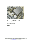
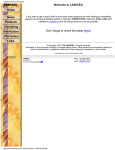
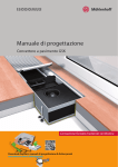
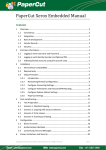
MANUAL
Electric System Convector
ESK 180-110
Content
Product overview.................................................. 2
Scope of Supply................................................. 2
Standard Components...................................... 2 Component for Night Setback Control............ 2
Overview............................................................ 3
Product informations............................................ 4
Intended Use..................................................... 4
Product Description.......................................... 4
Areas of Application......................................... 4
Dimensions........................................................ 5
Technical Data................................................... 5
Identification Label........................................... 5
Preconditions......................................................... 6
Expert Knowledge............................................ 6
Site of Installation . .......................................... 6
Installation Situation........................................ 6
Operating Mode.................................................... 7
Convection Principle......................................... 7
Symbol key
Installation............................................................. 8
Installation Preparation.................................... 8
Height Adjustment ......................................... 8
Free/Full load Capacity...................................... 8
Installation Preparation.................................... 9
Protection Cover............................................... 9
System Extensions............................................. 10
Electrical Connection........................................ 10
Circuit Plan........................................................ 11
Internal Wiring.................................................. 12
Detailed Connection Plan................................. 12
Connection Plan................................................ 13
Designer Grille Roll........................................... 14
Start-up.................................................................. 15
Preparation for Start-up................................... 15
Operation/Use................................................... 15
Maintenance ........................................................ 16
Maintenance/Cleaning...................................... 16
Declaration of Conformity............................... 17
Manual Storage................................................. 17
Technical Support.............................................. 17
Copyright........................................................... 17
Warning: Danger of electrical voltage
Möhlenhoff Wärmetechnik GmbH
Museumstraße 54a
DE-38229 Salzgitter
Germany
Internet: www.moehlenhoff.com
e-mail: [email protected]
Warning: Danger zone
Warning: Hand injuries
Warning: Hot surface
Useful hint/advice
8-D24-53-031.12
ESK 180 -110
Product Overview
Scope of Supply
Standard Components
Alpha Thermostat Standard
AR 2010 S2-S, 230 V, 50/60 Hz
Digital room temperature thermostat for controlling
Alpha-Actuators depending on target and actual temperature.
Electric System Convector
ESK 180-110
OR
Alpha Thermostat Comfort
HANDBUCH
Elektro-Systemkonvektor Heizen
ESK 180-110
Inhalt
Produktübersicht.................................... 2
Lieferumfang ...................................... 2
Standardkomponenten? .................... 2
Optionale Komponenten? ................. 2
Geräteübersicht .................................. 4
Produktinformationen ........................... 5
Bestimmungsgemäße Verwendung .. 5
Produktbeschreibung ........................ 5
Einsatzbereiche .................................. 5
Abmessungen ..................................... 6
Technische Daten ............................... 6
Typenschild ......................................... 6
Konformitätszeichen ......................... 6
Voraussetzungen ................................... 7
Fachkenntnisse ................................... 7
Montageort ........................................ 7
Funktionsweise ...................................... 8
Konvektionsprinzip ............................ 8
Montage ............................................................. 9
Montagevorbereitung ................................... 9
Höhenjustierung ........................................... 9
Freie / volle Begehbarkeit .............................. 9
Installation und Nivellierung ........................ 9
Hydraulischer Anschluss ................................ 10
Heizungstechnische Arbeiten ....................... 11
Elektrischer Anschluss ................................... 11
Leitungsplan .................................................. 12
Interne Verdrahtung ..................................... 13
Detailanschlussplan interne Verdrahtung ... 13
Anschlussplan ................................................ 14
Inbetriebnahme................................................. 15
Voraussetzungen für die Inbetriebnahme .. 15
Bedienung / Betrieb ...................................... 15
Instandhaltung .................................................. 16
Wartung / Reinigung .................................... 16
Aufbewahrung Handbuch ............................ 17
Technischer Service........................................ 17
AR 2010 K2-S, 230 V, 50/60 Hz
Digital room thermostat with operating mode switch for
engaging Alpha-Actuators depending on the target and
actual temperature.
DEU
ENG
RUS
ITA
DAN
Infosymbole
Warnung vor gefährlicher
elektrischer Spannung
Warnung vor
Handverletzungen
Möhlenhoff Wärmetechnik GmbH
Museumstraße 54a
DE-38229 Salzgitter
Warnung vor einer
Gefahrstelle
Hilfreicher Tipp
Internet: www.moehlenhoff.com
E-Mail: [email protected]
Warnung vor heißer
Oberfläche
8-D24-53-030.12
ESK 180-110
Manual
Installation Protection Cover
OR
Alpha Thermostat Control
ENG
AR 2010 C2-S, 230 V, 50/60 Hz
Digital room thermostat with operating mode switch and
plug-in digital clock for engaging Alpha-Actuators depending on the target and actual temperature.
PLUS
Alpha Mounting Base AS 1000
2 x Designer
Roll-Up Grille
with Roll-Up Grille Guard
Mounting Base and electrical connection for AlphaThermostats. Wall and electrical-box mounting
Component for Night Setback Control
Digital Timer – DS 1000
����������������������������������
�
�
�
�
�������������������������������
����������������������������
����
���
���
��
�
2 x JB 8.80 without anchors
4 x JB 8.80 with anchors
Adjustment Blocks 8.80 – Set
2
�
Together with the digital timer, the fan control with room
thermostats and actuators make up for a comfortable and
energy-saving individual room control system.
The 2-channel digital timer controls the desired setback
times. The clearly visible LCD display and the program keys
allow convenient programming of the digital timer.
Product Overview
Overview
4
5
3
ENG
1
2
2
8
9
6
7
1
Endplate
2
Control box ELS 1000
3
System trough
4
Air channeling bar
5
System bulkhead
6
Electrical heating rod
7
Temperature switch and safety fuse
8
Heat exchanger
9
Height Adjustment Blocks
8-D24-53-031.12
3
ESK 180-110
Product Informations
Intended Use
Areas of Application
Möhlenhoff Electric System Convectors are exclusively intended for heating
in closed rooms for covering remaining heat demands, or for the full heating of rooms in case of a corresponding heat demand.
The Electric System Convector ESK is used when the architectural situation
requires an economical and comfortable room heating system. For example, the high glass façades of modern buildings make a cold-air barrier
necessary.
Möhlenhoff under-floor convectors in the ESK series are ideal for the following applications:
• rooms with quick-heating demand
• exhibition rooms
• living areas
• winter gardens
• restaurants
• foyers and entry-halls
• industrial areas
• office and administration buildings
Product Description
The System Convectors from Möhlenhoff are high-quality and high-value
under-floor devices that are precisely manufactured with current and precise technology. The units are securely packed to prevent damage and wear
during shipment.
Through incorrect use or intentional misuse, the Electric System Convector
could pose a danger to the user or a third party.
ENG
The electric system convector is designed for installation in the floor area
(screed level or cavity floor level) and serves for cold air protection in front
of floor-level window facades, or as complete heating system in winter gardens. The electric system convector is not a mobile room heating device;
after the installation it is a part of the building construction. Mains connection must be performed as fixed connection. Height adaptation is possible
by means of adjustment blocks. The convector is covered with a covering
grille which can be removed by hand, the ”designer roll grille”. The designer roll grille is fixed with roll grille protectors.
Möhlenhoff convectors in the ESK product line may not be used in
the following areas:
• in or near areas with danger of explosion (Danger of explosion)
• in wet areas (Danger of malfunction)
• in areas with dusty or corrosive air (Danger of malfunction)
The Designer Roll-Up Grille is subject to availability. For safety reasons, the Linear Grille may not be used in combination with the
Electric System Convector.
4
Product Informations
Identification Label
window side
110
Dimensions
50
HL
KL
180
200
Fensterseite - Window side
Typ: ESK 180-110-1250
ID.-Nr.: ___________________
Auftrag: Pos.:
1-B92-24-200
Bestell Nr.:
0726
The convector lengths KL follow from the combination of heat exchanger that are 500 mm, 1000 mm, and 1250 mm with connection
space on both ends of 250 mm each.
Technical Data
Heat exchanger
Operation voltage
Electric power output
Heat exchanger 500 mm
Heat exchanger 1000 mm
Heat exchanger 1250 mm
Temperature protection switch
electric
Protection class
230 V AC, 50-60 Hz
(see identification label)
220 W
470 W
570 W
Integrated, switch at > 70 °C
Integrated into heat exchanger for protection against defective
thermostats or accidental covering of unit.
up to 3 x 6.3 AT circuit protection in
connection boxes, depending on variant
I
Protection type
IP 20
Safety switch
Fuse*
CE rating
Convector length
Electric plug terminal for
max cable width 2.5 mm
ENG
EN 60335
(see identification label)
Window-view right (left on request)
*Once the fuse is blown, the unit must be reactivated by a qualified craftsman.
8-D24-53-031.12
5
ESK 180-110
Preconditions
Expert Knowledge
Installation Situation
These instructions require special knowledge corresponding to an officially
acknowledged degree in one of the following professions:
- Electrical Equipment Installer or Electronics Engineer
- Systems mechanic for sanitary, heating and air condition technology
according to the profession designations officially announced in the Federal Republic of Germany, as well as according to comparable professions
within the European Community Law.
For the preparation of the manual, a state of knowledge corresponding to
a technician qualification in the mentioned occupational areas, has been
presupposed. Therefore, basic information from these occupational areas is
not described separately.
ENG
1. Continuously elastic border strips
2. Border acoustic insulation
3. Connection line
4. Step-on acoustic insulation
Site of Installation
Möhlenhoff ESK are exclusively intended for a horizontal installation in
floor areas. Möhlenhoff ESK can be installed in dry screed and cast plaster
areas as well as in cavity floors.
If used in areas with mastic asphalt, special measures have to be taken with
respect to temperature shielding, because no part of the ESK may become
warmer than 120°C!
The electrical connection is normally made on the right side of the unit,
when facing the window from the inside.
Screed and flooring, particularly hardwood flooring, can compress
the trough of the under-floor convector due to the thermal properties. We recommend the planning and use of proper insulation during the installation phase.
6
Convection Principle – Natural Convection (Heating)
2
1
ENG
1. cooled air (cold air gradient)
2. warmed air for cold air barrier and room heating
8-D24-53-031.12
7
ESK 180-110
Installation
Installation Preparation
Free/Full load Capacity
1.Carefully remove the ESK from the packaging.
2.Remove the protective covering of the convector trough.
3.Under the protection cover (marked with a point) you will find the
required accessories for connection.
4.The final removal of the trough cover should only be made after
construction is complete.
A
kg
A = 500 mm
kg
A = 400 mm
130
180
Height Adjustment
Top view
Interior adjustment blocks for ESK on the fan side are only available with
a distance of 500 mm.
There are 4 types of Adjustment Blocks for adjusting the height and levelling the convector unit:
The following applies for free/complete step-on ability in case of exterior
adjustment blocks without support:
• capacity up to 130 kg/m if distance between support max 500 mm
• capacity up to 180 kg/m if distance between support max 400 mm
ENG
• Outer Adjustment Blocks
with Feet JBA 8.80
• Outer Adjustment Blocks
with Anchors JBA 8.80
• Inner Adjustment Blocks
with Feet JBI 8.80
• Inner Adjustment Blocks
with Anchors JBI 8.80
6 Adjustment Blocks are included with delivery of each ESK: 3 sets of
Outer Adjustment Blocks.
The number of included Adjustment Blocks (JB) is only enough for levelling purposes! To handle a full load, i.e. for traverse, the ESK must be further supported by either a pressure (and heat) resistant insulation or an
increased number of Adjustment Blocks (see free / full load capacities)!
8
Installation
Installation Preparation
Protection Cover
To prevent the movement or warping of the ESK during the use of
wet or hot screed, we recommend that the unit be anchored in at
least 4 points to the unfinished floor with Adjustment Blocks!
2
Remove the protective cover permanently only after finishing the installation of the system convector and after finishing all building work. By this you
avoid contamination and damage to the system convector.
3
ENG
5
4
1
The electric connection side is marked „•“ on the protective cover.
1
Interior adjustment block: Screw in the threaded bolts
2
Interior adjustment block: Height adjustment
3
Levelling
4
Outer adjustment block: Latch into the trough profile
5
Outer adjustment block: Fix with screws
8-D24-53-031.12
9
ESK 180-110
Installation
System Extensions
Electrical Connection
System Connectors (option)
Note for electrical connection
there are 3 heating element types:
• 220 W
500 mm length
• 470 W
1000 mm length
• 570 W
1250 mm length
All ESK are equipped with the ELS 1000 for the electrical connection.
Through this controller, the resistance and control current are, in relation
to the connection conditions and power, virtually independent. With an AR
40xx, a total of 15 ELS 1000 can be active.
SV
ENG
System connectors serve for connecting two system convector
troughs, or two convector parts, respectively.
Electrical voltage! Danger to life! Disconnect the entire system power
to work on the Electric System Convector!
Push the connectors in even distances into the grooves of the convector
trough. Pull together the convector troughs and fix the connection by means of stud screws M6 and an allen key of size 3.
Mitre Fit
GPS
System convector parts with mitre fit are delivered ready-toplug-in; they are also installed with system connectors.
10
Installation
Circuit Plan
All connection and circuit diagrams are given without electrical protection devices/measures!
AR 2010 S2-S
AR 2010 K2-S
AR 2010 C2-S
DS 1000
AS 1000
Optional controller for temperature setback without an
Alpha-Thermostat Control
8-D24-53-031.12
11
ESK 180-110
ENG
Installation
Internal Wiring
HP 2
HP 3
HP 1
ELS 1000
Connecting box 1
Detailed Connection Plan
ELS 1000
Connecting box 1
PE
N
Heating cartridge HP 2
N'
6,3 AT
Thermostatic switch 2
L' N'
PE
L
N
L
L
1 2 3 4 5 6
Thermostatic switch 3
L'
ENG
N
L
PE
6,3 AT
Alpha Thermostat Comfort
230V AC
N
PE
Thermostatic switch 1
Heating cartridge HP 1
Alpha Mounting Base
AS 1000
12
Heating cartridge HP 3
Installation
Connection Plan
N
L
PE
N'
L' N'
ENG
L'
N'
L' N'
L'
N'
L'
L' N'
Through-connection!
1 2 3 4 5 6
Alpha Thermostat 230 V AC
with Mounting Base AS 1000
External timer with potential-free
contact for the control of reduction
times without Alpha Thermostat
Control, e. g. DS 1000
A further wiring of the mains line via the
connection terminals of the circuit boards is
inadmissible! We therefore recommend corresponding terminals to be provided by the
customer.
8-D24-53-031.12
13
ESK 180-110
Installation
Designer Grille Roll
Designer grille roll protector
Danger of jamming! Always fix
the designer grille roll protector
above the convector fan. It serves as
a protection against reaching into
the fan.
ENG
Fit the designer grille roll into the convector trough in a way that a space
of the size of a grille rod is over the recess in the side parts of the convector.
Insert the protector in a way that its medium part is located above the grille
rod connectors (gummed step-on acoustic insulation) and its exterior fixing
lugs are located below the grille rod connectors.
Insert the designer grille roll into the system convector trough. Using an Allen
key (size 3), push the fixing screws to the outside, and thus, the fixing lugs
into the recesses of the side parts. Finally, tighten the screws.
14
Preparation for Start-up
The ESK cannot be covered by any objects (rugs, furniture, etc.)!
Danger of heat accumulation and damage.
The electrical installation of the entire system, the component of which is
the ESK, was completed as described in this manual.
Electric:
• All power cable and control unit connections have been performed by a
certified electrical tradesman and comply with all current and valid
national standards for electrical devices.
• A check of all the electrical components, including customer specified safety devices, has been successfully performed.
ENG
Operation/Use
Switch on the electric circuit for the power supply of the ESK.
For AR 20xx-x-S, the desired temperature can be set. Further information
can be found in the user manual of the Alpha-Thermostat.
8-D24-53-031.12
15
ESK 180-110
Maintenance
Maintenance/Cleaning
Cleaning intervals
Cover Grille
Ventilation duct
Heat exchanger
The following procedures (1 –3) can be performed by the end user:
ESK
in months
6
6
12
Execution: see
maintenance and
cleaning instructions
see point 1
see point 2
see point 3
1.Clean the Designer Grille
Dry:
Vacuum the Designer Grille at regular cleaning intervals during normal cleaning.
Wet:
Loosen possible grille protectors with a No. 3 Allen
key as shown.
Electrical voltage! Danger to life! Perfom all maintenance and cleaning
work on system convectors only under absence of voltage, in particular
in case or moist or wet cleaning! For this, switch off the corresponding
fuse switches of the voltage supply.
ENG
Designer Roll-Up Grille: Roll the cover-grill up without bending or kinking.
• Clean in Washing Machine: The DR is washing machine safe evenly up to a temperature of 60°C with normal (non-industrial strength) dish-
washer cleaner. After washing and drying,the grille can be replaced on the convector trough and re-secured.
• Cleaning without Washing Machine: Remove the grille from the
convector and unroll in a place where it can be cleaned. For cleaning, we
recommend normal detergent and, if needed, a soft cleaning brush.
After washing and drying, the grille can be replaced on the convector
trough and re-secured.
2.Clean the Convector Trough
Remove the Designer Grille and, if needed, the filter. To clean the hand-accessible area of the trough, we recommend a dry dust cloth or broom. Hard to reach
places can be cleaned with a vacuum cleaner (a soft brush nozzle can be useful).
Difficult to remove dirt can be removed with a moist towel. Replace the filter, if
needed, and the Designer Grille.
Danger of burns! Be always very careful during maintenance and repair work near the heat exchanger. The heat exchanger can become
very hot depending on its state of operation.
Danger of injuries! Ensure during maintenance and cleaning work that
no persons or animals step into or enter the open system convectors.
16
Maintenance
Manual storage
3.Clean the Heat Exchanger
Remove the Designer Grille. To clean the hand-accessible area of the heat
exchanger, we recommend a dry dust cloth or broom. Hard to reach places
can be cleaned with a vacuum cleaner equipped with a soft brush nozzle or
a soft brush. Replace the filter, if needed, and the Designer Grille.
All trades participating on the installation, connection and commissioning of the ESK need information from this manual in order
to perform their work. Please ensure that the manual is disclosed
correspondingly after the termination of the individual parts of the
work.
Please give this manual to the later users as a document for revision in the
scope of commissioning and hand over of the equipment, because it includes important notes on maintenance and care.
Danger of injuries! Do not forget to
secure the Designer grille roll!
Technical Support
Technical support
Mo to Thu: 7:30 to 17:00 Uhr
Fr: 7:30 to 15:00 Uhr
Service-Telephone: +49 (0) 53 41 8475 - 470
Service-Fax: +49 (0) 53 41 8475 - 999
E-Mail: [email protected]
Mailing Address
Möhlenhoff Wärmetechnik GmbH
Techniscal Support
Museumstraße 54a
DE 38229 Salzgitter
Germany
Declaration of Conformity
The manufacturer declares in sole responsibility that the product
ESK complies with all applicable requirements of the guidelines
2004/108/EG and 2006/95/EG.
The following standards were used for the assessment:
• EN 60335-1:2002
• EN 60335-2-30:2003+A1:2004
ENG
Copyright
This manual is protected by copyright. All rights reserved. It may not be
copied, reproduced, abbreviated or transmitted, neither in whole nor in
parts, in any form, neither mechanically nor electronically, without the previous consent of the manufacturer. The basing information was evaluated
thoroughly and arranged to the best knowledge.
© Copyright 2009
8-D24-53-031.12
17
ESK 180-110
ENG
18
ENG
8-D24-53-031.12
19
ESK 180-110