1
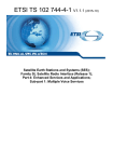
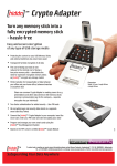
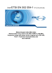
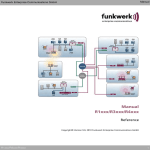
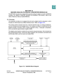
UDSS Universal DECT Secury System • Professional Emergency Signal System for Personal Security in hazardous areas and for lone workers • Message and telemetry handling system for direct communication with all portable handsets Technical Information Brochure 2 Document type Technical Information Brochure Product UDSS: Universal DECT Secury System Publisher Funkwerk Security Communications GmbH John-F.-Kennedy-Str. 43-53 D-38228 Salzgitter Phone:+49 5341 2235-0 Fax: +49 5341 2235-709 This document is protected by copyright.. All rights reserved. The copying, distribution, translation or conversion of this document in its entirety or any part thereof, whether in electronic or otherwise machine-readable form, is not permitted without the permission of Funkwerk Security Communications GmbH. Subject to alteration without notice. Suggestions and enquiries ... regarding this technical information brochure or products should kindly be directed to the above address Last amendment 10.05.2012 Technical Information Brochure Universal DECT Secury System 10.05.2012 3 Table of Contents Table of Contents 1 Functional Description of UDSS .......................................................................................................... 4 1.1 What is UDSS? ..................................................................................................................... 4 1.2 Personal Emergency Signal Functionality ............................................................................ 6 1.3 Messaging ............................................................................................................................ 7 1.4 Operational requirements ..................................................................................................... 8 1.5 Operation of the UDSS ......................................................................................................... 9 1.6 UDSS supported by Inductive Localisation Beacons .......................................................... 10 1.7 Alarms ................................................................................................................................. 11 1.7.1 Alarm types ............................................................................................................. 11 1.7.2 Alarm parameters ................................................................................................... 13 1.7.3 Login and log-off in the secure Secury mode ......................................................... 14 1.8 Localisation of personnel .................................................................................................... 15 1.9 Alarm Activation .................................................................................................................. 16 1.9.1 Schematic representation ....................................................................................... 17 1.9.2 Processing an alarm ............................................................................................... 18 1.9.3 Expanded alarm procedures .................................................................................. 19 1.10 Application limits ................................................................................................................ 19 1.11 Scope of supply ................................................................................................................. 19 1.12 Commissioning .................................................................................................................. 20 2 UDSS Server ........................................................................................................................................ 21 2.1 Overview ............................................................................................................................. 21 2.2 Function .............................................................................................................................. 21 2.3 Connection type .................................................................................................................. 21 2.4 Secury Software ................................................................................................................. 22 2.4.1 Overview ................................................................................................................. 22 2.4.2 Configuration and Operation .................................................................................. 22 2.4.3 Warden’s Rounds Command and Control System (optional) ................................. 23 2.5 Guard module versions ....................................................................................................... 24 3 Handsets 3.1 3.2 3.3 3.4 3.5 .............................................................................................................................................. 25 Technical data .................................................................................................................... 25 Handsets | Messaging-only Function .................................................................................. 26 Handsets | Alarm Function .................................................................................................. 27 MemCard ............................................................................................................................ 27 Accessories and enhancements ......................................................................................... 27 4 Inductive Localisation Beacon ........................................................................................................... 28 4.1 Overview ............................................................................................................................. 28 4.2 Function .............................................................................................................................. 28 4.3 Properties ........................................................................................................................... 29 4.4 Technical data .................................................................................................................... 29 4.5 Accessories and Spares ..................................................................................................... 30 5 Application examples.......................................................................................................................... 31 5.1 Mid-sized retail business .................................................................................................... 31 5.1.1 Technical Service ................................................................................................... 31 5.1.2 Security Personnel and House Detectives ............................................................. 31 5.2 Mid-sized business in the recycling industry ....................................................................... 33 5.2.1 Machine operators and assistants .......................................................................... 33 5.2.2 Electrician and mechanic ........................................................................................ 33 6 Abbreviations....................................................................................................................................... 35 Technical Information Brochure Universal DECT Secury System 10.05.2012 4 What is UDSS? Functional Description of UDSS 1 Functional Description of UDSS 1.1 What is UDSS? Funkwerk Security Communications now offers you the full performance package of a professional personal emergency signal (PES) system with competitive operating costs: the UDSS versions of the latest Funkwerk FC 4 DECT handset generation employ standardised transmission mechanisms and can be fully integrated with GAP-DECT systems. A multiplicity of performance features is available to ensure the personal security of your employees, allowing optimal adaptation to your individual requirements – including the precise localisation of casualties. Alarm events are shown clearly at the control centre, enabling an immediate appreciation of situations, even though they may be complex. Appropriate measures can then be taken. Devices equipped with high-performances sensors recognise certain hazardous situations automatically and send the corresponding alarm, with an exact position of the incident, directly to the control centre or the handsets of the emergency response team. In addition to the personal emergency signal functionality, the UDSS also has messaging features, allowing the operators to send manual messages. In the event of machine or personal alarms, messages are automatically sent to the DECT handsets. Intrinsically safe (explosion-proof) versions of the FC4 are available for use in environments with a high explosion risk, be it due to a gas or dust atmosphere. The speech channel of an active telephone call is used to exchange information between the UDSS server and the handsets for the messaging, personal security and localisation features. Data is transferred in-band by means of a special modulation technique. To enable the UDSS server and the handsets to react very rapidly, Calling Line Identification Presentation (CLIP) is required. Technical Information Brochure Universal DECT Secury System 10.05.2012 What is UDSS? 5 Functional Description of UDSS ILB Server connection via the S0 subscriber connection DECT-login and handover compliant with GAP/CAP Telephone exchange UDSS server FC4 U | FC4 Alarm relay via speech channel on DECT network Acknowledgement via speech channel on DECT network Functional Structure In the case of a personal alarm, a technical device alarm or a beacon-based (ILB) localisation report, the mobile device opens a speech channel to the ISDN card of the UDSS. The relevant UDSS server MSN is initially defined in the system and preconfigured as a data sink in all the UDSS devices. The addressed UDSS server accepts the call immediately and then awaits the modulated telegram data. This data is then analysed by the UDSS server and is indicated in text and on a floor-plan at the alarm control centre, as well as being relayed to the handsets. Technical Information Brochure Universal DECT Secury System 10.05.2012 6 Personal Emergency Signal Functionality Functional Description of UDSS 1.2 Personal Emergency Signal Functionality By using a personal emergency signal system, the risk of injury to personnel can be minimised and damage to property can be avoided. In accordance with the directives of the German Employers’ Insurance Association regarding personal emergency signal systems (BGR 139), as well as DIN VDE 08251, the Funkwerk UDSS can be used to safeguard the personal security of lone workers. The automatic, sensor-based recognition of emergency situations by the DECT handsets, and the automatic relay of alarms to other active personal emergency signal devices in the system, enables assistance. to be rendered rapidly. • Compatible with existing and new systems • Compatible with standard DECT systems (GAP/CAP) • User-friendly display of alarms and alarm management • The precise localisation of a casualty (using the optional ILB) enables an accurate position to be displayed on the floor-plan of the alarm management system • Rescue services can be guided directly to the accident site by means of the alarm, together with the location, being relayed to mobile units • Cyclic monitoring of the radio signal coverage and the functionality of the device ensures serviceability • Remote-controlled eavesdropping function in the event of an alarm • Server-based alarm indication and alarm management • Connection to commercial telephone exchanges via ISDN subscriber terminal Technical Information Brochure Universal DECT Secury System 10.05.2012 Messaging 7 Functional Description of UDSS 1.3 Messaging The messaging feature of the Funkwerk UDSS makes it possible to send text messages and numerical sequences wirelessly between users. The UDSS server enables messaging between: • system handsets of an existing DECT system • system handsets and external messaging sources and destinations that have system-compliant interfaces with the UDSS server. • The alarm is displayed at the alarm management point of the UDSS server. The UDSS server is an addition to the telephone exchange infrastructure and its capabilities include messaging as well as several Secury functions. It directs the process of messaging to the DECT handsets and enables the connect of systemcompliant personal paging systems. Users can manually create individual text messages via the alarm management point or retrieve defined texts from clients or handsets. These texts can then be sent to individual subscribers, groups or all subscribers. If an alarm message is generated by a particular machine, a text message can be sent automatically to the responsible employee. The content of the message must be predefined and assigned. In this way, all relevant information can be conveyed: for example, the designation of the machine, its location and the error code of the alarm. To indicate the various levels of urgency of the messages, it is possible to set up further programming in addition to the standard signalling. The standard signalling of all call types is a vibration alarm as well display and keypad illumination. The melody, display duration, signal duration and the signal volume can be set individually for each call type. PLEASE NOTE Further information regarding the topic of messaging can be found in the “Funkwerk Professional Messaging” document. Technical Information Brochure Universal DECT Secury System 10.05.2012 8 Operational requirements Functional Description of UDSS 1.4 Operational requirements In order to operate a Funkwerk UDSS, a telephone system with a DECT wireless capability that supports DECT GAP/CAP and CLIP features is required. The Funkwerk UDSS is integrated with the DECT network supplied by the client by means of the internal S0-bus of the telephone exchange. The CLIP feature is a basic requirement for the operation of the UDSS and must, if required, be subjected to a system test prior to delivery. A list of tested exchanges is available under the Partner tab of the Funkwerk website. Example of a customer-supplied telephone exchange system Legend Symbol Meaning and features Customer-supplied telephone exchange with GAP/CAP and CLIP features Connection cable for the DECT stations and DECT Repeater Telephone network (optional) DECT station or DECT repeater Technical Information Brochure Universal DECT Secury System 10.05.2012 Operation of the UDSS 9 Functional Description of UDSS 1.5 Operation of the UDSS The UDSS server is linked to the internal S0 bus of the telephone exchange. The UDSS server uses the existing DECT system as a communication path to the terminals. In order to be able to use the functions of the UDSS, Funkwerk DECT handsets are required, see the section on „Handsets“ (Page 25). Connection between the UDSS and the existing telephone exchange Legend Symbol Meaning and features UDSS server – see chapter „UDSS Server“ (Page 21) on UDSS server,. S0-connection cable between the UDSS server and the internal S0-bus on the existing telephone exchange Customer-supplied user-interfaces (monitor, keyboard, mouse) Technical Information Brochure Universal DECT Secury System 10.05.2012 10 UDSS supported by Inductive Localisation Beacons Functional Description of UDSS 1.6 UDSS supported by Inductive Localisation Beacons Inductive localisation beacons (ILB) can be used for the precise localisation of personnel. The more ILBs that are installed, the more precisely a person can be localised. In order to operate, the ILBs need only be supplied with electrical current (24 V or 230 V). Further information regarding ILBs can be found in the chapter on „Inductive Localisation Beacon“ (Page 28). In the standard configuration, information regarding the immediate position of a handset is only transmitted to the UDSS server in the event of an emergency. If required by the client, continuous monitoring is possible – see the section „Warden’s Rounds Command and Control System (optional)“ (Page 23). The type of monitoring depends on the programming of the terminals. UDSS supported by Inductive Localisation Beacons Legend Symbol Meaning and features Inductive localisation beacon (ILB) continually transmits unique localisation codes in a defined area Technical Information Brochure Universal DECT Secury System 10.05.2012 Alarms 11 Functional Description of UDSS 1.7 Alarms The mobile personal emergency signal devices are equipped with manual and automatic alarm triggers. The manual alarms are at first only indicated locally by means of an aural signal on the mobile device that triggered the alarm (pre-alarm). In order to prevent false alarms, the pre-alarm can be cancelled within a pre-set reaction time by the user. 1.7.1 Alarm types Manual modes Alarm Alarm designation Application Pushbutton alarm 1: Single touch of the button Active Alarm: Observed danger Pushbutton alarm 2: Button pressed 3 times Active Alarm: Observed danger Warning alarm 1: Single touch of the button Request for support, call for assistance Warning alarm 2: Button pressed 3 times Request for support, call for assistance Alarm designation Application Loss alarm Tag is torn away Detection of an attack situation: (Seizure of device) Automatic alarm modes Alarm Position alarm Fall or feinting Device is tilted at least 55º Technical Information Brochure Universal DECT Secury System 10.05.2012 12 Alarms Functional Description of UDSS Automatic alarm modes (cont'd) Alarm Alarm designation Application Time-out alarm Periodic testing for activity A pre-programmed key is not pressedafter a predefined time has elapsed Man-down alarm: Device is static and is not moved within a predefined period of time Lack of movement (Person is trapped or unconscious in a seated position) The reporting parameters of each alarm mode are individually programmable in terms of: • reaction time • pre-alarm time • aural alarm signal sequence and volume • signal and display duration Technical Information Brochure Universal DECT Secury System 10.05.2012 Alarms 13 Functional Description of UDSS 1.7.2 Alarm parameters All alarm parameters are configured in a programming tool and are saved to the memory card of the device via the USB MemCard dongle or a special programming cable. The user can have all the alarm parameters displayed in a PIN-secured Secury menu. This has the advantage that in the event of a devices being swapped, the new device can be taken into use immediately simply by exchanging the MemCard. Config software Technical Information Brochure Universal DECT Secury System 10.05.2012 14 Alarms Functional Description of UDSS 1.7.3 Login and log-off in the secure Secury mode Directly after removing the FC4 U device from the desk-top charger, the user is required to test all active (as enabled by the programming of the device) security sensors. If required by the customer, the commencement of the start-up test can also be carried out manually by means of an appropriate menu. Only after the successful completion of the start-up test will the device automatically login to the UDSS server. This test process is performed each time the device is taken into service or at least once every 24 hours. The cyclic monitoring of the connection between the handset and the UDSS server now begins. During this monitoring, the handsets are continuously tested for device faults. If a device develops a fault or reports a communication failure, then this information is reported immediately. Log-off occurs automatically when the device is placed in the desk-top charger. Cyclic monitoring of this FC4 device then ceases. As with login, log-off can also be performed manually by means of a menu selection. Cyclic monitoring of this FC4 U device then ceases. As with login, log-off can also be performed manually by means of a menu selection. PLEASE NOTE Automatic testing of individual sensors and automatic login can also be switched off, if the customer so requires. Technical Information Brochure Universal DECT Secury System 10.05.2012 Localisation of personnel 15 Functional Description of UDSS 1.8 Localisation of personnel In order to localise personnel in the field, the UDSS must be aware of the actual position of the mobile devices being carried, thus determining the locality of each individual. A permanently installed network of inductive localisation beacons (ILBs) is required to enable localisation. Already when the DECT handset is logged-on to the secure mode, the user is required to enter the signal field of an ILB (this requirement can be switched off as an option). Each permanently installed ILB continually transmits a unique localisation code. The transmission ranges of the ILBs do not overlap and cover an area of only a few square metres (transmission range can be preset). On leaving one transmission range and entering another, the newly-acquired localisation code is detected and saved by the handset. The last three ILB-codes are memorised by the handset. In the event of an alarm, the last-saved ILB codes are transmitted to the UDSS server. The direction of movement can be extrapolated from this data. The actual position is indicated at the alarm management point of the UDSS server by means of a symbol on the floor-plan and as text. Secury software display (screen-grab) indicating precise localisation by means of localisation beacons. The use of inductive localisation beacons makes room-specific localisation possible. Further information regarding the ILBs and examples of the configurations can be found in the section „Inductive Localisation Beacon“ (Page 28). Technical Information Brochure Universal DECT Secury System 10.05.2012 16 Alarm Activation Functional Description of UDSS 1.9 Alarm Activation If an FC4 U sensor detects an alarm situation or if the user triggers an alarm manually, the handset transmits an appropriate alarm telegram. The telegram includes the most recently received ILB code (site of the alarm) and the type of alarm. The base station or the repeater in whose reception area the alarm has been activated relays the alarm to the UDSS server. Alarm activation takes place by means of a dial-up connection between the handset and the UDSS server. The UDSS server evaluates the alarm telegram. The ILB code is converted into appropriately configured text information. The received alarm is displayed in graphic and/or text form at the alarm management point of the UDSS server. A server acknowledgement is sent to the handset initiating the alarm. All in-coming alarms reports are saved as a data set in a database transaction table. At any stage, a history of alarm reports can be requested from the alarm management point of the UDSS server for subsequent evaluation. If the control point is not manned continuously, then all alarms can also be relayed via messaging to other devices in the field. In this case, the location report is displayed as text. Depending on the configuration, an alarm can also be relayed to external devices (not connected to the DECT system): for example, to mobile radios or landline telephones or in the form of e-mail. Technical Information Brochure Universal DECT Secury System 10.05.2012 Alarm Activation 17 Functional Description of UDSS 1.9.1 Schematic representation Schematic representation Legend Symbol Meaning and features Call for help / alarm activation Message is relayed Assistance is dispatched Technical Information Brochure Universal DECT Secury System 10.05.2012 18 Alarm Activation Functional Description of UDSS 1.9.2 Processing an alarm Having received an alarm at the alarm management point of the UDSS server, the personnel are required to take four processing steps. The procedure requires that the following steps be executed: 1. The alarm in progress must be cancelled actively via the Secury software. The message H ELP IS ON ITS WAY is displayed on the handset that initiated the alarm. This indicates to the user who initiated the alarm that the alarm is being processed and that assistance intervention is being initiated. On successful transmission of the display message, the handset that initiated the alarm automatically sends confirmation to the UDSS server. 2. On completion of the rescue or assistance intervention, the person in charge must issue a positive reset-authorisation for the relevant handset via the Secury software. Resetting can also take place on the move from FC4U or FC4 handsets. The message A LARM ENDED is displayed on the handset that initiated the alarm. On successful transmission of the display message, the handset that initiated the alarm automatically sends confirmation to the UDSS server. 3. The alarm must be reset by means of a softkey on the handset that initiated the alarm. Once the alarm has been reset successfully, the handset that initiated the alarm automatically sends confirmation to the UDSS server. 4. Finally, once processing of the alarm has been completed by means of an annotation entry at the alarm control point of the UDSS server, it is deleted from the report list. Done. PLEASE NOTE Resetting can also take place on the move from FC4U or FC4 handsets. Technical Information Brochure Universal DECT Secury System 10.05.2012 Application limits 19 Functional Description of UDSS 1.9.3 Expanded alarm procedures The alarm procedure can be altered to suit the requirements of the customer. Thus it is possible in an emergency, to activate the speaker mode of the handset without any intervention by the user being required. (This function can also be remotely controlled.) In the event of hostage-taking, it makes sense to mute the handset and not allow the device to display any indication that help is on its way. Simultaneously, the handset can be switched to an eavesdropping mode, which cannot be recognised on the handset. If the control point cannot be manned continuously, escalation scenarios can be defined on the UDSS server. The UDSS also provides for the automatic relaying of outgoing alarms as messages to other handsets. In this way, the person responsible for responding to the alarm is notified of an emergency situation within seconds by means of a display report. The message contains information reporting the sender, the type of alarm as well as the location of the alarm. The alerted personnel can then hurry directly to the location of the alarm or man the UDSS server alarm control point, in order to deal with the alarm. If the alarm is not processed at the alarm control point within a predefined time, the UDSS offers the possibility of escalating the alarms. These escalation scenarios are defined according to the customer’s requirements. For example, warning lights and sirens can be switched on after a preset acknowledgement time has elapsed, or the alarm can be relayed to GSM devices or be e-mail. Even extensive relay scenarios can be achieved by means of a script. 1.10 Application limits If the Funkwerk UDSS is used as a personal emergency signal system, a maximum of 30 Funkwerk FC4 U DECT handsets with a personal emergency signal function can be operated simultaneously via the UDSS server. The management of larger systems requires the Funkwerk DSS. Further information regarding the Funkwerk DSS is available on request. 1.11 Scope of supply The following elements are included in the scope of delivery of the UDSS: • A UDSS server (industrial PC- with operating system installed and Secury software (ready to configure) • A licence dongle • An installed and pre-configured S0 card • A power cable for the UDSS server • A back-up CD with user manual. Technical Information Brochure Universal DECT Secury System 10.05.2012 20 Commissioning Functional Description of UDSS 1.12 Commissioning Preparing the UDSS server for operation The procedure requires that the following steps be executed: 1. The UDSS server must be connected to the existing telephone exchange via the internal S0- bus. 2. Customer-supplied user interfaces (monitor, keyboard and mouse) are connected to the UDSS server. 3. The UDSS server is powered up. The server boots up All the necessary software tools start automatically 4. Login to the UDSS server User: Operations mode in this mode no settings are possible Administrator mode: This mode is used to configure the system. 5. Enter the MSN of the UDSS server into the software tool on the server. 6. Test the connection between the UDSS server and the telephone exchange by means of the software tools. UDSS server is now operational. Login of handsets to DECT network The procedure requires that the following steps be executed: Systems-dependent login of handsets to the DECT network Handsets logged-in to system Login of FC4 U handsets to server The procedure requires that the following steps be executed: FC4 U handsets are set to the Secury mode Login takes place automatically on the UDSS server FC4 U handsets now logged-in to server Configuration The procedure requires that the following steps be executed: process of the UDSS server Customer-specific configuration of the Secury server software and the handsets is executed (floor-plans, call groups, handset designations etc) UDSS server is configured Done. PLEASE NOTE A comprehensive start-up and initial configuration guide is included with the system. Technical Information Brochure Universal DECT Secury System 10.05.2012 Overview 21 UDSS Server 2 UDSS Server 2.1 Overview UDSS server This illustration of a UDSS server is purely an example, and the design of the device as delivered may be different. 2.2 Function The Secury software is installed on the UDSS server and it is used to process and display alarm events. The UDSS server is linked to the internal So bus of the customer-supplied telephone exchange. The UDSS server communicates with the Funkwerk FC4 handsets via the existing DECT network. 2.3 Connection type The industrial PC contains an ISDN card, which must be connected to the internal So bus of the telephone exchange. In addition to logic inputs such as a door contact switch, the UDSS server is also equipped with external interfaces, which support the following protocols: • OPC protocol • ALPHA-2 protocol (LAN) • ESPA 4.4.4 protocol These interfaces can be controlled serially or via LAN. Technical Information Brochure Universal DECT Secury System 10.05.2012 22 Secury Software UDSS Server 2.4 Secury Software The Funkwerk Secury software enables the display of incoming alarms overlaid upon predefined floor-plans. In the event of a personal alarm being activated, the operator at the alarm control point of the UDSS server can immediately see the location of the alarm on the screen, summon help and coordinate operations. All events are captured by the software, recorded and saved in a database. Once the alarm has been processed, the operator must enter a concluding comment regarding the alarm processing. 2.4.1 Overview Secury Software 2.4.2 Configuration and Operation Once the UDSS server has booted up, the user is asked to enter a login name and a password. Depending on the authorisation status of the user, one of two display modes appears on the screen: The Secury software has two display modes with differentiated access-rights • the operator display-mode • the administrator display-mode 2.4.2.1 Operator display-mode Here no settings can be altered. This display mode is used for day-to-day operations. Floor-plans can be retrieved but not altered. All handsets registered on the UDSS server can be seen. Logged-in handsets are indicated in another colour to those that are not logged-in. In this display mode, new devices cannot be added. 2.4.2.2 Administrator display-mode This display mode enables system configuration to be carried out. Floor-plans saved on the server are linked via the software to the identifiers of the inductive localisation beacons. The DECT handsets are administered here and a unique designation (for example “Electrician”) can be assigned to each individual handset. Technical Information Brochure Universal DECT Secury System 10.05.2012 Secury Software 23 UDSS Server 2.4.3 Warden’s Rounds Command and Control System (optional) The “Warden’s Rounds Command and Control System” software module completes the comprehensive control and protocol functions of the Secury software with the active and automated control of guard personnel. This software module enables a completely new type of operational organisation of the security service. Routine patrols on the same beat can be spied upon and this information then used for criminal purposes. The Warden’s Rounds Command and Control System assists in this regard by means of randomly-assigned patrol instructions. The guard patrols can be altered to suit actual requirements. Decentralised time clocks and cards are no longer required; instead the ILBs can be used as contact-less control points by means of special identifiers. The “Warden’s Rounds Command and Control System” lightens the management load thanks to the following features: • Pre-programmed guard patrols can be assigned manually or randomly • Many guard patrols can be managed and monitored simultaneously • On passing a checkpoint, the next checkpoint (with timing) is automatically indicated on the guard’s handset • The required actions are automatically displayed on the guard’s handset at the correct time and place • When a guard passes a checkpoint the location and time details are automatically sent to the UDSS server • Monitoring and logging of localisation and alarms • Control of the guard patrols by means of ad-hoc messages sent to the devices of the guards. Technical Information Brochure Universal DECT Secury System 10.05.2012 24 Guard module versions UDSS Server 2.5 Guard module versions Guard Module Versions Designation Information Item number WGS 2 Guard module, software licence for up to 2 guard control terminals: • up to 100 different beats can be administered (patrols with predetermined times and/or predetermined locations) • guard patrols can be initiated manually or automatically • guard alarms can be processed, also via the Webnet application • automatic recording of various parameters 5.010.403.010 WGS 5 Guard module, software licence for up to 5 guard control terminals: • up to 100 different beats can be administered (patrols with predetermined times and/or predetermined locations) • guard patrols can be initiated manually or automatically • guard alarms can be processed, also via the Webnet application • automatic recording of various parameters 5.010.403.011 WGS 10 Guard module, software licence for up to 10 guard control terminals: • up to 100 different beats can be administered (patrols with predetermined times and/or predetermined locations) • guard patrols can be initiated manually or automatically • guard alarms can be processed, also via the Webnet application • automatic recording of various parameters 5.010.403.012 WGS 100 Guard module, software licence for up to 999 guard control terminals: • up to 100 different beats can be administered (patrols with predetermined times and/or predetermined locations) • guard patrols can be initiated manually or automatically • guard alarms can be processed, also via the Webnet application • automatic recording of various parameters 5.010.403.013 Technical Information Brochure Universal DECT Secury System 10.05.2012 Technical data 25 Handsets 3 Handsets Depending on the specific field of application, clients may choose between six Funkwerk FC4 DECT handsets for use with a Funkwerk UDSS. Each of these handsets has its own individual characteristics, which differentiate it from the other devices. 3.1 Technical data The following technical data applies to all FC4 DECT handsets, while specialised specifications can be found in the product brochure of the handset concerned. Dimensions Size (l x b x h) approx. 141 – 168 x 47 x 35mm (with clip) Weight approx. 106 – 155g Protection class and temperature range EX protection zones 1 and Gas - complies with ATEX 94/9/EG: II 2 G Ex ib IIC T4 21 Dust - complies with ATEX 94/9/EG: II 2 D Ex ibD 21 T125 °C IP6 x IP protection class IP 65 (jet-proof and dust-tight) Operating temperature range Operable between -10 and + 50 ºC Power supply Lithium-ion rechargeable battery 3,7V / 650mAh (screw-secured in PES and Ex versions Charging time approx 5 hours Battery life Stand-by 25 – 100 hours (with / without idle display lighting) Continuous talk time 10 – 15 hours (with / without idle display lighting) DECTTM-HF Frequency range 1,88 to 1,9 GHz Transmitting performance average: 10 mW, Peak: 250mW Acoustics Aural signalling up to 100 dB(A) (Ex versions – up to 94 dB(A) at a distance of 30cm Loudspeaker rear-mounted Hands-free very good audibility Vibration signalling supplementary or mute signalling Technical Information Brochure Universal DECT Secury System 10.05.2012 26 Handsets | Messaging-only Function Handsets 3.2 Handsets | Messaging-only Function Handsets | Messaging-only Function Illustration Designation Special features D4 Office • Slot-in battery for rapid replacement • Further information can be found in the product brochure • Jet-proof and dust-tight (IP 65) • Further information can be found in the product brochure • ATEX-certified DECT industrial handset • Can be used with a headset • Further information can be found in the product brochure • Device is easy to disinfect • Further information can be found in the product brochure FC4 FC4 Ex HS FC4 Medical Technical Information Brochure Universal DECT Secury System 10.05.2012 Handsets | Alarm Function 27 Handsets 3.3 Handsets | Alarm Function Handsets | Alarm Function Illustration Designation Special features FC4 U • Jet-proof and dust-tight (IP 65) • Various alarm types (push-button, position, mandown, time-out alarm) • Further information can be found in the product brochure • ATEX-certified DECT industrial handset • Can be used with a headset • Various alarm types (push-button, position, mandown, time-out alarm) • Further information can be found in the product brochure FC4 U Ex HS 3.4 MemCard All user settings, alarm parameters, call histories as well as all saved messages (received or sent) are saved on the memory card. This simplifies the exchange of defective devices, as all user data is saved on the card and not the handset. Intervention by a technician is therefore not required. MemCard (SIM card) 3.5 Accessories and enhancements Information regarding the separately available accessories and enhancements can be found in the relevant product brochures. Technical Information Brochure Universal DECT Secury System 10.05.2012 28 Overview Inductive Localisation Beacon 4 Inductive Localisation Beacon 4.1 Overview Inductive Localisation Beacon 4.2 Function Inductive localisation beacons (ILBs) enable an operator to localise the exact position of a person needing emergency assistance. In this way the current position of the user can be displayed with precision via the Secury software on the UDSS server. The ILB need only be connected to a power supply (either (24 V or 230 V). Each ILB is wirelessly configured by means of a configuration tool (available separately). Thereafter the ILB continually transmits a unique localisation code within its signal field. The signal field can be precisely set without opening the casing, even in the case of sabotage-proof surface mounting. Technical Information Brochure Universal DECT Secury System 10.05.2012 Properties 29 Inductive Localisation Beacon 4.3 Properties The inductive localisation beacon (ILB) has the following properties: • low frequency, anechoic and attenuation-free localisation method with purely magnetic coupling between transmitter and receiver coils (induction) • range from 0,7m to 6m (programmable) • address range: 10 000 addresses • programming of addresses and range possible without opening the casing • recognition of direction of movement by separate antenna (optional) • external loop antennas, recessed below surface • functional monitoring of the ILB with alarm via accessory module (optional) • sabotage alarm • sabotage-proof installation (optional) • ATEX certification (optional) 4.4 Technical data The following information pertains to the standard IOS 452 device Dimensions Size (l x b x h) 200 x 120 x 60mm (approx.) Protection class and temperature range EX protection (optional) IIC T4 (IOS 451, Article No 7.770.029.502) IP protection class IP 65 (jet-proof and dust-tight), suitable for outdoor use and surface mounts) Operating temperature range Can be operated between -15 and + 55 ºC Power supply Mains supply 230 V AC, 50 - 60 Hz or 24 V DC Power consumption approx 10W Technical Information Brochure Universal DECT Secury System 10.05.2012 30 Accessories and Spares Inductive Localisation Beacon 4.5 Accessories and Spares Accessories Designation Information Item number Configuration Tool For inductive localisation beacons IOS451 and IOS452 4.999.017.053 Supplementary antenna for IOS452 With 10m connecting cable (can be shortened or lengthened up to 20m if required) 5.010.272.000 Accessory kit for IOS452 Loop connectors for cable loops shorter than 30m 5.010.274.000 Filter for inductive cable loops Inductive cable loops with a length exceeding 30m must be registered with the Federal Network Agency IOF 452 localisation filter for Enclosed, for IOS452, without monitoring of the ILB loops longer than 30m Not enclosed, for IOS452, without monitoring of the ILB Warning sign for ILB 5.010.273.000 5.010.273.800 Warning sign is required for persons with pacemakers Persons with 5.010.271.500 pacemakers must remain at least 20cm away from an ILB. Further information can be found in the ILB documentation. Contents: 10 pieces Spares Designation Information Item number Ferrite antenna - 7.770.097.201 Cable (blue) for external ILB per metre antennas Technical Information Brochure Universal DECT Secury System 10.05.2012 4.999.054.309 Mid-sized retail business 31 Application examples 5 Application examples 5.1 Mid-sized retail business As an example, let us consider the case of a mid-sized clothing business with a number of sales floors. In addition to salespeople, administration, management and union representatives, a technical service and internal security personnel are also accommodated. There is an existing DECT network installed in the building complex. This network is used by the employees to communicate with one another as well as making calls on the public telephone network. This application example will illustrate how the Funkwerk UDSS can be used to support the in the execution and optimisation of their duties. 5.1.1 Technical Service The employees of the technical service are responsible for dealing with internal technical problems. For example, if there is an operational fault in the ventilation system, a fault report is automatically sent to a fault report server. Until now, the technical service employees have had to either access these reports manually, or be informed telephonically by other employees. This is where the Funkwerk UDSS can make a difference. Each employee receives a Funkwerk DECT handset for communication with both the internal DECT as well as the public telephone networks. The fault report server is connected to the Funkwerk UDSS server via an interface. Now it is the UDSS server that accepts the incoming fault report alarm and relays it to the technical services employees via the DECT network. A message detailing the fault report and the location of the fault is displayed on the handsets of the technical services. They now have real-time knowledge of the fault and can react promptly to deal with operational problems. This saves time and money and, thanks to the rapid exchange of information, prevents further operational faults. 5.1.2 Security Personnel and House Detectives Located in the internal security control room, house detectives monitor by means of closed-circuit cameras what is happening in the sales rooms. At the same time, other detectives move independently through the sales departments. In the event of a theft being observed, the detectives detain the culprit – which can result in physical confrontation. This can now be prevented. Should a detective recognise a theft in progress, he can trigger a silent alarm on his Funkwerk FC4 U handset. The Funkwerk UDSS server receives the incoming request for assistance via the DECT network. The UDSS server relays the alarm to other deployed detectives or to the security personnel. This is indicated on the handsets of the house detectives either in mute mode or by means of a vibrating alarm. Thus, additional detectives as well as security personnel can quickly move in to arrest the suspect. Technical Information Brochure Universal DECT Secury System 10.05.2012 32 Mid-sized retail business Application examples But that is not all. Safety regulations for public buildings prescribe escape routes in the event of fire. The escape routes head towards fire doors. These doors are locked from the outside and in the event of a fire must be opened from the inside without any difficulty. For this reason, the doors are fitted with alarms. Thieves often make use of this opportunity to escape from the building with their loot. Here too, the Funkwerk UDSS server can be of great help. If a fire door is opened the UDSS server receives an alarm via the logic input of a door contact switch. This alarm is relayed to the handsets of the house detectives. The location of the open fire door is indicated on the handset display as a message. Now the detective responsible for this area knows immediately which fire door is being used illicitly and can set off in hot pursuit. Technical Information Brochure Universal DECT Secury System 10.05.2012 Mid-sized business in the recycling industry 33 Application examples 5.2 Mid-sized business in the recycling industry Let us now turn to the example of a manager of a mid-sized recycling business. He has a DECT network offering full coverage of the company’s premises, and which is used for communication between the employees and to connect with the public telephone network. In total three recycling plants, dealing with different materials, are to found on the property. The recycling system is operated on a three-shift basis, with one machine operator and two assistants per plant per shift. During each shift, an electrician and a mechanic are permanently on duty on the premises. We will now describe how the implementation of a Funkwerk UDSS can improve the safety of the personnel and the productivity of the artisans. 5.2.1 Machine operators and assistants At the beginning of the shift, the recycling plants must be started up one after the other by the machine operator. The recycling plant is controlled from another room on the premises. The plant is very complex and does not offer a clear line of sight with the assistants. Before operating the plant, the assistants check for serious contamination. To do so, they must at times reach within the danger zone of the machinery. Up until now, the system has been switched on, without receiving unambiguous feed-back from the assistants. The assistants could get caught up in the machinery during the start-up process, resulting in serious injury. Here the Funkwerk UDSS offers an optimal solution. All personnel are equipped with Funkwerk FC4 U handsets. Before start-up, the machine operator sends a message to both the assistants, with the help of the UDSS server and the Secury software. This message is transmitted immediately to the assistants – and must be acknowledged by both on their FC4 U handsets. In this way the machine operator knows for certain, that the assistants do not find themselves in the danger zone of the machinery. Should the assistants find themselves in a dangerous situation, they can trigger an alarm simply by pressing a button on the FC4 U handset. For precise localisation, inductive localisation beacons have been installed on the premises. The activated alarm, together with precise localisation information is indicated at the workstation of the machine operator. This allows the machine operator to react without delay and stop the plant immediately. The second assistant automatically receives an alarm, also with a precise indication of the locality shown on the display of the FC4 U handset – and can rush to the aid of his colleague. 5.2.2 Electrician and mechanic During the course of their assigned shift, the two artisans are responsible for the care, maintenance and speedy repair of the individual machines on the premises. Up until now, a fault report has only been indicated by a continuous signal tone and by switching on the signal lights. The artisans must then consult the machine operator in order to find out which plant and machine are involved. Furthermore, it is not clear what the nature and extent of the fault may be and in whose scope of responsibility it falls. This course of events is very time consuming and under certain circumstances can also be very costly. Sometimes a fault can also be rectified by the assistants and no specialists are required. Technical Information Brochure Universal DECT Secury System 10.05.2012 34 Mid-sized business in the recycling industry Application examples With the help of the Funkwerk UDSS, these problems belong to the past. The artisans each receive a Funkwerk FC4 U handset. If a machine reports a fault, this is passed on to the UDSS server via an interface. The UDSS server sends a message to the appropriate machine operator and his assistant, as well as to the artisans. This message identifies the relevant machine, the fault report, and the locality of the machine. All persons concerned are thus notified about the fault report immediately. Based on the fault report, the extent of the problem can be determined. The assistants can thus deal with minor faults and the artisans need only go to the machines in the event of a major fault report. Technical Information Brochure Universal DECT Secury System 10.05.2012 35 Abbreviations 6 Abbreviations The following abbreviations are used in this document Abbreviations in document Abbreviation Meaning CAP CTM Access Profile CLIP Calling Line Identification Presentation CTM Cordless Telephone Mobility DECT Digital Enhanced Cordless Telephony ESPA Expanded Signalling Protocol for Alarm Processes FC4 Funkwerk Cordless 4, DECT portable telephone GAP Generic Access Profile ILB Inductive Localisation Beacon ISDN Integrated Services Digital Network MemCard Memory Card - device-specific (similar to a SIM card) MSN Multiple Subscriber Number OLE Object Linking and Embedding OPC OLE for Process Control PIN Personal Identification Number UDSS Universal DECT Secury System (Funkwerk PES system) USB Universal Serial Bus, serial interface on PC Technical Information Brochure Universal DECT Secury System 10.05.2012