1
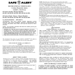
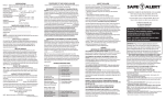
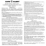
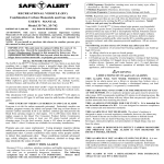
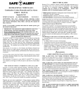
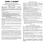
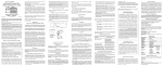
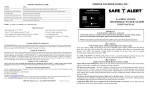
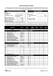
ABOUT THIS ALARM RECREATIONAL VEHICLE (RV) Combination Carbon Monoxide and Gas Alarm USER’S MANUAL 70 Series Models 70-742, 70-742-MS 70-742-R Kit, 70-742-R-MS Kit PATENT US 7,248,156 ALL RIGHTS RESERVED 70RV062009-6 ATTENTION: This user’s manual contains important Carbon Monoxide (CO) and gas alarm installation, operation, troubleshooting and warranty information. Read, follow, and keep this manual for future reference. NOTE: If you install or purchase this alarm for another person, give this manual to that person. IMPORTANT: This unit must be replaced within five years of its production date. Record the manufacture date in the section, Owner’s Replacement Record, in this manual for future use. The replacement date indicates the date beyond which the device may no longer detect carbon monoxide, propane or natural gas accurately. The device should be replaced. DUAL SENSOR TECHNOLOGY The SAFE-T-ALERT™ 70 Series combination CO / Gas Alarm is an alarm that combines into a single compact system, a powerful alarm that detects both Carbon Monoxide (CO) and explosive gases Propane (LPG) and Methane (Natural Gas). The 70 Series uses the latest microprocessor technology combined with two electronic self-cleaning sensors that operate independently of each other. The combined unit can detect both CO and explosive gases simultaneously. This detector is UL Listed as a CO Propane and Methane (Natural Gas) detector for RV use. Other explosive gases detected, but not tested by UL, include Acetone, Alcohol, Butane, and Gasoline all of which you may have in your RV. To prevent false alarms from brief “puffs” of gas the detector has a recheck cycle before alarming. If high levels of gas remain during the recheck cycle, the detector will alarm. The electronic CO sensor in your SAFE-T-ALERTTM CO alarm is very sensitive to CO gas. It will not react to most other gases. WHY EVERY RV NEEDS A 70 SERIES CO AND GAS ALARM Everyone is at risk for carbon monoxide poisoning! Particularly sensitive are children, pregnant women, the elderly and people with lung or heart disease or anemia! Carbon monoxide (CO) is an odorless, colorless gas that prevents the blood from carrying oxygen to vital organs. CO is 200 times more likely to replace oxygen in the blood. The Consumer Product Safety Commission (CPSC) recommends using at least one CO alarm located outside of sleeping areas. For the extra security, locate additional CO alarms in each sleeping area. Safe-T-Alert CO alarms are available for secondary installations. Propane gas can cause explosions! Using propane requires taking safety precautions to avoid injury. These gases are usually identified by an unpleasant odor. Certain conditions may make some people unable to detect this unpleasant odor. These conditions include advanced age, colds, allergies, and the use of tobacco, alcohol or drugs that may diminish the sense of smell. Because CO is a colorless, odorless, tasteless and highly poisonous gas; it can endanger lives even at low levels of concentration. The CO Alarm will alert you to potentially dangerous situations. The following symptoms may be related to CO POISONING. Discuss these symptoms with ALL household members and RV guests: Mild Exposure: Headaches, running nose, sore or watery eyes, often described as “flu-like” symptoms. Medium Exposure: Dizziness, drowsiness, vomiting. Extreme Exposure: Unconsciousness, brain damage and death. NOTE: Reported cases of CO gas poisoning indicate that while victims are aware they are not well, they are disoriented. They are unable to save themselves by exiting the RV or calling for assistance. Small children and pets may be affected first. Your SAFE-T-ALERTTM 70 Series alarm helps protect your household members and guests from CO produced while using your RV. CO gas is produced when any type of fuel is incompletely burned. Potential sources of CO in and around your RV can include gas or diesel engine exhaust, portable space heaters, gas stoves and ovens, furnaces, defective engine exhaust systems, portable grills, other nearby RVs, portable generators, generator exhaust, and other propane-powered appliances. All are sources of CO. The following are also sources of CO that may affect your RV: Extended operation of unvented fuel burning appliances can build up high CO levels. An idling vehicle in an open or closed garage. Temperature inversions can trap exhaust near the ground. CO build up can be caused by reverse/negative venting of fuel burning appliances including; 1) Clogged, loose or faulty stacks or chimneys of (clothes dryers, furnaces and water heaters, etc.), 2) wind direction and/or velocity, 3) simultaneous operation of multiple fuel burning appliances, and/or exhaust fans. ! WARNING: LIMITATIONS OF CO and GAS ALARMS THIS ALARM WILL NOT WORK WITHOUT POWER. Some reasons for no alarm power; are a blown or missing fuse, broken wire, a faulty wire connection or circuit breaker, a discharged battery, cut lead wires, or improper supply (+) or ground (-) connections. THIS ALARM WILL ONLY INDICATE THE PRESENCE OF GAS AT THE SENSOR. CO or explosive propane/natural gas gases may be present in other areas. MTI recommends installing CO alarms in all sleeping areas. Do not block or cover the alarm with any object that can prevent a gas leak or carbon monoxide from reaching the sensor. THIS ALARM IS INTENDED FOR USE IN RV's. It is intended for use inside the RV. It is not designed to measure compliance with commercial and industrial standards. THIS ALARM MAY NOT BE HEARD. The alarm’s loudness is designed to meet or exceed regulatory standards; however, the alarm may not be heard if alarms are located in remote locations or behind closed doors. Persons who are hard-of-hearing, have consumed alcoholic beverages, taken prescription, non-prescription or illegal drugs, may not hear the alarm. THIS ALARM IS DESIGNED TO DETECT CARBON MONOXIDE AND PROPANE GAS. THE ALARM IS NOT DESIGNED TO DETECT SMOKE, OR FIRE. THIS ALARM MAY NOT ALARM AT LOW CO LEVELS It is not designed to measure compliance with the Occupational Safety Health Administration (OSHA) commercial or industrial standards. Individuals with medical problems may consider using warning devices, which provide audible and visual signals for CO concentrations under 30 ppm. HOW TO PROTECT YOUR FAMILY CAUTION- The SAFE-T-ALERTTM 70 Series combination CO and Gas Alarm is designed to protect individuals from the acute effects of carbon monoxide exposure and gas leaks. It will not fully safeguard individuals with specific medical conditions. If in doubt, consult a medical practitioner. To protect your family, you should: ! WARNING ATTENTION: CCI CONTROLS GAS LEAK DETECTOR REPLACEMENT - DO NOT CONNECT ANY SAFE-TALERT alarm to non Safe-T-Alert supplied solenoids. You must use the new solenoid included in your Kit. The following diagrams provide additional alarm installation information: Bath Kitchen Figure Bedroom 1 Motorhome INSTALL THE ALARM PROPERLY. Carefully read and follow ALL the instructions in this manual. Test your unit every week. Alarms that do not work will not alert you to hazardous levels of CO or explosive gas. See the section, Test Procedure, in this manual for further information. MAKE REGULAR VISUAL INSPECTIONS. Check all fuel burning equipment including gas water-heaters, kitchen gas stoves, space heaters, gas dryers and all pilot lights. Check the color of the pilot flame. The color should be blue. MAKE REGULAR VISUAL INSPECTIONS OF THE ENGINE AND GENERATOR EXHAUST SYSTEMS. Cracked exhaust systems can allow CO to enter the living area. PROFESSIONALLY MAINTAIN YOUR ENGINE AND GENERATOR. Although gas engines and generators produce CO, a poorly tuned engine and generator will produce greater amounts CO. Recommended Alarm Location Figure 2 Kitchen Area Bedroom Living Area Travel Trailer If you smell unusual odors you may have a gas leak, immediately call a local propane gas supplier or fire department to check for possible leaks. WHERE TO INSTALL Install the 70 Series in the kitchen area near sources of a potential gas leaks. Some potential sources are a furnace, refrigerator, stove or oven. If potential sources of a gas leak are in separate areas, MTI recommends installing a gas alarm in each area. The NFPA and Consumer Product Safety Commission recommends installing a CO alarm outside the sleeping area. The 70 Series combination CO and gas alarm complies with that recommendation. INSTALL ALARM at least 4inches off the floor but no more than 20 inches off the floor. Recommended Alarm Location DO NOT INSTALL INSTALLATION INSTRUCTIONS Figure 3 Models 70-742 70-742-MS 70-742-R Kit 70-742-R-MS Kit ! WARNING Do not within Do not install withinMAY 12" of FAILURE TOinstall FOLLOW THESE INSTRUCTIONS RESULT of a door OR FAILURE a window that can open IN A 12" MALFUNCTION OF THE ALARM AND MAY VOID THE WARRANTY. SHOCK HAZARD: Turn off power before installing. Power Supply 12 VDC. WHERE NOT TO INSTALL 70 SERIES ALARMS DO NOT INSTALL behind furniture, drapes, in closets or areas that will block air flow to the alarm. DO NOT INSTALL within 12 inches (30cm) of opening windows, exterior doors, heating or return vents, or other drafty areas.. DO NOT INSTALL on an outside wall. DO NOT INSTALL on a wall switch controlled by a power line, ground fault circuit or to a circuit breaker. NOTE: Older RVs may have little or no insulation and therefore are draftier. Carefully consider mounting locations. Do not install Recommended Sizebehind 14 GA. TO 18 GA. Do NotWire install within 12" of vents Connect drapes the alarmortofurniture a properly fused circuit, maximum over protection device rating 15 amps. All connections must be in accordance with the National Electrical Code in the Unites Stated and the Canadian Electric Code in Canada . Connect to wiring or circuit that CANNOT be turned off by a switch or ground fault protector. Only use UL or recognized permanent wire connectors. It is acceptable to connect the 70 Series CO / LP gas alarm to the main disconnect. The alarm will be off along with all other 12 volt equipment when the main disconnect is turned to the off position. The RV must not be occupied when the main disconnect is in the off position. INSTALLATION INSTRUCTIONS Follow these instructions carefully. Failure to follow these instructions can damage the unit and void the warranty. Important: The 70 Series case requires 1 1/2” (38mm) clearance. MODEL 70-742 1. Basic Model 70-742 - Select a wall location between 4” and 20” off the floor. Cut a 5 5/8” (143mm) W x 3 1/8” (79mm) H hole. 2. Connect Supply (+) to the Red wire lead. Install a 1 amp fuse in the positive (+) circuit. Connect the Black wire to the 12 volt Ground (-). 3. Reconnect the power supply. Warm up 10 minutes then test the alarm. MODEL 70-742-MS 1. Model 70-742-MS Multi-station interconnect, (Maximum 10 units and 2000 feet of wire). Allows multiple 70-742-MS alarms to be connected together. When one of the alarms detects unsafe levels of CO or gas it will activate. It will also activate the audible alarm of all the interconnected units. Only the alarm that detected CO or gas will have its Red LED light lit up so that you can determine the cause of the alarm. Select a wall location no between 4” and 20” off the floor. Cut a 5 5/8” (143mm) W x 3 1/8” (79mm) H hole. 2. Connect the Red wire to the 12 volt supply (+). Install a 1 amp fuse in the positive circuit (+). Note you must use a separate 1 amp fuse for each alarm. Connect the Black wire to the 12 volt Ground (-). 3. Interconnect Wiring – Connect Blue wires from each alarm and Yellow wires for each alarm. Continue connecting in series (Daisy Chain). 4. Reconnect the power supply. Warm up 10 minutes then test the alarm. MODEL 70-742-R KIT 1. Model 70-742-R Kit - With Normally Closed relay. This unit supplies a relay with contacts rated 12 VDC, 3 amp (max). The relay is energized whenever the alarm is operational. It may be used to shut down a generator or to open an (optional) gas solenoid valve. The relay may also be used to interface to alarm systems, using either the normally closed or normally open contact, depending on the requirements of the alarm system. In the event of an alarm the relay will shut off. It will automatically energize after the unsafe levels of CO or explosive gas clears. Select a wall location between 4” and 20” off the floor. Cut a 5 5/8” (143mm) W x 3 1/8” (79mm) H hole. 2. Mount the solenoid according to its separate instructions. You must install the solenoid included with the 70-742-R Kit. Do not connect to an existing installed solenoid. SEE: SPECIAL WIRING NOTICE. Connect the Red wire and either White wire from the alarm to the 12 volt supply (+). Install a 5 amp fuse in the positive (+) circuit between this connection and the battery. Connect the Black wire to the 12 volt Ground (-). 3. Relay Output – Connect the remaining White wire from the alarm to either black wire from the solenoid. Ground the remaining Black wire from the solenoid to the negative side (-) of the 12 volt battery OR ground it to the RV Chassis. Note: Some devices do not require correct polarity and can be connected to either terminal or wire. 4. Reconnect the power supply. Warm up 10 minutes then test the alarm. MODEL 70-742-R-MS KIT 1. 2. 3. 4. 5. ! Model 70-742-R-MS Kit - With Normally Closed relay. This unit supplies a relay with contacts rated12 VDC, 3 amp (max). The relay is energized whenever the alarm is operational. It may be used to shut down a generator or to open an (optional) gas solenoid valve. The relay may also be used to interface to alarm systems, using either the normally closed or normally open contact, depending on the requirements of the alarm system. In the event of an alarm the relay will shut off. It will automatically energize after the unsafe levels of CO or gas clears. Select a wall location between 4” and 20” off the floor. Cut a 5 5/8” (143mm) W x 3 1/8” (79mm) H hole. Mount the solenoid according to its separate instructions. You must install the solenoid included with the 70-742-R-MS KIT. Do not connect to an existing installed solenoid. SEE: SPECIAL WIRING NOTICE. Connect the Red wire and either White wire from the alarm to the 12 volt supply (+). Install a 5 amp fuse in the positive (+) circuit between this connection and the battery. Note you must use a separate 5 amp fuse for each alarm. Connect the Black wire to the 12 volt Ground (-). Relay Output – Connect the remaining White wire from the alarm to either black wire from the solenoid. Ground the remaining Black wire from the solenoid to the negative side (-) of the 12 volt battery OR ground it to the RV Chassis. Note: Some devices do not require correct polarity and can be connected to either terminal or wire. Interconnect Wiring - Connect Blue wires from each alarm and Yellow wires from each alarm. Continue connecting in series (Daisy Chain). Reconnect the power supply. Warm up 10 minutes then test the alarm. DANAGER - FIRE RISK - CCI CONTROLS GAS LEAK DETECTOR REPLACEMENT - DO NOT CONNECT A SAFE-T-ALERT alarm to non Safe-T-Alert supplied solenoid. You must use the new solenoid included in your Kit. DO NOT CONNECT TO A CCI SOLENOID. Model 70-742-R-MS-KIT Wiring - Simultaneous CO and Gas Alarms— Because the risk of a propane gas explosion is generally a more serious danger, your alarm unit gives the gas alarm a higher priority during simultaneous alarm condition. If your unit generates alarms for both Gas and CO at the same time, the gas LED will flash red and the beeper will sound. The CO LED will be a solid Red until the CO is ventilated out of the RV, at which time the LED will return to the Green operational/safe color. Brownout Protection - The unit can tolerate short power interruptions and brownouts where the circuit voltage drops as low as 1 VDC. If the brownout lasts too long, the unit will reset and operate as described above. LOW POWER OPERATION This alarm will operate normally down to7 VDC. Do not operate this alarm below 7 VDC. VISUAL AND AUDIBLE ALARM SIGNALS SPECIAL WIRING NOTICE: When replacing CCI Controls LP Gas Leak Detectors they may have two power leads. Safe-T-Alert units only have one power lead. Simply connect the Safe-T-Alert power lead (Red) to the coach/house power supply and cap or remove the other power lead. DO NOT CONNECT BOTH POWER LEADS TO THE Safe-T-Alert ALARM – this will result in a dead chassis battery. Only use UL or recognized permanent wire connectors to replace any unit installed with spade connectors or wire nuts. TEST PROCEDURE ! WARNING TO REDUCE THE RISK OF CARBON MONOXIDE POISONING OR PROPANE GAS EXPLOSION, TEST THIS ALARM’S OPERATION AFTER THE RV HAS BEEN IN STORAGE, BEFORE EACH TRIP AND AT LEAST ONCE PER WEEK DURING USE BY PRESSING THE TEST/RESET BUTTON. ! WARNING WARNING: THE TEST BUTTON ONLY TESTS THE ALARM CIRCUIT NOT THE SENSORS. YOU MAY USE PROPANE OR BUTANE GAS TO TEST THE GAS SENSOR. Note it may take up to 10 seconds for the alarm to sound. TO TEST THE CO SENSOR USE A CAN OF SAFE-T-ALERT CO TEST GAS TO TEST THE 400 PPM CALABRATION POINT. DO NOT TRY TO GENERATE CO TO TEST THE ALARM. The TEST/RESET button tests all ELECTRICAL functions of the alarm. It does not check the sensor operation. The alarm may be tested at any time. The TEST/Mute switch is located on the front of the alarm. Press and hold the test button for 1 second IMPORTANT - If this alarm does not test properly return it immediately for repair or replacement. If the alarm is over five years old replace it. This SAFE-T-ALERTTM CO / Propane Gas Alarm is designed to be easyto-operate. The alarm has two indicator lights that display a specific color for each monitored condition. There also is a matching sound pattern for alarm conditions. CO ALARM The Red CO LED will flash and the alarm will sound 4 “BEEPS” then silent for 5 Seconds. These signals indicates that the CO level is over 70 ppm. IMMEDIATE ACTION IS REQUIRED. See Procedures To Take During An Alarm. This cycle will continue until the TEST/Mute button on the front of alarm is pressed. Ventilate the RV. The RED light will stay ON until the CO has cleared, or the alarm will reactivate in approximately 6 minutes if the CO is still present. DO NOT RE-ENTER THE RV. This alarm will return to normal operation after the RV s properly ventilated. PROPANE GAS ALARM The Red LED will Flash and the alarm will sound a steady tone whenever a dangerous level of propane or methane gas is detected. IMMEDIATE ACTION IS REQUIRED. See Procedures Take During A Gas Alarm The detector will continue to alarm until the Test/Mute switch on the front of the alarm is pressed. Ventilate the RV. The RED Gas LED will continue to flash until the gas has cleared, or the gas alarm will reactivate in approximately 5 minutes if the gas is still present. DO NOT RE-ENTER THE RV. This alarm will return to normal operation after the RV s properly ventilated. MALFUNCTION/SERVICE SIGNAL If any malfunction is detected, the Gas LED will remain off and the Operational/CO LED will alternate Red/Green and the alarm will sound once every 15 seconds. Press the Test/Mute button. If the Test/Mute button does not clear the signals, check the battery voltage. If the battery voltage is not low and the unit will not return to normal operation, immediately remove the alarm and return for service or warranty replacement. See the warranty section in this manual. OPERATION OPERATION When the unit is first powered up, the CO sensor requires a ten (10) minute initial warm-up period to clean the sensor element and achieve stabilization. The GREEN LED indicator will flash on and off during the 10 minute warm-up period. This unit cannot go into a alarm during the warm-up period. See Test Procedure in this manual. After the warm-up period, the GREEN power ON indicator should glow continuously If the ON indicator light does not light, see the section, Trouble-Shooting Guide, in this manual for further information. Do not attempt to fix it yourself. Gas Alarm: When you power the alarm, it has a warm-up period of approximately 1 minute. This unit cannot go into a gas alarm during the warm-up period. After 1 minute the alarm can detect explosive gas and will energize the relay on models 70-742-R Kit and 70-742-R-MS Kit. AUDIBLE SIGNAL NORMAL NONE 4 “BEEPS” 5 SECONDS OFF CO ALARM VISUAL SIGNAL STEADY GREEN STEADY RED 5 PROPANE ALARM “ CONSTANT FLASHING RED ALARM MALFUNCTION “ ALTERNATING RED/GREEN END OF LIFE SIGNAL BEEP” EVERY 25 SECONDS F A BEEPS EVERY 25-30 SECONDS RED RED GREEN GREEN FLASHING MEMORY FEATURE – This alarm has a Peak Level Memory feature that remembers the approximate amount of CO that activated it. The memory feature does not record brief exposure to CO that would not activate the alarm. This alarm will indicate one of four levels with chirps and blinks with the CO LED: To activate alarm level memory, press the TEST/RESET button for less than 1 second. 1 Chirp and 1 Green Blink = CO memory is clear 2 Chirps and 2 Red = below 100 ppm 3 Chirps and 3 Red Blinks = below 200 ppm 4 Chirps and 4 Red Blinks = above 200 ppm TROUBLE-SHOOTING GUIDE PROCEDURES TO TAKE DURING GAS ALARM 1. Turn off all Gas appliances (Stove, Heater, Furnace, Refrigerator, etc.), extinguish all flames and smoking material. 2. Press the Test/Mute switch. DO NOT DISCONNECT POWER 3. Evacuate the RV. Make sure everyone is accounted for. Leave the door and windows open. 4. Turn off the propane tank valve. 5. Determine and repair the source of the leak. Get professional help if necessary. CAUTION- DO NOT RE-ENTER UNTIL THE PROBLEM IS CORRECTED. Use this chart to trouble-shoot problems with this 70 Series Alarm. PROBLEM PROCEDURES TO TAKE DURING A CO ALARM IN THE USA CAUSE/SOLUTION Green Operational LED Off 1.Wire Connection 2. Reversed Wiring 3. Main Power Off 4. Missing or Blown Fuse 5. Contact Customer Service No Sound When Testing No Red LED When Testing Locked In Alarm Contact Customer Service Contact Customer Service Contact Customer Service MALFUNCTION ALARM LED Flashing Red/Green Beeps Every 25 Seconds 1. Check Battery Voltage Battery Voltage is Good and Alarm Will Not Reset 2. Contact Customer Service End of Life Signal LED Flashing RED RED GREEN GREEN Beeps Every 25 Seconds 1. Press Test/Reset Button to reset for 72 Hours. Can repeat for up to 30 Days 2. Replace Alarm HOW TO TAKE CARE OF YOUR ALARM This CO / Propane Gas Alarm is designed to be as maintenance free as possible. To keep your alarm in good working order, you must: TEST THE ALARM WEEKLY using the Test/Reset Button. See the section, Test Procedure, in this manual for further information. Test the Alarm every six months with Safe-T-Alert CO Test Gas and with a butane lighter. See Test Procedure Section. VACUUM THE DUST OFF THE ALARM COVER. At least once a year (more frequently in dusty locations), use the soft brush attachment from your vacuum to clean the alarm covers. CLEAN THE ALARM COVER WHEN DIRTY. Wash the alarm cover by hand. Use a cloth dampened in clean water. Dry with a soft cloth. DO NOT SPRAY CLEANING AGENTS OR WAXES DIRECTLY ONTO THE FRONT PANEL. This action may damage the sensor, cause an alarm or cause an alarm malfunction. OBSERVE THE COLOR OF THE INDICATOR LIGHT. At frequent intervals and during your weekly test, check the indicator light on the on the front panel of the alarm. See the section, Operation, in this manual for further information. PROCEDURES TO TAKE DURING AN ALARM Follow the alarm procedures for your country. The emergency number depends on your travel location. ! WARNING: Actuation of this device indicates the presence of carbon monoxide (CO) or propane gases, which can KILL YOU. If signal sounds (4 beeps and flashing or solid red light): 1) Operate the Test/Mute button; 2) Call your emergency local service (Phone Number _____________ ) (fire department or 911); 3) Immediately move to fresh air outdoors or by an open door/window. Check that all persons are accounted for. Do not reenter the premises or move away from the open door / window until the emergency responders have arrived, the premises have been aired out and your alarm remains in its normal operation. 4) After following steps 1-3, if your alarm reactivates within a 24-hour period, repeat steps 1-3 and call a qualified appliance technician. (Phone Number _______________) to investigate for sources of CO from fuel burning equipment and appliances, and inspect for proper operation of this equipment. If problems are identified during this inspection have the equipment serviced immediately. Note any combustion equipment not inspected by the technician and consult the manufacturers’ instructions, or contact the manufacturer directly, for more information about CO safety and this equipment. Make sure that the motor vehicles are not, and have not been, operating in an attached garage or adjacent to the residence. SPECIFICATIONS PROCEDURES TO TAKE DURING A CO ALARM IN CANADA ! WARNING: Actuation of this device indicates the presence of carbon monoxide (CO) and propane gases which can KILL YOU. If signal sounds (4 beeps and flashing or solid red light: 1) Operate the Test/Mute. Immediately move to fresh air - outdoors or by an open door/window. Check that all persons are accounted for. Do not reenter the premises or move away from the open door/window until the emergency responders have arrived, the premises have been aired out, and your alarm remains in its normal condition; 2) call your emergency local service (telephone number _________) ( Fire department or 911). WARRANTY RETURN PROCEDURES End of Life Signal – The Sensor has a 5 Year Service Life All 70 Series models include an End of Life (EOL) Signal indicating the sensor has reached the end of its service life and you must replace the alarm. The signal is the LED flashing RED RED GREEN GREEN with a beep every 25-30 seconds. The EOL Signal may be reset by pushing TEST / RESET button on the alarm. This will reset the EOL Signal for a period of 72 hours (3 days) for a total of up to 30 days. After 30 days the signal cannot be reset and the alarm must be replaced. DO NOT DISCONNECT THE ALARM UNTIL YOU HAVE A REPLACEMENT ALARM AVAILABLE TO INSTALL. It is MTI’s experience that a CO / Propane Gas Alarm is sounding for a reason. Call, ask your dealer to call, or e-mail our Customer Service Department (as listed below) to trouble shoot the situation. Customer Service Phone No. - 800-383-0269 Fax No. 847-546-9007 E-mail [email protected] Web Site: www.mtiindustries.com If Customer Service determines that the unit is defective, a Replacement Authorization (RA) number will be issued. No product will be accepted for service or replacement without first obtaining a RA number. MODELS 70-742, 70-742-MS, 70-742-R Kit, 70-742-R-MS Kit If authorized, return this product to: POWER SUPPLY 12 VDC NOMINAL CURRENT DRAW 108 mA (1.6 Amps with Solenoid Valve) OPERATIONAL TEMPERATURE -40 F to +150 F RELATIVE HUMIDITY 15% (+/- 5%) to 95% (+/- 4%) MTI Industries, Inc. Warranty Dept. RA # (INSERT RA NUMBER HERE) 31632 N. Ellis Drive Unit 301 Volo, IL 60073 AUDIBLE OUTPUT 85 dB @ 10 feet GAS ALARM TRIGGER GAS LEVEL CONFIRMATION < 25% of the LEL of Propane and Methane 8 Second delay before alarm CO ALARM TRIGGER 4 -15 Minutes @ 400 ppm CASE DIMENSIONS 6.5”W x 3.5”H x 1.38”D WARRANTY 1 Year Limited TESTING LABORATORY STANDARD Underwriters Laboratories UL 1484, Fourth Edition o o o o -40 C to +66 C UL 2034, Third Edition NOTE: Mark the RA number in the area shown on the outside of the box! NOTE: 70-742 is the basic unit (Single-station) with no interconnect, no relay, and no solenoid. 70-742-MS is the Multi-station unit with interconnect, no relay, and no solenoid. 70-742-R Kit is the basic unit (Single-station) with no interconnect, with a relay, and with a solenoid. 70-742-R-MS Kit is the Multi-station unit with interconnect, with a relay, and with a solenoid. OWNERS REPLACEMENT RECORD LIMITED PRODUCTS WARRANTY MTI INDUSTRIES, INC. warrants to the original retail purchaser that its products will be free from defects of material or workmanship for a period of One (1) year from the date of retail purchase. If proven to have been defective in original materials or workmanship and returned, delivery costs prepaid, MTI INDUSTRIES, INC. will replace this product free of charge. LIMITS OF WARRANTY Replacement is your exclusive remedy under this limited warranty or any other warranty (including any implied warranty of merchantability for a particular purpose). Any and all implied warranties or merchantability or fitness for a particular purpose shall be limited to the warranty period from the original date of retail purchase. MTI INDUSTRIES, INC., its dealers and distributors shall in no case be responsible or in any way liable for any incidental or consequential damages for any reason. Some states do not allow the limitation or exclusion of incidental or consequential damages, or allow limitations on how long an implied warranty lasts, so the above limitations may not apply to you. This warranty gives you specific rights, and you may also have other rights, which may vary, from state to state. PRODUCT NOT WARRANTED NOTE- There are no user serviceable parts inside the case. Opening any SAFE-T-ALERTTM product for any reason voids the warranty. This warranty does not cover damage or failure resulting from acts of God, abuse, misuse, neglect, or faulty installation. Replace this SAFE-T-ALERTTM 70 SERIES CO / GAS propane alarm within 5 years, of the production date on the back of the alarm. Production Date ______________________ Replace Date ______________________ Installer ________________________ NOTE: The replacement date indicates the date beyond which the device may no longer detect accurately. © MTI INDUSTRIES 2009