1
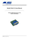
StickIt! Board V1.0 User Manual How to install and use your new StickIt! Board MAN002 (V1.0) Feb 4, 2012 XESS is disclosing this Document and Intellectual Property (hereinafter “the Design”) to you for use in the development of designs to operate on, or interface with XESS hardware devices. XESS expressly disclaims any liability arising out of the application or use of the Design. XESS reserves the right to make changes, at any time, to the Design as deemed desirable in the sole discretion of XESS. XESS assumes no obligation to correct any errors contained herein or to advise you of any correction if such be made. XESS will not assume any liability for the accuracy or correctness of any engineering or technical support or assistance provided to you in connection with the Design. THE DESIGN IS PROVIDED “AS IS” WITH ALL FAULTS, AND THE ENTIRE RISK AS TO ITS FUNCTION AND IMPLEMENTATION IS WITH YOU. YOU ACKNOWLEDGE AND AGREE THAT YOU HAVE NOT RELIED ON ANY ORAL OR WRITTEN INFORMATION OR ADVICE, WHETHER GIVEN BY XESS, OR ITS AGENTS OR EMPLOYEES. XESS MAKES NO OTHER WARRANTIES, WHETHER EXPRESS, IMPLIED, OR STATUTORY, REGARDING THE DESIGN, INCLUDING ANY WARRANTIES OF MERCHANTABILITY, FITNESS FOR A PARTICULAR PURPOSE, TITLE, AND NONINFRINGEMENT OF THIRD-PARTY RIGHTS. IN NO EVENT WILL XESS BE LIABLE FOR ANY CONSEQUENTIAL, INDIRECT, EXEMPLARY, SPECIAL, OR INCIDENTAL DAMAGES, INCLUDING ANY LOST DATA AND LOST PROFITS, ARISING FROM OR RELATING TO YOUR USE OF THE DESIGN, EVEN IF YOU HAVE BEEN ADVISED OF THE POSSIBILITY OF SUCH DAMAGES. THE TOTAL CUMULATIVE LIABILITY OF XESS IN CONNECTION WITH YOUR USE OF THE DESIGN, WHETHER IN CONTRACT OR TORT OR OTHERWISE, WILL IN NO EVENT EXCEED THE AMOUNT OF FEES PAID BY YOU TO XESS HEREUNDER FOR USE OF THE DESIGN. YOU ACKNOWLEDGE THAT THE FEES, IF ANY, REFLECT THE ALLOCATION OF RISK SET FORTH IN THIS AGREEMENT AND THAT XESS WOULD NOT MAKE AVAILABLE THE DESIGN TO YOU WITHOUT THESE LIMITATIONS OF LIABILITY. The Design is not designed or intended for use in the development of on-line control equipment in hazardous environments requiring failsafe controls, such as in the operation of nuclear facilities, aircraft navigation or communications systems, air traffic control, life support, or weapons systems (“High-Risk Applications”). XESS specifically disclaims any express or implied warranties of fitness for such High-Risk Applications. You represent that use of the Design in such High-Risk Applications is fully at your risk. © 2012 XESS, Inc. XESS, the XESS logo, and other designated brands included herein are trademarks of XESS Corporation. PMOD is a trademark of Digilent Inc. All other trademarks are the property of their respective owners. This document is licensed under the Attribution-ShareAlike 3.0 Unported license, available at http://creativecommons.org/licenses/by-sa/3.0/. MAN002 (V1.0) Feb 4, 2012 www.xess.com StickIt! Board V1.0 User Manual StickIt! Board V1.0 User Manual MAN002 (V1.0) February 4, 2012 The following table shows the revision history for this document. Date Version 01/15/12 1.0 Revision Initial release for StickIt! board V1.0. MAN002 (V1.0) Feb 4, 2012 www.xess.com StickIt! Board V1.0 User Manual Table of Contents Table of Contents C.1 Preliminaries........................................................................................................................... 1 Getting Help!................................................................................................................................ 1 Take Notice!................................................................................................................................. 1 Packing List.................................................................................................................................. 1 C.2 Setup....................................................................................................................................... 2 Inserting a XuLA Board into Your StickIt! Board.................................................................................2 Applying Power to Your StickIt! Board...............................................................................................3 Applying Power Through the USB Port..........................................................................................3 Applying Power Though the Power Jack........................................................................................4 Applying Power to Stand-Alone Applications..................................................................................5 C.3 Connections............................................................................................................................7 XuLA Board Socket........................................................................................................................7 Tautic TPLD Socket........................................................................................................................8 Voltage Regulators........................................................................................................................9 PMOD Connectors..........................................................................................................................9 Wing Connectors.........................................................................................................................11 C.4 Using Modules.......................................................................................................................12 A.1 I/O Locations........................................................................................................................14 A.2 Schematic..............................................................................................................................15 MAN002 (V1.0) Feb 4, 2012 www.xess.com StickIt! Board V1.0 User Manual C.1 Preliminaries Here's some helpful information before getting started. Getting Help! Here are some places to get help if you encounter problems: If you can't get the StickIt! board to work, send an e-mail message describing your problem to [email protected] or submit a problem report at http://www.xess.com/help.php. Our web site also has ● answers to frequently-asked-questions, ● example designs, application notes and tutorials, ● a forum where you can post questions. Take Notice! The XuLA Board is not 5V-tolerant. Do not connect 5V logic signals to the PMOD TM or Wing sockets of the StickIt! board. Only power the StickIt! board with a regulated 5 VDC, center-positive power supply. Packing List Here is what you should have received in your package: a StickIt! board. StickIt! Board V1.0 User Manual MAN002 (V1.0) Feb 4, 2012 www.xess.com 1 C.2 Setup The StickIt! board accepts a XuLA FPGA board and provides it with connections to separate StickIt! modules such as LED displays, buttons, audio I/O, etc. Inserting a XuLA Board into Your StickIt! Board You insert a XuLA board into the central row of sockets on the StickIt! board as shown below. Make sure XuLA prototyping header pins line-up with the sockets and that the USB connector is oriented towards the StickIt! board RESET button. USB Connector RESET Button To insure a stable connection with the StickIt! board, the XuLA board should have 0.25” square posts soldered into its prototyping header. The 0.19” round posts used for mounting a XuLA into a solderless breadboard should not be used or else intermittent connections will occur! StickIt! Board V1.0 User Manual MAN002 (V1.0) Feb 4, 2012 www.xess.com 2 Setup Applying Power to Your StickIt! Board There are several ways to power the combination of your XuLA and StickIt! board. Each of these will be discussed below. Applying Power Through the USB Port Connecting the XuLA Board to a USB port provides it with a 5V supply capable of delivering up to 500 mA of current. The 5V supply can also power the StickIt! board and any attached StickIt! modules by placing a shunt on the XULA-PWR jumper as shown below. XULA-PWR jumper with shunt StickIt! Board V1.0 User Manual MAN002 (V1.0) Feb 4, 2012 www.xess.com 3 Setup Applying Power Though the Power Jack For applications that require more power than the USB port can provide, you can attach a regulated, 5 VDC center-positive power adapter to the 5VDC jack on the StickIt! board. In this case, the shunt should be removed from the XULA-PWR jumper and placed on the 5V-PWR jumper on the StickIt! board as shown below. In this configuration, the USB port powers the XuLA board while the adapter powers the StickIt! board and any attached StickIt! modules. 5V-PWR jumper with shunt StickIt! Board V1.0 User Manual MAN002 (V1.0) Feb 4, 2012 www.xess.com 4 Setup Applying Power to Stand-Alone Applications For applications that operate stand-alone with no connection to a USB port, you can attach a regulated, 5 VDC center-positive power adapter to the 5VDC jack on the StickIt! board. In addition, shunts should be placed on both the XULA-PWR and 5V-PWR jumpers as shown below. This will transfer power from the adapter through the StickIt! board to the XuLA board. Shunts on XULA-PWR and 5V-PWR jumpers Leave the USB port unconnected A USB cable should not be attached to the XuLA board in this configuration or damage may result from the direct connection of the power adapter to the 5V supply pin of the USB port. StickIt! Board V1.0 User Manual MAN002 (V1.0) Feb 4, 2012 www.xess.com 5 Setup In order to prevent inadvertent damage, you can remove the 5V shunt on the XuLA board to disconnect the USB 5V supply as shown below. Note that doing this will prevent you from powering the XuLA through the USB port until the 5V shunt is restored. Open the 5V jumper on the XuLA board to protect the USB port StickIt! Board V1.0 User Manual MAN002 (V1.0) Feb 4, 2012 www.xess.com 6 C.3 Connections This chapter describes the various sections of the StickIt! board and shows how the XuLA board I/O connects to them. In addition to the partial schematics used below, you can find a complete schematic at the end of this manual. XuLA Board Socket The XuLA Board connects to the StickIt! board through the X1 socket. In addition, there are four more 20x1 socket strips (X2 - X5) adjacent to X1 that provide access to the XuLA board I/O after it is plugged into the StickIt! board. Please note the following: All the XuLA I/O channels (CHAN0 – CHAN31) and the channel clock (CHAN-CLK) are connected to the X2 – X5 sockets, but only 24 of these signals are then routed out to the PMOD and Wing sockets. (CHAN2, CHAN9, CHAN12, CHAN19, CHAN24, CHAN27, CHAN29, CHAN30 and CHAN31 do not connect to the PMOD and Wing sockets.) StickIt! Board V1.0 User Manual MAN002 (V1.0) Feb 4, 2012 www.xess.com 7 Connections The XuLA 5V pin is connected to the +5V-XULA signal on the StickIt! board. This allows the XuLA board to send power to or receive power from the StickIt! board. This is the only voltage supply shared by both the XuLa and StickIt! boards. The XuLA 3.3V pin is connected to the X4 socket, but it does not connect to the 3.3V supply of the StickIt! board (which connects to the X5 socket). The XuLA 1.2V pin is connected to the X4 and X5 sockets, but this voltage supply does not connect to anything else on the StickIt! board. The XuLA ground is connected to the StickIt! board ground. The reset pin of the XuLA board connects to the X4 and X5 sockets and also to the RESET pushbutton on the StickIt! board. Pushing this button resets the XuLa board. The analog I/O pins of the XuLA board connect to the X2 and X3 sockets but these signals do not connect to anything else on the StickIt! board. Tautic TPLD Socket As an alternative to using a XuLA board, there is an additional socket on the StickIt! board for holding a Tautic TPLB40 board with a 64-macrocell CPLD. StickIt! Board V1.0 User Manual MAN002 (V1.0) Feb 4, 2012 www.xess.com 8 Connections Voltage Regulators The StickIt! board accepts +5V from either the XuLa board (when there is a shunt on jumper XULA-PWR) or an external power supply (when there is a shunt on jumper 5VPWR). The StickIt! board voltage regulators create the additional +3.3V and +2.5V supplies. Be aware that placing shunts on both the XULA-PWR and 5V-PWR jumpers will connect the external power supply to the XuLA board power supply. This will cause damage unless 1) the USB cable is removed from the XuLA board, or 2) the 5V jumper on the XuLA board is open. (Note that in its factory-original configuration, the 5V jumper on the XuLA board is shorted by a wiring trace on the bottom of the PCB which must be cut to disconnect the 5V supply from the USB port.) PMOD Connectors There are six sockets for connecting external PMOD modules to the StickIt! board. StickIt! Board V1.0 User Manual MAN002 (V1.0) Feb 4, 2012 www.xess.com 9 Connections Five of these sockets (PM1 - PM6) accept either four-bit or eight-bit PMOD modules, while socket PM1 can be used only with four-bit modules. A total of 24 I/O signals connect from the XuLa board to the PMOD (and Wing) sockets, so you can use any combination of modules that require 24 total I/Os or less. For example, you could connect three eight-bit modules, or two eight-bit modules and two four-bit modules, or six four-bit modules, etc. Note that each PMOD socket shares four I/O lines with each of its adjacent PMOD sockets, so there must be an empty socket between any pair of eight-bit modules or else they will have I/O conflicts. For example, connecting eight-bit modules to sockets PM2, PM4 and PM6 is OK, but using PM2, PM3 and PM6 would cause a conflict between PM2 and PM3 on I/O lines CHAN3, CHAN18, CHAN1 and CHAN17. (Connecting a Wing module will also consume I/O resources and may cause additional conflicts.) Each PMOD socket has an associated jumper to connect either the 3.3V or 5V power supply to the attached module. In their factory-original configuration, each of these jumpers is set to 3.3V by a shorting trace on the bottom of the StickIt! board PCB. You must cut this trace and install a jumper and shunt if you want to use a 5V module. StickIt! Board V1.0 User Manual MAN002 (V1.0) Feb 4, 2012 www.xess.com 10 Connections Wing Connectors There are three sockets for connecting external eight-bit Wing modules to the StickIt! board. The Wing sockets are placed end-to-end so you can also use a 16- or 24-bit Wing module (if such a thing exists). A total of 24 I/O signals connect from the XuLa board to the Wing sockets, so you can use any combination of modules that require 24 total I/Os or less. For example, you could connect three eight-bit modules, or one eight-bit module and a 16-bit module. Unlike the PMOD sockets, there are no I/O lines shared between the Wing sockets. However, the Wing sockets do share the same I/O lines used by the PMOD sockets, so there can be conflicts depending upon which PMOD and Wing sockets are used in an application. Each Wing socket connects to the 5V, 3.3V and 2.5V supplies on the StickIt! board, so there is no need for a jumper to select which supply powers the attached Wing module. StickIt! Board V1.0 User Manual MAN002 (V1.0) Feb 4, 2012 www.xess.com 11 C.4 Using Modules Using a PMOD or Wing module with the StickIt! board is easy. Just do the following: Attach the module to either a PMOD or Wing socket on the StickIt! board. Determine the channel signals on the PMOD or Wing socket that connect to each I/O of the module. Find which FPGA pin of the XuLA board connects to each channel signal. Make a UCF file associating each FPGA pin with each I/O of the module. Include the UCF file in your Xilinx ISE FPGA project. As an example, consider a simple eight-bit Wing module with eight LEDs, each connected to one of the I/O signals like so: StickIt! Board V1.0 User Manual MAN002 (V1.0) Feb 4, 2012 www.xess.com 12 Using Modules If this module is attached to the Wing socket WING1, then the channel connections are: LED1 LED2 LED3 LED4 LED5 LED6 LED7 LED8 CHAN15 CHAN-CLK CHAN16 CHAN0 CHAN17 CHAN1 CHAN18 CHAN3 Assuming a XuLA-200 board is plugged into the StickIt! board, then the FPGA pins connected to these channels are (from the XuLA manual): CHAN15 CHAN-CLK CHAN16 CHAN0 CHAN17 CHAN1 CHAN18 CHAN3 p35 p44 p34 p36 p33 p37 p32 p50 From this, you can make the following pin assignments in a UCF file: NET NET NET NET NET NET NET NET led1 led2 led3 led4 led5 led6 led7 led8 LOC LOC LOC LOC LOC LOC LOC LOC = = = = = = = = p35; p44; p34; p36; p33; p37; p32; p50; # # # # # # # # CHAN15 CHAN-CLK CHAN16 CHAN0 CHAN17 CHAN1 CHAN18 CHAN3 Then include this UCF file in your ISE project. StickIt! Board V1.0 User Manual MAN002 (V1.0) Feb 4, 2012 www.xess.com 13 A.1 I/O Locations The connections of the XuLA board I/O channels to the PMOD and Wing sockets of the StickIt! board are shown below. StickIt! Board V1.0 User Manual MAN002 (V1.0) Feb 4, 2012 www.xess.com 14 A.2 Schematic StickIt! Board V1.0 User Manual MAN002 (V1.0) Feb 4, 2012 www.xess.com 15