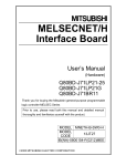
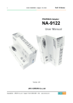
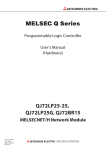
1
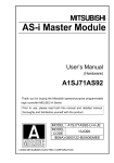
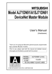
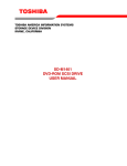
CAUTION
Data link module
type A1SJ71AP21(-S3)
/AR21
User’s Manual
(Hardware)
A1SJ71AP21
A1SJ71AP21-S3
A1SJ71AR21
Thank you for purchasing the Mitsubishi program logic controller
MELSEC-A series.
Prior to use, please read this and relevant manuals thorougly
to fully understand the product.
MODEL
A1SJ71AP21/R21
(H/W)-U-E
MODEL
13JE58
CODE
IB(NA)-66480-B(0602)MEE
1994 MITSUBISHI ELECTRIC CORPORATION
SAFETY PRECAUTIONS
(Be sure to read these instructions before use.)
Before using this product, please read this manual and the relevant
manuals introduced in this manual carefully and pay full attention to
safety to handle the product correctly.
The instructions given in this manual are concerned with this product.
For the safety instructions of the programmable controller system,
please read the CPU module user's manual.
In this manual, the safety instructions are ranked as "DANGER" and
"CAUTION".
DANGER
Indicates that incorrect handling may cause hazardous
conditions, resulting in death or severe injury.
CAUTION
Indicates that incorrect handling may cause hazardous
conditions, resulting in medium or slight personal injury
or physical damage.
CAUTION level may lead to a serious consequence
Note that the
according to the circumstances.
Always follow the instructions of both levels because they are important
to personal safety.
Please save this manual to make it accessible when required and
always forward it to the end user.
[Design Precautions]
DANGER
Refer to the type MELSECNET, MELSECNET/B Data Link System
Reference Manual for each station’s operating status when a
communication error occurs in the network.
Erroneous operation may result in accidents.
When controlling a running PLC (data modification) by connecting a
peripheral device or GX Developer to a CPU module or by connecting a
PC to a special function module, create an interlock circuit in the
sequence program so that the entire system will function safely all the
time.
Also, before performing any other controls (e.g. program modification,
operating status change (status control)), read the relevant manual(s)
carefully to ensure the safety.
Especially in control from an external device to a PLC in a remote
location, some PLC side problem may not be resolved immediately due
to failure of data communications.
To prevent this, create an interlock circuit in the sequence program and
set up corrective procedures to be taken in the event of communication
failure between the external device and PLC CPU.
Do not bundle the control wires and communication cables with the main
circuit or power wires, or install them close to each other. They should be
installed at least 100mm (3.94in.) away from each other. Failure to do so
may generate noise that may cause malfunctions.
[Installation Precautions]
CAUTION
Use the PLC in the operating environment that meets the general
specifications of this manual.
Using the PLC in any other operating environments may cause electric
shocks, fires or malfunctions, or may damage or degrade the product.
Insert the module fixing projection into the fixing hole in the base unit to
press the module using the hole as the fulcrum, and then tighten the fixing
screw with the specified torque.
When no screw is tightened, even if the module is installed correctly, it may
cause malfunctions, a failure or a drop of the module.
Tighten the screws within the range of specified torque. If the screws are
loose, it may cause the module to fallout, short circuits, or malfunction. If the
screws are tightened too much, it may cause damage to the screw and/or
the module, resulting in fall out, short circuits or malfunction.
Completely turn off the externally supplied power used in the system before
mounting or removing the module. Failure to do so may damage the
product.
Do not directly touch the conducting parts and electronic parts of the
module. This may cause the module to malfunction or fail.
[Wiring Precautions]
DANGER
Completely turn off the externally supplied power used in the system when
installing or placing wiring.
Failure to do so may cause electric shocks or damage the product.
CAUTION
Solder coaxial cable connectors properly. Incomplete soldering may result in
malfunctioning.
Be careful not to let foreign particles such as chaff and wire chips get inside
the module. They may cause a fire, mechanical breakdown or malfunction.
The top surface of the module is covered with a protective film to prevent
foreign objects such as wire chips from entering the module during wiring
work. Do not remove this film until all the wiring work is complete. Before
operating the system, be sure to remove the film to provide adequate heat
ventilation.
Make sure to place the communication and power cables to be connected to
the module in a duct or fasten them using a clamp. If the cables are not
placed in a duct or fastened with a clamp, their positions may become
unstable and may move, or they may be pulled inadvertently. This may
damage the module and the cables or cause the module to malfunction
because of faulty cable connections.
[Setup and Maintenance Precautions]
CAUTION
Please read this manual thoroughly and confirm the safety before starting
online operations (especially, program modifications, forced outputs, and
operating status modifications), which are performed by connecting the GX
Developer via the MELSECNET network system to a running CPU module
of other station. Performing incorrect online operations may damage the
machinery or result in accidents.
Never disassemble or modify the module. This may cause breakdowns,
malfunctions, injuries or fire.
Use any radio communication device such as a cellular phone or a PHS
phone more than 25cm (9.85 inch) away in all directions of the PLC.
Not doing so can cause a malfunction.
Shut off all phases of the external power supply in the system before
mounting or dismounting the module. Failure to do so may cause failure or
malfunction of the module.
Do not touch the terminals while the power is on. Doing so may cause
malfunctions.
Shut off all phases of the external power supply in the system before
cleaning or retightening the terminal screws or module fixing screws.
Not doing so may cause failure or malfunction of the module.
If the screws are loose, it may cause the module to fallout, short circuits, or
malfunction.
If the screws are tightened too much, it may cause damages to the screws
and or/the module, resulting in fall out, short circuits or malfunction.
Before touching the module, be sure to touch grounded metal, etc. to
discharge static electricity from human body, etc.
Failure to do so may cause the module to fail or malfunction.
[Disposal Precautions]
CAUTION
When disposing of this product, treat it as industrial waste.
2. Specification
Manuals
The following manual is related with this product.
Please order it as necessary.
Item
Related Manuals
Manual name
Manual Number
(Model code)
type MELSECNET, MELSECNET/B Data Link
System Reference Manual
IB-66350
(13JF70)
Please read type MELSECNET, MELSECNET/B Data Link System
Reference Manual before using this module
Compliance with the EMC Directive and the Low Voltage Directive
When incorporating the Mitsubishi PLC into other industrial machinery or
equipment and keeping compliance with the EMC and low voltage
directives, refer to Chapter 3 "EMC Directive and Low Voltage
Instruction" of the User’s Manual (Hardware) for the CPU module used
or the PLC CPU supplied with the base unit.
The CE logo is printed on the rating plate of the PLC, indicating
compliance with the EMC and low voltage directives.
For making this product compliant with the EMC and low voltage
directives, please refer to Section 3.1.3 "Cable" in Chapter 3 of the
above-mentioned user’s manual.
1. Overview
This manual provides the specifications and descriptions of the part names
of the A1SJ71AP21(-S3)/AR21 Data Link Module (hereinafter referred to
as A1SJ71AP21/AR21) used in the MELSEC-A series MELSECNET data
link system.
(1) The following shows applications, applicable cable types and mounting
positions of the A1SJ71AP21/AR21.
Applicable cable
Optical fiber
Application
cable
Coaxial
cable
SI,
GI
H-PCF
A1SJ71AP21
---
A1SJ71AP21-S3
Master or
local station
A1SJ71AR21
-----
---
Module mounting
position
---
I/O slot in A1S series main
base or extension base
---
A1SJ71AR21 cannot
be mounted in slot 0
of A1S6 B extension
base.
(2) After unpacking, confirm that the following is included.
Product name
A1SJ71AP21 data link module
Quantity
1
Product name
A1SJ71AP21-S3 data link module
Quantity
1
• A1SJ71AR21
Product name
A1SJ71AR21 data link module
Quantity
1
(3) The following table lists PLC CPUs applicable to the A1SJ71AP21/
AR21 and numbers of mountable modules.
Applicable PLC CPU
Error control system
RAS function
Connector
Transmission loss
Sending level
Receiving level
• A1SJ71AP21-S3
No. of Mountable Modules
A1SCPU, A1SJCPU-S3, A2SCPU, A1SHCPU,
A1SJHCPU, A2SHCPU
1
A2ASCPU(S1), A2USHCPU-S1, Q2ASCPU(S1),
Q2ASHCPU(S1)
2
Coaxial Cable
Data Link
A1SJ71AR21
Model
A1SJ71AP21 A1SJ71AP21-S3
Max. number
Input (X)
of link points
Up to the max. I/O points for the CPU used
used per
Output (Y)
station
Max.
B
1024points (128bytes)
number of
link points
MELSECNET per system W
1024points (2048bytes)
Mode
Max. number
Y(points)+B(points)
of link points
+ 2 W(points) 1024bytes
8
per station
Max.
B
4096points (512bytes)
number of
link points
4096points (8192bytes)
per system W
MELSECNET
first half:
II Mode
Y(points)+B(points)
Max. number
+ 2 W(points) 1024bytes
of link points
8
per station
B(points)
second half:
+ 2 W(points) 1024bytes
8
Max.
B
4096points (512bytes)
number of
link points
4096points (8192bytes)
per system W
MELSECNET
first half:
II Composite
Y(points)+B(points)
Mode
Max. number
+ 2 W(points) 1024bytes
of link points
8
per station
B(points)
second half:
+ 2 W(points) 1024bytes
8
Internal current consumption
0.33A
0.80A
(5V DC)
Weight
0.30kg
0.33kg
No. of occupied I/O points
32points
System's allowable
Within 20ms
momentary power failure time
Communication speed
1.25Mbps
Communications method
Half-duplex bit serial
Synchronous method
Frame synchronous
Transmission path method
Duplex loop
Max. 10km
Max. 10km
Max. 10km
(32810ft)
(32810ft)
(32810ft)
Overall loop distance
(1km (3281 ft)
(2km (6562ft) (500m (1640.5ft)
station intervals) station intervals) station intervals)
Number of connectable
Max. 65 stations/loop (1 master station, 64
stations
local/remote I/O stations)
Demodulation method
CMI
Transmission format
Conforms to HDLC (frame method)
Cable used
• A1SJ71AP21
Fiber-Optic Cable Data Link
Retry due to CRC (generating polynomial X16
+ X12 + X5 + 1) and time over
The loopback function checks error detection and
cable breakage.
The diagnostic function checks the self link line
2-core optical connector plug
--(Arranged by user*1)
SI optical fiber
GI optical fiber
3C-2V, 5C-2V
cable
H-PCF optical
cable
equivalent
fiber cable
Max. 12dB/km
Max. 3dB/km
---17 to -11 dBm -17 to -10 dBm
--(peak value)
(peak value)
-32 to -11 dBm -29 to -10 dBm
--(peak value)
(peak value)
*1: Specialised skill and specific tools are required to connect the connector to
the opticalfiber cable; the connector itself is a custom product. Please
contact your nearest Mitsubishi Electric System & Service Corporation
when purchasing these products.
REMARK
1) The overall loop distance refers to the
distance from the master station sending
port to the master station receiving port
via slave stations.
For both the fiber optic cables and coaxial
cables, The overall loop distance is a
maximum of 10km (32810ft.).
2) For general specifications of the date link
system, refer to the user's manual for the
PLC CPU module that is to be used.
M
L1
R2
L6
R5
L3
R4
Overall distance
3. Names and Settings of Each Part
A1SJ71AP21(-S3)
4. Mounting and Installation
A1SJ71AR21
A1SJ71AR21
A1SJ71AP21
1)
2)
RUN
SD
RD
F.LOOP
CPU
CRC
OVER
AB.IF
TIME
DATA
UNDER
F.LOOP
R.LOOP
E
R
R
O
R
X10
STATION
NO.
X1
1)
2)
E
R
R
O
R
0:ONLINE(A.R.)
1:ONLINE(U.R.)
2:OFFLINE
3:TEST 1(F.L.)
4:TEST 2(R.L.)
5:TEST 3(B.M.)
6:TEST 4(B.S.)
7:TEST 5(S.R.)
3)
X10
X1
0:ONLINE(A.R.)
1:ONLINE(U.R.)
2:OFFLINE
3:TEST 1(F.L.)
4:TEST 2(R.L.)
5:TEST 3(B.M.)
6:TEST 4(B.S.)
7:TEST 5(S.R.)
FRONT SIDE
FRONT SIDE
R-SD
IN
IN
F-RD
F-SD
OUT
OUT
R-RD
A1SJ71AR21
A1SJ71AP21
5)
4)
No.
1) LED
Name
A1SJ71AP21
RUN
SD
RD
F.LOOP
CPU
CRC
OVER
AB.IF
TIME
DATA
UNDER
F.LOOP
R.LOOP
E
R
R
O
R
2) Station number setting
switches
X10
STATION
NO.
X1
3) Mode setting switch
MODE
0:ONLINE(A.R.)
1:ONLINE(U.R.)
2:OFFLINE
3:TEST 1(F.L.)
4:TEST 2(R.L.)
5:TEST 3(B.M.)
6:TEST 4(B.S.)
7:TEST 5(S.R.)
4) Connector
OUT
IN
Forward loop
sending
Reverse loop
receiving
Reverse loop
sending
Forward loop
receiving
5) Connector
OUT R-RD
Reverse loop
receiving
OUT F-SD
Forward loop
sending
This section describes the handling precautions for procedures from
unpacking to installation of the A1SJ71AP21/AR21 and its installation
environment.
For details, refer to the user’s manual for your PLC CPU.
STATION
NO.
MODE
MODE
3)
CRC
OVER
AB.IF
TIME
DATA
UNDER
F.LOOP
R.LOOP
RUN
SD
RD
F.LOOP
CPU
Description
ON when data link is normal
ON during data transmission
ON during data reception
• ON while data are received from the
forward loop side
• OFF while data are received from the
reverse loop side
CPU
ON during communication with PLC CPU
CRC
ON during code check of received data
OVER
ON indicating an error when receive data
processing is delayed
AB.IF
ON indicating an error when too many
consecutive 1s are received or when the
length of received data is too short
TIME
ON indicating an error when the data link
monitoring timer is activated
DATA
ON indicating an error when erroneous data
of 2k bytes or more are received
UNDER ON indicating an error when the internal
processing of send data is not done at the
fixed intervals
F.LOOP Turns ON by a reception error on the
forward loop side
R.LOOP Turns ON by a reception error on the
reverse loop side
Set a station number within a range from 00 to 64.
(factory set: 00)
• master station 00
local station
01 to 64
X10
Set a tens digit.
X1
Set a units digit.
RUN
SD
RD
F.LOOP
Select a mode from the following. (factory set: 00)
No.
Mode
Description
0 On-line
Data link with automatic return
1 On-line
Data link without automatic return
2 Off-line
Puts this station into cut-off status.
3 Forward
Checks the forward loop in the
loop test
entire data link system.
4 Reverse
Checks the reverse loop in the
loop test
entire data link system.
5,6 Station-to- Checks a line between 2 adjacent
station test stations.
7 SelfChecks hardware of the data link
loopback
module, including sending/
test
receiving circuits in the
communication system.
8 to F
--Use prohibited
For A1SJ71AP21(-S3)
Optical fiber cable connector
4.1 Handling Precautions
In this section, handling precautions for the module are described.
(1) The module case is made of resin, so do not drop it or apply strong
impacts on it.
(2) Do not remove the PC board from the module case. This may cause
a fault.
(3) Be careful to prevent foreign matter from entering from the module
top during wiring.
(4) Tighten the module fixing screws within the following ranges.
Screw location
Module fixing screws (M4 screw)
4.2 Installation Environment
Do not install PLCs in the following environments:
(1) Locations where the ambient temperature is outside the range 0 to
55 .
(2) Locations where the ambient humidity is outside the range 10% RH
to 90%RH.
(3) Locations where dewing occurs due to sudden temperature changes.
(4) Locations exposed to corrosive or combustible gases.
(5) Locations exposed to large amounts of highly conductive dust, iron
powder, oil mist, salt or organic solvents.
(6) Locations where the module is exposed to direct sunlight.
(7) Locations where a strong electric or magnetic field is generated.
(8) Locations where the module will be subject to direct vibration or
impact.
5. Cable Connection
5.1 Connecting optical fiber cables
FRONT
OUT IN
FRONT
OUT IN
IN R-SD
Reverse loop
sending
IN F-RD
Forward loop
receiving
POINT
For details on the settings and the operating method in test mode, refer
to the type MELSECNET, MELSECNET/B Data Link System Reference
Manual.
FRONT
OUT IN
FRONT
IN
OUT
Master station
IN : Connected to previous station's OUT
OUT: Connected to next station's IN
No.2
No.1
5.2 Connecting coaxial cables
FRONT
OUT
IN
OUT
IN
OUT
IN
R-RD
F-RD
F-RD
F-RD
FRONT R-RD
FRONT R-RD
FRONT
F-SD
R-SD
F-SD
R-SD
F-SD
R-SD
IN
OUT
R-SD
F-RD
F-SD
R-RD
IN
Master station
For A1SJ71AR21
Coaxial cable connector
Torque range
78 to 118N.cm
No.1
No.2
R-SD: Connected to previous
station's OUT R-RD
IN F-RD: Connected to previous
station's OUT F-SD
OUT F-SD: Connected to next
station's IN F-RD
OUT R-RD: Connected to next
station's IN R-SD
5.3 Securing space for the cables
The radius of the fiber-optic cables or coaxial cables must not be smaller
than the allowable bend radius.
When connecting a fiber-optic cable or coaxial cable to a link module,
make sure that there is enough space for the cable to be bent to a larger
radius than the allowable bend radius.
For connector A and bend radius r of the fiber-optic cable, contact
Mitsubishi Electric System & Service Corporation.
Data link
module
Cable
A
r
Coaxial
cable
Connector
A (mm)
3C-2V
Allowable Bend
Radius r (mm)
23
30
5C-2V
30
6. External Dimensions
A1SJ71AP21(-S3)
A1SJ71AP21
CRC
OVER
AB.IF
TIME
DATA
UNDER
F.LOOP
R.LOOP
RUN
SD
RD
F.LOOP
CPU
E
R
R
O
R
X10
STATION
NO.
X1
130
(5.12)
MODE
0:ONLINE(A.R.)
1:ONLINE(U.R.)
2:OFFLINE
3:TEST 1(F.L.)
4:TEST 2(R.L.)
5:TEST 3(B.M.)
6:TEST 4(B.S.)
7:TEST 5(S.R.)
FRONT SIDE
5 (0.20)
IN
OUT
*1
A1SJ71AP21
6.5
(0.26)
34.5
(1.36)
93.6
(3.69)
A1SJ71AR21
A1SJ71AR21
CRC
RUN
E
R
R
O
R
OVER
AB.IF
SD
RD
TIME
F.LOOP
DATA
UNDER
CPU
F.LOOP
R.LOOP
X10
STATION
NO.
X1
130
(5.12)
MODE
0:ONLINE(A.R.)
1:ONLINE(U.R.)
2:OFFLINE
3:TEST 1(F.L.)
4:TEST 2(R.L.)
5:TEST 3(B.M.)
6:TEST 4(B.S.)
7:TEST 5(S.R.)
FRONT SIDE
R-SD
IN
7 (0.28)
F-RD
F-SD
OUT
R-RD
30
(1.18)
A1SJ71AR21
6.5
(0.26)
93.6
(3.69)
34.5
(1.36)
Unit: mm (inch)
*1: Please contact your nearest Mitsubishi Electric System & Service
Corporation for detail.
Warranty
Mitsubishi will not be held liable for damage caused by factors found not to be
the cause of Mitsubishi; machine damage or lost profits caused by faults in the
Mitsubishi products; damage, secondary damage, accident compensation
caused by special factors unpredictable by Mitsubishi; damages to products
other than Mitsubishi products; and to other duties.
For safe use
y This product has been manufactured as a general-purpose part for general
industries, and has not been designed or manufactured to be incorporated in a
device or system used in purposes related to human life.
y Before using the product for special purposes such as nuclear power, electric
power, aerospace, medicine or passenger movement vehicles, consult with
Mitsubishi.
y This product has been manufactured under strict quality control. However,
when installing the product where major accidents or losses could occur if the
product fails, install appropriate backup or failsafe functions in the system.
Country/Region Sales office/Tel
U.S.A
Mitsubishi Electric Automation Inc.
500 Corporate Woods Parkway Vernon
Hills, IL 60061
Tel : +1-847-478-2100
Brazil
MELCO-TEC Rep. Com.e Assessoria
Tecnica Ltda.
Rua Correia Dias, 184,
Edificio Paraiso Trade Center-8 andar
Paraiso, Sao Paulo, SP Brazil
Tel : +55-11-5908-8331
Germany
Mitsubishi Electric Europe B.V. German
Branch
Gothaer Strasse 8 D-40880 Ratingen,
GERMANY
Tel : +49-2102-486-0
U.K
Mitsubishi Electric Europe B.V. UK
Branch
Travellers Lane, Hatfield, Herts., AL10
8XB,UK
Tel : +44-1707-276100
Italy
Mitsubishi Electric Europe B.V. Italian
Branch
Centro Dir. Colleoni, Pal. Perseo-Ingr.2
Via Paracelso 12, 20041 Agrate B.,
Milano, Italy
Tel : +39-039-6053344
Spain
Mitsubishi Electric Europe B.V. Spanish
Branch
Carretera de Rubi 76-80
08190 Sant Cugat del Valles,
Barcelona, Spain
Tel : +34-93-565-3131
France
Mitsubishi Electric Europe B.V. French
Branch
25 Boulevard des Bouvets, F-92741
Nanterre Cedex, France
TEL: +33-1-5568-5568
South Africa
Circuit Breaker Industries LTD.
Tripswitch Drive, Elandsfontein Gauteng,
South Africa
Tel : +27-11-928-2000
Country/Region Sales office/Tel
Hong Kong
Ryoden Automation Ltd.
10th Floor, Manulife Tower, 169 Electric
Road, North Point, HongKong
Tel : +852-2887-8870
China
Ryoden Automation Shanghai Ltd.
3F Block5 Building Automation
Instrumentation Plaza 103 Cao Bao Rd.
Shanghai 200233 China
Tel : +86-21-6120-0808
Taiwan
Setsuyo Enterprise Co., Ltd.
6F., No.105 Wu-Kung 3rd.RD, Wu-Ku
Hsiang, Taipei Hsine, Taiwan
Tel : +886-2-2299-2499
Korea
HAN NEUNG TECHNO CO.,LTD.
1F Dong Seo Game Channel Bldg.,
660-11, Deungchon-dong Kangsec-ku,
Seoul, Korea
Tel : +82-2-3660-9552
Singapore
Mitsubishi Electric Asia Pte, Ltd.
307 Alexandra Road #05-01/02,
Mitsubishi Electric Building
Singapore 159943
Tel : +65-6473-2308
Thailand
F. A. Tech Co.,Ltd.
898/28,29,30 S.V.City Building,Office
Tower 2,Floor 17-18 Rama 3 Road,
Bangkpongpang, Yannawa,
Bangkok 10120
Tel : +66-2-682-6522
Indonesia
P.T. Autoteknindo SUMBER MAKMUR
Jl. Muara Karang Selatan Block a Utara
No.1 Kav. No.11 Kawasan Industri/
Pergudangan Jakarta - Utara 14440
Tel : +62-21-663-0833
India
Messung Systems Put,Ltd.
Electronic Sadan NO:111 Unit No15,
M.I.D.C BHOSARI,PUNE-411026, India
Tel : +91-20-712-2807
Australia
Mitsubishi Electric Australia Pty. Ltd.
348 Victoria Road, PostalBag, No 2,
Rydalmere, N.S.W 2116, Australia
Tel : +61-2-9684-7777
HEAD OFFICE : TOKYO BUILDING, 2-7-3 MARUNOUCHI, CHIYODA-KU, TOKYO 100-8310, JAPAN
NAGOYA WORKS : 1-14, YADA-MINAMI 5-CHOME, HIGASHI-KU, NAGOYA, JAPAN
When exported from Japan, this manual does not require application to the Ministry
of Economy, Trade and Industry for service transaction permission.
Specifications subject to change without notice.
Printed in Japan on recycled paper.