1
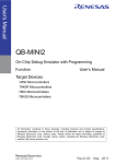
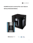
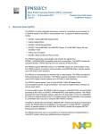
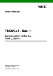
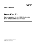
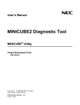
SBA1-070096-01
B5D
FA-B series User’s manual
FA-B series are the programming adapters for NEC Flash memory micro controllers. This line needs to be wired
by customer. And support the following Flash programmers.
FL-PR5, FL-PR4 ----------------------- Products of ASMIS
PG-FP5, PG-FP4, QB-MINI2 ------- Products of NEC Electronics
Also, the following adapter product is available.
FA-RX series
Specialized adapter for the specific micro controllers (Wired already)
Procedure
1. For programming, please wire the required wiring at first.
Wire the required signals of programmer-side terminals P2 (SI, SO, SCK, X1, X2, /RESET, VPP, H/S, FLMD0,
FLMD1), clock terminals (X1, X2), power supply terminals (VDD, VDD2, GND) and micro-controller-side terminals
SP (the periphery of the IC socket). Please wire by using PVC wire by means of soldering.
For wiring, please follow the wiring specifications such as the user’s manual of the micro controller, etc.
Programmer-side terminals P2
Note1. VDD wiring for the clock circuit (VDD-ICVDD)
RESET VDD VPP H/S -- FLMD1 FLMD0 -2
1
ICVDD
16
15
GND SI SO SCK CLK VDD2 -- --
Clock terminals X1, X2
Note 1, 2
IC socket
Power supply terminals
VDD, VDD2, GND
Micro controller-side
terminals SP
Pin-number of the micro controller
1 4 5 8
9 12 13
2 3 6 7 1 0 11 1 4
This example shows the wiring
Universal area
between SCK of programmer and
Note. Pin-position depends on the
FA products.
14th-pin of micro controller. For
practical wirings, please refer to
the user’s manual of the micro
controllers, or etc.
1/4
SBA1-070096-01
B5D
[Notes]
Note 1. For FA-B series board, the following clock circuit is mounted. If the reversed X1, X2 signals are
required, these X1, X2 terminals should be wired. (TC7WU04 is put to use, which is equal in quality to
74HCU04.)
Power supply (ICVDD) of IC (TC7WU04) is jumper-wired to VDD. Please change this wiring in case of
necessity.
Clock circuit for X1, X2 generation
Flash programmer-side
FA-B series-side
Jumper-wired
Through hole
Through hole
Note 2. If the specification of the micro controller requires the mounting of the oscillator or capacitor and the
use of the buffer IC other then 74HCU04, create the required circuit on the universal area.
Note 3. If I/F signal level conversion is required, create the required circuit on the universal area.
Note 4. For termination of the unassigned terminals, please follow the specification of the micro controller
(such as the user’s manual, etc.).
2/4
SBA1-070096-01
B5D
2. Connect and run the programmer.
・Connect Target I/F Cable of the Flash programmer to P1 connector.
Connect Target I/F Cable
IC socket
Mount a Flash memory micro
controller on IC socket.
(With due attention to the
position of the 1st-pin)
●1st-pin
Universal area
3/4
SBA1-070096-01
B5D
3. Connector Signal Table
・The following table shows the signal names of P1 connector (for the programmer connecting) and P2 terminal
(for wiring).
P1 connector P2 terminal
Signal name
1
1
GND
2
2
/RESET
3
3
SI
4
4
VDD
5
5
SO
6
6
VPP
7
7
SCK
8
8
H/S
9
9
CLK
P2 terminal (BOARD TOP VIEW)
10
10
*(VDE)
RESET VDD VPP H/S -- FLMD1 FLMD0 --
11
11
VDD2
12
12
FLMD1
13
13
*(RFU-1)
14
14
FLMD0
15
15
*(Not used)
16
16
*(Not used)
P1 connector (seen form the mating face)
Underside
Topside
RESET VDD VPP H/S -- FLMD1 FLMD0 --
2
1
16
15
GND SI SO SCK CLK VDD2 -- --
2
1
16
15
GND SI SO SCK CLK VDD2 -- --
Columns marked with * are defined as the unassigned terminal for user.
They should be basically opened.
For further information about FA-B series adapter board, Please refer to ASMIS Homepage.
http://www.ndk-m.co.jp/asmis/
4/4