1
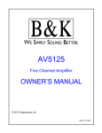
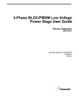
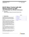
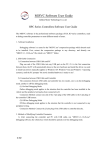
Freescale Semiconductor
Application Note
Document Number:AN4618
Rev. 0, 10/2012
Sensorless BLDC Motor Control
Using S12G240 Based on HVAC
Platform
by:
Zhen Liu, Peng Chen, and Changhao Shi
Contents
1 Introduction
1
Introduction................................................................1
This application note describes the design of a three-phase
sensorless BLDC motor drive with back-EMF zero-crossing.
It is based on Freescale’s MC9S12G240 MCU that can be
effectively used for motor control applications.
2
S12G family features................................................1
3
BLDCM theory.........................................................2
4
System Design Concept............................................3
The concept of the application is that of a speed-closed loop
drive using back-EMF zero-crossing technique for positional
detection. It serves as an example of a sensorless BLDC motor
control system using Freescale’s MCU and three-phase
BLDC/PMSM low-voltage motor control drive. It also
illustrates the usage of general on-chip peripherals for motor
control applications, controller features, basic BLDC motor
theory, system design concept, hardware implementation,
software design including the FreeMaster software
visualization tool, application setup, and demo operation.
5
Hardware...................................................................4
6
Software...................................................................10
7
Demo setup and operation.......................................13
8
References...............................................................15
2 S12G family features
On-chip modules available within the S12G family include the
following features:
• S12 CPU core, 25 MHz bus
• Up to 240 KB on-chip flash with ECC
• Up to 4 KB EEPROM with ECC
• Up to 11 KB on-chip SRAM
• Up to one multiscalable controller area network
(MSCAN) module
© 2012 Freescale Semiconductor, Inc.
BLDCM theory
•
•
•
•
•
Supporting CAN protocol 2.0 A/B
Up to three serial communication interface (SCI) modules. Supporting LIN communications
Precision fixed voltage reference for analog-to-digital conversion (ADC)
1 MHz internal oscillator
On-chip voltage regulator for input supply and internal voltages
3 BLDCM theory
The brushless DC (BLDC) motor (BLDC is a rotating electric machine with a classic three-phase stator like that of an
induction motor; the rotor has surface-mounted permanent magnets. It is also referred to as an electronically-commuted
motor. There are no brushes on the rotor and the commutation is performed electronically at certain rotor positions. The
stator is usually made from magnetic steel sheets. A typical cross section of a BLDC Motor is shown in Figure 1. The statorphase windings are inserted in the slots (distributed winding) or they can be wound as one coil onto the magnetic pole.
Because the air-gap magnetic field is produced by permanent magnets, the rotor magnetic field is constant.
Figure 1. BLDC motor ontology
The magnetisation of the permanent magnets and their displacement on the rotor is chosen so that the shape of back-EMF,
that is, the voltage induced on the stator winding due to rotor movement, is trapezoidal. This allows the DC voltage (see
Figure 2 ) with a rectangular shape to be used to create a rotational field with low-torque ripples.
Sensorless BLDC Motor Control Using S12G240 Based on HVAC Platform, Rev. 0, 10/2012
2
Freescale Semiconductor, Inc.
System Design Concept
Figure 2. Phase voltage system of a BLDC motor
4 System Design Concept
4.1 System specification
The motor control system is designed to drive a three-phase, BLDC motor in a speed and torque-closed loop. The application
meets the following performance specifications:
• It has a sensorless BLDC motor control using back-EMF zero-crossing sensing.
• It is targeted at the MC9S12G240 controller.
• The application is running on a three-Phase BLDC/PMSM low-voltage motor control drive.
• Control technique incorporates:
• Sensorless control with speed and torque-closed loop
• Analog-to-digital converter (ADC) for zero-crossing sensing
• Start from any motor position with rotor alignment
• Manual interface (rotary switch, push-button control)
• FreeMASTER software remote monitor
4.2 Sensorless drive concept
The sensorless BLDC motor drive concept shown in Figure 3 was chosen. The sensorless rotor position technique developed
detects the zero-crossing points of back-EMF induced in the motor windings. The phase back-EMF zero-crossing points are
sensed while one of the three-phase windings is not powered. The obtained information is processed in order to commutate
the energized phase pair and control the phase voltage, using pulse width modulation (PWM).
Sensorless BLDC Motor Control Using S12G240 Based on HVAC Platform, Rev. 0, 10/2012
Freescale Semiconductor, Inc.
3
Hardware
Figure 3. System configuration
5 Hardware
5.1 Hardware outline
The BLDC sensorless application runs on Freescale’s HVAC Central Control Board, HVAC Motor Control Board, and
45ZWN24-40 motor produced by LINIX. See Figure 4.
Sensorless BLDC Motor Control Using S12G240 Based on HVAC Platform, Rev. 0, 10/2012
4
Freescale Semiconductor, Inc.
Hardware
Figure 4. System configuration
5.2 Component description
5.2.1 HVAC Central Control Board
The HVAC Central Control Board includes PWM generation and deadtime set hardware circuit, and fault handling hardware
circuit for BLDC motor control.
5.2.1.1
PWM hardware generation & deadtime set
Figure 5 is PWM generation and deadtime set hardware circuit, which includes RC delay circuit, and AND gate circuit.
Sensorless BLDC Motor Control Using S12G240 Based on HVAC Platform, Rev. 0, 10/2012
Freescale Semiconductor, Inc.
5
Hardware
Figure 5. PWM hardware generation and deadtime set circuit diagram
Figure 6. Phase A PWM oscilloscope wave
Figure 5 is the circuit diagram for PWM phase A signal generation; phase B and phase C are the same. Figure 6 is phase A
PWM Oscilloscope wave. From Figure 6, it can inferred that the left deadtime is 1.48 µs, and the right deadtime is 1.2 µs.
High-side and low-side PWM signal of every bridge for inverter is generated by a bridge PWM signal and GPIO’s level
signal.
PWM signal generation
PWM generation: When PWMA signal is at high level, PWMA_/HS_IN is also at high level as pins 2 and 3 of jumper J15
are shorted (See Figure 5). At this moment, CTRLA signal is at high level and consequently, PWMA_LS_IN is also at high
level as pins 2 and 3 of jumper J14 are shorted. Thus, phase A low-side MOSFET conducts. See Figure 5. Similarly, when
PWMA signal is at low level, phase A high-side MOSFET conducts.
Deadtime set
The PWM deadtime is generated by RC delay circuit. The time difference between the charging and discharging of the RC
circuit is called deadtime. The deadtime is generated only by hardware and not software. The RC’s charge or discharge
equation is:
Sensorless BLDC Motor Control Using S12G240 Based on HVAC Platform, Rev. 0, 10/2012
6
Freescale Semiconductor, Inc.
Hardware
When the PWMA signal at high level, the high-side bridge signal is charged through R69, D19, and C55 branch and the lowside bridge signal is charged through R72, C56 branch. See Figure 5. The high-side bridge charge time is shorter than the
low-side bridge. When the PWMA signal is at low level, the low-side bridge discharge time is shorter than the high-side
bridge. The charge or discharge time difference is the deadtime.
The deadtime can be calibrated by software, using the SPI command between the MC9S12G240 MCU and MC33937, to
calibrate deadtime. The details will be described in Software.
5.2.1.2
Fault handling
Figure 7. Hardware fault handling
Figure 7 shows the HVAC Central Control Board circuit diagram including overcurrent (OC) and undervoltage (UV)
handling by hardware.
Taking into account only PWMA signal, when the situation of overcurrent or undervoltage occurs:
• The output of OR gate (U2A) is at high level and pins 1 and 2 of jumper J8 are shorted, as the output of RS trigger, Q,
is at high-level, and Q is at low-level.
• Pins 1 and 2 of both the jumpers J9 and J10 are shorted; FLT_Q (RS trigger's Q) and PWMA_/HS_IN are the inputs to
the OR gate (MC74ACT32DG), the output PWMA_/HS_OUT is at high level. This output is the inverter high-side
PWM signals of the predriver MC33937.
• Similarly, FLT_/Q (RS trigger's Q) and PWMA_LS_IN are the input of AND gate (MC74ACT32DG) and the output
PWMA_LS_OUT is at low-side. This output is the inverter low-side PWM signals of the predriver MC33937.
So the six PWM signals of the inverter (PWMA_/HS_IN, PWMB_/HS_IN, PWMC_/HS_IN, (PWMA_/LS_IN, PWMB_/
LS_IN, and PWMC_/LS_IN,) are ineffective and timely protect the motor from being destroyed.
NOTE
When the OC or UV faults are cleared, the RS triggers must be reset and held, before
starting the motor.
Sensorless BLDC Motor Control Using S12G240 Based on HVAC Platform, Rev. 0, 10/2012
Freescale Semiconductor, Inc.
7
Hardware
The HVAC Central Control Board needs needs the following jumper setting before the first usage:
• Short pins 1 and 2 of J14, J15, J16, J17, J19, and J20
• Short pins 2 and 3 of J8, J9, J10 and J11.
The user must pay attention to a correct driver USB/SCI installation. All about the driver installation is also included in the
board user’s manual, HVAC PLATFORM User Guide.
5.2.2 HVAC Motor Control Board
The HVAC Motor Control Board include power stage, predriver MC33937, and the sample circuit for BLDCM control.
5.2.2.1
DC_Bus current sample circuit
Figure 8 shows the DC_Bus current sample circuit. The input is pressure value of sampling resistance.
Figure 8. DC_Bus current sample and conversion circuit
DC_Bus current sample is needed to conduct current loop PI regulator and/or overcurrent software protection. In this demo
board, the sample resistor is 0.01 Ω, due to current’s positive and negative conduction, 2.5 V bias voltage is needed. The
differential amplifier equation is:
The maximum current cannot exceed 10 A.
5.2.2.2
Overvoltage fault handling
Figure 9 shows the power stage including three-phase inverter, overvoltage protection hardware circuit, and filtering
capacitance.
Sensorless BLDC Motor Control Using S12G240 Based on HVAC Platform, Rev. 0, 10/2012
8
Freescale Semiconductor, Inc.
Hardware
Figure 9. Power stage with overvoltage hardware protection
Due to voltage fluctuation or motor stalling etc, the DC_Bus voltage can rise. Overvoltage can destroy the hardware circuit
board or motor, so corresponding step must be needed.
In this demo, a braking resistor and a MOSFET is installed in series between DCB_POS and DCB_NEG(the yellow line
range). If DC_Bus voltage is more than the preset maximum voltage, MOSFET conducts, the energy is lost through braking
resistor, and as a result, DC_Bus voltage falls. The hardware protects the board from overvoltage.
5.2.2.3
DC-DC buck circuit
Figure 10. 24–12 V DC-DC buck circuit
The motor control board includes two DC-DC buck circuits; one of these is 24–12 V DC buck circuit. See Figure 10. This
circuit is designed to not only run 24 V rated voltage BLDCM but also run 12 V rated voltage BLDCM. In addition, it can
eliminate DC_Bus ripple if 12 V rated voltage BLDCM is used.
5.2.3 Motor 45ZWN24-40 (Produced by Linix)
The following motor is used for the BLDC sensorless application. Of course, other motors can also be adapted to the
application, just by defining and changing the motor-related parameters. A detailed motor specification is shown in Table 1.
Sensorless BLDC Motor Control Using S12G240 Based on HVAC Platform, Rev. 0, 10/2012
Freescale Semiconductor, Inc.
9
Software
Table 1. Electrical Characteristics of Linix 45ZWN24-40 Motor
Characteristic
Symbol
Min
Reference Winding Voltage
Vt
Jm
Speed @ Vt
Torque Constant
Kt
Voltage Constant
Typ
Max
Units
24
V
-
-
4000
rpm
-
-
-
Nm/A
-
-
-
V/rpm
Terminal Resistance
Ke
-
-
-
Ω
Winding Inductance
Rt
-
-
-
mH
Continuous Current
L
-
-
-
A
Number of Pole Pairs
Ics
-
-
-
-
-
-
-
°C
Temperature Rating
The HVAC Central Control Board and HVAC Motor Control Board use cable to interconnect. A detailed description,
including the hardware specification of the HVAC Central Control Board, is located in the Automotive HVAC Control
Platform Fact Sheet, available on freescale.com. Short the pins of jumper J25 before the first usage of the HVAC Central
Control Board.
6 Software
The main software structure is shown in Figure 11.
Sensorless BLDC Motor Control Using S12G240 Based on HVAC Platform, Rev. 0, 10/2012
10
Freescale Semiconductor, Inc.
Software
Figure 11. Main software flow chart
The software was ported from MC9S12G128 to MC9S12G240. The AD sample and PWM signal generation are different
from MC9S12G128 due to different hardware topology. PWM deadtime is generated by RC delay circuit, and by means of
hardware using the MC33937 driver.
6.1 MOSFET driver configuration
For correct operation of the MC33937, it must be configured. This driver is able to configure only via SPI communication.
There are two more files, providing SPI communication between the MCU and the driver, and for configuring the MOSFET
driver. In the spi_comm.h header file, there are configuration and status constants defined for the MC33937 driver. In the
spi_comm.c file there are SPI communication functions and configuration function for the MC33937 driver. The SPI
communication isn’t used only for driver configuration, but also for diagnosing this driver. A spicom driver is used.
6.2 PWM generation and timers
The PWM module of MC9S12G240 has 8 PWM channels. In this application, PWM0 and PWM1 are concatenated into one
16-bit channel, to generate AD sample hardware trigger delay time. The PWM channel pairs PWM2 and PWM3, PWM4 and
PWM5; and PWM6 and PWM7, are concatenated into one 16-bit channel.
In this application, two 8-bit PWM channels are concatenated into one 16-bit PWM channel in order to improve PWM
resolution and PI regulator stability. The other reason is that it increases AD sample interrupt interval from 10 µs to 50 µs.
This can be explained as follows:
Sensorless BLDC Motor Control Using S12G240 Based on HVAC Platform, Rev. 0, 10/2012
Freescale Semiconductor, Inc.
11
Software
When the bus frequency is 25 MHz, and the 8-bit PWM is selected, the maximum value of MOD is 255, and so, the PWM
period is about 10 µs. Due to synchronization between PWM and AD sample, the AD sample interrupt intervals is about 10
µs, which is too small.
Generally, the PWM frequency is 16 kHz or 20 kHz. When two 8-bit PWM channels are concatenated into a 16-bit channel
and the MOD of 16-bit PWM channel is set to 1250, the PWM sample period is 50 µs. So, the PWM frequency is 16 kHz and
the interval time of AD sample interrupt is 50 µs.
The BLDC motor uses two timers. The Timer Module channel 1 serves as PWM commutation, the channel 2 serves as 1 ms
timer interrupt, which is used as speed loop regulator and current loop regulator timebase.
6.3 PWM deadtime calibration
MC33937 is a FET predriver designed for three-phase motor control. The MC33937 interfaces to a MCU via six direct input
control signals, and SPI port for device setup etc.
The deadtime is set by sending the deadtime command (100x xxx1).
Figure 12. PWM deadtime calibration comparison diagram
Figure 12 is PWM deadtime calibration diagram. Referring to the left and right parts of Figure 12, it can be seen that:
• When the calibration value is 600 (left part), the left deadtime is 1.28 µs, and the right deadtime is 1.76 µs.
• When the calibration value is 2000 (right part), the left deadtime is 2.28 µs, and the right deadtime is 2.32 µs.
Usually, the deadtime set for MOSFET is about 1 µs, so the calibration value is set to 600.
6.4 AD conversion
Following is the configuration of analog-to-digital conversion channel:
• Single conversion mode
• Left-justified result data
• external trigger control
• 10-bit resolution
• 6.25 MHz ADC clock
The ADC sample channel is non-conduct phase according to the sector rotor located. The task of AD interrupt program is to
sample non-conduct phase voltage and DC Bus current or voltage and detect fault (overvoltage)and back-EMF zero-crossing
point. The AD sample must be synchronized with PWM due to mutual inductance and DC_Bus current envelope.
Sensorless BLDC Motor Control Using S12G240 Based on HVAC Platform, Rev. 0, 10/2012
12
Freescale Semiconductor, Inc.
Demo setup and operation
6.5 Fault handling
There are three IRQ event interrupts to handle fault. An IRQ event interrupt is called in the case of overcurrent and
undervoltage detection. An IRQ event interrupt is called in the case of under-voltage or over-current,.
When fault is detected, turn off all the six PWM signals. The state of the motor changes from fault to stop state only when the
fault is cleared.
6.6 Manual user’s interface
In the HVAC Central Control Board, there are two knobs, one knob is used to control BLDC motor while the other is used to
control stepper and servo motor. Clicking the knob is used for the start/stop function. Rotating the knob is used for
increasing/decreasing the speed. Rotating the knob clockwise increases revolutions per minute (rpm) while rotating it
anticlockwise decreases rpm. The default and minimum rpm is 800 whereas the maximum rpm is 1600. The step of speed
change is 200 rpm.
6.7 FreeMASTER communication
Serial communication using the SCI module was implemented for remote control using FreeMASTER. The host computer is
connected to the controller via a USB cable. The computer USB port works as a virtual COM port. Signal conversion from
USB form to SCI form, and vice versa, is done by the USB/SCI bridge.
More information can be found in LVMCDBLDCPMSMUG : 3-Phase BLDC/PMSM Low-Voltage Motor Control Drive
User's Guide, available on freescale.com.
6.8 Others
Finally, motor parameters, alignment, and starting constants are stored in the main.h file. The motor used in this application is
different from that used in the reference design of MCS12G128, so the motor parameters are logically different.
7 Demo setup and operation
For demonstrating the operation, this demo was built and is available for customers.
7.1 Hardware setup
The HVAC Demo Board includes one BLDC motor, three flap motors, one HVAC Central Control Board, and one HVAC
Motor Control Demo Board. See Figure 13.
Sensorless BLDC Motor Control Using S12G240 Based on HVAC Platform, Rev. 0, 10/2012
Freescale Semiconductor, Inc.
13
Demo setup and operation
Figure 13. HVAC Demo Board
Following are the steps needed to operate to run the sensorless BLDC motor:
1. Plug the power supply jack connector to the HVAC Demo Board connector J21.
2. Connect the USB BDM cable to the PC and to the HVAC Central Control Board J5.
3. Check the jump settings of J14, J15, J16, J17, J19, J20 on the HVAC Central Control Board. Phase A low-side PWM
signal, phase A high-side PWM signal, phase B low-side PWM signal, phase B high-side PWM signal, phase C lowside PWM signal, and phase C high-side PWM signal (pins 2 and 3 of jumpers J14, J15, J16, J17, J19, and J20 shorted)
must be in position.
4. Check the jump settings of J8, J9, J10, J11 on the HVAC Central Control Board. Outside DC_Bus current detection
circuit (pins 1 and 2 of jumper J11 shorted), overcurrent or undervoltage fault signals to RS trigger’s S input terminal
(pins 1 and 2 of J8 shorted), inverter high-side PWM signal hardware protection (pins 1 and 2 of jumper J9 shorted),
inverter low-side PWM signal hardware protection (pins 1 and 2 of jumper J10 shorted) must be in position.
5. Check the jump settings of J25 on the HVAC Motor Control Board. 12 V power supply to MC33937 (J25 shorted)
must be in position.
Figure 14. HVAC Central Control Board
Sensorless BLDC Motor Control Using S12G240 Based on HVAC Platform, Rev. 0, 10/2012
14
Freescale Semiconductor, Inc.
References
Figure 15. HVAC Motor Control Demo Board
7.2 Software setup
Source code is a part of this application note. Source code is written in CodeWarrior v. 5.1. USB/SCI driver installation is
required prior to first usage of FreeMASTER. Driver installation is described in the MS Word file “Installation USB/SCI
Bridge manual”. After successfully installing the driver, select a virtual COM port attached to the USB port, and then
FreeMASTER is ready to use.
8 References
The following reference documents are available on freescale.com
• MC9S12GRMV1: MC9S12G Family Reference Manual and Data Sheet
• S12GHVACCTLPLTFS: Automotive HVAC Control Platform Fact Sheet
• LVMCDBLDCPMSMUG: 3-Phase BLDC/PMSM Low-Voltage Motor Control Drive User's Guide
Sensorless BLDC Motor Control Using S12G240 Based on HVAC Platform, Rev. 0, 10/2012
Freescale Semiconductor, Inc.
15
How to Reach Us:
Home Page:
www.freescale.com
Web Support:
http://www.freescale.com/support
USA/Europe or Locations Not Listed:
Freescale Semiconductor
Technical Information Center, EL516
2100 East Elliot Road
Tempe, Arizona 85284
+1-800-521-6274 or +1-480-768-2130
www.freescale.com/support
Europe, Middle East, and Africa:
Freescale Halbleiter Deutschland GmbH
Technical Information Center
Schatzbogen 7
81829 Muenchen, Germany
+44 1296 380 456 (English)
+46 8 52200080 (English)
+49 89 92103 559 (German)
+33 1 69 35 48 48 (French)
www.freescale.com/support
Japan:
Freescale Semiconductor Japan Ltd.
Headquarters
ARCO Tower 15F
1-8-1, Shimo-Meguro, Meguro-ku,
Tokyo 153-0064
Japan
0120 191014 or +81 3 5437 9125
[email protected]
Asia/Pacific:
Freescale Semiconductor China Ltd.
Exchange Building 23F
No. 118 Jianguo Road
Chaoyang District
Beijing 100022
China
+86 10 5879 8000
[email protected]
Document Number: AN4618
Rev. 0, 10/2012
Information in this document is provided solely to enable system and software
implementers to use Freescale Semiconductors products. There are no express or implied
copyright licenses granted hereunder to design or fabricate any integrated circuits or
integrated circuits based on the information in this document.
Freescale Semiconductor reserves the right to make changes without further notice to any
products herein. Freescale Semiconductor makes no warranty, representation, or
guarantee regarding the suitability of its products for any particular purpose, nor does
Freescale Semiconductor assume any liability arising out of the application or use of any
product or circuit, and specifically disclaims any liability, including without limitation
consequential or incidental damages. "Typical" parameters that may be provided in
Freescale Semiconductor data sheets and/or specifications can and do vary in different
applications and actual performance may vary over time. All operating parameters,
including "Typicals", must be validated for each customer application by customer's
technical experts. Freescale Semiconductor does not convey any license under its patent
rights nor the rights of others. Freescale Semiconductor products are not designed,
intended, or authorized for use as components in systems intended for surgical implant
into the body, or other applications intended to support or sustain life, or for any other
application in which failure of the Freescale Semiconductor product could create a
situation where personal injury or death may occur. Should Buyer purchase or use
Freescale Semiconductor products for any such unintended or unauthorized application,
Buyer shall indemnify Freescale Semiconductor and its officers, employees, subsidiaries,
affiliates, and distributors harmless against all claims, costs, damages, and expenses, and
reasonable attorney fees arising out of, directly or indirectly, any claim of personal injury
or death associated with such unintended or unauthorized use, even if such claims alleges
that Freescale Semiconductor was negligent regarding the design or manufacture of
the part.
RoHS-compliant and/or Pb-free versions of Freescale products have the functionality and
electrical characteristics as their non-RoHS-complaint and/or non-Pb-free counterparts.
For further information, see http://www.freescale.com or contact your Freescale
sales representative.
For information on Freescale's Environmental Products program, go to
http://www.freescale.com/epp.
Freescale™ and the Freescale logo are trademarks of Freescale Semiconductor, Inc.
All other product or service names are the property of their respective owners.
© 2012 Freescale Semiconductor, Inc.