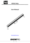
Download USER MANUAL - Intella System
Transcript
USER MANUAL
INDEX
SAFETY INSTRUCTIONS ................................................................. 2
PREPARATION FOR USE .................................................................. 3
DMX-512 control connection ..................................................... 3
DMX-512 connection with DMX terminator .................................. 3
Storm400 specifications ........................................................... 4
OPERATION .................................................................................. 5
Display Menu .......................................................................... 5
DMX Control Summary ............................................................. 6
DMX functions and values ............................................................... 6
CLEANING AND MAINTENANCE ....................................................... 9
INSTALLATION ...................................................................... 10
TECHNICAL SPECIFICATIONS .................................................. 10
1
SAFETY INSTRUCTIONS
This device has left the factory in perfect condition. In order to
maintain this condition and to ensure a safe operation, it
is absolutely necessary for the user to follow the safety instructions and
warning notes written in this user manual.
This device falls under protection-class I. Therefore it is essential that
the device should be earthed.
The electric connection must carry out by qualified person.
If the external flexible cable or cord of this luminaire is damaged,
it shall be exclusively replaced by the manufacturer or his service agent
or a similar qualified person in order to avoid a hazard.
Make sure that the available voltage is not higher than stated at the
end of this manual.
Make sure the power cord is never crimped or damaged by sharp edges.
If this would be the case, replacement of the cable must be done by an
authorized dealer.
Always disconnect from the mains, when the device is not in use or
before cleaning it. Only handle the power cord by the plug. Never pull
out the plug by tugging the power cord.
Never look directly into the light source, as sensitive persons
may suffer an epileptic shock.
Important:
Damages caused by the disregard of this user manual are not
subject to warranty. The dealer will not accept liability for any
resulting defects or problems.
2
PREPARATION FOR USE
UNPACKING
Thank you for having chosen Intella LED lighting
Unpack the device, inside the box you should find:
The fixture device
One power cable
One XLR connection cable
This manual
Please check carefully that there is no damage caused
by transportation. Should there be any , consult your dealer and
don’t install this device.
DMX-512 control connection
The product has a DMX 512 input fitted with 3-pin XLR connectors.
Screened cables in compliance with EIA RS-485 specifications and the
following characteristics must be used for connections:
- 2 conductors plus screen
- 120Ohm impedance
- low capacitance
- max. transmission rate 250kBaud.
DMX-512 connection with DMX terminator
For installations where the DMX cable has to run a long distance or is in
an electrically noisy environment, such as in a discotheque, it is
recommended to use a DMX terminator. This helps in preventing
corruption of the digital control signal by electrical noise. The DMX
terminator is simply an XLR plug with a 120 OHM resistor connected
between pins 2 and 3, which is then plugged into the output XLR socket
of the last fixture in the chain.
AC Power Connection
The auto-ranging power supply automatically adjusts to AC power from
110-240 volts nominal at 50/60 Hz.
The current required by the Storm 400 is 4.5 amps. To avoid overload,
allow one 4.5 amp branch circuit per fixture to operate the Storm 400
model at full power.
Use 2.5 mm2 (14 AWG) or larger power feed cables and keep runs as
short as possible.
Do not link more than 4 fixtures for the one single power chain.
3
Storm400 specifications
Light Source : 324pcs RGB/White 5050 LED, no ultraviolet radiation
Life Time: More than 50000 hours for the LED light source
Output: 35000 for white version,15000lm for RGB version
DMX mode: 1/3/4/6/7/16
Dimmer: 16Bit Dimmer
Operating Mode: DMX Mode /Master-slave mode
Power: AC110-240V 50/60Hz 300W
Cooling: Diecasting heatsink , Convection cooling, no fans, no noise
Over Heat Protect: With temperature sensor to extend the lamp life
LED Scan Rate: 7000Hz LED scan rate
Size: Compact size, 2.8kg
Effects:
9 segments LED/ 3 segments for RGB version, can be controlled
separately, with 16bit dimmer
Flash duration can be set from 0 to 650ms in DMX mode(except 1
channel mode) 0-30 flashes per second
Ramp up effect: Light gradually increases in intensity, then blacks out
Ramp down effect: Light flashes to full intensity, then gradually fades.
Ramp up-down effect: Light gradually increases and decreases
Radom flash effect: Light flashes randomly with variable rate and
intensity. Multiple units flash independently of each other.
Blinder effect: the light remains on (Lamp power is electronically
regulated to prevent the lamp from overheating)
Lightning effect: the flashes simulate lightning, duration is not
adjustable.
Spikes: the lamp remains dimly illuminated between flashes, set flash
intensity, duration and rate as normal.
NOTE!
The brightness will decrease gradually when the led
temperature is over 55℃,and if over 70℃,then will black out
4
OPERATION
Display Menu
Menu
Sub-menu
Address
Set DMX Address
Mode 1
Mode 2
Mode 3
Auto
Mode 4
Mode 5
Mode6
Speed
000-031
W1/Red
Color
W2/Green
W3/Blue
All on
White1 /Red1 on
White2 /Red2 on
White3 /Red3 on
White4/Green1
on
Test LED
White5/Green2
on
White6/Green3
on
White7/Blue1 on
White8/Blue2 on
White9/Blue3 on
Temp
<ENTER>
Time
<ENTER>
DMX Status
Display Mode
Temp Unit CS
Factory Settings
Config
Channel Mode
Key Mode
001-512
Auto Mode 1
Auto Mode 2
Auto Mode 3
Auto Mode 4
Auto Mode 5
Auto Mode 6
Auto Run Speed
0-255
0-255
0-255
All On + Individual LED Segment
Testing
Internal Temperature
Total Run Time
Value Hold
Holds the last DMX values if signal is lost
Value Clear
Clears the DMX values if signal is lost
LCD Display ON or Auto OFF
Celsius degree and Fahrenheit degree for
selection
W1-W9
Channel 1 (1ch DMX mode)
Channel 3 (1ch DMX mode)
Channel 4 (1ch DMX mode)
Channel 6 (1ch DMX mode)
Channel 7 (1ch DMX mode)
Channel 16 (1ch DMX mode)
Pixel 3 (3ch DMX pixel control)
Pixel 9 (9ch DMX pixel control)
Key Lock
Menu buttons lock after 30sec of
inactivity (push more than once to
5
Load
Default
temporarily unlock buttons).
Key Unlock
Menu buttons are not locked.
Load Default Resets all values to default
DMX Control Summary
Intensity
Flash intensity can be set from minimum (blackout) to maximum in all
DMX modes except 1 channel mode (where it is always at maximum
intensity). A special pixel mode enables the fixture to be used as a
blinder, where the intensity of blinder colour can be set.
Duration·
Flash duration can be set from 0 to 650 ms on 50 Hz power supplies, or
0 to 530 ms on 60 Hz power supplies in 3, 4, 6 or 7 channel DMX
modes. Flash duration is fixed in 1-channel DMX.
Rate
Flash rate can be set from 0 flashes per second to 25 flashes per
second on 50 Hz power supplies or from 0 to 30 flashes per second on
60 Hz power supplies, when the fixture is set to 3, 4, 6 or 7 channel
DMX mode. The flash rate is also controllable in 1-channel DMX mode.
Programmed Effects
Six programmed effects are available in 4 and 7 channel DMX modes.
The effects may be altered using the intensity, duration, and rate
controls
DMX functions and values
1 Channel Mode
CH Values
Functions
1
0-255
Strobe rate(0-30HZ)
3 Channel Mode
CH Values Functions
1
0-255
Master Dimmer (0-100%)
2
0-255
Flash duration(0-full on)
3
0-255
Strobe rate(0-30HZ)
6
4 Channel Mode
CH Values
Functions
1
0-255
Master Dimmer (0-100%)
2
0-255
Flash duration(0-full on)
3
0-255
Strobe rate(0-30HZ)
0-5
No effect
6-42
Ramp up effect
43-85
Ramp down effect
4
86-128
Ramp up-down effect
129-171 Random effect
172-214 Lightning effect
215-255 Spike effect
6 Channel Mode
CH
Values
Functions
1
0-255
Master
2
0-255
Red/Segment1-3 Dimmer(0-100%)
3
0-255
Green/Segment4-6 Dimmer(0-100%)
4
0-255
Blue/Segment7-9 Dimmer(0-100%)
5
0-255
Flash duration(0-full on)
6
0-255
Strobe rate(0-30HZ)
Dimmer (0-100%)
7 Channel Mode
CH Values
Functions
1
0-255
Master Dimmer (0-100%)
2
0-255
Red/Segment1-3 Dimmer(0-100%)
3
0-255
Green/Segment4-6 Dimmer(0-100%)
4
0-255
Blue/Segment7-9 Dimmer(0-100%)
5
0-255
Flash duration(0-full on)
6
0-255
Strobe rate(0-30HZ)
0-5
No effect
6-42
Ramp up effect
7
43-85
Ramp down effect
86-128
Ramp up-down effect
7
129-171
172-214
215-255
Random effect
Lightning effect
Spike effect
16 Channel Mode
CH Values
Functions
1
0-255
Master Dimmer (0-100%)
2
0-255
Red/Segment1-3 Dimmer(0-100%)
3
0-255
Green/Segment4-6 Dimmer(0-100%)
4
0-255
Blue/Segment7-9 Dimmer(0-100%)
5
0-255
Flash duration(0-full on)
6
0-255
Strobe rate(0-30HZ)
0-5
No effect
6-42
Ramp up effect
43-85
Ramp down effect
7
86-128
Ramp up-down effect
129-171 Random effect
172-214 Lightning effect
215-255 Spike effect
8
0-255
Red1/Segment1 Dimmer(0-100%)
9
0-255
Green1/Segment2 Dimmer(0-100%)
10 0-255
Blue1/Segment3 Dimmer(0-100%)
11 0-255
Red2/Segment4 Dimmer(0-100%)
12 0-255
Green2/Segment5 Dimmer(0-100%)
13 0-255
Blue2/Segment6 Dimmer(0-100%)
14 0-255
Red3/Segment7 Dimmer(0-100%)
15 0-255
Green3/Segment8 Dimmer(0-100%)
Blue3/Segment9
16 0-255
Dimmer(0-100%)
Pixel Mode
3 Channel Values
0-5
1
6-255
0-5
2
6-255
Blinder intensity
Blackout
Segment 1
Blackout
Segment 2
8
3
0-5
6-255
Blackout
Segment 3
Pixel Mode (White)
9 Channel Values Blinder intensity
0-5
Blackout
1
6-255
Segment 1 Dimmer
0-5
Blackout
2
6-255
Segment 2 Dimmer
0-5
Blackout
3
6-255
Segment 3 Dimmer
0-5
Blackout
4
6-255
Segment 4 Dimmer
0-5
Blackout
5
6-255
Segment 5 Dimmer
0-5
Blackout
6
6-255
Segment 6 Dimmer
0-5
Blackout
7
6-255
Segment 7 Dimmer
0-5
Blackout
8
6-255
Segment 8 Dimmer
0-5
Blackout
9
6-255
Segment 9 Dimmer
When the lighting is under the Pixel mode, the brightness will
be only 40% of Maximum power, and
it can be used as
wash/flood lighting.
CLEANING AND MAINTENANCE
We recommend a frequent cleaning of the device. Please use a soft lintfree and moistened cloth. Never use alcohol or solvents!
CAUTION!
Disconnect from mains before starting maintenance operation.
There are no servicable parts inside the device. Maintenance and
9
service operations are only to be carried out by authorized dealers.
If you need any spare parts, please use genuine parts.
If the power supply cable of this device becomes damaged, it has to be
replaced by authorized dealers only in order to avoid hazards.
If you have further questions, please contact your dealer.
INSTALLATION
The device must only be installed at a vibration-free, oscilation-free
and fire-resistant location.
TECHNICAL SPECIFICATIONS
Power supply: 110V~240V AC,50 Hz /60Hz
Power consumption: max. 300 W
Waterproof grade: IP 20
Net weight: 2.8 KGS
Remark: errors and omissions for every information given in this
manual except. All information is subject to change without prior notice.
10
INTELLA SYSTEM
A/S. #6 Youyi Road, Yongping Street, Baiyun District, Guangzhou, CHINA
[email protected]/[email protected]/www.intellasystem.com
TEL. +86 20 36297033. FAX. +86 20 86438560


