1
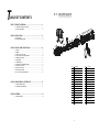
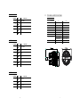
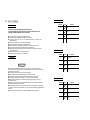
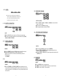
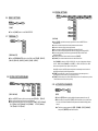
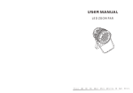
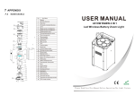
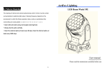
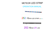
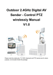
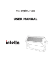
T
5.1
ABLE OF CONTENTS
MAINTENANCE
PART 1 PRODUCT (GENERAL)....................................................1.
1.1 -- TECHNICAL SPECIFICATIONS .....................................................1.
1.2 -- SAFETY WARNING ......................................................................2.
3
2
1
4
6
10
9
8
5
7
11
PART 2 INSTALLATION...............................................................3.
12
13
2.1--MOUNTING...................................................................................3.
2.2--POWER CONNECTION............................................................ .....3.
16
14
15
17
19
18
20
22
PART 3 DISPLAY PANEL OPERATION.........................................4.
3.1--BASIC................................................................................... ......4.
3.2--MENU......................................................................................... 4.
3.3--EDIT STATIC COLOUR................................................................ 5 .
3.4--ACTIVATING AUTO PROGRAMS.................................................. 5.
3.5--DMX512 SETTINGS..................................................................... 6.
3.6--RUN MODE................................................................................ . 5.
3.7--PERSONALITY............................................................................ 6 .
3.8--EDITING CUSTOM PROGRAMS ................................................ . 6.
3.9--SPECIAL SETTINGS.................................................................. . 7.
3.10-- WHITES SETTING .....................................................................7.
3.11-- WHITES BALANCE .................................................................. . 8.
3.12--A CTIVATE THE PASSWORD .................................................... .8.
PART 4 USING A DMX512 CONTROLLER.....................................9.
4.1--BASIC ADDRESSING................................................................. 9.
4.2--CHANNEL ASSIGNMENT.............................................................9.
21
28
23
29
30
24
25
27
26
序号
配 件 名 称
序号
配 件 名 称
1
Head cover
16
Connection boardd
2
Rubber seal
17
Drive support
3
Clear glass
18
Prive PCB
4
Lens holder up
19
Display PCB
5
Zoom lens
20
Casing2
6
Lens holder down
21
Power adaptor
7
Lens base
22
Power adaptor
8
Capture lens
23
3 XLR socket(male)
9
5 XLR socket(male)
LED board
24
10
Head structure
25
3 XLR socket(female)
11
Thermal protection device
26
5 XLR socket(female)
PART 5 APPENDIX......................................................................13.
12
Motor
27
Display lens
5.1--MAINTENANCE......................................................................... 13.
13
Connection disk
28
Abracket2
14
Power supply support
29
Secondary bracket2
15
Power supply
30
Adjusting stainkless steel knob
13
Ar2.d
1.1
CHANNEL
1
VALUE
0
FUNCTION
255
M ASTER DIMMER
TECHNICAL SPECIFICATIONS
LED MODULE
Voltage
2
0
255
RED
3
0
255
G REEN
0
5
0
255
150W
3W x 10
3W x 10
GREEN
3W x 10
3W x 10
BLUE
3W x 10
3W x 10
3W x7
3W x7
-40℃~45℃(operating)
-40℃~45℃(operating)
WHITE
W HITE
100~240V...50/60Hz
150W
BLUE
255
TZ IP
100~240V...50/60Hz
RED
Power
4
TZ
LED MODULE:
IP 67
IP RATING
Operation Temperature
Ar2.s
Dimensions
Weight
CHANNEL
VALUE
-20℃~40℃(startup)
-20℃~40℃(startup)
311x248.2x2.3mm
311x248.2x2.3mm
6.5Kg
6.5Kg
FUNCTION
1
0
255
MASTER DIMMER
2
0
255
RED
3
0
255
GREEN
4
0
255
BLUE
5
0
255
WHITE
6
0
255
STROBE
HSV
CHANNEL
VALUE
FUNCTION
1
0
255
HUE(0~100%)
2
0
255
SATURATION(0~100%)
3
0
255
VALUE(0~100%)
12
1
Arc.1
1.2 SAFETY WARNING
IMPORTANT
CHANNEL
【ALWAYS READ THE USER MANUAL BEFORE OPERATION. 】
【PLEA SE CONFIRM THAT THE POWER SUPPLY STATED ON THE PRODUCT IS THE
SAME AS THE MA INS POWER SUPPLY IN YOUR AREA.】
● This product must be installed by a qualified professional.
● Always operate the equipment as described in the user manual.
● A minimum distance of 0.5m must be maintained between the equipment and
combustible surface.
● The product must always be placed in a well ventilated area.
● Always make sure that the equipment is installed securely.
● DO NOT stand close to the equipment and stare directly into the LED light source.
● Always disconnect the power supply before attempting maintenance.
● Always make sure that the supporting structure is solid and can support the combined
weight of the products.
● The earth wire must always be connected to the ground.
● Do not touch the power cables if your hands are wet.
2
FUNCTION
0
255
2
0
255
GREEN
3
0
255
BLUE
RED
Ar1.d
CHANNEL
ATTENTION
● This product left the place of manufacture in perfect condition. In order to maintain this
condition and for safe operation, the user must always follow the instructions and safety warnings
described in this user manual.
● Avoid shaking or strong impacts to any part of the equipment.
● Make sure that all parts of the equipment are kept clean and free of dust.
● Always make sure that the power connections are connected correct and secure.
● If there is any malfunction of the equipment, contact your distributor immediately.
● When transferring the product, it is advisable to use the original packaging in which the
product left the factory.
● Shields, lenses or ultraviolet screens shall be changed if they have become damaged to such
an extent that their effectiveness is impaired.
●I t is important that the power cable is frequently inspected to ensure that there is no damagein
any position. If the power cable is damaged in any way, it should be replaced by a qualified electrical
technician.
●The lamp (LED) shall be changed if it has become damaged or thermally deformed.
VALUE
1
VALUE
FUNCTION
1
0
255
M ASTER D IMMER
2
0
255
RED
3
0
255
G REEN
4
0
255
BLUE
Arc.2
CHANNEL
VALUE
FUNCTION
1
0
255
RED
2
0
255
G REEN
3
0
255
BLUE
4
0
255
W HITE
11
CHANNEL
6
VALUE
FUNCTION
231
23 5
WHIT E 7: 6500 K
2 36
24 0
WHIT E 8: 7200 K
241
24 5
WHITE 9 : 8000K
2 46
25 0
W HITE 10 : 8500K
251
25 5
WHITE 11: 10000K
2 INSTALLATION
2.1
HANGING
STROBE
7
0
11
10
2 55
The fixture can be mounted in a
hanging position using the supporting
br acket.
Th e bra ck et s houl d be
se cured to the mounting trus s or
structure using a standard mounting
clamp. Please note that when hanging
the unit a safety cable should also be
used.
NO FU NCTION
1~20Hz
AUTO
8
0
20
NO FU NCTION
21
30
AUTO 1
31
40
AUTO 2
41
50
AUTO 3
51
60
AUTO 4
61
70
AUTO 5
71
80
AUTO 6
81
90
AUTO 7
91
1 00
AUTO 8
101
110
AUTO 9
111
1 20
AUTO 10
121
1 30
CUSTOM 1
131
1 40
CUSTOM 2
141
1 50
CUSTOM 3
151
1 60
CUSTOM 4
161
1 70
CUSTOM 5
171
1 80
CUSTOM 6
181
1 90
CUSTOM 7
191
2 00
CUSTOM 8
201
2 10
CUSTOM 9
211
2 20
CUSTOM 10
221
2 55
NO FU NCTION
0
2 55
When using CH8,AUTO01-AUTO10, this function activated
0
9
PRESET DIMMER SPEED FROM DISPLAY MENU
10
29
LINEAR DIMMER
30
69
NON LI NEAR DI MMER 1(fastest)
70
1 29
NON LI NEAR DI MMER 2
130
1 89
NON LI NEAR DI MMER 3
190
2 55
NON LI NEAR DI MMER 4(slowest )
0
255
ZOOM
000
2 00
NO FUNCTION
2 01
2 20
ZOOM RESET
2 21
2 55
NO FUNCTION
UPRIGHT
The fixture can be mounted in an
upright or sitting position using the
supporting brackets.
The LED MODULE can be mounted at any angle and in any
position. It is possible to further adjust the angle of the LED
MODULE using the two adjustment knobs located on the side of
the fixture.
2.2
@120V: 7 units may be connected in series
Note:
If the signal cable is over 60m between the DMX512 controller and fixture
or beween two fixtures, then a DMX signal amplifier is needed as well.
DIMMER SPEED
10
11
12
10
POWER CONNECTIONS
@ 220V: 14 units may be connected in series
AUTO SPEED ADJUST MENT
9
MOUNTING
3 DISPLAY PANEL OPERATION
3.1
BASIC
MENU
ENTER
scroll through the main menu or return
to the main menu.
enter the currently selected menu or
confirm the current function value.
scroll 'UP' through the menu list or increase
the value of the current function.
scroll 'DOWN' through the menu list or
decrease the value of the current function.
3
MENU ENTER
UP
DOWN
4 USING A DMX512 CONTROLLER
3.2
4.1
MENU
MENU
S TAT
W HI T
ZOO M
STRB
AUTO
● Connect all of the units in series using standard DMX512 signal cable or
the IP65 rated cable
provided.
● Set the DMX512 address in the【DMX】menu.
● It is possible to have the same DMX address or independent
addresses for each fixture.
R .( 0 ~2 5 5)
G .(0 ~2 55 )
B .( 0 ~2 5 5)
W.( 0~255)
Z. (0~25 5)
S.( 0~20)
RE D
GR EN
BL UE
AT.0 1
AT.0 2
4.2
AT.1 0
PR.0 1
PR .0 2
DMX
S LAV
DM X
D. (001~ 512)
P ERS
TOUR
AR C. 1
AR 1.D
AR C. 2
AR 2.D
AR 2.S
CHANNEL ASSIGNMENT
● Note: This product have three DMX512 channel configuration:
【TOUR】,【Arc.1】,【Ar1.d】,【Arc.2】,【Ar2.d】,【Ar2.s】 and
【HSV】
P R .1 0
RUN
BASIC ADDRESSING
TOUR
CHANNEL
S ET
FUNCTION
MASTER DIMMER
1
HS V
HS V Z
ED IT
VALUE
P R.0 1
P R.0 2
S C.0 1
S C.0 2
P R.10
S C.3 0
UP LD
RE ST
PAS S
PAS S
COLOR
UC
OF F
RGB W
RE D
GR EN
BLUE
WHI T
ZOOM
TIME
STR
B
TIME
FAD E
2
R. (0 ~25 5)
G. (0~25 5 )
B. (0 ~25 5)
W.( 0 ~25 5)
3
Z.(0~ 2 55 )
T.(0~2
55)
S
.(0 ~ 20
)
T.(0~2 55)
F.(0~2 55)
S END
R ES T
5
SAV E
BLAK
ZOOM
0
255
0
255
RED
(or STEP TIME when CUS.01 -CUS.10 in CH8 is activated)
GREEN
(or FADE TIME when CUS.01-CUS.10 in CH8 is activated)
BLUE
0
255
0
255
0
5
NO FUNCTION
WHITE
COLOR MACRO
DIM1
OFF
DE RR
255
4
END
END
DIM4
DIM3
DIM2
DIM
0
PO S1
P OS 2
BAS E
11
30
RED100%/GREEN UP/BLUE0%
31
50
RED DOWN/GREEN 100%/BLUE0%
51
70
RED 0%/GREEN 100%/BLUE UP
KEY
ON
OFF
71
90
RED 0%/GREEN DOWN/BLUE 100%
CAL
****
91
110
RED UP/GREEN 0%/BLUE100%
111
130
RED100%/GREEN 0%/BLU EDOWN
131
150
RED100%/GREEN UP/BLUE UP
151
170
RED DOWN/GREEN DOWN/BLUE 100%
171
200
RED100%/GREEN 100%P/BLUE100%/WHITE 100%
201
205
WHITE1:3200K
206
210
WHITE2:3400K
211
215
WHITE3:4200K
216
220
WHITE4:4900K
221
225
WHITE5:5600K
226
230
WHITE6:5900K
WT
RED
GR EN
B LUE
W HIT
W T.01
W T.02
R.(0 ~25 5)
G .(0 ~25 5)
B.(0 ~25 5)
W.(0~25 5)
W T.11
RGB W
ZO OM
RED
G RE N
B LU E
W H IT
R.(0 ~25 5)
G.( 0~2 55 )
B.(0 ~25 5)
W.(0 ~25 5)
P OS 1
1.(0 ~2 55)
2.(0 ~2 55)
P OS 2
4
6
9
3.11
EXTRA
3.3
CAL
MENU
EDIT STATIC COLOUR
00 00
MENU
STAT
◆ When the user enter 【 CAL】and input the correct password, the
hidden menu 【Cablid】,【default】 will appear on display panel, and
the user is able to reset the 【DEFAULT】values of all functions.
The default access code is UP + DOWN + UP + DOWN..
3.12
【STATIC COLOUR】
● Combine 【Red】, 【Green】, 【Blue】 and 【White】 to create an infinite
range of colors (0-255)
● Set the value of the 【Strobe】 (0-20Hz)
● Set the projection angle by using the 【ZOOM】
WHITES CALIBRATION
MENU
WT
WT01
WT02
Red
Green
Blue
White
(0~255)
(0~255)
(0~255)
(0~255)
(0~255)
(0~20)
Red
Green
Blue
White
ZOOM
Strob
(0~255)
(0~255)
(0~255)
(0~255)
WT11
3.4
【WT】
MENU
● Enter the 【CAL1】to select white color of different color temperature.
● There are 11 pre-programmed White colors can be edited by using 【 Red】,
【Green】, 【Blue】 & 【White】.
3.13
ACTIVATING AUTO PROGRAMS
AUTO
AT.10
PR.01
PR.02
RGB CALIBRATION
MENU
RGBW
PR.10
R.(0~255)
G.(0~255)
B.(0~255)
W.(0~255)
Red
Green
Blue
Whit
【AUTO】
● Select the target【AUTO】 program and press【ENTER】.
● Programs【AT.01】to【AT.10】are fully pre-programmed and will not be
altered by changes in【EDIT 】mode.
● Programs 【PR.01】to【PR.10】are fully pre-programmed and can be edited
in 【EDIT 】mode.
【RGBW】
● Enter the 【MENU】to adjust the RGWB parameter to make different whites.
● When the new setting is activated, the DMX controller choose
RGBW = 255,255,255, 255, the white color will be made by the actual
RGBW values on
the 【RGBW】.
3.5
3.14
RUN MODE
MENU
MENU
ZOOM
AT.01
AT.02
POS1
POS2
1.(0~255)
2.(0~255)
【ZOOM】
● Select the【ZOOM】range.【POS1】&【POS2】set the small position for the
zoom function.Note that when using DMX to control the fixture, the user will only
be able to access upto the set ZOOM position.It is not possible to adjust beyond
the set position.
8
RUN
DMX
SLAV
【RUN 】
● Enter the【RUN 】mode to set working mode.
● 【DMX】 mode is for using the DMX512 controller to control the fixtures.
● 【SLAV】 mode is for Master -- Slave operation.
5
3.9 SPECIAL SETTINGS
3.6
MENU
DMX512 SETTINGS
MENU
SET
UPLD
REST
PASS
PASS
DIM
DIM4
DIM1
DIM2
D(001~512)
DMX
SEND
REST
END
END
DIM3
OFF
COLOR
【DMX】
● Enter the【DMX】mode to set the DMX ADDRESS.
3.7
DERR
ZOOM
PERSONALITY
MENU
PERS
【SETTING】
TOUR
A RC.1
A R1.D
A RC.2
A R2.D
A R2.S
HSV
HSVZ
【PERSONALITY】
● Enter the【PERSONALITY】mode to select DMX mode:【TOUR】,【ARC.1】,
【AR1.D】,【ARC.2】,【AR2.D】,【AR2.S】,【HSV】 【HSVZ】.
OFF
RGBW
UC
BLAK
SLAV
POS1
POS2
BASE
● Select【UPLD】to upload the custom programs from the current MASTER unit to
the SLAVE units.
● In order to activate the upload function the password must be entered.
● Password is the same as the main access password.
● When uploading the MASTER and SLAVE units will display YELLOW.
● If an error occurs when uploading the MASTER and/or SLAVE units will display RED.
● On successful uploading of the custom programs the MASTER and SLAVE units
will display GREEN.
● In order to reset custom modes to default values select 【 REST】.
● 【COLOR】 is for activate/unactivate the color calibration functions.
When 【RGBW】is selected, on RGB = 255,255,255, the color is displayed as calibrated
in CAL2 -- RGBW. When 【COLOR】 is set 【OFF】, on RGB = 255,255,255, the RGB
values are not adjusted and the output is most powerful.
When [ UC ] is selected, the RGB output are adjusted to a standard preset universal color
which balances fixtures from different generations.
● 【DERR 】C hoose【Save】 in order to save the last DMX data incase of DMX signal error.
Choose【Black】i n order to blackout in case of DMX signal error.
3.8
● 【ZOOM】Calibrate the position of POS1&POS2.Set position as 0 for smallest zoom position.
EDITING CUSTOM PROGRAMS
MENU
EDIT
PR.01
PR.02
SC.01
SC.02
PR.10
SC.30
【EDIT CUSTOM】
selecf BASE for defaulf zoom position (zoom=0)
Red
Green
Blue
White
Zoom
Strobe
Time
Fade
(0~255)
(0~255)
(0~255)
(0~255)
(0~255)
(0~20)
(0~255)
(0~255)
● Enter the【EDIT 】mode to edit the custom programs【PR.01】to 【PR.10】.
● Each custom program has 30 steps that can be edited.
● Each step allows the creation of a scene using RED 【 Red】 , GREEN 【Green】 ,
BLUE 【Blue】, WHITE【White】, ZOOM【ZOOM】 , STROBE 【Strobe】,
TIME【Time】 & FADE【Fade】.
6
3.10
ACTIVATE THE PASSWORD
MENU
KEY
ON
OFF
【KEY】
● Enter the【KEY】mode to select whether the access password is on or off.
● When the fixture is set as PASS 【ON】, after 30 seconds or turn on the fixture
next time, the fixture will need an access password to enter the display menu
control.
Note: The factory access password is【UP】+【DOWN】+【UP】+【DOWN】,
8
then press 【ENTER】to confirm
the access.
7