1
PNEG-970
07-14-05
Series II Sweep Hopper With
Collector Ring
Installation & Operation Manual
PNEG-970
Catalog No. Slip Ring
Serial No.
Date of Purchase
The manufacturer reserves the right to improve its product whenever
possible and practical to do so. We reserve the right to change, improve,
and modify products at any time without obligation to make changes,
improvements, and modifications on equipment sold previously.
Table of Contents
Personnel operating or working around this equipment
should read this manual. This manual must be delivered
with equipment to its owner. Failure to read this manual
and its safety instructions is a misuse of the equipment.
Any misuse of the equipment may void the warranty.
1. Safety .................................................................................. 4
2. Introduction ...................................................................... 13
3. Assembly .......................................................................... 15
4. Startup ............................................................................... 27
5. Maintenance ...................................................................... 28
6. Troubleshooting ............................................................... 31
7. Parts List ........................................................................... 32
8. Warranty ................................................. Inside Back Cover
PNEG-970
S2 Hopper w/ Collector Ring
3
Safety
SAFETY
GSI equipment is built to provide many
years of dependable service to our
customers through durable craftsmanship.
One of the most important aspects of GSI
engineering is SAFETY 1st design
throughout all product lines. At GSI - safety
is NO ACCIDENT!
That is why GSI is implementing its
SAFETY 1st program. Should you ever
need safety decals or owner/operator
manuals, simply contact GSI, and we will
supply you with them FREE OF CHARGE!
While it is our main goal for GSI to be the
world leader in auger manufacturing, it is
always our first priority to keep our
customers safe.
If you need any of the above listed safety
items or have safety questions, please contact GSI:
PO Box 20
Assumption, IL 62510
Ph: 217-226-4421
4
PNEG-970
2 Hopper w/ Collector Ring
Safety
SAFETY GUIDELINES
This manual contains information that is important for you, the owner/operator, to know and
understand. This information relates to protecting personal safety and preventing equipment
problems. It is the responsibility of the owner/operator to inform anyone operating or working in
the area of this equipment of these safety guidelines. To help you recognize this information, we
use the symbols that are defined below. Please read the manual and pay attention to these
sections. Failure to read this manual and it’s safety instructions is a misuse of the equipment
and may lead to serious injury or death.
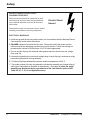
This is the safety alert symbol. It is used to alert you
to potential personal injury hazards. Obey all safety
messages that follow this symbol to avoid possible
injury or death.
DANGER indicates an imminently hazardous situation which, if
not avoided, will result in death or serious injury.
WARNING indicates a potentially hazardous situation which, if
not avoided, could result in death or serious injury.
CAUTION indicates a potentially hazardous situation which, if
not avoided, may result in minor or moderate injury.
CAUTION used without the safety alert symbol indicates a
potentially hazardous situation which, if not avoided, may result
in property damage.
NOTE indicates information about the equipment that you
should pay special attention to.
PNEG-970
S2 Hopper w/ Collector Ring
5
Safety
Safety Instructions
GSI’s principle concern is your safety and the safety of others associated with grain handling equipment.
We want to keep you as a customer. This manual is to help you understand safe operating procedures and
some problems which may be encountered by the operator and other personnel.
As owner and/or operator, it is your responsibility to know what requirements, hazards and precautions
exist, and to inform all personnel associated with the equipment or in the area. Safety precautions may be
required from the personnel. Avoid any alterations to the equipment. Such alterations may produce a very
dangerous situation, where SERIOUS INJURY or DEATH may occur.
This equipment shall be installed in accordance with the current installation codes and applicable regulations which should be carefully followed in all cases. Authorities having jurisdiction should be consulted
before installations are made.
FOLLOW SAFETY INSTRUCTIONS
Carefully read all safety messages in this manual
and on your machine safety signs. Keep signs in
good condition. Replace missing or damaged
safety signs. Be sure new equipment components and repair parts include the current safety
signs. Replacement safety signs are available
from the manufacturer.
Learn how to operate the machine and how to
use controls properly. Do not let anyone operate
without instruction. Keep children and other
unqualified personnel out of the working area at
ALL times
Keep your machinery in proper working condition. Unauthorized modifications to the machine
may impair the function and/or safety and affect
machine life.
Read and Understand Manual.
If you do not understand any part of this manual
and need assistance, contact your dealer.
6
PNEG-970
2 Hopper w/ Collector Ring
Safety
ROTATING FLIGHT
Grain augers can kill or dismember.
DANGER!
Rotating Flight
Keep clear of all augers and never enter the bin unless all
power is disconnected and locked out. Failure to do so will
result in serious injury or death!
OPERATE UNLOAD EQUIPMENT PROPERLY
Make sure ALL equipment is locked in position before operating.
NEVER start equipment until ALL persons are clear of the work area.
Be sure all operators are adequately rested and prepared to
perform all functions of operating this equipment.
NEVER allow any person intoxicated or under the influence of alcohol
or drugs to operate the equipment.
NEVER work alone.
Make sure someone is nearby who is aware of the proper shutdown
sequence in the event of an accident or emergency.
Operate
Unload
Equipment
Safely
ALWAYS think before acting. NEVER act impulsively
around the equipment.
NEVER allow anyone inside a bin, truck, or wagon which is being
unloaded by an auger or conveyor. Flowing grain can trap and
suffocate in seconds.
Use ample overhead lighting after sunset to light the work area.
NEVER drive, stand or walk under the equipment.
ALWAYS lockout ALL power to the equipment when finished
unloading a bin.
PNEG-970
S2 Hopper w/ Collector Ring
7
Safety
INSTALL & OPERATE ELECTRICAL
EQUIPMENT PROPERLY
Electrical controls should be installed by a qualified electrician and must meet the standards set
by the national electrical code and all local and
state codes.
Electric Shock
Hazard
Disconnect and lock out all power sources before
installing wires/cables or servicing equipment.
ELECTRICAL WARNINGS
A. Install and ground the slip ring and the entire unit in accordance with the National Electric
Code and local codes and/or ordinances.
B. DANGER: Hazard of electrical shock or burn. Always disconnect the power from the
collector ring before attempting to perform any service function. Follow lock-out/tag-out
procedures as outlined in OSHA section 1910.147 where appropriate.
C. Do not use this slip ring with electrical loads greater than the rated current and voltage.
(See page 34)
D. Information regarding the current and voltage rating of each slip ring is recorded on a tag
permanently fastened to the ring assembly.
E. 1 R-Series Slip Rings withstand a maximum ambient temperature of 220° F.
F. The model number of the slip ring assembly indicates the ampacity and voltage rating of
each type of ring and brush included on the assembly . (See page 34) Note: the actual
ampacity may be affected by the type and size of the core lead wire (refer to NEC
Table 310-16, 17,18, 19 and applicable notes).
8
PNEG-970
2 Hopper w/ Collector Ring
Safety
PREPARE FOR EMERGENCIES
Be prepared if fire starts.
Keep a first aid kit and fire extinguisher handy.
Keep emergency numbers for doctors, ambulance service, hospital, and fire department near
your telephone.
Keep Emergency Equipment
Quickly Accessible.
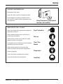
WEAR PROTECTIVE CLOTHING
Wear close fitting clothing and safety equipment
appropriate to the job.
Safety glasses should be worn at all times to
protect eyes from debris.
Eye Protection
Gloves
Wear gloves to protect your hands from sharp
edges on plastic or steel parts.
A respirator may be needed to prevent breathing
potentially toxic fumes and dust.
Steel Toe
Boots
Wear hard hat and steel toe boots to help
protect your head and toes from falling debris.
Remove all jewelry.
Respirator
Tuck in any loose or dangling shoe strings.
Long hair should be tied up and back.
PNEG-970
S2 Hopper w/ Collector Ring
Hard Hat
9
Safety
Decals
A.
The images below show the location of the decals and safety signs which should appear on
the Series II Sweep hopper with collector ring.
Decal “D” (DC-1224) on
top of collector ring
shield plate
Decal “D” (DC-1224) on
side of collector
ring shield
Decal “A”
Location:
Size:
Part No.:
10
Top of shield plate
and side of shield.
2 7/8” x 5”
DC-1224
Please remember safety signs provide important safety information for people
working near bin unloading equipment that is in operation.
Any safety signs that are worn, missing, illegible or painted over should be
replaced immediately. Obtain FREE replacements by contacting GSI.
PNEG-970
2 Hopper w/ Collector Ring
Safety
Decals (cont.)
A.
DANGER Sign No. DC-1395 was supplied with your bin unloading equipment. This safety
sign should be applied to the side of the bin near the bin opening, so it will be viewed by
people entering into the bin storage building. Do not cover any safety signs or any other
signs that are already there.
B.
If the safety sign location suggested is not in full view because of equipment
modifications, other equipment in the area or any reason, then locate the safety sign in a
more suitable location.
C.
Be certain the surface is clean, dry and free of dirt and oil. Peel paper backing from
decals and stick into place. The adhesive backing will bond on contact.
Please remember, safety signs provide important safety information for people
working near bin unloading equipment that is in operation.
ROTATING FLIGHTING!
THIS BIN IS EQUIPPED WITH GRAIN AUGERS
WHICH CAN KILL OR DISMEMBER.
KEEP CLEAR OF ALL AUGERS AND NEVER ENTER
THIS BIN UNLESS ALL POWER IS
DISCONNECTED AND LOCKED OUT.
FAILURE TO DO SO WILL RESULT IN
SERIOUS INJURY OR DEATH!
DC-1395
If the Safety Sign cannot be easily read for any reason or has been painted over,
replace it immediately.
Additional Safety Signs may be obtained free of charge from your dealer, distributor
or ordered from the factory.
Order SAFETY SIGN NO. DC-1395
PNEG-970
S2 Hopper w/ Collector Ring
11
Safety
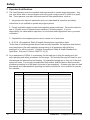
7. Operator Qualifications.
A. The User/Operator must be competent and experienced to operate auger equipment. Anyone who works with or around augers must have good common sense in order to be qualified. These persons must also know and meet all other qualifications, such as:
1. Any person who has not read and/or does not understand all operation and safety
instructions is not qualified to operate any auger systems.
2. Certain regulations apply to personnel operating power machinery. Personnel under the
age of 18 years may not operate power machinery, including augers. It is your
responsibility, as owner and/or supervisor, to know what these regulations are in your area
or situation.
3. Unqualified or incompetent persons are to remain out of work area.
4. O.S.H.A. (Occupational Safety & Health Administration) regulations state:
“At the time of initial assignment and at least annually thereafter, the employer shall instruct
every employee in the safe operation and servicing of all equipment with which the
employee is, or will be involved.” (Federal Occupational Safety & Health Standards for
Agriculture. Sub part D, Section 19287.57 (a) (6).
B. As a requirement of OSHA, it is necessary for the employer to train the employee in the
safe operating and safety procedures for this auger. We included this sign-off sheet for your
convenience and personal record keeping. All unqualified people are to stay out of the work
area at all times. It is strongly recommended that another qualified person who knows the
shutdown procedure is in the area in the event of an emergency. A person who has not read
this manual and understands all operating and safety instructions, is not qualified to operate
the machine.
D a te
E m p l o y e e s N a m e ( p r in t e d )
E m p lo y e e s S ig n a t u r e
1
2
3
4
5
6
7
8
9
10
11
12
13
14
15
16
17
18
19
20
21
22
23
24
25
12
PNEG-970
2 Hopper w/ Collector Ring
Introduction
1. Product Information
A. The Series II Sweep Hopper with Collector Ring includes the following components:
- hopper
- collector ring
- center brace support
- collector ring shield
NEVER enter a grain bin unless ALL power driven equipment has been shutdown. Disconnect and lockout power before entering the bin or servicing the
equipment.
2. General information.
A. GSI reserves the right to improve its product whenever possible and practical to do so. We reserve
the right to change, improve and modify products at any time without obligation to make changes,
improvements and modifications on equipment sold previously.
B. This new hopper with collector ring has been engineered and manufactured to give years of
dependable service. The care and maintenance of this equipment will affect the satisfaction and
service obtained. By following the instructions and suggestions recommended, the owner should
receive quality service for many years. If additional information or assistance should be required,
please contact GSI.
C. It is important to check both the quantity of parts and their descriptions with the packing list enclosed
within each package. All claims for freight damage or shortage must be made by the consignee
within ten (10) days from the date of the occurrence of freight damage. The consignee should
accept the shipment after noting the damage or loss.
3. Capacities and Specifications
Electrical controls and wiring should be installed by a qualified electrician. The
motor disconnect switches and conductor cables should comply with the National Electrical code and any local codes which apply. Reset and motor starting stations should be located so that the operator can see that all personnel
are clear of the equipment.
A. Disconnect and lockout the power before entering the bin.
B. Disconnect and lockout the power before servicing the equipment.
There should ALWAYS be two (2) people in the work area.
main power disconnect switch capable of being locked only in the OFF position
Ashould
be used. It should be locked whenever work is being done on the hopper.
PNEG-970
S2 Hopper w/ Collector Ring
13
Introduction
4. Slip Ring Information
Slip rings must be enclosed and protected from any contact by personnel. Means for the
provision of this protection is the responsibility of the user. Various enclosure styles are
available from Insul-8.
Specifications & Listings
A. R-Series Slip Ring products are built to UL specifications but are not generally certified or
listed by any independent certifying or regulatory body.
B. The following specifications apply to all RSeries Slip Rings:
1. R-Series Slip Rings are intended for industrial use and require a permanent mounting
means.
2. Maximum RPM for units w/o ball bearings is 125. Maximum for units with ball bearings
is 500 RPM.
Temperature & Ampere/Voltage Ratings
A. R-Series Slip Rings withstand a maximum ambient temperature of 220° F.
B. The model number of the slip ring assembly indicates the ampacity and voltage rating of
each type of ring and brush included on the assembly . (See page 34) Note: the actual
ampacity may be affected by the type and size of the core lead wire (refer to NEC
Table 310-16, 17,18, 19 and applicable notes).
Markings
1. Every slip ring is marked with a label on the outboard bearing (or enclosure) which
includes the Insul-8/IER name and logo, the product catalog number and the individual
product serial number.
2. The marking on slip rings includes the maximum amperage and voltage.
14
PNEG-970
S2 Hopper w/ Collector Ring
Assembly
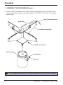
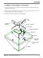
1. ASSEMBLE THE CROSSBRACE
A. Assemble the 1" x 9 3/8" conduit to the 1" chase nipple using one (1) 1" conduit coupling.
B. Feed the nine (9) stranded wires from the collector ring through the conduit assembly and
fasten it to the collector ring.
nine (9) stranded wires
1" chase nipple
1" conduit coupling
1" x 9 3/8" conduit
collector ring
PNEG-970
S2 Hopper w/ Collector Ring
15
Assembly
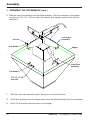
1. ASSEMBLE THE CROSSBRACE (cont.)
C. Feed the nine (9) stranded wires from the collector ring through the pivot tube and bolt the
collector ring to the crossbrace assembly using four (4) 1/4"-20 x 1" hex bolts, lock washers,
and hex nuts.
nine (9) stranded wires
pivot tube
crossbrace assembly
1/4"-20 x 1" hex bolt
collector ring
lock washer
hex nut
16
Do not completely assemble the remaining hopper parts until wiring is complete!
PNEG-970
S2 Hopper w/ Collector Ring
Assembly
1. ASSEMBLE THE CROSSBRACE (cont.)
D. Bolt the collector ring shield to the crossbrace assembly using four (4) 1/4"-20 x 1" hex bolts,
flat washers, lock washers, and hex nuts. Do not use the remaining bolts.
crossbrace assembly
1/4"-20 x 1" hex bolt
flat washer
collector ring shield
lock washer
hex nut
PNEG-970
S2 Hopper w/ Collector Ring
17
Assembly
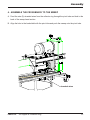
1. ASSEMBLE THE CROSSBRACE (cont.)
E. Slide the lower tube assembly into the shield assembly. Bolt the crossbrace to the hopper
using four (4) 1/2"-13 x 1 3/4" hex bolts, flat washers, lock washers, and hex nuts (One on
each side.).
crossbrace
assembly
hex nut
lock washer
hopper
lower tube
assembly
flat washer
1/2"-13 x 1 3/4"
hex bolt
F.
Slide the lower tube assembly against the hopper and mark the center.
G.
Unbolt the crossbrace from the hopper and remove the shield assembly from the crossbrace.
H.
Drill a 7/8" hole at the marked location on the hopper.
18
PNEG-970
S2 Hopper w/ Collector Ring
Assembly
2. WIRE THE COLLECTOR RING
Electrical controls and wiring should be installed by a qualified electrician.
The motor disconnect switches and conductor cables should comply with
the National Electrical code and any local codes which apply. Reset and
motor starting stations should be located so that the operator can see that
all personnel are clear of the equipment.
Note:The liquid-tight flex conduit may need to be trimmed to length.
A. Attach the 1" liquid-tight flex conduit coupling to one end of the 1" x 16" liquid-tight flex
conduit.
B. Attach the 1" x 45 degree liquid-tight flex conduit coupling to the other end of the 1" x 16"
liquid tight flex conduit.
C. Remove the protective housing from the collector ring.
D. Feed the multi-conductor cord through the conduit assembly and the 1" conduit hub on the
collector ring.
E. Attach the 1" x 45 degree liquid-tight flex conduit coupling to the 1" conduit hub on the
collector ring. Be sure to turn the conduit assembly down .
1" x 45 degree flex
conduit coupling
multi-conductor cord
collector ring hub
1" x 16" flex conduit
1" flex conduit
coupling
PNEG-970
S2 Hopper w/ Collector Ring
19
Assembly
2. WIRE THE COLLECTOR RING (cont.)
F.
Wire the multi-conductor cord to the collector ring using the fork terminals provided in the
following manner.
1. Thermal Protection Leads
a. Wire the "P1" lead from the control panel to ring "1".
b. Wire the "P2" lead from the control panel to ring "2".
2. Drive Motor Leads
a. Wire the three (3) power leads to rings "3", "4", and "5".
b. Wire the ground lead to ring "9".
3. Auger Motor Leads
a. Wire the three (3) power leads to rings "6", "7", and "8".
b. Wire the ground lead to ring "9".
G.
20
Replace the protective housing onto the collector ring.
PNEG-970
S2 Hopper w/ Collector Ring
Assembly
3. ASSEMBLE THE CROSSBRACE TO THE HOPPER
A. Feed the multi-conductor cord through the collector ring shield, lower tube assembly, and
drilled hole in hopper side.
B. Bolt the collector ring shield to the crossbrace assembly using sixteen (16) 1/4"-20 x 1" hex
bolts, flat washers, lock washers, and hex nuts.
C. Slide the lower tube assembly into the shield assembly.
crossbrace
assembly
1/4"-20 x 1" hex bolt
flat washer
collector ring shield
lock washer
hex nut
lower tube
assembly
multi-conductor
cord
hopper
PNEG-970
S2 Hopper w/ Collector Ring
21
Assembly
3. ASSEMBLE THE CROSSBRACE TO THE HOPPER (cont.)
D. Making sure the lower tube assembly and drilled hole are aligned, bolt the crossbrace to the
hopper using eight (8) 1/2"-13 x 1 3/4" hex bolts, flat washers, lock washers, and hex nuts.
crossbrace
assembly
hopper
hex nut
lock washer
1/2"-13 x 1 3/4"
hex bolt
E.
Attach the 1" liquid-tight flex conduit coupling on the conduit assembly to the hopper.
F.
Slide the lower tube weldment against the hopper and tack weld into position.
22
PNEG-970
S2 Hopper w/ Collector Ring
Assembly
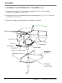
4. ASSEMBLE THE CROSSBRACE TO THE SWEEP
A. Feed the nine (9) stranded wires from the collector ring through the pivot tube and hole in the
back of the sweep head section.
B. Align the hole in the backshield with the pivot tube and push the sweep onto the pivot tube.
stranded wires
PNEG-970
S2 Hopper w/ Collector Ring
23
Assembly
3. ASSEMBLE THE CROSSBRACE TO THE SWEEP (cont.)
C. Connect the pivot plate to the backshield using two (2) 1/2"-13 x 1 3/4" hex bolts,
flat washers, lockwashers, and hex nuts.
D. Fasten the pivot rod to the backshield and pivot plate using two (2) 1/2"-13 x 2" hex bolts,
lockwashers, and hex nuts.
E. Screw the 45 degree grease fitting into the crossbrace assembly.
1/2"-13 x 2" hex bolt
pivot rod
hex nut
pivot tube
lockwasher
flat washer
pivot plate
1/2"-13 x 1 3/4" hex bolt
crossbrace
assembly
45 degree
grease fitting
24
PNEG-970
S2 Hopper w/ Collector Ring
Assembly
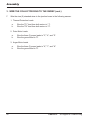
3. WIRE THE COLLECTOR RING TO THE SWEEP
A. Attach one(1) 1" liquid-tight flex conduit coupling to each end of the 1" x 48" liquid-tight flex
conduit.
B. Feed the nine (9) stranded wires from the collector ring through the 1" conduit coupling and
1" x 48" liquid-tight flex conduit assembly.
C. Attach the 1" x 48" liquid-tight flex conduit assembly to the pivot tube using the 1" conduit
coupling.
1" flex conduit
coupling
pivot tube
1" conduit
coupling
1" x 48" flex
conduit
D. Feed the nine (9) stranded wires from the collector ring through one of the holes in the right
junction box.
E. Connect the 1" x 48" liquid-tight flex conduit assembly to the junction box using the 1" liquidtight flex conduit coupling.
PNEG-970
S2 Hopper w/ Collector Ring
25
Assembly
3. WIRE THE COLLECTOR RING TO THE SWEEP (cont.)
F.
Wire the nine (9) stranded wires to the junction boxes in the following manner.
1. Thermal Protection Leads
a.
b.
Wire the "P1" lead from both motors to "1".
Wire the "P2" lead from both motors to "2".
2. Drive Motor Leads
a.
b.
Wire the three (3) power leads to "3", "4", and "5".
Wire the ground lead to "9".
3. Auger Motor Leads
a.
b.
26
Wire the three (3) power leads to "6", "7", and "8".
Wire the ground lead to "9".
PNEG-970
S2 Hopper w/ Collector Ring
Start-Up
1. Preform Pre-Start Checks
Warning! To ensure that the drive is not unexpectedly started, turn off and
lock out or tag out the power source before proceeding. Failure to observe
these precautions could result in bodily injury.
Danger! Failure to perform any or all of these pre-start checks may cause
damage to the equipment and/or cause SERIOUS INJURY or DEATH to those
in the work area.
Failure to perform any or all of these pre-start checks may also be a misuse
of the equipment. Any misuse of the equipment may void the warranty.
A. Make sure ALL shields are in place.
ALWAYS keep ALL guards and shields in place, until all the power is
disconnected and locked out.
B. Inspect the collector ring for any problems or potential problems.
C. Be aware of any emergency shutdown procedures. Two (2) people must always be in a
position where the operation of the equipment can be monitored.
D. Before starting the auger for the first time, make sure that all parts are assembled correctly
according to the instructions in this manual.
Make certain ONLY trained operators are in the work area before operating or
moving the machine. Two (2) people must always be in a position where the
operation of the equipment can be monitored.
PNEG-970 S2 Hopper w/ Collector Ring
27
Maintenance
1. Maintain the Hopper
ALWAYS shutdown and disconnect the power supply before adjusting,
servicing or cleaning the equipment.
A. Use caution when repairing or replacing equipment parts.
B. Make sure ALL decals are legible and tightly attached to the hopper. If necessary, replace
them FREE OF CHARGE by contacting GSI at:
GSI
P.O. Box 20
1004 E. Illinois St.
Assumption, IL 62510
(217) 226-4421
C. Make sure ALL electrical wiring is not damaged, and that it meets proper wiring codes.
D. Make sure ALL components are in good working condition before use.
E. Grease the center pivot tube at least two (2) times each season.
28
PNEG-970
S2 Hopper w/ Collector Ring
Maintenance
2. Collector Ring Maintenance
3. To remove and replace the brush:
a) remove the clamp screw from the brush
holder
A. Lubrication
1. All bearings are lubricated for life at the factory.
Additional lubrication should not be required.
2. CAUTION: Do not apply any lubricants or
solvent cleaning agents to any part of the slip
ring.
b) remove the screw from the brush lead
c) remove the brush holder
d) replace the brush
e) reassemble.
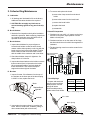
B. Brush Holders
E. Brush Fit Inspection
1. Make the first inspection shortly after installation
and before operation. Make continuing inspections
on a regular basis after every 200-400 hours of
operation under normal conditions.
C. Brush Holders
1. Inspect brush holders for proper alignment.
Locate brush holders so that the entire brush
contact surface rides squarely on the ring with the
brush moving freely in the brush holder. Position
brush holders so that the brush makes contact
with the middle of the conductor and is not offset.
1. Brushes must run at 90° ± 3° square on the rings.
If brush is not square, adjust position of brush
holder on brush post.
2. Brushes need not run on the center of the rings,
but there should be no forceful friction against the
insulators.
3. The brush spring cross-bar must be seated in the
brush slot.
Cross-bar Seated
in Brush Slot
Brush Holder
2. Check brush holder clamps for tightness. Set
clamp bolts at 10 in-lb max.
3. Inspect brush terminations at the holder to assure
that no external force is imposed on the holder.
We recommend flexible or soft wire leads for
these terminations. Use external clamps to
support the entire weight of the leads.
D. Brushes
Brush
Insulator
1. Inspect for wear. If the distance from the top of
the insulator to the lower part of the brush spring
is 0.093" or less, replace the brush.
Brush
Replace Brush
@ 0.093"
Insulator
Ring Surface
Brush
Springs
F. 3.2.4
Brush
Springs
1. 3.2.4.1
Inspect and
test brush
Inspect
and test
to assure
brush tosprings
springs
assure uniform
uniform
brush Ifpressure.
If
brush
pressure.
brush
brush fall
springs
springs
below fall below
recommended
pressure,
recommended
pressure,
replace entire brush holder .
replace entire brush holder .
Brush
Amperage
Spring
Pressure
15
1.0 lb. min
35
1.5 lbs. min
75
3.0 lbs. min
Table 3.3.3 Brush Spring Tension
5 lb. Scale
Brush Spring
2. Inspect brush contact surface by removing the
brush. Remove surface dirt, oxidation, pitting, or
other contaminants (with a wire brush).
PNEG-970
S2 Hopper w/ Collector Ring
29
Maintenance
2. Collector Ring Maintenance (Cont.)
G. Rings
1. Inspect the ring surface for dirt, oxidation, or
other contaminants. A properly operating ring will
have a film that appears burnished in color with a
darker surrounding color where the brushes
track. If the ring requires cleaning, order Slip
Ring Polishing Kit #41286.
H. Electrical Connections
1. Inspect all electrical connections for corrosion
and tightness. Clean corroded parts with a wire
brush and/or muriatic acid. Loose and/or
corroded terminations will cause a concentration
of excessive heat.
I. Brush Rigging
1. Brush posts are supported between two outboard
bearings. The brush posts extend to the outboard
bearings and are secured by a notch in the
outboard
2. Spacing between the outboard bearings is critical
to assure the free rotation of the brush rigging.
The brush posts are cut to an exact length in
order to provide the proper spacing. Locate the
outboard bearings against the insulator and have
a 0.20" clearance without deformation of the
material. CAUTION: Do not over-tighten the
outboard brush post jam nuts. Make a final check
to assure there is no binding of the outboard
brush rigging or binding of brushes with insulator
barriers.
3. Periodically perform an inspection by removing the
enclosure and checking for condensation, water
and dust collection. If contaminants are found,
wipe the enclosure and the assembly with a lint
free cloth. If the problem persists, take steps to
remedy the leakage or condensation problem.
K. Slip Ring Storage
1. When storing the slip ring, keep it at room
temperature in a clean, dry, protective place.
Place self-contained or bagged absorbent material
in the collector ring enclosure during extended
periods of storage. Remove absorbent material
before putting collector ring into operation.
L. Serial Number
1. Make the following information available when
ordering replacement parts or discussing the slip
ring with the factory by recording the information in
the spaces provided here. This information is
located on your packing slip, factory invoice, and
serial number tag.
Catalog No. Slip Ring:_________________________
Serial No.:__________________________________
J. Enclosure Inspection
1. Moisture is a major cause of slip ring
deterioration. Water will corrode parts and
breakdown insulation. Dust and dirt present
within the enclosure will effect the proper
operation of the assembly. Most dusts cause
excessive brush and slip ring wear, and
conductive dust, if allowed to accumulate, will
form a path for short circuiting.
Date of Purchase:____________________________
2. A properly designed NEMA 4 enclosure will be
dust tight and watertight. However, NEMA 4
enclosures do not eliminate internal
condensation. Condensation can be eliminated
with the addition of a breather , drain, and a
thermostatically controlled heater.
30
PNEG-970
S2 Hopper w/ Collector Ring
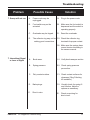
Troubleshooting
Problem
1. Sweep will not run.
Possible Cause
Solution
A.
Power cords may be
unplugged.
A1. Plug in the power cords.
B.
Foot switch may not be
actuated.
B1. Make sure the foot switch is
depressed and the switch is
operating properly.
C.
Overloads may be tripped.
C1. Reset the overloads.
D.
The collector ring may not be D1. Check the collector ring
making good connections.
terminals for proper contact.
D2. Make sure the springs have
correct tension according to
the owners manual.
1. Intermittent Signal
or Loss of Signal
PNEG-970
A.
Brush wear.
A1. Verify brush wear per section.
B.
Spring pressure.
B1. Check spring pressure
per section.
C.
Dirty contact surface.
C1. Check contact surfaces for
cleanness (Ring Polishing
Kit available.)
D.
Bad springs.
D1. Visually check for spring fit
and function. Adjust or
replace as necessary.
E.
Short in wire.
E1. Check core wiring for
short circuit.
S2 Hopper w/ Collector Ring
31
Parts
12" HOPPER COMPONENTS
13
5
14
10
5
15
12
10
11
9
8
7
6
4
5
3
2
1
32
PNEG-970
S2 Hopper w/ Collector Ring
Parts
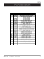
12" & 16" HOPPER COMPONENTS
Ref. #
1
Part #
GC04615
GC11328
2
3
4
5
6
7
8
9
10
11
12
13
14
15
N/S
N/S
N/S
N/S
N/S
N/S
N/S
N/S
N/S
N/S
N/S
PNEG-970
GC04624
GC11326
GC07602
GC07876
S-8518
GC07881
GC04654
GC04547
GC04653
S-8519
S-2122
GC07880
GC07877
GC07575
GC06716
GC06717
S-8427
S-1102
S-1430
S-2041
S-236
S-3208
S-3883
S-4110
S-4329
S-6998
S-7509
S-7510
Description
S2 Sweep Collector Ring Hopper
Standard Capacity 16" Square Discharge
High Capacity 36" Square Discharge
Lower Tube Assembly
16" Square Discharge
36" Square Discharge
Power Cord 10Ga/9 Conductor x 12'
S2 Sweep Collector Ring Shield
Conduit Ftg 1" Straight Rigid-Flex
Conduit, 1" Flex x 16"
Conduit Ftg 1" 45Degree Rigid-Flex
Collector Ring, Insul 8 Model - 9 Ring
Conduit, 1" x 9 3/8" Long
Conduit, Coupling 1" Galv.
Conduit, 1" Steel Chase Nipple
S2 Sweep Collector Ring Hopper Crossbrace-12"
S2 Sweep Collector Ring Hopper Crossbrace-16"
Conduit, 1" Flex x 48"
S2 Sweep Pivot Rod Assembly-12"
S2 Sweep Pivot Rod Assembly-16"
Grease Ftg 45Degree 1/4"-28 UNF
Nut Hex 1/4"-20 Zn Gr2
Washer Flat 1/4" SAE Zn Gr2
Washer Lock Split 1/4" Med Zn
Washer Lock Split 1/2" Med Zn
Washer Lock Split 5/8" Med Zn
Bolt HHCS 1/2"-13 x 1 3/4" Zn Gr8
Nut Hex 5/8"-11 Zn Gr5
Bolt HHCS 5/8"-11 x 2" Zn Gr8
Bolt HHCS 1/4"-20 x 1" Zn Gr5
Washer Flat 1/2" USS
Nut Hex 1/2"-13 Zn Gr2
S2 Hopper w/ Collector Ring
33
Parts
Collector Ring Replacement Parts
7.1 Parts Descriptions
(Blank) = No Enclosure
R = Revolving Unit (RU)
Required
Optional
S = Swivel Unit (SU)
(Blank) = No Special Configuration
X = Explosion-Proof Enclosure
W = Explosion Proof Enclosure
w/ 1" Air Passage
T = Ball Bearings on Brush Carriage
(standard is brass sleeve bearing)
N = Non-Self- Contained
(Kit Ring, no enclosure)
U = Wrap Around Cover
(BLANK) = Single Brush
(Ring Profile Section) D - = All Circuits Double Brushed
(Amperage Profile Section) D = This Amperage Double Brushed
Number of Conductors
R A X R D
SPEC *
D A 03
Amperage Profile Section
Multiple Sections Possible
Ring Profile Section
Slip Ring Bore Size
2
Z
A
B, C, D
E, F, G, H
J, K
Special
Bore
1.50
30067A
30066A
30068A
30068A
30069A
02840
02841
02842
02843
N/A
N/A
N/A
2.5, 3.0, 3.5
30067B
30066B
30068B
30068B
30069B
02845
02846
02847
02848
4.0, 4.5, 5.0, 6.0
30067C
30066C
30068C
30068C
30069C
02850
02851
02852
02853
8.0, 10.0
30067D
30066D
30068D
30068D
30069D
02855
02856
02857
02858
DRA3-20A-2500
DRA3-20A-4000
DRA3-20A-8000
03309
03248
03247
03248
03247
03248
Brushes
*
*
1
Brush
Holders
A=
B=
C=
D=
E=
F=
G=
H=
J=
K=
L=
M=
10 AMP / 250 V
15 AMP / 250 V
35 AMP / 250 V
35 AMP / 600 V
75 AMP / 600 V
110 AMP / 600 V
150 AMP / 600 V
225 AMP / 600 V
300 AMP / 600 V
200 AMP / 600 V
400 AMP / 600 V
600 AMP / 600 V
Consult the Factory for Custom Application Configurations
Single
Double
02807
02800
28000
02807
02801
02808
02801
02808
02802
02809
02803
02810
02804
02811
02805
02805 (x2)
02806
02806 (x2)
Brushes & Holders
Sold as a Unit in this
AMP / VOLT Range
1
2
Two 35 Amp Brushes
Replace One 75 Amp Brush
34
PNEG-970
S2 Hopper w/ Collector Ring
WARRANTY
THE GSI GROUP, INC. ("GSI") WARRANTS ALL PRODUCTS MANUFACTURED BY GSI
TO BE FREE OF DEFECTS IN MATERIAL AND WORKMANSHIP UNDER NORMAL USAGE AND CONDITIONS FOR A PERIOD OF 12 MONTHS AFTER RETAIL SALE TO THE
ORIGINAL END USER OF SUCH PRODUCTS. GSI'S ONLY OBLIGATION IS, AND
PURCHASER'S SOLE REMEDY SHALL BE FOR GSI, TO REPAIR OR REPLACE, AT
GSI'S OPTION AND EXPENSE, PRODUCTS THAT, IN GSI'S SOLE JUDGMENT, CONTAIN A MATERIAL DEFECT DUE TO MATERIALS OR WORKMANSHIP. ALL DELIVERY
AND SHIPMENT CHARGES TO AND FROM GSI'S FACTORY WILL BE PURCHASER'S
RESPONSIBILITY. EXPENSES INCURRED BY OR ON BEHALF OF THE PURCHASER
WITHOUT PRIOR WRITTEN AUTHORIZATION FROM AN AUTHORIZED EMPLOYEE
OF GSI SHALL BE THE SOLE RESPONSIBILITY OF THE PURCHASER.
EXCEPT FOR THE ABOVE STATED EXPRESS LIMITED WARRANTIES, GSI MAKES NO WARRANTY OF ANY KIND, EXPRESSED OR IMPLIED, INCLUDING, WITHOUT LIMITATION, WARRANTIES OF MERCHANTABILITY OR FITNESS FOR A PARTICULAR PURPOSE OR USE IN
CONNECTION WITH (i) PRODUCT MANUFACTURED OR SOLD BY GSI OR (ii) ANY ADVICE,
INSTRUCTION, RECOMMENDATION OR SUGGESTION PROVIDED BY AN AGENT, REPRESENTATIVE OR EMPLOYEE OF GSI REGARDING OR RELATED TO THE CONFIGURATION,
INSTALLATION, LAYOUT, SUITABILITY FOR A PARTICULAR PURPOSE, OR DESIGN OF SUCH
PRODUCT OR PRODUCTS.
IN NO EVENT SHALL GSI BE LIABLE FOR ANY DIRECT, INDIRECT, INCIDENTAL OR CONSEQUENTIAL DAMAGES, INCLUDING, WITHOUT LIMITATION, LOSS OF ANTICIPATED PROFITS OR BENEFITS. PURCHASER'S SOLE AND EXCLUSIVE REMEDY SHALL BE LIMITED TO
THAT STATED ABOVE, WHICH SHALL NOT EXCEED THE AMOUNT PAID FOR THE PRODUCT PURCHASED. THIS WARRANTY IS NOT TRANSFERABLE AND APPLIES ONLY TO THE
ORIGINAL PURCHASER. GSI SHALL HAVE NO OBLIGATION OR RESPONSIBILITY FOR ANY
REPRESENTATIVE OR WARRANTIES MADE BY OR ON BEHALF OF ANY DEALER, AGENT
OR DISTRIBUTOR OF GSI.
GSI ASSUMES NO RESPONSIBILITY FOR FIELD MODIFICATIONS OR ERECTION DEFECTS
WHICH CREATE STRUCTURAL OR STORAGE QUALITY PROBLEMS. MODIFICATIONS TO
THE PRODUCT NOT SPECIFICALLY COVERED BY THE CONTENTS OF THIS MANUAL WILL
NULLIFY ANY PRODUCT WARRANTY THAT MIGHT HAVE BEEN OTHERWISE AVAILABLE.
THE FOREGOING WARRANTY SHALL NOT COVER PRODUCTS OR PARTS WHICH HAVE
BEEN DAMAGED BY NEGLIGENT USE, MISUSE, ALTERATION OR ACCIDENT. THIS WARRANTY COVERS ONLY PRODUCTS MANUFACTURED BY GSI. THIS WARRANTY IS EXCLUSIVE AND IN LIEU OF ALL OTHER WARRANTIES EXPRESS OR IMPLIED. GSI RESERVES
THE RIGHT TO MAKE DESIGN OR SPECIFICATION CHANGES AT ANY TIME.
PRIOR TO INSTALLATION, PURCHASER HAS THE RESPONSIBILITY TO RESEARCH AND
COMPLY WITH ALL FEDERAL, STATE AND LOCAL CODES WHICH MAY APPLY TO THE
LOCATION AND INSTALLATION.
THIS EQUIPMENT SHALL BE INSTALLED IN
ACCORDANCE WITH THE CURRENT INSTALLATION
CODES AND APPLICABLE REGULATIONS WHICH
SHOULD BE CAREFULLY FOLLOWED IN ALL CASES.
AUTHORITIES HAVING JURISDICTION SHOULD BE
CONSULTED BEFORE INSTALLATIONS ARE MADE.
P.O. Box 20
1004 E. IL. St
Assumption IL. 62510
(217) 226-4421
(217) 226-4429
Copyright © 2005 by The GSI Group
Printed in the USA