1
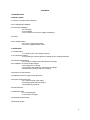
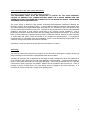
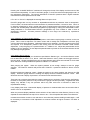
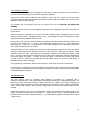
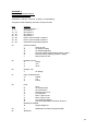
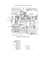
B.4 Pirani connectors.
Two of these are supplied with the instrument in the accessory pack. They are 5 way DIN audio free
plugs with screen. Types with or without latches may be used.
Pin connections are:
1
Bridge supply 0v
2
Signal voltage
3
Bridge supply 2.06v
red
green
yellow
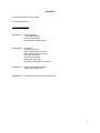
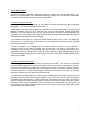
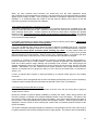
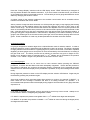
B.5 Remote connector.
This is a 9 way "D" type female connector. Used pin connections and signal names are:
2
5
Transmitted data
Signal ground
The signal levels on pin 2 are compatible with those of the RS232C standard.
The maximum length of cable which can be accommodated depends on the siting and construction of
the cables. Cables of over a few metres length should be screened and the screen should be
connected to ground at the computer end.
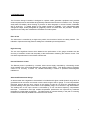
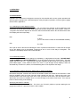
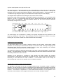
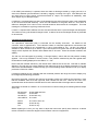
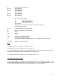
B.6 Auxiliary connector.
External connections should be made to a free 8 pin DIN audio connector with screen, as supplied in the
accessory kit. Types with or without latches may be used.
Connections for the recorder output are:
1
Signal voltage
6
Signal return (earth)
Connections to the capacitance manometer are:
2
+15 volt supply
3
Signal voltage (i.e. manometer output)
4
Signal return and supply 0 volts
5
-15 volt supply
Connections to the remote inhibit lines are:
7
Not Inhibit
8
Signal return (logic ground )
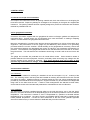
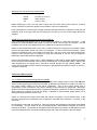
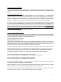
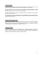
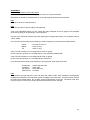
B.7 Thermocouple gauge connectors.
Two of these are supplied with the instrument in the accessory pack. They are 5 way DIN audio free
plugs with screen. Types with or without latches may be used.
Their connections are:
4
1
2
5
Heater +
Heater Thermocouple +
Thermocouple -
Pin 3 should not be connected.
21